

Page 1
Engineering Specification
DEK Part No. 156935
http://www.dek.com
Page 2

Page 3
Copyright (c) 2000 DEK Printing Machines Limited. All Rights Reserved.
Microsoft and MS-DOS are registered trademarks of Microsoft Inc.
Windows and Windows NT are trademarks of Microsoft Inc.
All other brand and product names are trademarks or registered trademarks of their respective holders.
Trademark Acknowledgment
AutoFlex, Form-Flex, Vortex and ProFlow are registered trademarks of DEK Printing Machines Limited.
Copyright Statement
Page 4

Page 5

HORIZON ENGINEERING SPECIFICATION
ENGINEERING SPECIFICATION
GENERAL DESCRIPTION .........1
TECHNICAL SPECIFICATION ........2
MACHINE FOOTPRINT..........5
KEY FEATURES ...........6
Camera System ..........6
Windows NT ..........13
Diagnostics ..........14
SCREEN IMAGE POSITIONING ........16
MACHINE OPTIONS ..........17
ProFlow ...........17
2D Inspection ..........19
Under Screen Cleaner .........24
Paste Dispenser ..........26
Board Clamp Options .........27
Tooling ...........30
Networking ..........36
Generic Equipment Model ........36
Special Board Handling Options .......36
Speed Up ...........37
Remote Board Stop .........37
Statistical Process Control ........38
Remote Product Changeover ........38
Long Board ..........38
Off Line Editor ..........39
Remote Event Monitor.........39
Temperature Control Unit ........39
Environmental Control Unit ........40
Chapter Issue 1 May 00 Engineering Specification
CONTENTS
Page 6

Engineering Specification Chapter Issue 1 May 00
CONTENTS
Page 7

ENGINEERING SPECIFICATION
GENERAL DESCRIPTION
Using a world wide installed base of thousands of 265 printers, DEK has
engineered the evolution of the industry’s most successful screen printer
platform to create the Horizon – a printing machine focused on improving
flexibility, yield and price/performance.
The Horizon adds more features and greater choice, blending proven technology
options and utilization-based process innovation to deliver unique
manufacturing advantages. It is an engineered evolution precisely optimized for
functionality, flexibility, cost-effectiveness and longevity.
Common features evolved from DEK’s 265 family provide immediate user
confidence. In turn, a minimal learning curve and easy transfer of existing
product files result in faster process improvements. Horizon’s intuitive
Windows NT operating system, is the globally accepted user interface to
achieve better productivity effectively.
Horizon’s precision-engineered mechanical assemblies, advanced electronic
control systems and ISO9001 manufacturing procedures combine to deliver
maximum efficiency and quality through high yields, product flexibility and fast
changeover. The Horizon conforms to the following standards:
• CE: 89/392/EEC, 89/336/EEC and 73/23/EEC
• UL 1950, 3rd Edition 1995
• CAN/CSA C22.2 No950-95
Advanced equipment utilization programs to fine tune the process, together with
DEK’s applications resource, extend the reliability production engineers and
line operators can expect from the Horizon. The Horizon package addresses
future capacity requirements through its range of expansion options, process
enhancements and documented upgrade paths.
Chapter Issue 1 May 00 Engineering Specification 1
ENGINEERING SPECIFICATION
GENERAL DESCRIPTION
Page 8
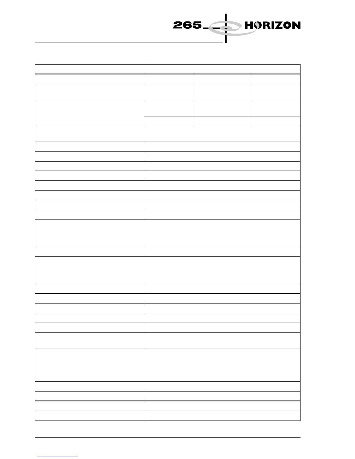
TECHNICAL SPECIFICATION
Screen Frames Specification
Type External (w x l x t) Internal (w x l)
Standard DEK 265 736 x 736 x 38/40mm
(29″ x29″)
660 x 660mm
(26″ x26″)
Optional Chase Adaptors DEK 260 585 x 585 x 38mm
(23″ x23″)
508 x 508mm
(20″ x20″)
Sanyo 550 x 650 x 38mm
Optional Screen Adaptors All common stencil sizes available:
Sanyo, Ekra, Fuji, Panasonic, MPM etc.
Image Position Centre, Front, Custom
Board Handling Specification
Minimum Size 40 x 50mm
Maximum Size 510 x 508mm (620 x 508mm)*
Thickness 0.2 - 6mm
Warpage Up to 8mm including PCB thickness
Underside Component Clearance Programmable 3 - 42mm
Transport Conveyors Programmable motorized
Transport Direction Left to Right
Right to Left
Left to Left
Right to Right
Interface Protocols All popular interfaces available
Board Location Patented Over the Top Clamps
Edge clamping*
Vacuum*
Foil-less Clamps with vacuum*
Registration Fully Automatic Vision
Process Parameters Specification
Print Speed 2 - 150mm/sec
Print Pressure 0 -20kg Programmable (Closed Loop Feedback)*
Print Gap 0 - 6mm
Stencil Seperation Speed: 0.1 - 20mm/sec
Distance:0-3mm
Print Modes ProFlow
Print Print
Print Flood
Flood Print
Adhesive
Paste Knead Programmable: Number, Period, On Demand
Vision Specification
Vision System Cognex 8100 Vision System
Camera Lighting Software Controlled Programmable Lighting
2 Engineering Specification Chapter Issue 1 May 00
ENGINEERING SPECIFICATION
TECHNICAL SPECIFICATION
Page 9
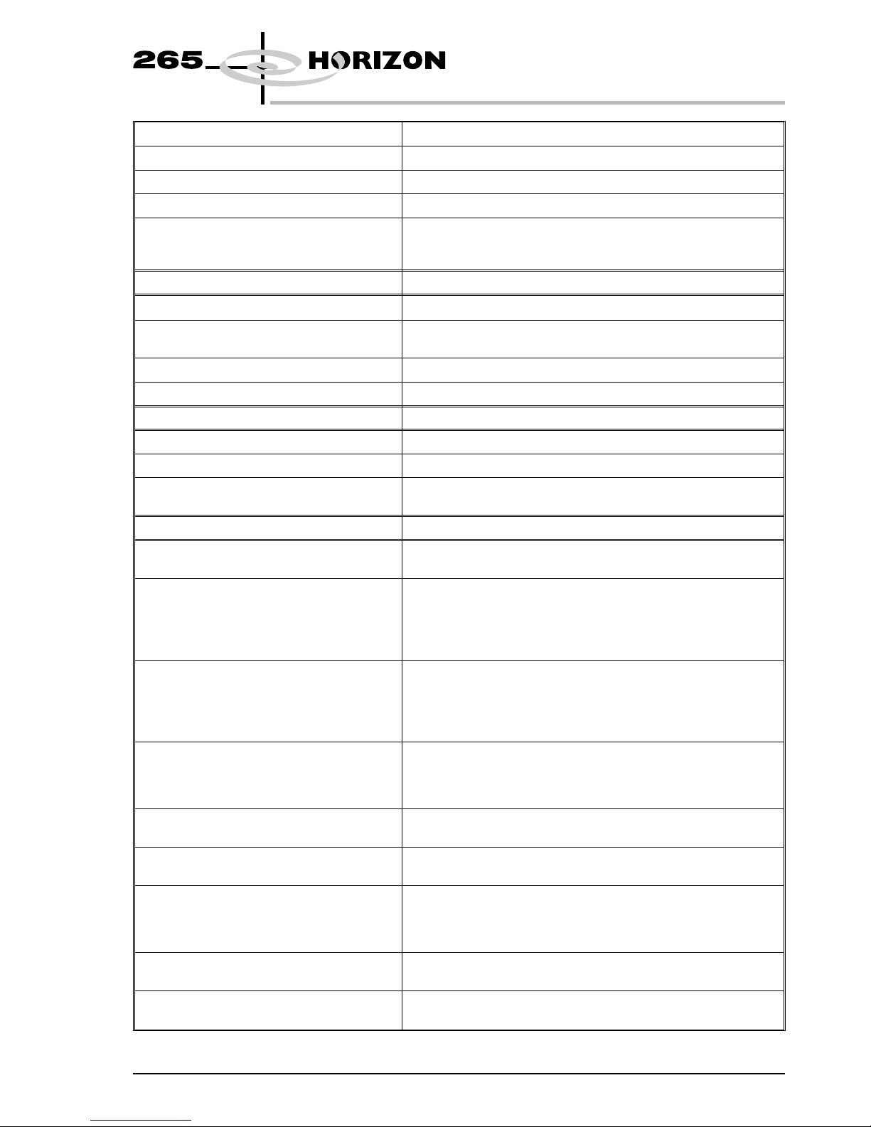
Fiducials 2 or 3
Fiducials Types Synthetic fiducial library or unique pattern recognition
Fiducial Size 0.5 - 3mm
Fiducial Position Anywhere on PCB (see Fiducials, Key Features)
Fiducial Error Recovery Auto Lighting Adjustment
Auto Fiducial Search
Smart Fiducial
Performance Specification
Alignment
Stencil to Board Repeatability 6 sigma @ 25µm
Cycle Time 12.5 secs
10.0 secs*
Product Changeover 2 minutes#
New Product Set Up <10 minutes
Operator Interface Specification
Hardware Colour VGA Touch Screen Display, keyboard and mouse
Software Operating System Windows NT
Manuals Electronically on CD-ROM
Hard Copies Available*
Options Specifications
ProFlow Fully enclosed, high speed DirEKt Imaging system
Optional Temperature Control Unit
2D Inspection Full inspection capability of screen and board:
Basic
Advanced
Automatically triggered recovery sequences
Inspection outputs available to Statistical Process Control software
Tooling Magnetic Pillars
Form-Flex
AutoFlex programmable tooling (35mm pitch)
MultiFlex with or without vacuum
Dedicated Vacuum Plates
Under Screen Cleaner Paper - Fully programmable wet, dry and vacuum assisted paper
under screen cleaner
Vortex - Fully programmable wet/dry and vacuum assisted foam
cassette under screen cleaner
Paste Dispenser Fully programmable automatic paste dispensing system. Available
for 1kg and 500g cartridges
Temperature and Humidity Sensor Sensor to measure and display temperature and humidity with in the
printing area. SPC output available
Environmental Control Temperature Control Unit (TCU):
Controls the temperature of the printing area
Temperature and Humidity Control Unit (ECU):
Controls the temperature and humidity of the printing area
Statistical Process Control On board package to collect, manage and display critical process
parameters
Board Clamps Alternatives Edge Clamps
Foil-less Clamps
Chapter Issue 1 May 00 Engineering Specification 3
ENGINEERING SPECIFICATION
TECHNICAL SPECIFICATION
Page 10

Remote Event Monitoring Desktop application for remote status monitoring and reliability
anaysis of printer
Generic Equipment Model On board package for communications with host using TCP/IP
interface
Selective Print Pass This option enables selective print or pass through of boards
Flexible Board Printing Option enables printing of thin flexible boards
Remote Board Stop Optional alternative to camera board stop for use with large and/or
heavy boards or carriers
Speed Up Option to reduce machine cycle time from 12.5sec to 10sec.
Remote Product Changeover Stand alone database program controlling and monitoring the
product file loaded, matches current board input
Off Line Editor Off line software package to generate and edit product files.
Available on board or via network
Network LAN package to transfer data within the factory network. Package
includes DEK netfile software, which can target product and SPC
files to location on the network
Certification Specification
CE 89/392/EEC
89/336/EEC
73/23/EEC
Subsequent Amendments
ETL UL 1950, 3rd Edition 1995
CAN/CSA C22.2 No 950-95
Services Specification
Power Supply 100, 110, 120, 200, 210, 210, 220, 230, 240 volt Single Phase
50/60Hz
Current:
110V - 16 Amps
120V - 15 Amps
200 - 220V - 8 Amps
230 - 240V - 7 Amps
Air Supply Air to ISO 8573.1 standard quality class 2.3.3
Pressure 5 -8 bar at 5 Litres/min
Shipping Information Specification
Approx Weight 900kg
Approx Dimensions 1314 x 1325 x 1592mm
(51.7″ x 52.1″ x 62.6″)
* Options
# Timed using AutoFlex
4 Engineering Specification Chapter Issue 1 May 00
ENGINEERING SPECIFICATION
TECHNICAL SPECIFICATION
Page 11
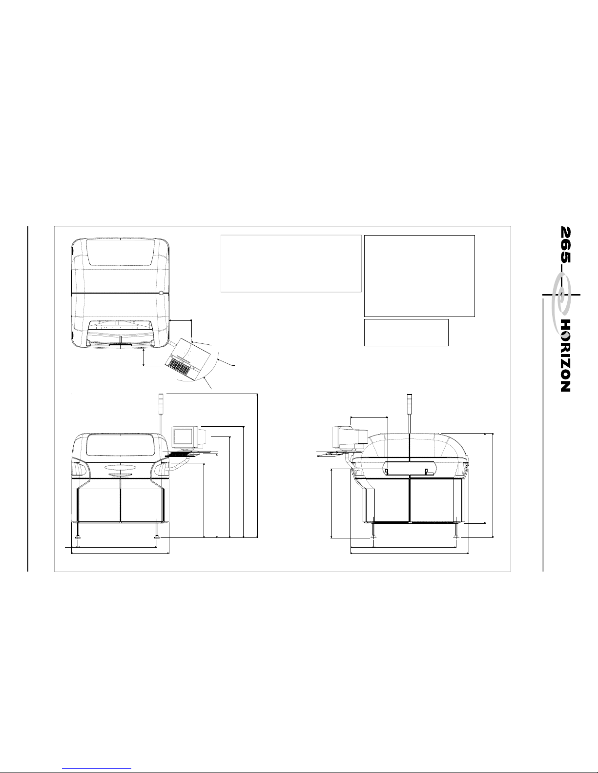
MACHINE FOOTPRINT
Chapter Issue 1 May 00 Engineering Specification 5
ENGINEERING SPECIFICATION
MACHINE FOOTPRINT
1314
85
1064
1113
312
1592
1285
1065
119 5
1435
1572
1490
980 max
243
302
2230
500
R413
Monitor Omitted
for Clarity
Arc of Monitor Arm
Extremity of Monitor Tray
Follows the Arc of Monitor Arm
Plan View
Front View
Side View (Right)
CAUTION
OVER CURRENT PROTECTION. Magnetic/thermal
over current protectors protect the machines’internal
wiring and components from overheating/fire during
fault conditions. DEK require additional machine
supply protection with the fitment of a wall mounted
circuit breaker rated to 16 Amps and conforming to
national/federal regulations.
NOTE
All dimensions in millimetres
Board TransferHeight 820 - 980 mm
Screen Load Height 905 - 1065 mm
Services Required
Voltage:
100/110/120/200/210/220/230/240V Single Phase
50/60Hz
Current:
110V - 16 Amps
120V - 15 Amps
200 - 220V - 8 Amps
230-240V-7Amps
Air Supply:
Air to ISO 8573.1 standard quality class 2.3.3
Pressure 5 - 8 Bar at 5 Litre/min
Weight 900 Kg
Page 12
KEY FEATURES
Camera System The camera assembly integrated into the Horizon is a compact assembly of
optics, lighting and a standard CCIR camera. The camera is fitted with a split
optic unit to allow the camera to capture the image from the stencil and board at
the same time. Thereby, eliminating the relative movement between the images
captured. The camera assembly incorporates ‘Telecentric Lenses’ and ‘Flat
Lighting’.
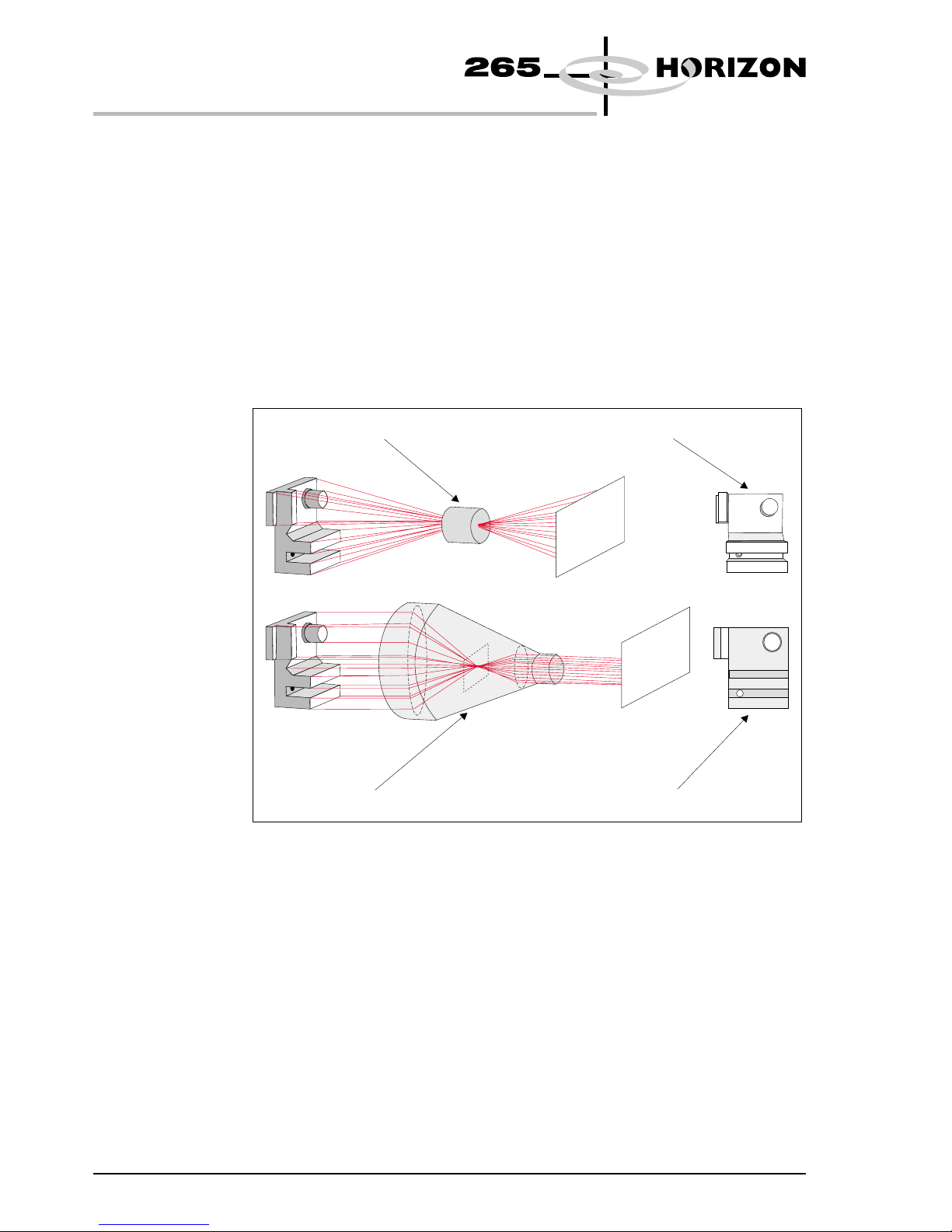
Telecentric Lens The optic unit within the camera assembly uses telecentricity to ensure that
board warping, distance between camera and board and the actual position of the
fiducials within the field of view do not affect the alignment accuracy.
6 Engineering Specification Chapter Issue 1 May 00
ENGINEERING SPECIFICATION
KEY FEATURES
Conventional Lens
Distorted Image
Undistorted Image
Telecentric Lenses Array
Page 13

Variations in the distance between the optic unit and the board fiducials due to
uneven board surface are transparent when using telecentric lenses. With a
standard lens the diameter, centroid and position of a fiducial varies with this
distance, hence key elements in determining alignment of the board vary
depending on where the fiducials lie in the field of view.
Without DEK’s use of telecentric lenses, a pre-alignment stage would have to be
added to bring the fiducials into the centre of the field of view, before carrying
out a final alignment stage.
Chapter Issue 1 May 00 Engineering Specification 7
ENGINEERING SPECIFICATION
KEY FEATURES
Conventional Lens
If the board to camera distance varies due
to uneven board surface, the position and size
of the fiducial will vary accordingly.
Telecentric Lenses Array
Lens
Telecentric Stop
All fiducials seen as
identical wherever they
appear in the field of view.
Page 14
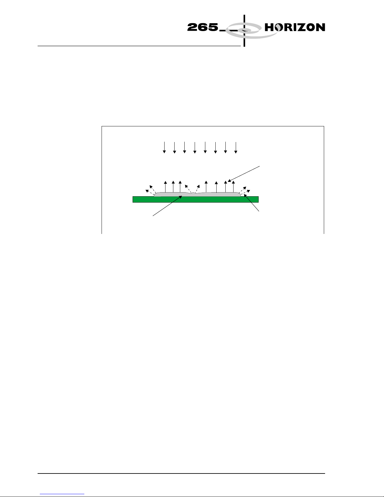
Flat Lighting Essential for any vision system is to have the highest quality images with which
to process. Poor quality images may result in a degradation of image processing
leading to less accurate alignment and if inspection is used, misleading results.
DEK’s camera assembly fitted to the Horizon has been specifically designed to
enable low quality boards to be aligned and inspected with equal accuracy as
gold/copper boards. The lower quality boards have uneven Hot Air Solder
Levelled (HASL) pads and features.
The uneven surface texture and irregularities of these features and pads would
cause dead zones, ie areas where there is no light and hot spots of light caused by
reflection of light from solder pads and wet solder paste.
For high accuracy and reliable image processing DEK has incorporated a flat
lighting design within the camera assembly. This is achieved by utilizing two
light sources:
•
Direct lighting - producing normal incidence and angles up to 25°
•
Indirect/Oblique lighting - producing angles from 25° - 50°
8 Engineering Specification Chapter Issue 1 May 00
ENGINEERING SPECIFICATION
KEY FEATURES
Light from a normal light source
HASL feature
Surfaces not seen
by camera
Surfaces seen
by camera
Page 15

Direct lighting is achieved by a block of six LEDs shining through a diffuser to
produce a very uniform light source. The light is passed through a cube beam
splitter which increases the illumination and the range of angles reaching the
board.
Indirect /Oblique lighting is used in addition to direct lighting to produce light
paths between 25° and 50° to create uniform illumination, eliminating hot spots
of light.
An array of 12 LEDs sited in a polished ring around the lens aperture produce a
light source which is reflected and scattered by the polished surface and the
white paint of the assembly to the fine ground conical inner ring. This produces
very uniform illumination which is radiated in all directions providing a very
balanced illumination of the board.
Chapter Issue 1 May 00 Engineering Specification 9
ENGINEERING SPECIFICATION
KEY FEATURES
Board
LED Array
Inner Ring
Light paths
between 25 and 50
Board
LED Array Diffuser
50/50 Beam Splitter
Light paths
between 0 and 25
Page 16

PatMax The Horizon machine uses PatMax® object location software to produce
accurate repeatable stencil to board alignment. PatMax interprets geometric
shapes within objects. A square fiducial is interpreted by PatMax as four
separate line segments. The advantages of the system are greater accuracy at
lower image quality. The object can be a different size, or different orientation to
the object learned. The target can be partly obscured and degraded.
10 Engineering Specification Chapter Issue 1 May 00
ENGINEERING SPECIFICATION
KEY FEATURES
= Learned fiducial
Non PatMax Object Location Software - Confused Objects
PatMax Object Location Software - Confused Objects
Targ et
Targ et
Interpretation
Interpretation
Result
Result
Fail to Locate
X
Successful Location
of Three Objects
Non PatMax Object Location Software
PatMax Object Location Software
Degraded Object Partial Object
Result
Fiducial Not Found
Result
Successful Location
of Fiducial
Result
Successful Location
of Fiducial
Result
Fiducial Not Found
Page 17

Fiducials The Horizon uses the vision system to capture and process alignment marks or
fiducials to align the stencil to each board before it is printed. The alignment
marks or fiducials are produced as part of the artwork of the board and stencil, in
the same relative position. The information processed is used to correct stencil
to board alignment.
The Horizon has a library of synthetic fiducials of the most commonly found
shapes. The dimensions of these fiducials can be tailored by the operator to fit
the fiducials on the board and stencil. The fiducial on the stencil can be can be
different from the fiducial on the board. After the vision system has been taught
these fiducial parameters, it is able to search the field of view of the camera and
recognize any features which resemble fiducials.
After finding a shape it is assigned a score comparing its shape and size to the
shape and size of the fiducial in the vision system library. This score is set
between 1 and 999, the better the fit the higher the score.
The fiducial shapes available is shown below:
Chapter Issue 1 May 00 Engineering Specification 11
ENGINEERING SPECIFICATION
KEY FEATURES
CIRCLE CROSS DIAMOND TRIANGLE RECTANGLE DOUBLE SQUARE
Board Length
Shaded Areas: No Printing and No Fiducials
Board
Width
3mm
3mm
3mmMustBeFree
of Underside Components
Page 18

Video Model The video model is an alternative to using fiducials for stencil to board
alignment. Video model uses the correlation between the image of an area of the
stencil and the image of the same area of the board to align the two. This is useful
if the board or stencil has no fiducials or the condition of the fiducials does not
allow satisfactory recognition.
12 Engineering Specification Chapter Issue 1 May 00
ENGINEERING SPECIFICATION
KEY FEATURES
Field of View
Alignment Point
Sample Window
Video Model Fiducial
Page 19

Windows NT The Horizon uses Windows NT operating system due to its inherent robust
nature. It is a globally accepted and industry standard user and programming
interface.
The main printer control, vision and user interface modules run under Windows
NT with the time critical, board handling and axis jogging routines running on
the real time operating system of the Baldor® Optimized Control NextMove
ISA card.
The Windows NT operating system provides built in networking compatible
with all industry standard networks as well as allowing standalone applications
such as QC Calc to be run onboard alongside the printer control system.
Chapter Issue 1 May 00 Engineering Specification 13
ENGINEERING SPECIFICATION
KEY FEATURES
Page 20

Diagnostics The Horizon machine contains a diagnostic module which enables the following
functions:
•
Calibration of the machine
•
Aid to machine fault diagnosis by means of
- Individual access and control of modules
- Access to the machine I/Os
This module can be password protected and can be enabled without the need to
initialize the Horizon. It allows the user to control the sequence of the machine
so that a particular module can be exercised.
Initiating the diagnostic module allows the user access to the following menu
options:
Selecting System allows access to the following functions:
•
Digital and analogue I/Os
•
Functioning of tricoloured beacon
•
Facility to change various machine passwords
14 Engineering Specification Chapter Issue 1 May 00
ENGINEERING SPECIFICATION
KEY FEATURES
Page 21

Selecting a particular module accesses the following typical menu:
From the menu a user can carry out the following:
• Independently control each module axis
• Module calibrations
• Cycle the complete module
• Verify the operation of sensors
Chapter Issue 1 May 00 Engineering Specification 15
ENGINEERING SPECIFICATION
KEY FEATURES
Page 22

SCREEN IMAGE POSITIONING
To allow the Horizon to be set up consistently, it is important the image in the
screen frame is accurately positioned. The screen image can be either:
•
Centre justified - The image is positioned such that the centre of the board
coincides with the centre of the screen.
•
Front justified - The image is positioned on the screen such that the front
edge of the board coincides with the front rail.
16 Engineering Specification Chapter Issue 1 May 00
ENGINEERING SPECIFICATION
SCREEN IMAGE POSITIONING
Machine Centreline Reference
Machine Centreline
Reference
Artwork Position
Relativeto
BoardFrontEdge
A
B
Enlarged View
ForScreen Productionthe FollowingInformation is Required:
1. Overall dimension ofboardi.e. lengthandwidth
2. DimensionsA and B (seeEnlarged View)
NOTE
CentreJustifiedScreen:
X = 368.3 mm
Y = 368.3 mm
FrontJustifiedScreen:
X = 368.3 mm
Y = 622.0mm
Y
X
Page 23

MACHINE OPTIONS
ProFlow ProFlow is an optional print material transfer system which applies the printable
material directly onto the stencil alleviating the need for squeegees and a paste
dispenser.
ProFlow is a self contained unit with the following advantages:
•
Fully sealed unit keeping the printable material in optimum condition
- Cassette option easily changed for replacement units
- Rechargeable unit option
•
Retention system keeping stencil surfaces clean
•
Reduction in the printable material wastage
•
Reduction in under screen cleaner usage
The main units of ProFlow comprise :
•
ProFlow Printhead Mechanism
•
ProFlow Pressure Mechanism
• ProFlow Transfer Head
Chapter Issue 1 May 00 Engineering Specification 17
ENGINEERING SPECIFICATION
MACHINE OPTIONS
ProFlow Printhead Mechanism
ProFlow Pressure Mechanism
ProFlow Transfer Head
Page 24

ProFlow operates in the horizontal and vertical planes.
The unit is raised and lowered to the stencil by means of the ProFlow printhead
mechanism stepper motor.
A downward force is applied to the ProFlow transfer head directly onto the
stencil which provides:
•
A positive seal between the transfer head and stencil eliminating leakage
above the stencil.
•
Improved gasketing effect to give the best possible seal between stencil and
board
The horizontal movement, driven by the machine print carriage motor, moves
the unit across the stencil in a forward and reverse direction (Y axis). A print
cycle may consist of a single movement in the Y axis, (forward or backwards).
Pneumatic pressure controlled by either an optional software or manually
controlled pressure regulator is applied to the piston crosshead exerting a force
onto the print material. This forces print material into the ProFlow conditioning
chamber and into the stencil apertures.
As the unit moves across the stencil, the trailing wiper within the transfer head,
lifts the print material from the screen surface creating a rolling movement of
material within the conditioning chamber. The volume of material, under
pressure from the cassette, is kept at a constant level within the chamber.
18 Engineering Specification Chapter Issue 1 May 00
ENGINEERING SPECIFICATION
MACHINE OPTIONS
ProFlow Pressure
Mechanism
Transfer
Head
Stencil
Board
ProFlow Movement (Y Axis)
Wiper
Piston
Crosshead
Cover Captive
Fastener
(2 Positions)
Pneumatic Pressure
System Pressure
Print Material
Conditioning Chamber
Cassette
Secondary Grid
Primary
Grid
Cassette
Plunger
Page 25

Paste Cassette Size 300mm (192cc) (900gms approx)
Transfer Head Type Cassette - in three sizes
300mm
350mm
400mm
Rechargeable - in five sizes
300mm
350mm
400mm
450mm
500mm
2D Inspection 2D inspection (2Di) ensures the quality of the print by monitoring the printing
process. 2Di determines when a stencil clean or paste dispense is required and if
licensed, to warn for bridging, misalignment and reduced paste volume. 2Di
optimizes the cycle time by eliminating unnecessary stencil cleaning and paste
dispensing operations. To achieve this the system inspects various areas of the
board and/or stencil (sites) to detect the following:
• Stencil Blockage - solder paste remaining inside stencil apertures.
• Stencil Smear - solder paste on the stencil.
• Board: Paste Present - amount of the pad covered by solder paste, asa%of
the aperture size.
• Board: Alignment - accuracy of paste positioning compared to the learnt site
image.
• Board: Bridging - distance between adjacent deposits of paste.
Paste Volume
Prediction
Using the stencil aperture, blockage and paste present information the system
can calculate the volume of paste on the pad.
Inspection Licenses The following types of inspection licenses are available:
•
Basic
•
Advanced
Inspection of the board and stencil is licensed as a separate feature for each, and
specifies the maximum level of inspection that may be selected, as follows:
Basic Advanced
Board Paste on Pad Basic + Bridging and Alignment
Stencil Blockage Basic + Smear
Chapter Issue 1 May 00 Engineering Specification 19
ENGINEERING SPECIFICATION
MACHINE OPTIONS
Page 26

Stencil Inspection The vision system carries out various stencil inspections and are shown below:
20 Engineering Specification Chapter Issue 1 May 00
ENGINEERING SPECIFICATION
MACHINE OPTIONS
Any change to the area of the
stencil must be paste, hence the
area of smear can be calculated.
Smear (Advanced)
Aperture
Stencil
The position and area of apertures
within the screen site are learnt as
a reference.
Clean Stencil
Aperture
Any change to the area of the
aperture must be paste, hence the
percentage of blockage can be
calculated.
Blockage (Basic)
Pa s t e
Pa s t e
Page 27

Board Inspection The vision system carries out various board inspections and are shown below:
Chapter Issue 1 May 00 Engineering Specification 21
ENGINEERING SPECIFICATION
MACHINE OPTIONS
The pad on a selected board site is learnt
as a reference for comparison with
inspected sites.
Since the area of the pad is learnt,
and the area of paste can be recognized,
any change in pad area must be paste.
Hence the area of paste present can be
calculated.
The centre of the paste is compared
to the centre of the pad to produce
alignment error information in X and Y.
Since the area of paste can be
recognized, the distance between
two areas of paste (bridging) can
be calculated.
Pa d
Board
Pa s t e
Clean Board
Paste Present (Basic)
Alignment (Advanced)
Bridging (Advanced)
X
Bridging Distance
Y
Page 28

Paste Volume Prediction
2Di combines the results of board and stencil inspections, and using a propriety
formula calculates the predicted paste volume. This is only available while the
inspection is set to advanced for both board and stencil.
22 Engineering Specification Chapter Issue 1 May 00
ENGINEERING SPECIFICATION
MACHINE OPTIONS
In the example shown the aperture is 100% clear. The paste on pad value was 100%.
This can be represented by the following model of the printed paste :
This is represented by the following model of the printed paste :
Top face equals area of
aperture not blocked by
paste, ie 100%.
Top face equals area of
aperture not blocked by
paste, ie 60%.
Bottom face equals area of
paste on pad, ie 100%.
Bottom face equals area of
pasteonpad,ie90%.
Aperture
From this information the system predicts the volume of paste, in this case 100%.
From this information the system predicts the volume of paste, in this case 74.48%.
In the following example the aperture has a blockage of 40%. Therefore the aperture is 60%
clear. The 60% is equal to a rectangle of the same size as shown below. The paste on pad
inspection result is 90%.
Screen
Pa d
Pa s t e o n Pa d
Board
Aperture
Paste (Blockage) 40%
Screen
Aperture
Paste (Blockage) 40%
Screen
=
Page 29

Specification
Inspection Specification
Maximum Number of Sites 500 sites
Maximum Site Size 4 mm by 4 mm
Automatic Learn Single Site
Rows
Columns
QFP
BGA
BGA Frame
Stencil Inspection Accuracy
(Within)
Repeatability
Aperture Blockage
±6% ±5%
Stencil Smear ±0.1mm² ±0.05mm²
Board Inspection
Paste on Pad ±5% ±5%
Bridging ±0.05mm ±0/02mm
Paste Alignment ±0.01mm ±0/01mm
Predictions
Paste Volume ±6% ±5%
Programmable Inspection
Rate
All sites inspected every cycle
Selected sites inspected every cycle
Inspection of sites every n cycles
General Inspection
Parameters
Individual site limits
Individual site naming option
Each inspection site can be given a unique name to make it
traceable
Programmable warning and alarm levels for individual sites
Programmable Action on
Alarm
Reprint after low paste detection
Under screen clean after blockage or smear detection
Chapter Issue 1 May 00 Engineering Specification 23
ENGINEERING SPECIFICATION
MACHINE OPTIONS
Page 30

Under Screen Cleaner
Paper Under Screen
Cleaner
The optional paper under screen cleaner is a fully programmable cleaner with an
additional vacuum option, if desired. The unit wipes lint free cleaning paper, dry
or wet across the underside of the screen to minimize paste build up and operator
intervention. Available in three widths 300, 400 and 520mm. The frequency
and mode (wet/dry) is programmable in the product file.
When a screen cleaner operation is required, the cleaner paper is wetted by
solvent, if selected. The paper is incremented across two rubber wiper blades on
a manifold assembly. The manifold is raised to contact the screen and the
cleaner paper is wiped across the underside. The rubber wipers form the inlet of
a vacuum cleaner. Used solvent fumes and excess solder are drawn from the
underside of the screen onto the cleaner paper by the vacuum created in the
manifold between the two blades.
Cleaning Options Wet/Dry/Vacuum
Cleaning Cycle Multi-pass
Refill Type Paper
Cleaner Size 300/400/520mm
24 Engineering Specification Chapter Issue 1 May 00
ENGINEERING SPECIFICATION
MACHINE OPTIONS
Page 31

Vortex Under Screen
Cleaner
The optional Vortex under screen cleaner is a programmable cleaner with
additional vacuum option, if desired. The unit wipes the Vortex foam cleaning
cassette, consisting of both a wet and a dry cell, across the underside of the
screen to minimize paste build up and operator intervention. The cleaner is
available in two widths, 320 and 520mm. The frequency of cleaning cycle is
programmable in the product file.
The Vortex cleaning programme comprises a single return stroke. On the
rearward stroke the cleaner does not contact the screen and no cleaning takes
place. On the forward stroke the cleaner is raised to contact the screen enabling
cleaning to take place. The cleaning stroke consists of both a wet and dry wipe,
with or without vacuum. Used solvent fumes and excess solder are drawn from
the underside of the screen, through the dry cell of the Vortex cleaning cassette
and filter cassette, by the vacuum created in the vacuum channel beneath the
filter cassette.
Cleaning Options Wet/Dry/Intrusive
Cleaning Cycle Single pass
Refill Type Foam Cassette
Refill Capacity Programmable
Cleaner Size 320/520mm
Chapter Issue 1 May 00 Engineering Specification 25
ENGINEERING SPECIFICATION
MACHINE OPTIONS
Page 32

Paste Dispenser The optional paste dispenser is only utilized when the machine is fitted with
squeegees. The paste dispenser dispenses a precise quantity of solder paste
equal in length to the print width and along a line calculated from the print stroke
start position and the size of board.
The paste is dispensed by applying pneumatic pressure to a paste cartridge
installed in a special holder. The paste dispenser is mounted on a pivot which is
driven by a dc motor to the vertical position for dispensing paste.
The paste dispenser mechanism is driven along the horizontal rail of the paste
dispense carriage, which is mounted on the rear of the print carriage. This drive
together with the movement of the print carriage enables the paste dispenser to
be moved parallel to the squeegee blades in order to dispense paste anywhere on
the stencil.
The system can fully control the quantity of paste dispensed in the following
ways:
Machine programmable:
•
Dispense speed
•
Dispense rate
• Start and stop positions
User setting:
• Dispense air pressure
• Nozzle size
26 Engineering Specification Chapter Issue 1 May 00
ENGINEERING SPECIFICATION
MACHINE OPTIONS
View on Rear of Print Carriage
Page 33

Board Clamp Options
Board Clamps This traditional method of securing a board during the print stroke, utilizes a thin
foil mounted on the board clamp assembly trapping the board on the transport
belts. A pneumatically operated piston lowers the board clamp and foil, securing
the board during the print stroke. On completion of the print stroke the board is
released by the activation of the pneumatic solenoid.
Chapter Issue 1 May 00 Engineering Specification 27
ENGINEERING SPECIFICATION
MACHINE OPTIONS
Pneumatic Piston Driven Downwards
Board Trapped Between Foil and Transport Belt
Transport Belt
Rail
Piston
Metal Foil
Board Clamp
Board
Board Free on Transport Belt
Board Clamp and Foil Lowered
Page 34

Foil-less Clamps This option is used on thin boards when there is a requirement to print close to
the edge of the board for traditional board clamps. The board is secured during
the print stroke by the use of vacuum. The clamps are perpendicular to the board
maintaining a good gasket between the stencil and the board. The clamps are
adjusted in height for differing thickness’ of board by two grub screws.
28 Engineering Specification Chapter Issue 1 May 00
ENGINEERING SPECIFICATION
MACHINE OPTIONS
Adjustment Grub Screw
Rail
Foil-less Clamp
Board
Vacuum Box
Page 35

Edge Clamps This option is utilized when there is a requirement to print close to the board
edge. During the print stroke, the board is secured between an adjustable and a
fixed edge clamps by the action of a pneumatically operated piston. On
completion of the print stroke the pneumatic solenoid is de-activated, allowing
the spring loaded piston to retract releasing the board.
Chapter Issue 1 May 00 Engineering Specification 29
ENGINEERING SPECIFICATION
MACHINE OPTIONS
Board
I.O
Adjustable Edge Clamp
Fixed Edge Clamp
Plan View of Rail System (Showing Board Clamped)
Board Clamping Action
Pneumatic Piston Extended
Board
Moving Rail
Movement of Adjustable
Edge Clamp
Movement
of Board
Rear Rail Guide
(Cutaway View)
Adjustable Edge Clamp Board Gripped by Edge Clamp
Page 36

Tooling The tooling support options available for the Horizon are described briefly in
this section. The specifications for the various options are tabulated below:
Tooling PCB Support Pin Diameter Remarks
Magnetic
Support Pillars
Magnetic Pins 19mm (0.75")
4mm (0.16")
Manual Changeover
Dedicated
Tooling
Dedicated
machined plate
N/A Manual Changeover
MultiFlex Pins 3mm (0.12") one end
tapered to 1mm
diameter
5mm matrix of support pins,
manual setting and
changeover, optional vacuum
hold down
AutoFlex Pneumatically
driven, electro magnetically held
pin set
4mm (0.16") Programmable matrix
Form-Flex Self forming,
pneumatically
driven pin matrix
6mm 5 -18 modules
Each module - 36 x 2 rows of
pins at 12mm pitch
Magnetic Support
Pillars
The magnetic support pillars are positioned on the manual tooling plate by the
operator. These pillars can be positioned anywhere under the board to provide
board support.
Two types of support pillar are provided:
• Standard flat-top pillars (19mm diameter) for supporting boards which are
not populated on the underside.
• Pin-top pillars (4mm diameter) for supporting boards populated on the
underside. The pins are positioned so they fit between the components on
the underside of the board.
30 Engineering Specification Chapter Issue 1 May 00
ENGINEERING SPECIFICATION
MACHINE OPTIONS
Populated Board
Flat-top Pillars used on Unpopulated Board
Manual
Tooling Plate
Flat-top Pillars
Pin-top Pillars
Pin-top Pillars used on Populated Board
Unpopulated Board
Flat-top Pillar Dimensions Pin-top Pillar Dimensions
81mm
(+0.00/-0.05mm)
19mm Dia
38mm
19mm Dia
4mm Dia
Page 37

Dedicated Tooling The Dedicated Tooling system is uniquely tailored to fully support the board
whilst being printed. The system consists of the following elements:
•
Plate Assembly (1) - consists of an upper and lower section. The upper
section is machined using customer gerber files and componet profile data to
accommodate underside board components. The lower section can be
rebated to accommodate a chamber to supply vacuum hold to the board
during printing.
•
Tower (2) - provides support to the plate assembly at the standard tooling
height of 81mm. The tower is located on the tooling plate by means of
dowels and is secured to the tooling plate by magnets. The tower is available
in 2 widths, 3 inches, 5 inches and 2 heights, standard tooling height and an
AutoFlex option.
•
Magnetic tooling pins (3) - provides support for the plate assembly for wider
boards.
NOTE
Numbers in brackets refer to figure below.
Chapter Issue 1 May 00 Engineering Specification 31
ENGINEERING SPECIFICATION
MACHINE OPTIONS
1
3
2
Page 38

Dedicated Tooling
Plate
The dedicated tooling plate is a 3 piece construction comprising two vertical
supports and a flat top board support. It is manufactured to the same height as the
magnetic pins irrespective of board thickness, ie 81mm (+0.00mm, -0.05mm).
The assembly has dowel registration and is held in position on the manual
tooling plate by magnets located on the vertical supports. If required the top
plate can be machined to accommodate underside components.
32 Engineering Specification Chapter Issue 1 May 00
ENGINEERING SPECIFICATION
MACHINE OPTIONS
Board Length Nominal
Tooling Box
Outline
Board Width
Nominal
Tooling Box Outline
Formulae
Width of Tooling = (Board width - 12mm)
Length of Tooling = (Board Length - 4mm)
For correct design of tooling, the following rules apply:
80mm +/- 0.05mm
Between Centres
81.00mm
+0.00/- 0.05mm
3mm x 10mm Dowel Pins
2.5mm +/- 0.1mm From
Front Edge
3.5mm +/-0.2mm
Page 39

MultiFlex The MultiFlex tooling plate hardware consists of a hollow box constructed from
four adjustable side plates. The side plates are secured to the MultiFlex tooling
plate using magnets. The tooling plate is located on the tooling table by means of
dowels.
Board support is provided by double ended steel pins on a 5mm matrix. One end
is 3mm tapering down to 1mm to allow for support of densely populated boards.
The MultiFlex tooling plate is 14 inches x 10 inches. The tooling height is the
same as a standard magnetic tooling pin, ie 81mm.
The 3mm diameter tooling pins are placed on the 5mm pitch matrix according to
the particular board configuration, to support the board, and yet miss any
components, or features present.
Vacuum hold of the board whilst being printed is optional.
Chapter Issue 1 May 00 Engineering Specification 33
ENGINEERING SPECIFICATION
MACHINE OPTIONS
Page 40

AutoFlex AutoFlex tooling is a fully automatic tooling facility, which allows board
support for each product to be programmed into a product file. The correct board
support pins for each product are selected automatically when the board
parameters are programmed into the product file. The pins are raised and
lowered pneumatically and clamped electro-magnetically once in position.
Additional magnetic pins can be added to improve board support.
Pictorial display of the AutoFlex tooling matrix and soft key menus allows the
user to easily amend the pin configuration for a particular product file, if
required. Additional Diagnostic pages allow for full testing of the AutoFlex
tooling facility.
Maximum Board Size 510mm x 508mm
Pin Diameter 4mm
Pin Spacing 35mm
Number of Pins 210 (15 x 14 array)
Lowered Pin Clearance Maximum 40mm
Electrical Power Derived from internal supply, maximum load 750VA
Pneumatic Power Derived from internal supply, maximum usage 0.5 litres/change
34 Engineering Specification Chapter Issue 1 May 00
ENGINEERING SPECIFICATION
MACHINE OPTIONS
Board Support Pins
Tooling Plate
Page 41

Form-Flex Form-Flex tooling is a fully automated tooling facility that conforms to any
given board profile, fully supporting the underside of a populated board and
stencil.
Form-Flex tooling consists of 5 -20 pin modules with pin up/down control and
each module contains 36 pins in two rows. The Form-Flex array is held
magnetically to the manual tooling plate. The tooling height is the same as
standard magnetic tooling pins, ie 81mm.
With the board loaded in the Horizon and raised to print height, all the
Form-Flex pins are extended using fluid pressure until they meet the underside
of the board, stencil or component. Once all the pins are in contact the pin
support pressure is automatically locked at 0.2kg. Variations in the board layout
can be accommodated as the single pin pressure is small enough to vary the
height of the supporting pin without damaging the component. At product
changeover the Form-Flex pins are positively retracted and reset.
Maximum Board Size 400mm (l) x 300mm (w)
Maximum Board Thickness 5mm
Maximum Component Height 15mm
Pin Diameter 6mm
Pin Spacing 12.5mm
Number of Pins per Module 36 x 2 rows
Chapter Issue 1 May 00 Engineering Specification 35
ENGINEERING SPECIFICATION
MACHINE OPTIONS
Page 42

Networking The Horizon can be networked using standard network interfaces to connect to
dedicated or corporate networks. Utilizing the network, products and data can
be exchanged between the Horizon and other equipment.
DEK Network Files option allows the machine control software to access remote
product and data directories on a server. Once product files are present on the
server, they can be shared by all printers and PCs on the network.
Generic Equipment Model
The Generic Equipment Model (GEM) is an industry standard communications
model that has been defined by the SEMI organization. Its objective is to create
a standard in the field of Factory Automation.
GEM is an option on the Horizon and allows a GEM compliant host system to
communicate with the printer in order to facilitate one or more of the following:
•
Data collection
•
Remote control and process program management
•
Automated material movement
• Fully automated production - ‘Lights Out’
The GEM option is installed on the Horizon using TCP/IP network interface for
communications with the host.
Using the GEM interface, a compliant host system is able to remotely monitor
machine downtime, monitor machine throughput and other equipment data,
upload and download product files (process programs), monitor machine events
and send remote commands such as Start Print and End Batch.
Special Board Handling Options
Selective Print Pass This option enables the Horizon to decide whether to print a loaded board or pass
it through unprinted. A board is printed if the board fiducial called the ‘Print
Select Mark’ is successfully located.
When a board is loaded, fiducial acquisition is carried out. If the fiducial ‘Print
Select Mark’ is successfully acquired and located the board is printed normally.
If location is unsuccessful the board is passed down line through the Horizon
without being printed.
Flexible Board Printing
This option enables the Horizon to print flexible boards that may not be flat when
loaded to the machine. The board is loaded and brought up to print height to
flatten against the screen. Vacuum is applied to the tooling holding the board flat
the table is lowered to vision height whilst alignment is being carried out. The
board is raised to print height and vacuum is removed for the duration of the
print stroke. Once complete, vacuum is reapplied and the board is transported
down line.
36 Engineering Specification Chapter Issue 1 May 00
ENGINEERING SPECIFICATION
MACHINE OPTIONS
Page 43

Speed Up The speed option is a combination of software and firmware enhancements
which reduce the Horizon cycle time from 12.5 seconds to 10 seconds.
Remote Board Stop The Remote Board Stop (RBS) is an optional alternative to the existing camera
board stop for use with large and/or heavy boards or component carriers. The
RBS is simply clamped to either the left or right rising table THK rail using a
single clamp screw. The RBS is manually positioned, connected and enabled by
the operator.
Board Handling Limits (RBS in use):
Minimum Board Length - 130mm
Maximum Board Length - 620mm
Minimum Board Width *- 119mm (Under Board Clearance - 42mm)
Maximum Board Width - 508mm
* Minimum Board Width - 100mm (Under Board Clearance - 23mm)
Chapter Issue 1 May 00 Engineering Specification 37
ENGINEERING SPECIFICATION
MACHINE OPTIONS
Board Stop
Rotary Arm
Rotary Actuator
Board Stop In (up) Sensor
Upper Clamp
Lower Clamp
Board At Stop Opto Sensor
Page 44

Statistical Process Control
DEK use Statistical Process Control (SPC) techniques to verify the quality of the
Horizon machine at build, during training courses, at installation and at any time
the machine accuracy is suspect. To be of good quality the products of a process
must conform to predetermined expectations and must be consistent, ie the paste
apply to a printed circuit board.
DEK use an optional standalone software program, QC Calc to collect and
analyse various outputs from the machine to achieve this.
SPC data can be used to improve the yield of the Horizon by:
•
Qualifying the Horizon
•
Optimizing the process
•
Continuously monitoring the process
•
Rejecting defects before they enter the rest of the line
Remote Product Changeover
The Remote Product Changeover system is an optional software package
installed on a stand-alone PC connected to a bar code scanner and the Horizon
via a network connection. The software package uses GEM interface to send
commands to, or receive data on events from the Horizon. The package uses its
own database to relate products with bar codes. The bar codes can be set up with
wildcard characters to limit the scope of checking to certain characters within the
bar code.
The system monitors the bar codes of boards before they enter the printer. When
the system detects that the board that has just been scanned is not related to the
product currently being printed, the batch is stopped. Once the last board of the
batch is downloaded, the new product file is automatically loaded. The operator
is prompted to replace the screen and tooling before proceeding with the new
batch of boards.
The system also stops boards entering the Horizon if the bar code read does not
relate to any of the products in the database or if a bar code cannot be read on a
board.
Whilst the system is in use the stand-alone PC displays the following
information:
•
Current scanned bar code
•
Product being printed
•
Printer status
Long Board This software option enables the Horizon printer to print boards up to 620mm
long.
38 Engineering Specification Chapter Issue 1 May 00
ENGINEERING SPECIFICATION
MACHINE OPTIONS
Page 45

Off Line Editor The Off Line Editor (OLE) is an optional desktop application which can operate
under Windows 95/98 or NT. The OLE has an easy to use graphical user
interface available in English, French or German.
Facilities exist in this application for the creation and editing of product files off
the printer. When using a network, product files can be created/edited and made
available to all printers on the network.
The advanced features of the OLE allows the tooling panel to display scanned
board images or Gerber files whilst editing AutoFlex tooling pins, ensuring that
any underside components are not damaged.
Remote Event Monitor
The Remote Event Monitor (REM) is an optional desktop application which
operates under Windows 95/98 or NT. This package allows remote status
monitoring and reliability analysis of any number of printing machines across a
network. The REM constantly scans the event log of each printer and from the
information displays the current status of the printer.
A pseudo beacon is displayed on the desktop showing the current status of
printer, this is also repeated in the application icon. This allows a user to
minimize the program but still be informed immediately the status of the printer
changes. The REM displays the most recent machine events and highlights the
last significant event. Significance of events can be fully configured by the user
if particular emphasis is required on selected events.
Any event log files can be analyzed, either live across a network or from
archived files. All reliability calculations are performed according to
SEMI E- 10 standard.
Temperature Control Unit
This optional standalone unit delivers conditioned air at controlled levels of
temperature and airflow velocity to maintain optimum solder paste operating
conditions within the Horizon printer. The unit operates throughout a wide
spectrum of ambient conditions, providing process control within 1°C.
The TCU uses a forced air principle to create a positive pressure within the
printhead to supply treated air to the printhead area. The airflow is controlled to
minimize the airflow across the screen to reduce any paste drying.
Chapter Issue 1 May 00 Engineering Specification 39
ENGINEERING SPECIFICATION
MACHINE OPTIONS
Page 46

Environmental Control Unit
This optional standalone unit delivers conditioned air at controlled levels of
temperature, relative humidity and airflow velocity to maintain optimum solder
paste operating conditions within the Horizon printer. The unit operates
throughout a wide spectrum of ambient conditions, providing process control
within 1°C and 5%RH.
A combined temperature and humidity sensor fitted to the printhead closely
monitors the conditioned air delivered to the print area. Any deviations from the
values set by the operator are fed back to the ECU’s electronic controller to
correct the conditioned air.
The ECU uses a forced air principle to create a positive pressure within the
printhead to supply treated air to the printhead area. The airflow is controlled to
minimize the airflow across the screen to reduce any paste drying.
40 Engineering Specification Chapter Issue 1 May 00
ENGINEERING SPECIFICATION
MACHINE OPTIONS
 Loading...