

Page 1

Model 250
Installation Guide
© 2001 Directed Electronics, Inc. Vista, CA N425R 4-01
Rev. NC 1.0
®
Downloaded from: http://www.guardianalarms.net
Page 2

2 © 2001 Directed Electronics, Inc. Vista, CA
table of contents
Bitwriter™, Code Hopping™, DEI®, Doubleguard®, ESP™, FailSafe®, Ghost Switch™, Learn Routine™, NiteLite®, Nuisance Prevention Circuitry®, NPC®, Revenger®, Silent Mode™, Soft Chirp®, Stinger®, Valet®,
Vehicle Recovery System®, VRS®, and Warn Away®are all Trademarks or Registered Trademarks of
Directed Electronics, Inc.
what is included
What Is Included . . . . . . . . . . . . . . . . . . . . . 2
Primary Harness (H1), 12-Pin Connector . . . . . 3
Primary Harness (H1) Wiring Diagram . . . . . . 3
Primary Harness (H1) Wire Connection Guide . 3
Starter Kill Harness (H2)
Wire Connection Guide . . . . . . . . . . . . . . . . . 8
Plug-In LED and Valet/Program Switch. . . . . . . 8
Transmitter/Receiver Learn Routine . . . . . . . . 9
Transmitter Configuration . . . . . . . . . . . . . . 10
Operating Settings Learn Routine . . . . . . . . . 11
To Access Another Feature . . . . . . . . . . . . 12
To Exit the Learn Routine . . . . . . . . . . . . . 12
Features Menu . . . . . . . . . . . . . . . . . . . . . . 12
Feature Descriptions . . . . . . . . . . . . . . . . . . 13
Bypassing Sensor Inputs . . . . . . . . . . . . . . . 13
Nuisance Prevention Circuitry. . . . . . . . . . . . 14
Table of Zones . . . . . . . . . . . . . . . . . . . . . . 14
Troubleshooting . . . . . . . . . . . . . . . . . . . . . 15
Wiring Quick Reference Guide . . . . . . . . . . . 16
■ The control module
■ Two 2-button remote transmitters
■ The plug-in status LED
■ The plug-in Valet/Program switch
■ An on-board Doubleguard shock sensor
■ A Revenger Soft Chirp siren
■ The 12-pin primary harness
■ The 2-pin starter kill harness
Page 3

© 2001 Directed Electronics, Inc. Vista, CA 3
primary harness (H1), 12-pin connector
The primary harness is the standard 12-pin harness used by DEI security systems.
______
______
______
______
______
______
______
______
______
______
______
______
The functions of all the wires that are used in the primary harness are outlined in this section.
This wire supplies (-) ground as long as the system is armed. This output ceases as soon as the system is dis-
armed. This wire can be used to turn on an optional sensor or to control an optional accessory, such as a window
module or pager.
H1/1 ORANGE (-) ground-when-armed 500 mA output
primary harness (H1) wire connection guide
RED/WHITE (-) 200 mA CHANNEL 2 VALIDITY OUTPUT
RED (+)12V CONSTANT POWER INPUT
BROWN (+) SIREN OUTPUT
YELLOW (+) IGNITION INPUT, ZONE 5
BLACK (-) CHASSIS GROUND INPUT
VIOLET (+) DOOR TRIGGER INPUT, ZONE 3
BLUE (-) INSTANT TRIGGER, ZONE 1
GREEN (-) DOOR TRIGGER INPUT, ZONE 3
BLACK/WHITE (-) 200 mA DOMELIGHT SUPERVISION OUTPUT
WHITE/BLUE (-) 200 mA CHANNEL 3 VALIDITY OUTPUT
WHITE (+) LIGHT FLASH OUTPUT
ORANGE (-) 500 mA GROUND-WHEN-ARMED OUTPUT
H1/1
H1/2
H1/3
H1/4
H1/5
H1/6
H1/7
H1/8
H1/9
H1/10
H1/11
H1/12
primary harness (H1) wiring diagram
Page 4

4 © 2001 Directed Electronics, Inc. Vista, CA
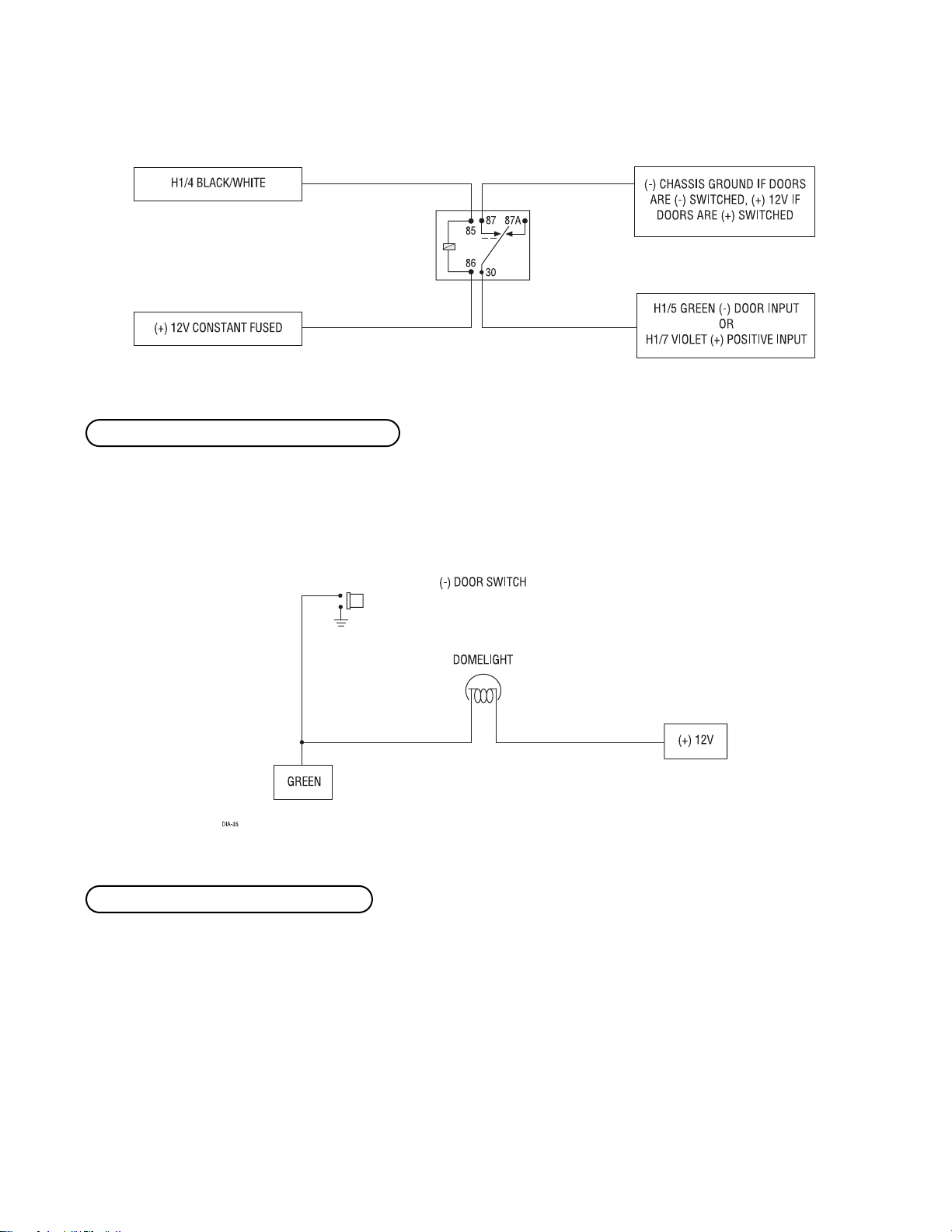
This wire should be connected to the (+) parking light wire. This output is protected with a 10 amp fuse. Never
increase the value of the light flash fuse. If more current is required, use an external relay.
NOTE: When connecting this wire to a (-) parking light wire, a relay is required. See the following
diagram for the relay application.
This wire provides a (-) 200 mA output whenever the transmitter code controlling Channel 3 is received. This
output will continue as long as that transmission is received. Use for options such as 551T Valet Start system,
529T or 530T power window controllers, etc.
IMPORTANT! Never use this wire to drive anything except a relay or a low-current input! The transistorized output can only provide 200 mA of current, and connecting directly to a solenoid, motor,
or other high-current device will cause it to fail.
Connect this wire to the optional domelight supervision relay as shown in the following diagram.
H1/4 BLACK/WHITE (-) domelight supervision relay output
H1/3 WHITE/BLUE (-) channel 3 validity output
H1/2 WHITE (+) light flash output
Page 5
© 2001 Directed Electronics, Inc. Vista, CA 5
IMPORTANT! This output is only intended to drive a relay. It cannot be connected directly to the
domelight circuit, as the output cannot support the current draw of one or more light bulbs.
Most vehicles use negative door trigger circuits. Connect the green wire to a wire which shows ground when any
door is opened. In vehicles with factory delays on the domelight circuit, there is usually a wire that is unaffected
by the delay circuitry. This wire will report Zone 3.
This input will respond to a negative input with an instant trigger. It is ideal for hood and trunk pins and will
report on Zone 1. It can also be used with 506T Glass Breakage Sensor, as well as other DEI single stage sensors.
The H1/6 BLUE instant trigger wire can be used to shunt sensors during operation, using the auxiliary channels.
When any of the auxiliary channels are transmitted, the H1/6 BLUE wire monitors for a ground. If a ground is
detected within 5 seconds of transmission, the sensors and the instant trigger input on the BLUE wire will be
shunted until 5 seconds after the ground is removed. This allows the customer to access the trunk, remote start
the vehicle or roll the windows down without first disarming the alarm. (See Bypassing Sensor Inputs section of
this guide.)
H1/6 BLUE (-) instant trigger, zone 1
H1/5 GREEN (-) door trigger input, zone 3
Page 6

6 © 2001 Directed Electronics, Inc. Vista, CA
This type of dome circuit is used in many Ford vehicles. Connect the violet wire to a wire that shows (+)12V when
any door is opened, and ground when the door is closed. This wire will report Zone 3.
Remove any paint and connect this wire to bare metal, preferably with a factory bolt rather than your own screw.
(Screws tend to either strip or loosen with time.) We recommend grounding all your components, including the
siren, to the same point in the vehicle.
Connect this wire to an ignition source. This input must show (+)12V with the key in run position and during
cranking. This wire will report Zone 5.
CAUTION! Make sure that the H1/9 wire cannot be shorted to the chassis at any point.
H1/9 YELLOW (+) ignition input, zone 5
H1/8 BLACK (-) chassis ground input
H1/7 VIOLET (+) door trigger input, zone 3
Page 7

© 2001 Directed Electronics, Inc. Vista, CA 7
Connect this to the red wire of the siren. Connect the black wire of the siren to (-) chassis ground, preferably at
the same point you connect the control module’s black ground wire.
Before connecting this wire, remove the supplied fuse. Connect to the positive battery terminal or the constant
12V supply to the ignition switch.
NOTE: Always use a fuse within 12 inches of the point you obtain (+)12V power. Do not use the
15A fuse in the harness for this purpose. This fuse protects the module itself.
When the system receives the code controlling Channel 2, for longer than 1.5 seconds, the red/white wire will
supply an output as long as the transmission continues. This is often used to operate a trunk/hatch release or
other relay-driven function.
IMPORTANT! Never use this wire to drive anything but a relay or a low-current input! The transistorized output can only supply 200 mA of current. Connecting directly to a solenoid, motor, or other
high-current device will cause it to fail.
H1/12 RED/WHITE (-) 200 mA channel 2 output
H1/11 RED (+)12V constant power input
H1/10 BROWN (+) siren output
Page 8

8 © 2001 Directed Electronics, Inc. Vista, CA
starter kill harness (H2) wire connection guide
______
______
Use one of these wire as a starter kill input and the other as a starter kill output wire (these wires are inter-
changeable).
plug-in LED and valet/program switch
The LED and the Valet/Program switch both plug into the control module. The status LED plugs into the white
two-pin port, while the Valet/Program switch should be plugged into the blue two-pin port. The status LED and
Valet/Program switch each fit into
9
/32-inch holes.
Status LED Valet/Program Switch
H2/1 and H2/2 BLACK starter kill wires
BLACK STARTER KILL OUTPUT
BLACK STARTER KILL INPUT
H2/1
H2/2
Page 9

© 2001 Directed Electronics, Inc. Vista, CA 9
transmitter/receiver learn routine
The system comes with two transmitters that have been taught to the receiver. Use the following learn routine
to add transmitters to the system or to change button assignments if desired.
The Valet/Program button, plugged into the blue port, is used for programming. There is a basic sequence to
remember whenever programming this unit: Door, Key, Choose, Transmit and Release.
1. Open a door. (The GREEN wire, H1/5, or the VIOLET, H1/7 must be connected.)
2. Key. Turn the ignition on. (The H1/9 YELLOW switched ignition input must be connected.)
3. Select the receiver channel. Press and release the Valet/Program switch the number of
times necessary to access the desired channel. Once you have selected a channel, press
and HOLD the Valet/Program switch once more. The siren will chirp and the LED will blink
the number of times corresponding to the channel that has been accessed.
NOTE: If adding a remote, a button must be taught to Channel One prior to programming other
channels.
NOTE: If any transmitter button from a known transmitter is programmed to Channel Five, all transmitters will be erased from memory. This is useful in cases when one of the customer's transmitters
is lost or stolen. This will erase any lost or stolen transmitters from the system's memory. It can
also be used to start from scratch if the transmitter buttons were programmed incorrectly.
CHANNEL PRESS AND RELEASE
NUMBER THE VALET/PROGRAM SWITCH TO PROGRAM FUNCTION
1 One Time Arm/Disarm/Panic
2 Two Times Channel 2
3 Three Times Channel 3
4 Four Times Auto Learn Standard Configuration*
5 Five Times Delete all transmitters
*NOTE: For Auto Learn Standard Configuration, see Transmitter Configuration section
of this guide.
Page 10

10 © 2001 Directed Electronics, Inc. Vista, CA
4. Press the transmitter button. While HOLDING the Valet/Program switch, press the trans-
mitter button that you wish to assign to that channel. The unit will chirp indicating
successful programming. You cannot teach a transmitter button to the system more than once.
NOTE: For Channel 4, press Button I to program the Auto Learn Standard Configuration on a twobutton transmitter. If programming an optional four-button transmitter, then press Button I to
assign the standard configuration to Buttons I and II; or press Button III to assign the standard
configuration to Buttons III and IV, instead.
5. Release. Once the code is learned, the Valet/Program button can be released.
You can advance from one channel to another by releasing the Valet/Program button and tapping it to advance
channels and then HOLDING it. For example, if you want to program Channel Three after programming Channel
One, release the Valet/Program button. Press it twice and release it to advance to Channel Three. Then press it once
more and HOLD it. The siren will chirp three times to confirm it is ready to receive the code from the transmitter.
Learn Routine will be exited if any of the following occurs:
■ The ignition is turned off.
■ The vehicle door is closed.
■ The Valet/Program button is pressed too many times.
■ More than 15 seconds elapses between steps.
One long chirp indicates that Learn Routine has been exited.
transmitter configuration
The transmitters can be programmed with the Standard Configuration by using the Channel 4 Auto Learn Standard
Configuration function in the Transmitter/Receiver Learn Routine. When programmed for Standard Configuration,
the transmitter buttons are assigned to the following functions:
Button I (III*) ....................................operates............................................Arm/Disarm/Panic
Button II (IV*) ....................................operates............................................Channel Two
Buttons I and II (III and IV*) ...............operate .............................................Channel Three
*NOTE: If using an optional four-button remote, the Standard Configuration may alternately be taught to Buttons III and IV by pressing Button III in Step 4 of the
Transmitter/Receiver Learn Routine.
Page 11

© 2001 Directed Electronics, Inc. Vista, CA 11
operating settings learn routine
Many of the operating settings of this unit are programmable. They can be changed whenever necessary through
the Operating Settings Learn Routine. The Valet/Program push-button switch, plugged into the blue port, is used
together with a programmed transmitter to change the settings.
The Operating Settings Learn Routine dictates how the unit operates. It is possible to access and change any of
the feature settings using the Valet/Program switch.
To enter the System Features Learn Routine:
1. Open a door. (The GREEN wire, H1/5, or the VIOLET, H1/7 must be connected.)
2. Ignition. Turn the ignition on, then back off. (The H1/9 YELLOW switched ignition input
must be connected.)
2. Choose. Within 10 seconds, press and release the Valet/Program switch the number of
times corresponding to the feature number you want to program (see the Features Menu
section of this guide). The LED ON settings listed in the Features Menu table are the factory
default settings.
Once the Valet/Program switch has been pressed and released the number of times corre-
sponding to the feature you wish to program, press it once more and HOLD it. After one
second, the LED will flash to indicate which feature you have accessed. For example, groups
of five flashes would indicate access to Feature 5. The siren will also chirp five times.
4. Transmit. While HOLDING the Valet/Program switch, you can select the desired feature set-
tings using the remote transmitter. As shipped, the unit is configured to the default LED
ON settings. Pressing Button I while HOLDING down the Valet/Program switch will program
a feature to the LED ON setting. The siren will chirp once to indicate the one-chirp setting
has been selected. Pressing Button II while HOLDING down the Valet/Program switch will
change a setting to the LED OFF setting. The siren will chirp twice indicating that the LED
OFF setting has been selected.
5. Release. Release the Valet/Program switch.
Page 12

12 © 2001 Directed Electronics, Inc. Vista, CA
You can advance from feature to feature by pressing and releasing the Valet/Program switch the number of times
necessary to get from the feature you just programmed to the feature you wish to access. For example, if you
just programmed Feature 1 and you want to program Feature 2:
1. Release the Valet/Program switch.
2. Press and release the Valet/Program switch once to advance from Feature 1 to Feature 2.
3. Press the Valet/Program switch once more and HOLD it.
4. The siren will chirp two times to confirm that you have accessed Feature 2.
To exit the learn routine, do one of the following:
1. Close the open vehicle door.
2. Turn the ignition on.
3. No activity for longer than 15 seconds.
4. Press the Valet/Program switch too many times.
features menu
FEATURE DEFAULT LED ON SETTINGS LED OFF SETTINGS
NUMBER (PRESS TRANSMITTER BUTTON I) (PRESS TRANSMITTER BUTTON II)
1 Active Arming Passive Arming
2 Confirmation Chirps ON Confirmation Chirps OFF
3 No Feature
4 No Feature
5 No Feature
6 No Feature
7 Code Hopping ON Code Hopping OFF
NOTE: Factory defaults are indicated in bold type.
to exit the learn routine
to access another feature
Page 13

© 2001 Directed Electronics, Inc. Vista, CA 13
feature descriptions
1 ACTIVE/PASSIVE ARMING: When active arming is selected, the system will only arm when the transmitter is
used. When set to passive arming, the system will arm automatically 30 seconds after the last door is closed.
Passive arming is indicated by the rapid flashing of the LED when the last protected entry point is closed.
2 CONFIRMATION CHIRPS ON/OFF: This feature controls the chirps that confirm the arming and disarming of
the system.
3 NO FEATURE
4 NO FEATURE
5 NO FEATURE
6 NO FEATURE
7 CODE HOPPING ON/OFF: This system features Code Hopping as an option. Code Hopping is a feature that uses
a mathematical formula to change the system’s code each time the transmitter and receiver communicate. This
makes the group of bits or "word" from the transmitter very long. The longer the word is, the easier it is to block
its transmission to the unit. Disabling the Code Hopping feature lets the receiver ignore the Code Hopping part
of the transmitted word. As a result, the unit may have better range with Code Hopping off.
bypassing sensor inputs
There are times when you need to temporarily bypass all sensor inputs to the unit, such as when remote starting
the vehicle. Anytime an auxiliary channel output is used, all inputs are bypassed for 5 seconds. During the
5-second bypass period, ground can be supplied to the H1/6 Blue wire without triggering the unit. When the
5-second bypass period ends, if the unit sees ground on the H1/6 Blue wire, all trigger inputs except the door
trigger input will remain bypassed until 5 seconds after ground is removed from the BLUE wire. This can be done
using the status output of a 551T remote start unit as shown below:
Page 14

14 © 2001 Directed Electronics, Inc. Vista, CA
nuisance prevention circuitry
Nuisance Prevention Circuitry (NPC) requires that you change the way you test the system, as NPC will bypass an
input zone for 60 minutes. If the system “sees” the same zone trigger three times AND the triggers are spaced
less than an hour apart, the system will bypass that input zone for 60 minutes. If that zone does not attempt to
trigger the system during the 60-minute bypass period, the zone’s monitoring will begin again at the end of the
hour. If it does attempt to trigger while bypassed, the 60-minute bypass starts over again.
Disarming and rearming the system does not reset NPC. The only way to reset NPC is for the 60 minutes to pass,
without a trigger, or for the ignition to be turned on. This allows the system to be repeatedly triggered, disarmed
and rearmed, and still allow NPC to bypass a faulty zone.
When disarming the system, 5 chirps indicate that NPC is activated. The LED will report the zone that has been
bypassed. (See Table of Zones section of this guide.)
table of zones
When using the Diagnostic functions, use the Table of Zones to see which input has triggered the system. It is
also helpful in deciding which input to use when connecting optional sensors and switches.
ZONE NO. TRIGGER TYPE INPUT DESCRIPTION
1 Instant H1/6 BLUE wire. Connects to optional hood/trunk pins.
2 Multiplexed Second-stage of on-board shock sensor.
3 Two-stage, progresses from Door switch circuit. H1/5 GREEN or H1/7 VIOLET.
warning to full alarm
5 Two-stage, progresses from Ignition. H1/9 YELLOW.
warning to full alarm
NOTE: The Warn Away response does not report on the LED.
Page 15

© 2001 Directed Electronics, Inc. Vista, CA 15
troubleshooting
■ Door input does not immediately trigger full alarm. Instead, first I hear chirps for 3 seconds:
That's how the progressive two-stage door input works! This is a feature of this system. This is an instant trigger,
remember, since even if the door is instantly re-closed, the progression from chirps to constant siren will continue.
■ Closing the door triggers the system, but opening the door does not:
Have you correctly identified the type of door switch system? This often happens when the wrong door input has
been used. (See H1/5 GREEN Door Trigger Input, Primary Harness Wire Connection Guide section of this guide.)
■ System will not passively arm until it is remotely armed and then disarmed:
Are the door inputs connected? Is the H1/6 blue wire connected to the door trigger wire in the vehicle? Either
the H1/5 green or the H1/7 violet should be used instead. (See Primary Harness Wire Connection Guide section
of this guide.)
■ Door input does not respond with the progressive trigger, but with immediate full alarm:
Does the Status LED indicate that the trigger was caused by the shock sensor? (See Table of Zones section of this
guide.) The shock sensor, if set to extreme sensitivity, may be detecting the door unlatching before the door
switch sends its signal. Reducing the sensitivity can solve this problem.
■ The Valet/Program switch does not work:
Is it plugged into the correct socket? (See Plug-In LED and Valet/Program Switch section of this guide.)
■ The status LED does not work:
You've probably guessed already, but here goes: is it plugged in? Is the LED plugged into the correct socket? (See
Plug-In LED and Valet/Program Switch section of this guide.)
Page 16

16 © 2001 Directed Electronics, Inc. Vista, CA
 Loading...