


Model 100
Installation Guide
© 2000 Directed Electronics, Inc. Vista, CA N411R 3-00
Downloaded from: http://www.guardianalarms.net

table of contents
What Is Included . . . . . . . . . . . . . . . . . . . . . 3
Primary Harness (H1), 12-Pin Connector . . . . . 4
Relay Harness (H2), 6-Pin Connector . . . . . . . 4
Primary Harness (H1) Wire Connection Guide. . 5
Plug-In LED and Valet/Program Switch . . . . . . 10
Relay Harness (H2) Wire Connection Guide . . 11
Identifying the Door Lock System. . . . . . . . 11
At the Switch. . . . . . . . . . . . . . . . . . . . . 12
Type A Door Locks. . . . . . . . . . . . . . . . . . 12
Type B Door Locks. . . . . . . . . . . . . . . . . . 13
Testing Reversing Polarity Systems . . . . . . . 14
Type C Door Locks . . . . . . . . . . . . . . . . . . 15
Type D Door Locks. . . . . . . . . . . . . . . . . . 16
Type E Door Locks . . . . . . . . . . . . . . . . . . 17
Type F Door Locks . . . . . . . . . . . . . . . . . . 18
Type G Door Locks. . . . . . . . . . . . . . . . . . 19
Type H Door Locks . . . . . . . . . . . . . . . . . 20
Transmitter/Receiver Learn Routine. . . . . . . . 21 To advance from one channel to another . . . 22 To exit learn routine . . . . . . . . . . . . . . . . 22
Transmitter Configuration . . . . . . . . . . . . . . 22
Standard Configuration. . . . . . . . . . . . . . . 22
Operating Settings Learn Routine . . . . . . . . . 23 To access another feature . . . . . . . . . . . . . 24 To exit the learn routine. . . . . . . . . . . . . . 24
Features Menu . . . . . . . . . . . . . . . . . . . . . . 24
Feature Descriptions . . . . . . . . . . . . . . . . . . 25
Troubleshooting . . . . . . . . . . . . . . . . . . . . . 26
Bitwriter™, Code Hopping™, DEI®, Doubleguard®, ESP™, FailSafe®, Ghost Switch™, Learn Routine™, NiteLite®, Nuisance Prevention Circuitry®, NPC®, Revenger®, Silent Mode™, Soft Chirp®, Stinger®, Valet®, Vehicle Recovery System®, VRS®, and Warn Away® are all Trademarks or Registered Trademarks of Directed Electronics, Inc.
2 |
© 2000 Directed Electronics, Inc. Vista, CA |
what is included
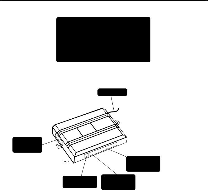
■The control module (see diagram)
■Two two-button remote transmitters
■The plug-in status LED
■The plug-in Valet®/Program switch
■The 12-pin primary harness
■The 6-pin door lock harness
Antenna
6-pin Door
Lock Harness
Port
12-Pin Primary
Harness (H1)
Port
2-pin White
2-Pin Blue
LED Port
Valet/Program
Port
© 2000 Directed Electronics, Inc. Vista, CA |
3 |

primary harness (H1), 12-pin connector
The primary harness is the standard 12-pin harness used by DEI security systems. Two pins in the harness do not have wires (H1/5 and H1/7). The functions of all the wires that are used in the primary harness are outlined in this section. The wire connections are described in the Primary Harness (H1) Wire Connection Guide section.
|
______ |
|
|
H1/1 |
ORANGE |
(-) 500 mA GROUND-WHEN-ARMED OUTPUT |
|
|
______ |
|
|
|
|
|
|
H1/2 |
WHITE |
(+) LIGHT FLASH OUTPUT |
|
|
______ |
|
|
|
|
|
|
H1/3 |
WHITE/BLUE |
(-) 200 mA CHANNEL 3 VALIDITY OUTPUT |
|
|
______ |
|
|
|
|
|
|
H1/4 |
BLACK/WHITE |
(-) 200 mA DOMELIGHT SUPERVISION OUTPUT |
|
H1/5 |
|
|
|
|
|
|
|
H1/6 |
______ |
|
|
BLUE |
(-) 200 mA SECOND UNLOCK OUTPUT |
||
H1/7 |
|
|
|
|
|
|
|
H1/8 |
______ |
|
|
BLACK |
(-) CHASSIS GROUND INPUT |
||
H1/9 |
______ |
|
|
|
|
||
YELLOW |
(+) SWITCHED IGNITION INPUT |
||
H1/10 |
______ |
|
|
|
|
||
BROWN |
(-) HORN HONK OUTPUT |
||
H1/11 |
______ |
|
|
|
|
||
RED |
(+) CONSTANT POWER INPUT |
||
H1/12 |
______ |
|
|
|
|
||
RED/WHITE |
(-) 200 mA CHANNEL 2 VALIDITY OUTPUT |
||
|
|
|
|
relay harness (H2), 6-pin connector
|
______ |
|
|
H2/A |
WHITE/BLACK |
LOCK #87A NORMALLY CLOSED |
|
H2/B |
______ |
|
|
|
|
||
GREEN/BLACK |
LOCK #30 COMMON (OUTPUT) |
||
H2/C |
______ |
|
|
|
|
||
VIOLET/BLACK* |
LOCK #87 NORMALLY OPEN (INPUT) |
||
H2/D |
______ |
|
|
|
|
||
BROWN/BLACK |
UNLOCK #87A NORMALLY CLOSED |
||
H2/E |
______ |
|
|
|
|
||
BLUE/BLACK |
UNLOCK #30 COMMON (OUTPUT) |
||
H2/F |
______ |
|
|
|
|
||
VIOLET* |
UNLOCK #87 NORMALLY OPEN (INPUT) |
||
|
|
|
|
*NOTE: VIOLET and VIOLET/BLACK are common at the fuse holder.
4 |
© 2000 Directed Electronics, Inc. Vista, CA |
primary harness (H1) wire connection guide
H1/1 ORANGE (-) ground-when-armed output
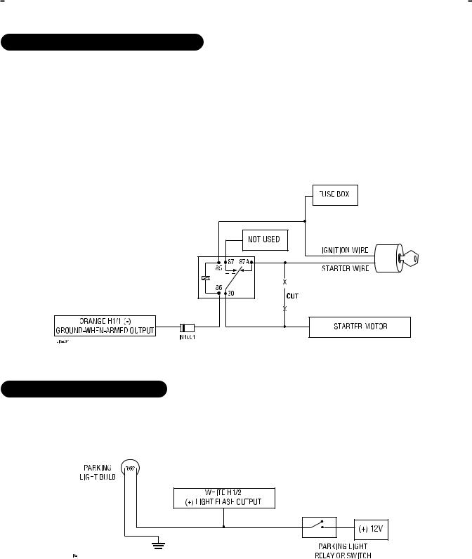
This wire supplies a (-) 500 mA ground as long as the system is armed. This output ceases as soon as the system is disarmed. The orange wire can be used to control an optional starter kill relay or a DEI 8617.
NOTE: If connecting the orange wire to control another module, such as a 529T or 530T window controller, a 1 amp diode (type 1N4004) will be required. Insert the diode as shown below.
IMPORTANT! Never interrupt any wire other than the starter wire.
H1/2 WHITE (+) light flash output
This wire should be connected to the (+) parking light wire. This output is protected with a 10 amp fuse. Never increase the value of the light flash fuse. If more current is required, use an external relay.
© 2000 Directed Electronics, Inc. Vista, CA |
5 |
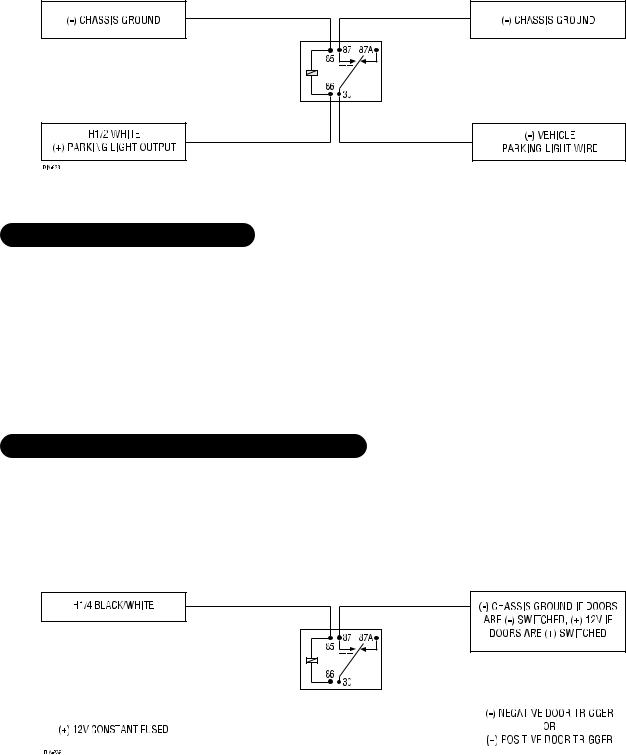
NOTE: When connecting this wire to a (-) parking light wire, a relay is required. See the following diagram for the relay application.
H1/3 WHITE/BLUE (-) channel 3 output
This wire provides a (-) 200 mA output whenever the transmitter code controlling Channel 3 is received. This
output will continue as long as that transmission is received. Use for options such as 551T Valet® Start system,
529T or 530T power window controllers, etc.
IMPORTANT! Never use this wire to drive anything except a relay or a low-current input! The transistorized output can only provide 200 mA of current, and connecting directly to a solenoid, motor, or other high-current device will cause it to fail.
H1/4 BLACK/WHITE (-) domelight supervision relay output
Connect this wire to the optional domelight supervision relay as shown below:
IMPORTANT! This output is only intended to drive a relay. It cannot be connected directly to the domelight circuit, as the output cannot support the current draw of one or more light bulbs.
6 |
|
|
|
|
|
|
|
|
|
|
|
|
|
|
|
|
|
|
|
|
|
|
|
|
|
|
|
|
|
|
|
|
|
|
|
|
|
|
|
|
|
|
|
|
|
|
|
|
|
|
|
|
|
|
|
|
|
|
|
|
|
|
|
|
|
|
|
|
|
|
|
|
|
|
|
|
|
|
|
|
|
|
|
|
|
|
|
|
|
|
|
|
|
|
|
|
|
|
|
|
|
|
|
|
|
|
|
|
|
|
|
|
|
|
|
|
|
|
|
|
|
|
|
|
|
|
|
|
|
|
|
|
|
|
|
|
© 2000 Directed Electronics, Inc. Vista, CA |
|||||
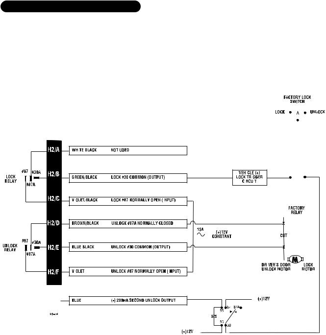
H1/6 BLUE (-) 200mA second unlock output
This output is used for progressive door unlock. A progressive unlock system unlocks the driver's door when the unlock (disarm) button is pressed and unlocks the passenger doors if the unlock (disarm) button is pressed again within 15 seconds after unlocking the driver's door. The BLUE wire outputs a low current (-) pulse on the second press of the unlock button of the transmitter. This negative unlock output is used to unlock the passenger doors.
Driver’s Door Unlock Only (Type A)
|
|
|
|
|
|
|
|
|
|
|
|
|
|
|
|
|
|
|
|
|
|
|
|
|
|
|
|
|
|
|
|
|
|
|
|
|
|
|
|
|
|
|
|
|
|
|
|
|
|
|
|
|
|
|
|
|
|
|
|
|
|
|
|
|
|
|
|
|
|
|
|
|
|
|
|
|
|
|
|
|
|
|
|
|
|
|
|
|
|
|
|
|
|
|
|
|
|
|
|
|
|
|
|
|
|
|
|
|
|
|
|
|
|
|
|
|
|
|
|
|
|
|
|
|
|
|
|
|
|
|
|
|
|
|
|
|
|
|
|
|
|
|
|
|
|
|
|
|
|
|
|
|
|
|
|
|
|
|
|
|
|
|
|
|
|
|
|
|
|
|
|
|
|
|
|
|
|
|
|
|
|
|
|
|
|
|
|
|
|
|
|
|
|
|
|
|
|
|
|
|
|
|
|
|
|
|
|
|
|
|
|
|
|
|
|
|
|
|
|
|
|
|
|
|
|
|
|
|
|
|
|
|
|
|
|
|
|
|
|
|
|
|
|
|
|
|
|
|
|
|
|
|
|
|
|
|
|
|
|
|
|
|
|
|
|
|
|
|
|
|
|
|
|
|
|
|
|
|
|
|
|
|
|
|
|
|
|
|
|
|
|
|
|
|
|
|
|
|
|
|
|
|
|
|
|
|
|
|
|
|
|
|
|
|
|
|
|
|
|
|
|
|
|
|
|
|
|
|
|
|
|
|
|
|
|
|
|
|
|
|
|
|
|
|
|
|
|
|
|
|
|
|
|
|
|
|
|
|
|
|
|
|
|
|
|
|
|
|
|
|
|
|
|
|
|
|
|
|
|
|
|
|
|
|
|
|
|
|
|
|
|
|
|
|
|
|
|
|
|
|
|
|
|
|
|
|
|
|
|
|
|
|
|
|
|
|
|
|
|
|
|
|
|
|
|
|
|
|
|
|
|
|
|
|
|
|
|
|
|
|
|
|
|
|
|
|
|
|
|
|
|
|
|
|
|
|
|
|
|
|
|
|
|
|
|
|
|
|
|
|
|
|
|
|
|
|
|
|
|
|
|
|
|
|
|
|
|
|
|
|
|
|
|
|
|
|
|
|
|
|
|
|
|
|
|
|
|
|
|
|
|
|
|
|
|
|
|
|
|
|
|
|
|
|
|
|
|
|
|
|
|
|
|
|
|
|
|
|
|
|
|
|
|
|
|
|
|
|
|
|
|
|
|
|
|
|
|
|
|
|
|
|
|
|
|
|
|
|
|
|
|
|
|
|
|
|
|
|
|
|
|
|
|
|
|
|
|
|
|
|
|
|
|
|
|
|
|
|
|
|
|
|
|
|
|
|
|
|
|
|
|
|
|
|
|
|
|
|
|
|
|
|
|
|
|
|
|
|
|
|
|
|
|
|
|
|
|
|
|
|
|
|
|
|
|
|
|
|
|
|
|
|
|
|
|
|
|
|
|
|
|
|
|
|
|
|
|
|
|
|
|
|
|
|
|
|
|
|
|
|
|
|
|
|
|
|
|
|
|
|
|
|
|
|
|
|
|
|
|
|
|
|
|
|
|
|
|
|
|
|
|
|
|
|
|
|
|
|
|
|
|
|
|
|
|
|
|
|
|
|
|
|
|
|
|
|
|
|
|
|
|
|
|
|
|
|
|
|
|
|
|
|
|
|
|
|
|
|
|
|
|
|
|
|
|
|
|
|
|
|
|
|
|
|
|
|
|
|
|
|
|
|
|
|
|
|
|
|
|
|
|
|
|
|
|
|
|
|
|
|
|
|
|
|
|
|
|
|
|
|
|
|
|
|
|
|
|
|
|
|
|
|
|
|
|
|
|
|
|
|
|
|
|
|
|
|
|
|
|
|
|
|
|
|
|
|
|
|
|
|
|
|
|
|
|
|
|
|
|
|
|
|
|
|
|
|
|
|
|
|
|
|
|
|
|
|
|
|
|
|
|
|
|
|
|
|
|
|
|
|
|
|
|
|
|
|
|
|
|
|
|
|
|
|
|
|
|
|
|
|
|
|
|
|
|
|
|
|
|
|
|
|
|
|
|
|
|
|
|
|
|
|
|
7 |
|||||||||||
|
|
|
|
|
|
|
|
|
|
|
|
|
|
|
|
|
|
|
|
|
|
|
|
|
|
|
|
|
|
|
||||||||||||
|
|
|
|
|
|
|
|
|
|
|
|
|
|
|
|
|
|
|
|
|
|
|
|
|
|
|
|
|
|
|
||||||||||||
|
|
|
|
|
|
|
|
|
|
|
|
|
|
|
|
|
|
|
|
|
|
|
|
|
|
|
|
|
|
|
||||||||||||
|
|
|
|
|
|
|
|
|
|
|
|
|
|
|
|
|
|
|
|
|
|
|
|
|
|
|
|
|
|
|
||||||||||||
|
|
|
|
|
|
|
|
|
|
|
|
|
|
|
|
|
|
|
|
|
|
|
|
|
|
|
|
|
|
|
||||||||||||
|
|
|
|
|
|
|
|
|
|
|
|
|
|
|
|
|
|
|
|
|
|
|
|
|
|
|
|
|
|
|
||||||||||||
|
|
|
|
|
|
|
|
|
|
|
|
|
|
|
|
|
|
|
|
|
|
|
|
|
|
|
|
|
|
|
||||||||||||
|
|
|
|
|
|
|
|
|
|
|
|
|
|
|
|
|
|
|
|
|
|
|
|
|
|
|
|
|
|
|
||||||||||||
|
|
|
|
|
|
|
|
|
|
|
|
|
|
|
|
|
|
|
|
|
|
|
|
|
|
|
|
|
|
|
||||||||||||
|
|
|
|
|
|
|
|
|
|
|
|
|
|
|
|
|
|
|
|
|
|
|
|
|
|
|
|
|
|
|
||||||||||||
|
|
|
|
|
|
|
|
|
|
|
|
|
|
|
|
|
|
|
|
|
|
|
|
|
|
|
|
|
|
|
||||||||||||
© 2000 Directed Electronics, Inc. Vista, CA |
||||||||||||||||||||||||||||||||||||||||||

Driver’s Door Unlock Only (Type B)
H1/8 BLACK (-) chassis ground connection
Connect the H1/8 BLACK wire to bare metal, preferably with a factory bolt rather than your own screw (screws tend to either strip or loosen with time). We recommend grounding all your components to the same point in the vehicle.
8 |
|
|
|
|
|
|
|
|
|
|
|
|
|
|
|
© 2000 Directed Electronics, Inc. Vista, CA |
|||
|
|
|
|
|
|
||||
|
|
|
|
|
|
||||
|
|
|
|
|
|
||||
|
|
|
|
|
|
||||
|
|
|
|
|
|
||||
 Loading...