

Page 1

OWNER’S
MANUAL.
You can rely o n Def y
PREMIUM
CHIMNEY
HOOD
600 PREMIUM
CHIMNEY HOOD
DCH284 IN STAINLESS STEEL
DCH285 IN BLACK
900 PREMIUM
CHIMNEY HOOD
DCH260 IN STAINLESS STEEL
DCH261 IN BLACK
The manufacturer strives for
continuous improvements.
For this reason, the text
and illustrations in this book
are subject to change
without notice.
Part Number 066044
PLEASE READ THESE INSTRUCTIONS
CAREFULLY
BEFORE INSTALLING AND OPERATING.
INDEX
2 Description.
2 Before use.
2 Safety advice.
2 Electrical connection.
3 Preparing for installation.
3 Recirculating filtered air.
3 Venting air to the outside.
4 Installation.
6 Grease filters.
6 Optional carbon pad filters.
7 Operation.
7 Replacing the light bulbs.
8 Maintenance and cleaning.
9 Owner’s responsibility.
9 Problem check.
9 Service Centres.
10 Warranty.
www.defy.co.za
Page 1
Page 2
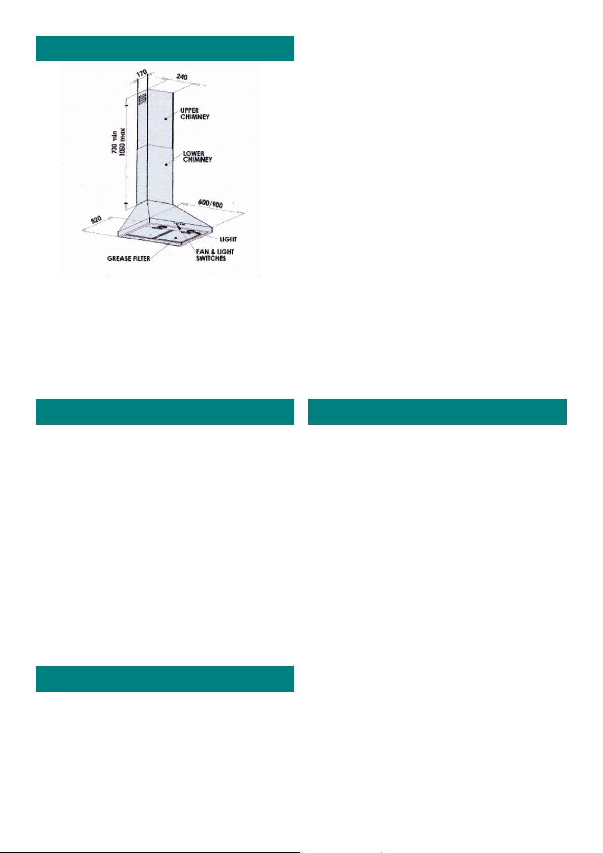
Description.
• The extractor hood fan extracts the
kitchen vapours and passes them through
the grease filter.
• The grease filter absorbs the solid parti-
cles in the cooking vapours, keeping the
kitchen almost free of grease.
Never operate the extractor hood without
•
a grease filter.
• Never leave cooking fat or oil unat-
tended. Overheated fat or oil can easily
catch fire.
• Do not flambé food directly under the ex-
tractor hood. The flames pose the risk of
the grease filter catching fire.( see page 8
Maintenance and cleaning)
• Restrictions apply to the use of the ex-
tractor hood over a solid fuel or gas
stove. (See Preparing for installation on
page 3).
• Switch off the power at the mains in the
event of a fault or when cleaning the extractor hood
• Do not touch any part of the light fittings
while they are in us e as they get very hot
and could cause severe burns.
Before use.
Before using your new extractor hood for
the first time, please read this manual carefully. It contains important information concerning your personal safety as well as on
the use and care of the extractor hood.
• Remove all packaging (except the protec-
tive film on the two chimney sections)
and dispose of it in an environmentally
friendly manner.
• If the extractor hood is damaged in any
way, do not use it. Report the damage to
your dealer, who will take the necessary
corrective action. (Refer to Owner’s responsibility on page 9 of this manual).
Safety advice.
• This extractor hood complies with all
relevant safety regulations.
•
The extractor hood is not intended for use
by young children or infirm persons without supervision.
Electrical connection.
• The extractor hood uses a 220-
250V/50Hz power supply.
• If the mains power cord is damaged, it
must be replaced by a qualified electrician.
• The power cord is located in the chimney
area. Should you require an installation
with no visible wiring, a 15 amp earthed
plug socket should be accessible either in
the ceiling above the extractor hood or on
the wall behind the chimney area.
(A qualified electrician should provide
this facility).
• The extractor hood must be earthed.
The manufacturer and the seller do
not accept responsibility for any damage due to incorrect electrical connection.
• This extractor hood may not be used
with a battery inverter power supply.
Page 2
Page 3
Preparing for installation.
The extractor hood has the ability to either recirculate the filtered air back into
the kitchen, or to vent the filtered air
through an outside wall.
Decide on which option best suits you before commencing with the installation.
• The extractor hood is intended to be
mounted onto a flat perpendicular kitchen
wall capable of supporting the weight of
the hood. (approximately 16 to 26 kg depending on the model).
Tools required for installation:
• An electric drill.
• A 3.5 mm diam. steel drill bit.
• 8mm and 5mm diam. masonry drill bits
• A star screw driver (Posi 2).
• A ratchet with a 10mm socket and a
100mm extension.
• A tape measure, masking tape and a pen-
cil.
ITEM
DESCRIPTION
8mm wall plug
6mm screw
5mm wall plug
5mm screw
Self tapping screw
Slotted washer
QUANTITY
4
6
10
4
Care must be taken during installation not
to obstruct these vents.
No ducting is required for this type of installation.
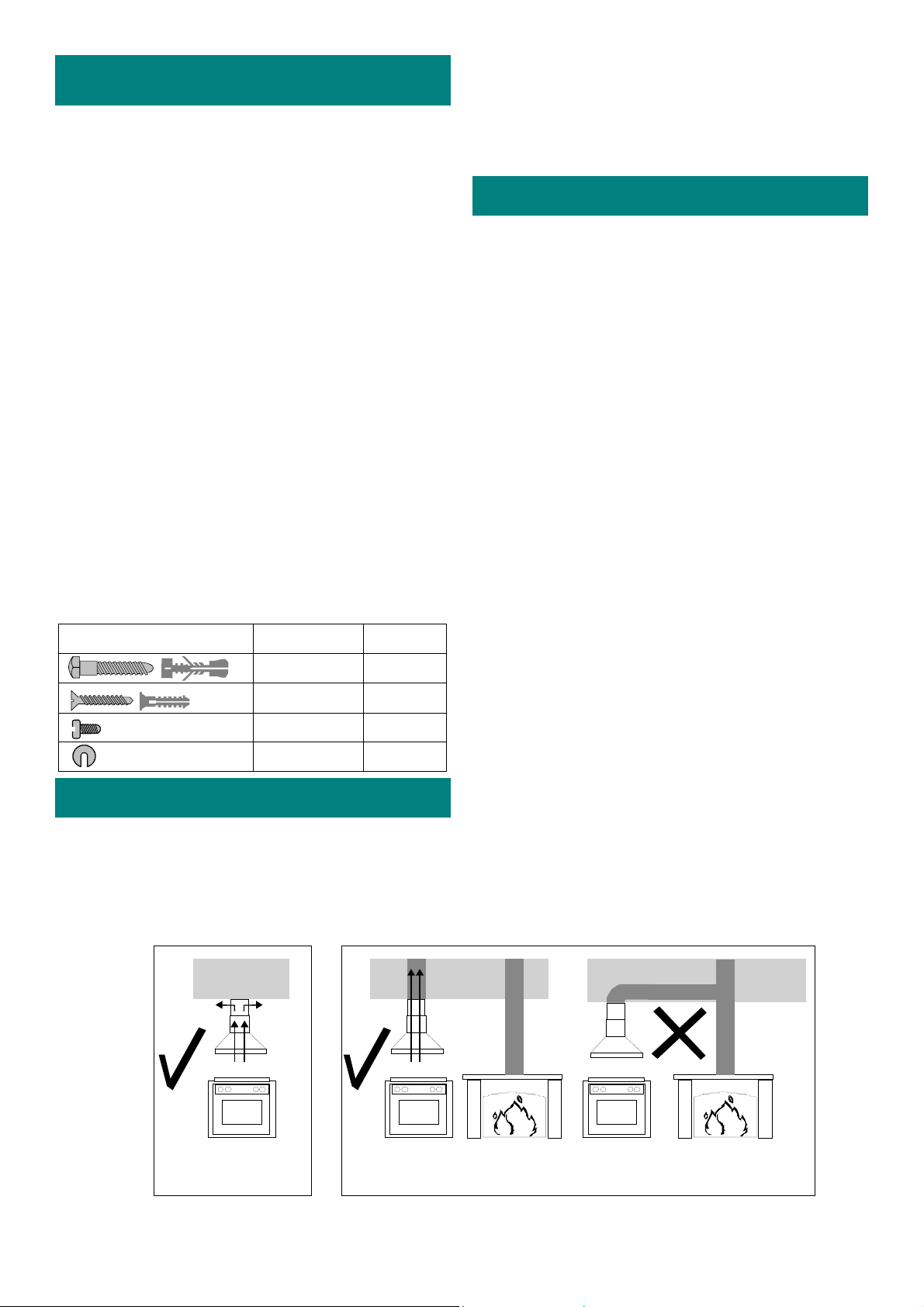
Venting air to the outside.
When discharging the air into a ventilation shaft or directly through the wall
into the open , please take note of the following:
• Exhaust air from the extractor hood
must not be directed into a flue or
chimney which is used for exhausting
the fumes or smoke from other appliances burning gas or fuels.
• Please ensure that regulations concerning the discharge of exhaust air have
been fulfilled. (SABS IEC 60335-2-31).
For optimum extractor hood efficiency use
a short, smooth, round air exhaust pipe with
as few bends as possible A 150mm diameter
exhaust pipe is recommended. Long box
section, narrowed or bent pipes will hinder
performance and increase noise levels.
• Connecting a 150 mm diameter pipe:
Mount the pipe directly onto the air outlet
on the extractor hood.
Recirculating filtered air.
The extractor hood filters out solid particles
before the air is recirculated, via the vents
on the side of the upper chimney, into the
kitchen.
ceiling
Recirculate
filtered air
not shared with another fuel burning appliance.
Exhaust air through a dedicted pipe
Page 3
• Connecting a 125 mm or 100mm diameter pipe: Attach a reducing connec-
tor (available from a specialist retailer)
to the air pipe and then attach to the exhaust-air duct.
ceilingceiling
Page 4

Installation..
Installation sequence;
1. Extractor unit / chimney brackets.
2. Top chimney duct
3. Bottom chimney duct
• Carefully remove the extractor hood and
the components from the packaging.
• Remove the grease filters.
CEILING MOUNTING TEMPLATE
CEILING MOUNTING
CUT TEMPLATE
HOOD TEMPLATE
LINE FROM CENTRE
OF STOVE TO CEILING
Draw a fine vertical line on the wall from
•
the rear-centre of the hob to the ceiling.
• Draw another line, horizontal this time,
where the bottom edge of the hood
should be. (A minimum distance be-
tween the hob and the hood of 750mm
is recommended.)
• Take the template card and separate the
ceiling mounting template from the hood
mounting template by cutting along the
indicated line.
• Using masking tape, stick the ceiling
mounting template to the wall directly
below the ceiling and centered on the
vertical line.
BRACKET POSITION
TOP OF CEILING
750
HORIZONTAL
LINE
• In a similar fashion stick the hood mounting template on the wall ensuring that the
centre-lines line up with those drawn on
the wall.
• Note that the holes marked on the template cater for both 600mm and 900mm
wide models. Please ensure that you only
use those markings relating to the model
you have purchased.
Holes for Triangular 600 are marked
with a (1).
Holes for Triangular 900 are marked
with a (2).
Holes not marked are common to all
models.
• For mounting the chimney brackets, drill
6 holes, 5mm in diameter and 45mm deep
into the wall as indicated on the mounting
template.
• For mounting the extractor hood, drill 4
holes, 8mm in diameter and 60mm deep
as indicated on the mounting template.
• Once all the holes have been drilled the
templates must be removed.
• Push the 5mm Dia. wall plugs through the
holes in the chimney mounting brackets.
Insert the plugs into the drilled holes together with the chimney mounting bracket
and fasten securely.
• Push the 8mm Dia. wall plugs into the
8mm Dia. holes ensuring that they are
flush with the wall.
• Partially screw two 6mm Dia. screws into
the two top wall plugs leaving them to
protrude about 10mm.
• Lift and hook the extractor hood over and
onto the two protruding screws through
the key-hole slots provided at the top of
the extractor hood frame.
• Insert the other two 6mm Dia. screws
through the holes inside the extractor
hood housing and into the 8mm Dia wall
plugs.
• Align the extractor hood with the centre
and horizontal lines before tightening all
four 6mm screws.
Page 4
Page 5
Before fitting the chimneys, connect up
the outlet ducting (if required) and insert
the fitted plug into the wall socket.
• Remove the protective film from the
chimney ducting taking care not to damage the polished stainless steel surface.
• Fit the upper chimney duct section (the
one with louvre outlets) to the ceiling
mounting bracket using the screws supplied.
• Fit the lower chimney duct to the lower
wall mounting bracketand tighten the six
screws on the inside of the extractor hood
• Drill 3.5mm Dia. holes through the top
holes in the bottom chimney and through
the lower end of the top chimney duct.
• Fasten the two chimneys to the centre
chimney bracket.
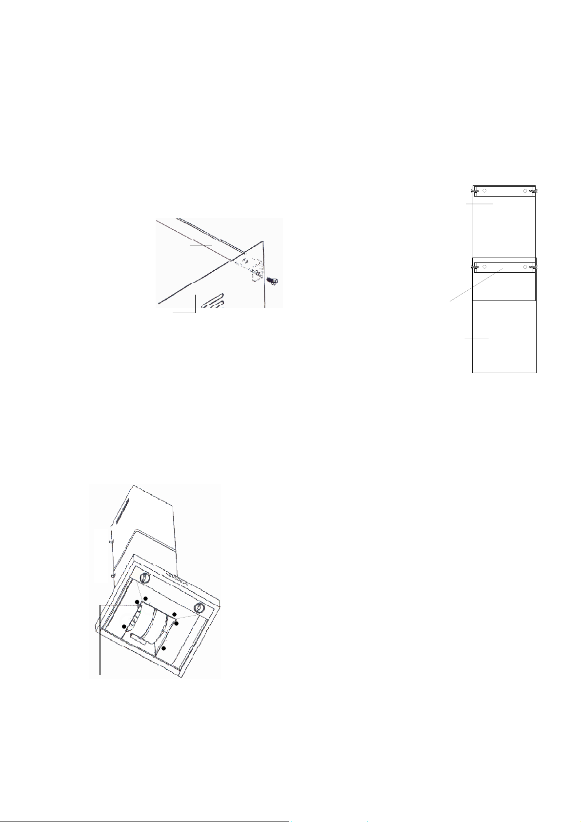
Top chimney duct
CEILING M OUNTING BRACKET
TOP CHIMNEY DUCT
The lower duct fits over the extractor
•
hood motor assembly and over the upper
duct. Take care not to scratch or damage
the hood and upper duct surfaces.
• Loosely attach the lower duct bottom
edge to the hood by four self tapping
screws through four holes on the inside
of the extractor hood .
Drill two 3.5mm Diameter
holes and secure two chimney
ducts to mounting bracket.
Mounting bracket
Bottom chimney duct
INSERT 6 SELF TAPPING SCREWS
Page 5
Page 6

Grease filters.
• Remove the plastic outer protective lining on the grease filters before fitting
them to the extractor hood.
• To fit the filters, engage the two lugs at
the rear of each filter into the rectangular
slots of the extractor hood frame, lift the
filter and press the handle catch inwards .
• Engage the filter and release the catch.
• To remove the filter, for cleaning pur-
poses, reverse the procedure described
above.
STEEL ROD REMOVED
Optional Carbon pad filters.
• Carbon pad filters assist in removing any
unwanted cooking odours from the atmosphere.
• If your installation ducts filtered air to the
outside, the carbon pad filters are not required.
• Should you require them, factory ap-
proved, carbon pad filters and installation
kits may be purchased from your nearest
Defy service Centre or their authorised
agents.
STEEL ROD IN PLACE
GREASE FILTER
CARBON PAD FILTER
Page 6
Page 7
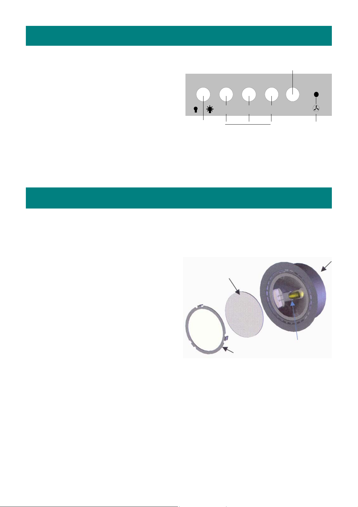
Operation.
• Select the fan speed you require.
• Push button ‘3’ for high extraction level.
• Push button ‘2’ for medium.
• Push button ‘1’ for low.
• The fan indicator light will glow when
the fan is operating.
• To switch the fan off, push the motor
speed OFF button ‘0’.
• If required, you may illuminate the
cooking area by switching the hood
lights on.
• Leave the hood running for a short pe-
riod after the cooking has been completed to clear any smoke and odours.
Replacing the light bulbs.
• Switch off the electricity supply.
• If the bulb has recently failed, it
might still be very hot. Allow the glass
cover to cool before attempting to replace the bulb.
• Hold the glass cover and unclip the re-
taining ring. Be careful not to let the
glass cover fall.
• Replace the light bulb with a commer-
cially available OSRAM 12V 20W
(64425) or equivalent bulb.
• Fit the glass cover and replace the re-
taining ring.
• Switch on the electricity supply.
Lights
on/ off
Glass cover
Fan speed
Retaining ring
Motor speed
Off button
0123
Fan
indicator
light
Housing
Light bul b
Page 7
Page 8

Maintenance and cleaning.
Important:
Before cleaning any part of the hood,
switch the power off at the mains.
Cleaning the metal grease filters.
• In normal operation (1 to 2 hours daily),
the metal grease filters must be cleaned
every 8 to 10 weeks.
• The filters may washed in a dish-
washer, however they may discolour
slightly.
• When hand cleaning the filters, soak
them in hot, soapy water to loosen the
grease.
• Brush with a stiff nylon brush.
• Rinse clean and allow to air dry before
re-fitting.
• If cleaning is not carried out in accor-
dance with the instructions, the accumulated grease could, over time, become a fire risk.
General cleaning.
Stainless steel is not adversely affected by
normal household use but because of its
reputation for durability, it is sometimes
assumed to be indestructible, and therefore
subjected to misuse or even abuse. Care
should be taken to avoid such ‘abnormal
use’.
Cleaning materials.
Do use:
• A moist lint free soft cloth or synthetic
sponge.
• Soap, or mild liquid detergent.
• A mild window cleaner.
• Diluted ammonia in warm water.
• A nylon bristle brush.
• Cleaners labelled “Suitable for stainless
steel”.
Do not use:
• A steam cleaner.
• Acid, alcohol, soda, chloride or spirit
based cleaners.
• Coarse abrasive cleaning powders.
• Metallic scourers, steel wool, metal
scrapers, or plastic scouring pads.
• Wire brushes or emery paper.
• So called “silver cleaners”.
Cleaning procedure
• Frequent cleaning is recommended
rather than an occasional aggressive
clean.
• Routine cleaning will preserve the cor-
rosion resistance and the appearance of
the stainless steel for many years.
• Clean the stainless steel as often as nec-
essary (i.e. when it is noticeably dull or
dirty) and use the simplest cleaning
method that will effectively do the job.
• Use clean water, or a mild detergent so-
lution applied with a soft cloth or
sponge. Rinse well and wipe dry.
• Always wipe in the direction of the
brushed texture on the stainless steel.
• Periodically apply a fine film of dedi-
cated stainless steel cleaner or baby oil
to the canopy of the extractor hood to
add lustre and sparkle to the steel.
Page 8
Page 9

Owner’s responsibility.
NOTE: Since the following are not factory faults, they are the owner’s responsibility.
• Damage to exterior finish.
• Breakage of glass and other compo-
nents.
• Replacement of the light bulbs.
• Damage through improper use or instal-
lation.
Problem check.
Before calling a service technician to assist with a problem please check:
• The main distribution board. See if a
circuit breaker has tripped or a fuse has
blown.
• The wall socket.
• Have the filters been cleaned?
• Is the chimney blocked?
Remember that you may be charged for a
service call even during the warranty period if the fault is due to or caused by any
of the above.
Service.
• If you have followed the instructions
and still have a problem, contact the
nearest Defy Service Centre.
• (See list at right of page).
Other areas are serviced by over 200
authorised service agents.
Consult the nearest regional service
centre for details.
BLOEMFONTEIN
160 Long Street, Hilton,
Bloemfontein 9301.
Tel. 051 400 3900
Bloemfontein.Service@defy.co.za
CAPE TOWN
5A Marconi Rd.
Montague Gardens, 7441.
Tel. 021 551 8314
CapeTown.Service@defy.co.za
DURBAN
35 Intersite Avenue,
Umgeni Business Park, Durban 4051.
Tel. 031 268 3300
Durban.Service@defy.co.za
EAST LONDON
16 Bowls Rd. Arcadia,
East London 5201.
Tel. 043 743 7100
EastLondon.Service@defy.co.za
JOHANNESBURG
Commercial Head Office,
Administration, Distribution, National Groups,
Tel. Sales, Contracts and Credit.
Cnr. Mimetes & Kruger Sts. Denver ext.12
Johannesburg. 2094.
Tel. 011 621 0200 or 011 621 0300
Gauteng.Service@defy.co.za
POLOKWANE
87 Nelson Mandela Drive.
Superbia 0699.
Tel. 0152 92 1166 / 7 / 8 / 9.
Polokwane.Service@defy.co.za
PORT ELIZABETH
112 Patterson Road,
North End, Port Elizabeth 6001.
Tel. 041 401 6400
PortElizabeth.Service@defy.co.za
PRETORIA
Block A1 Old Mutual Industrial Park.
Cnr. D.F.Malan Drive & Moot Str.
Hermanstad. 0082.
Tel. 012 377 0061
Pretoria.Service@defy.co.za
Page 9
Page 10

Warranty .
This certificate is issued by DEFY APPLIANCES LIMITED manufacturers of Defy and Ocean
products, hereinafter the Company, to the original purchaser only, of the appliance described on the
certificate and shall constitute the only warranty given in respect of this appliance.
The Company warrants to the original purchaser that for a period of TWO YEARS from date of purchase the appliance is free from defect under normal domestic use, both in workmanship and material, subject to the following conditions.
1. Repair or replacement of any part of this appliance, found by the Company to be defective, shall
be at the election of the Company. The Company reserves the right to effect such service through
any of its Service Divisions or Authorised Service Dealers. The cost of such service shall be borne
by the Company in full, provided that the appliance is located no further than 50 km from a Company Service Centre or an Authorised Service Dealer. Where the appliance is located beyond the
50 km radius, the purchaser shall be liable for the standard travelling charges, as determined by the
Company.
CARRY IN SERVICE Microwave ovens, Compact cookers and small appliances are repaired in
our service centres and are not collected from the customers home. Faulty units should be delivered to the purchasing dealer or to the nearest Company Service Centre for warranty repairs.
2. Rusted or corroded plates, vitreous enamelware, fuses and lamps are specifically excluded from
these warranties. It is an express condition of these warranties that the purchaser takes due care and
attention in the use and maintenance of the appliance. Abuse, misuse in conflict with operat ing instructions, connection to incorrect voltages and subjection to commercial use shall release the
Company from its obligations.
3. This warranty shall become void and cease to operate if the appliance is dismantled by, or any re-
pairs to the appliance are effected by any persons not duly authorised by the Company, or if substitute parts not approved by the Company are used in the appliance, or if the serial number of the appliance is removed.
4. The Company shall not be responsible for damages resulting from fire, flood, civil disturbances or
any Act of God. The Company shall not, in terms of these warranties be responsible nor held liable
for any consequential loss or damage of any kind caused by or due to the failure or malfunction of
the appliance.
5. The Company shall not be responsible for transportation or other costs other than those incurred
within the provisions of Point 1 of this Certificate.
6. These warranties shall not apply to the appliance if it is purchased or used beyond the borders of
the Republic of South Africa, Namibia, Botswana, Swaziland and Lesotho.
7. Where service is requested under warranty and no fault or defect can be found by the Company,
all costs incurred will be for the purchaser's account.
8. This Certificate as well as your invoice will serve as proof of purchase. For the purpose of war-
ranty, it will be essential to produce this Certificate and invoice. Failure to do so, will render the
purchaser liable for service costs.
KEEP THIS CERTIFICATE AND SALES INVOICE AS PROOF OF PURCHASE FOR
WARRANTY PURPOSES.
Page 10
 Loading...