

Defy DOMINO 2, DOMINO LPG gas, DOMINO Solid plate, DOMINO Ceran Owner's Manual

Owner’s
Manual
DOMINO RANGE HOBS
GAS [LPG]
SOLID PLATES
CERAN
CONTENTS
2 Introduction
2 Unpacking
2 Cupboard Design
2 Installation
3 Ventilation
3 Electrical Installation
3 LPG Gas Installation
4 Control Panel Symbols
4 LPG Gas Hob
6 Solid Plate Hob
7 Ceran Smooth Top Hob
8 Safety Advice
9 Care Guide For Stainless Steel
11 Problem Check
11 Owner’s Responsibility
11 Service
12 Technical Specifications
www.defy.co.za
INTRODUCTION
Congratulations on the purchase of this quality appliance.
We trust that you will enjoy many years of trouble free use. Please read these instructions
carefully before using the hob. This book will provide you with information on how to
operate and care for your appliance in order that you gain the maximum benefit from it.
UNPACKING
• Please ensure that packaging material is disposed of in a responsible manner.
• Plastic bags should be cut up to prevent children playing with them and accidentally
suffocating.
• If the appliance is damaged in any way, do not use it. Report the damage to your
dealer, who will take the necessary corrective action.
CUPBOARD DESIGN
• Cooking appliances generate considerable heat. The layout and materials of the
mounting cabinet should take account of these characteristics.
• Surfaces and surrounding edges immediately adjacent to the hob should be able to
withstand temperatures of up to 100 C without delaminating or discolouring.
• Allow an unrestricted air space of at least 75mm underneath the underside of the hob
for ventilation and cooling purposes.
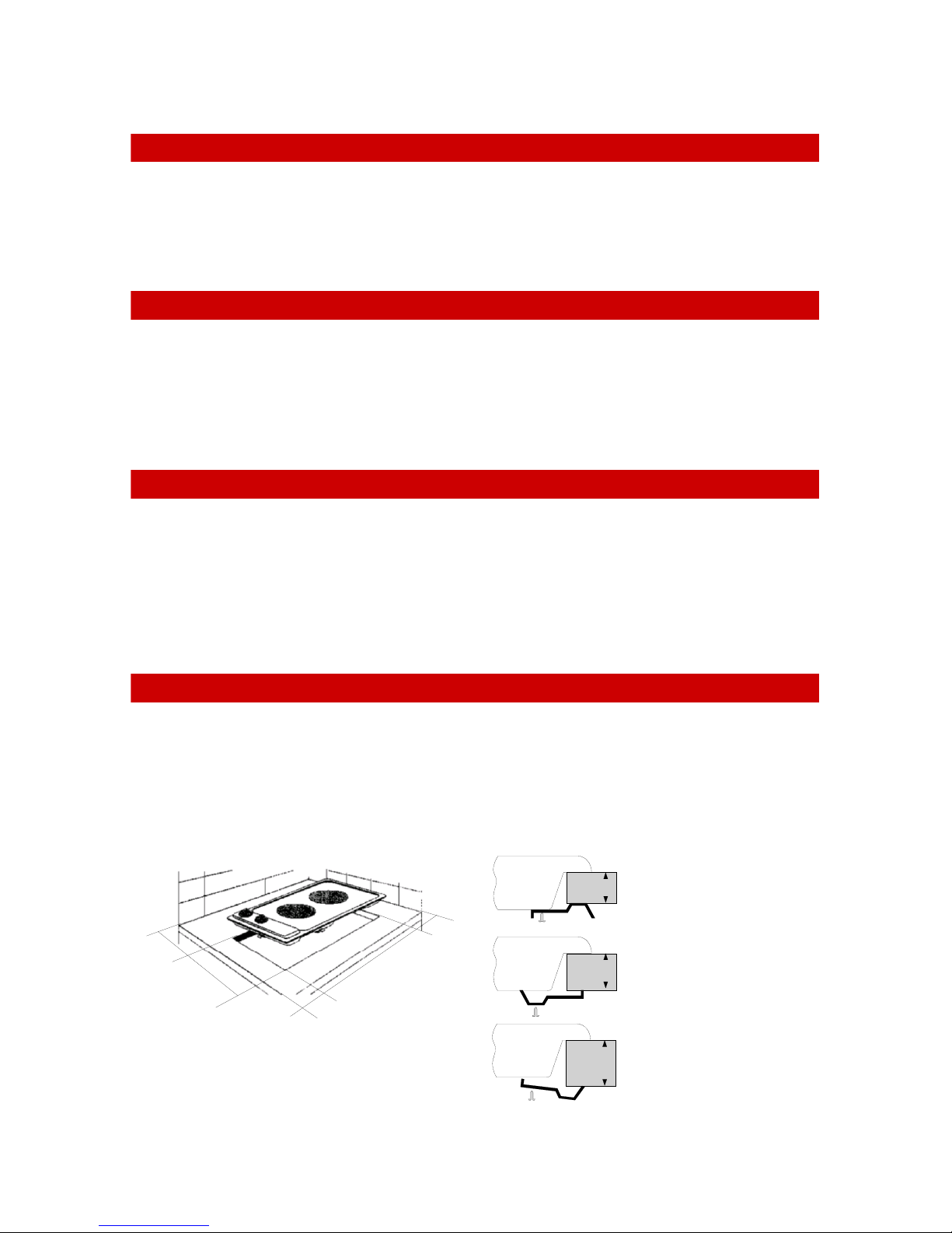
INSTALLATION
• The hob should be installed in a ventilated cupboard fitted with a sturdy worktop and
must be secured using the fixing brackets provided. See sketch for details on aperture
size and fixing method.
• Remove the sealing gasket from the packaging and secure the gasket to the underside
of the hob frame.
Fixing method
2030
for countertops
between
20mm and 40 mm
thick.
For 40mm thick countertops, use the second
40
set of fixing holes.
1
0
(
m
0
i
n
)
2
6
8
0
5
Aperture (268 mm x 490 mm )
for the Domino range of hobs.
Gas, Solid plate and Ceran.
)
0
n
6
i
m
(
0
9
4
VENTILATION
Room ventilation is vital for the efficient performance of the appliance and
for the safety of the occupants in the room in which the appliance is
installed.
ELECTRICAL INSTALLATION
“This appliance must be earthed. The manufacturer and the seller do not
accept responsibility for any damage due to incorrect installation or
electrical connection.”
• The Solid plate, Ceran and Gas hobs are fitted with a 15 Amp 3 pin plug.( The Gas
hob requires an electrical connection for the flame ignition system)
• Insert the plug into an earthed 15 Amp wall socket.
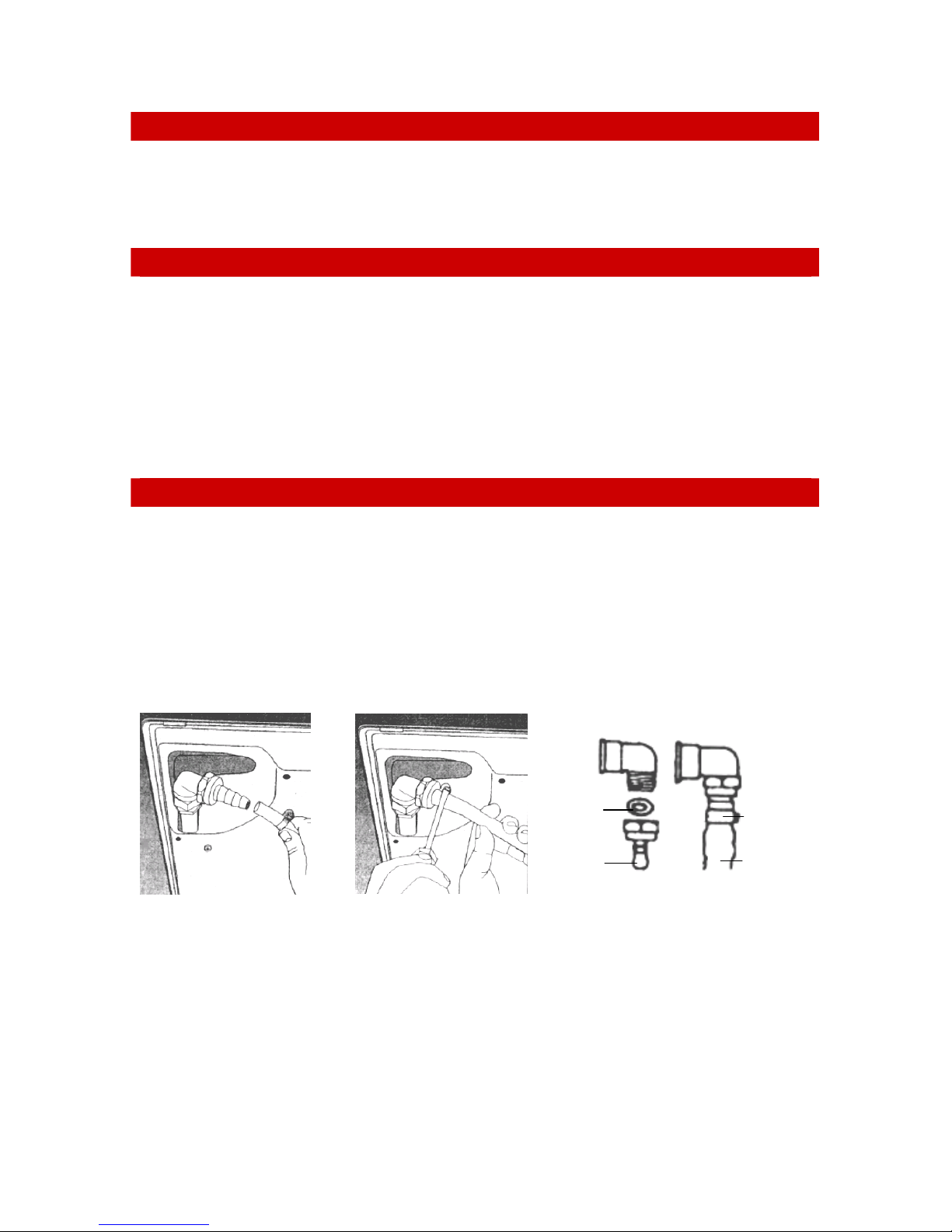
LPG GAS INSTALLATION
“This appliance uses LPG (bottle) gas. The manufacturer and the seller do
not accept responsibility for any damage due to incorrect installation or
gas connection.”
• Soak the end of the plastic hose in hot water to soften it and then push the hose end
fully over the hose nozzle. (see sketch 1 below)
• Secure the hose by tightening the hose clamp. (See sketch 2 below)
• In a similar fashion, secure the other end of the hose to the regulator on the gas bottle.
1 2
O Seal
Nozzle Hose
Clamp

Caution: Never use a naked flame to check for gas leaks
• Check for gas leaks after installation and whenever a new or re-filled gas bottle is
used for the first time.
• Ensure that the control knobs on the hob are in the OFF position.
• Open the valve on the Gas bottle.
• Using a small paintbrush, apply some soapy water to all the connections.
• If there is a leak, bubbles will appear.
• If this happens, close the valve on the gas bottle.
• Check and tighten the connections immediately.
• Repeat the procedure to ensure that there are no further leaks.
THE CONTROL PANEL SYMBOLS
REAR
PLATE
FRONT
PLATE
LPG GAS HOB
Operating the gas burners
• To switch the burner on, push down slightly on the relevant control knob and then
turn it to the left (counter – clockwise)
• The large flame symbol on the knob indicates the maximum and the small flame the
lowest setting.
Ignition button
• Push and hold the button down immediately after the control knob has been set to the
desired position.
• The gas will then be lit automatically.
• Release the button 3 to 5 seconds after the flame is observed at the burner.
• If the flame fails to continue burning, please repeat the sequence.
• The button will ignite either of the burners.
Flame failure –safety cut out.
• Should the flame extinguish for whatever reason, the flow of gas to the burner will
automatically be terminated.
Action to be taken in the event of a burn back
• In the event of a burn back (where the flame burns back into the jet) immediately turn
off the control to the affected burner.
• Wait a few minutes and relight the burner in the normal manner.
• If the burn back occurs again, turn off the control knob to the affected burner, and
consult the nearest Defy service technician, who will advise you.
 Loading...