

Page 1
Definitive Technology
DI LCR
OWNER’S MANUAL
5.5LCR
Specifications
5.5LCR
Woofer
Tweeter
15-5/16" (38.9cm)
7-3/8" (18.7cm)
14-3/8" (36.4cm)
6-7/16" (16.4cm)
3-5/8" (9.3cm)
3-1/8" (7.27cm)
2@5-1/4" (13.3cm)
1@1"(25mm)
8 lbs (3.6Kg)
28Hz - 30kHz
89dB
4-8 Ohms
10 -250 WPC
Grille Length
Grille Width
Cutout Width
Cutout Length
Total Depth *
Mounting Depth In-Wall **
Product Weight
Frequency Response
Sensitivity
Impedance
Recommended Amp Power
* From back of mounting flange to deepest part of product
** Total depth when product installed in 1/2" (12.7 mm) thick material
6.5LCR
17-1/8" (43.5cm)
8-5/16" (21.0cm)
16-3/16" (41.0cm)
7-5/16" (18.6cm)
3-5/8" (9.3cm)
3-1/8" (7.27cm)
2@6-1/2" (16.5cm)
1@1"(25mm)
8.5 lbs (3.9Kg)
26Hz - 30kHz
90dB
4-8 Ohms
10 - 275 WPC
6.5
LCR
Thank You
Thank you for choosing Definitive Technology Disappearing In-Wall Loudspeakers.
The DI Series products offer extraordinary sound quality from speakers that are
barely visible when installed in a wall or ceiling. Our engineers spent many
years developing this product. In order to ensure that you experience the finest
performance possible, we encourage you to take a moment to fully read this
owner’s manual and familiarize yourself with the proper installation and set-up
procedures for your DI Series speaker.
Unpacking Your Disappearing In-Wall Speakers
Please Inspect For Shipping Damage
Each loudspeaker leaves our plant in perfect condition. Any visible or concealed
damage most likely occurred in handling after it left our plant and should be reported
at once to your Definitive dealer or the delivery company that delivered your loud-
speaker. Please unpack your system carefully. Save all cartons and packing materials
in case you move or need to ship your system. Record the serial number found on
the back of the speakers and on the carton in this manual and save it for future
reference should your speaker need service. For your best protection, register your DI
Series products on-line at http://www.definitivetech.com/Registration/.
Page 2
Definitive Technology
1
– 12 inches
(2.5 – 31cm)
1 – 3 inches
(
25 – 75mm)
Painting DI LCR Speakers
Your DI Series speakers may be painted to match the color of the wall
or ceiling in which they are installed. Failure to follow the following
painting instructions may result in seriously degraded sound quality.
It is your responsibility to make sure your painting contractor sees and
follows these instructions.
1. DO NOT PAINT THE GRILLE WITH A BRUSH OR ROLLER —
they will clog the fine mesh of the grille and cloth scrim and result
in poor sound quality.
2.
Remove the grille from the speaker and place it on a drop cloth,
newspaper or plastic sheet.
3. The grille MUST be spray painted with one of the following:
• Spray paint that closely matches the desired finish/color
• A custom spray bomb color matched to your paint finish
• Indoor latex paint using a spray gun (paint must be diluted
to the paint manufacturer’s specifications)
4. Do not remove the backing cloth (scrim).
5. Paint should be applied in a series of thin coats sprayed at
approximately 60 degrees from the grille surface, allowing each
coat to fully cure before applying additional coats.
6. To ensure that the paint distribution is evenly applied, each coat
should be applied from at least 4 different directions to the grille.
(N, S, E & W) This will ensure an even coverage on the grille.
7. Once the grille has been painted and the paint has fully cured, you
may use a brush or small roller to touch-up the outer edge of the
grille frame — being VERY careful not to get any additional paint
on the grille mesh surface.
Figure 1
TV
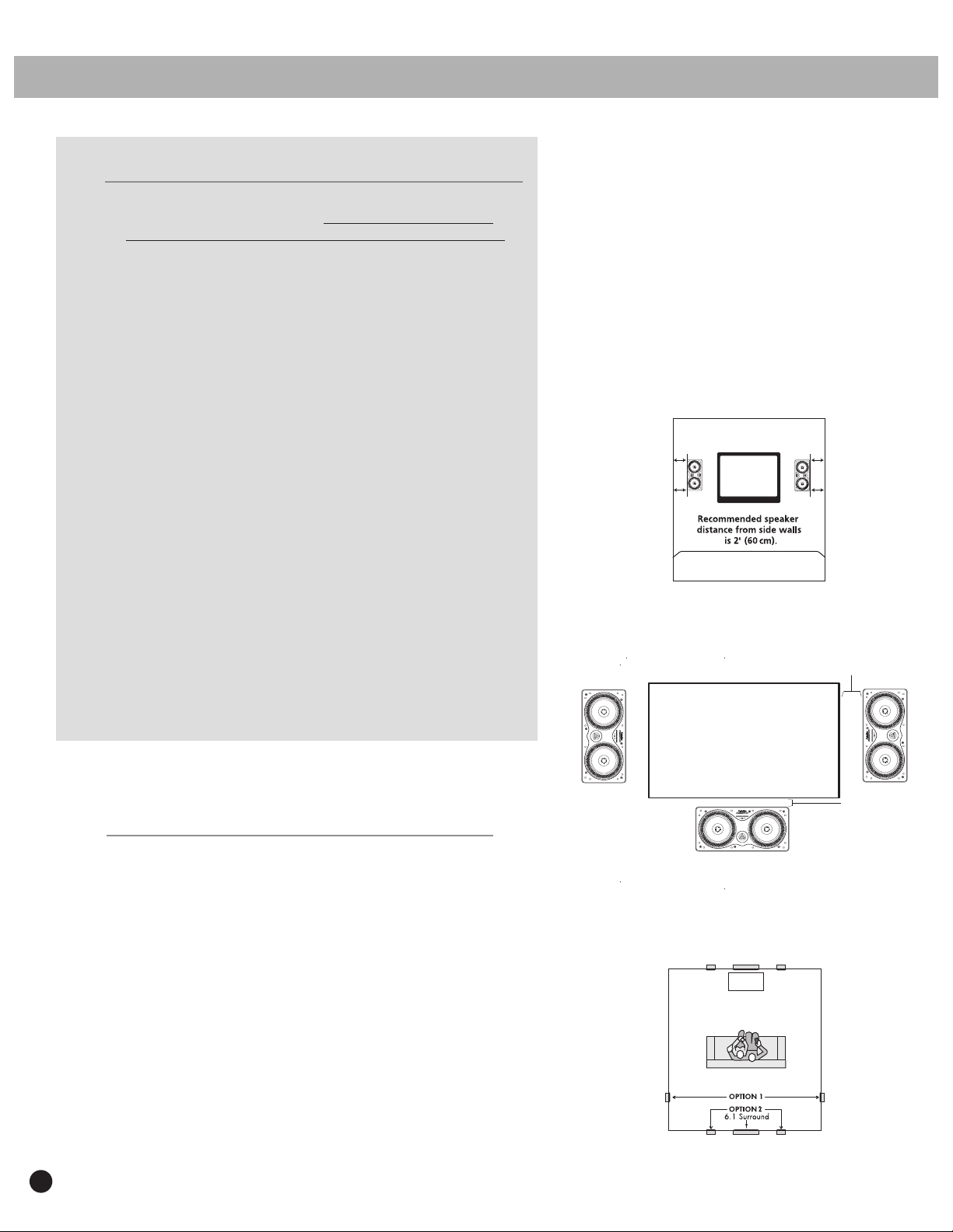
Placement Options
Definitive Technology DI Series Loudspeakers give you nearly endless
placement options. But remember that placement choice for your in-wall
speakers bears careful consideration, as installation requires that you cut a
hole in your wall or ceiling. It is best to keep the speakers at least 2 feet
(60 cm) from side walls [Figure 1]. When using DI Series models in home
theater applications follow the guidelines illustrated in Figures 2 and 3.
Orient the left and right speakers so that the tweeters are on the outside
edge as shown in Figure 2. Definitive DI Series In-Wall Loudspeakers have
aimable tweeters that allow you to focus their sound toward or away from
your listening area depending on the application (see page 6).
2
Figure 2
Figure 3
Page 3
Installation
Installation Cautions
Installation of Disappearing Series Loudspeakers requires skills in using
tools such as a drill, screwdriver, saws and power tools. Installation also
entails running wires through walls. You should have a thorough under-
standing of local building and fire codes and a familiarity with the area
behind the wall or ceiling into which you plan to install your speakers.
When cutting holes in and running wires through walls/ceilings, you
run the risk of cutting electrical wires or water pipes, thereby causing
safety hazards and property damage. If you are in any doubt that you
possess the necessary skills or tools, contact your Definitive Technology
dealer, general contractor or a professional installer.
Required Tools
• Pencil for marking the location of installation.
• Bubble level
• Keyhole saw, utility knife or material- appropriate incising implement
for cutting drywall or other wall material.
• Phillips head screwdriver.
• Power drill with appropriate bit (optional, for starting wall cut).
DI LCR
Template
OWNER’S MANUAL
Figure 4
Installation Procedure
You must first install speaker wires that meet appropriate building and fire
codes before installing the speakers. Use at least 18 gauge wire or heavier to
ensure optimum sound quality.
• Make sure the material into which you plan to mount the speakers
(plaster, drywall, paneling, stone, etc.) can support the weight of the
speakers (see specification page for the weight of your model).
• Make sure the locations you select do not conceal studs, electrical wiring
or plumbing. Prior to installation, hold the speaker with grille on in your
chosen location to make sure it safely clears obstacles such as studs,
corners, beams, lighting fixtures and door/window frames. Your cutout
must be at least 2" (50 mm) from adjoining walls or ceiling, internal studs
or plumbing.
• NOTE: The DI 5.5
only if it is perfectly centered between the studs. Plan the placement of
your on-wall TV and speakers very carefully before cutting holes. The DI
6.5LCR will not fit between standard-spaced wall studs when used in a
horizontal orientation. If you wish to use a DI 6.5LCR as a horizontal center
channel speaker or if you cannot center a DI 5.5LCR between studs, consult
a professional installer.
LCR will fit between studs when used horizontally but
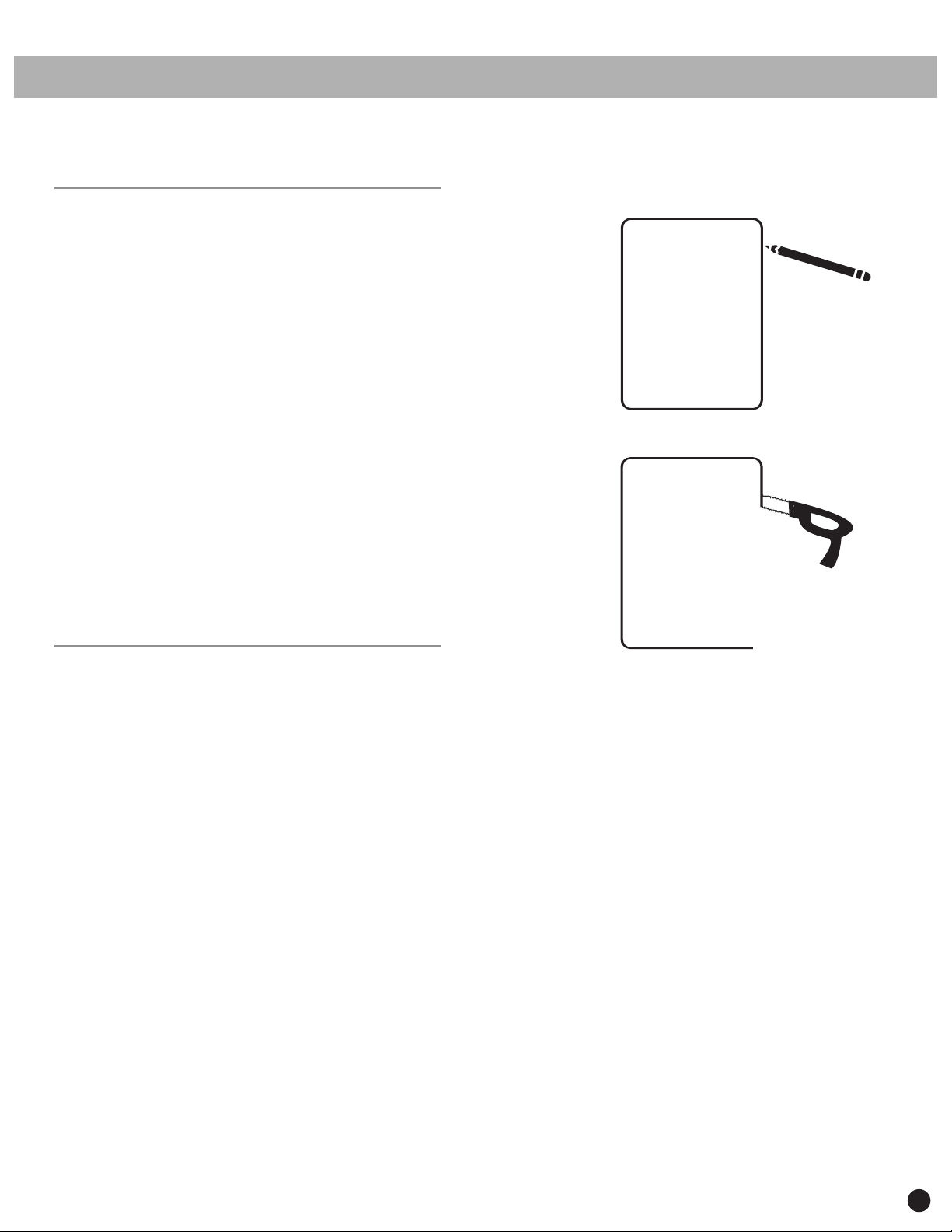
Figure 5
• Using the supplied template, trace the installation location with a
pencil. You can do this by holding the template in your preferred
location and tracing around it. Use a bubble level to square and level
the template [Figure 4].
• Carefully cut the hole with the appropriate cutting tool for your wall
or ceiling material. Start the hole by drilling a hole on the inside of the
tracing (with the drill bit just inside the line). Use this hole to insert the
saw or knife and begin cutting [Figure 5].
• Once you have cut the hole, pull the speaker wire out of the hole and
connect the speaker. Strip 1/2" inch (12 mm) of insulation from each of
the two conductors of the wire to expose the bare metal and twist each
of the conductors into a single unfrayed strand. Note that one of the
terminals on the rear of each speaker is marked red (+) and the other
black (-). Make certain that you connect the wire from the red terminal
(+) of your amplifier or receiver to the red terminal (+) on your speaker
and the wire from the black terminal (-) of your amplifier or receiver to
the black terminal (-) on your speaker. Most wire has some indicator
(such as color-coding, ribbing or writing) on one of the two conductors
to help you maintain consistency [Figure 6].
3
Page 4

DI LCR
AMPLIFI ER OR
R
ECEIVER
OWNER’S MANUAL
Installation Continued
• Push down on the top of the terminal to reveal the wire
hole in the side of the terminal post and insert the wire into
the hole [Figure 7]. Release the pressure on the terminal to
secure the wire.
• Loosen the rotating lock arms by turning the lock arm
screws on the front of the speaker counter clockwise 1⁄2 to 1
turn, just enough to allow the lock arm to move freely.
[Figure 8]. Make sure that the rotating lock arms are flipped
inwards [Figure 9] so that the speaker fits into the cutout.
• Place the speaker carefully into the cutout. If you have a
bubble level, use it to help you correctly align the speaker.
Tighten the lock arm screws with a screwdriver [Figure 10].
This will rotate the lock arms [Figure 11] and secure the
speaker to the wall/ceiling. Do not over-tighten the lock
arm screws. If you are using a powered screwdriver or drill
set the torque to a value of 7 in. – lb. (8dN – m).
• Install the grille on the speaker frame. Powerful magnets
hold the grille in place.
Figure 6
SAFETY FIRST
When installing your DI Series Loudspeakers, be
aware of the weight of your particular model (see
specification page for the weight of your model) and
the sturdiness of the material into which you are
installing the speaker. Also be aware of any
concealed studs, electrical wiring or plumbing in the
wall or ceiling into which you are installing the
speakers. If you are not sure of a safe way to install
these speakers, consult a professional installer, your
authorized Definitive Technology dealer, or a building
contractor.
Figure 7
4
Page 5

Definitive Technology
Lock arm
screws.
Turn counter
clockwise
to loosen.
Lock arm
screws.
Turn clock-
wise to
tighten lock
arms and
secure speaker
to surface.
Figure 8
Lock arms
tucked
in prior
to installing
speaker
in wall.
Figure 9
Figure 10
Figure 11
5
Page 6

Definitive Technology
Figure 12a
Push gently
to set angle.
Environmental EQ
If your listening room has smooth sheetrock walls, hardwood floors,
and non-cushioned furniture, the sound will be overly “bright” and
unnatural. Engaging the Environmental EQ feature [figure 13] (by
selecting the “–” setting) compensates for the effect of overly loud tre-
ble. If your room is has a lot of absorbing surfaces such as over-stuffed
furniture, heavy drapes and rugs such that the speakers sound “dull,”
engage the “+” setting to boost treble response. Leave the switch in the
center position in rooms with a balance of reflecting and absorbing sur-
faces (most rooms fall into this category).
Figure 12b
Aiming the Tweeter
To aim the tweeter, first install the speaker in the desired location.
Gently push the tweeter in the direction you wish to point it
[figure 12a & 12b]. For rear/surround speakers, aim the tweeter
toward the nearest reflecting surface (an adjacent wall or
ceiling) for a more diffuse sound field (if you want a more
direct sound, aim the tweeters at your listening position).
Figure 13
6
Page 7

NOTES
DI LCR
OWNER’S MANUAL
Technical Assistance
It is our pleasure to offer assistance if you have any questions regarding
your Definitive loudspeakers. Please contact your nearest Definitive
Technology dealer or call us directly at (800) 228-7148 (US & Canada) or
01 (410) 363-7148 (all other countries), or e-mail us at
info@definitivetech.com.
Service
Service work on your Definitive loudspeakers will normally be
performed by your local Definitive Technology dealer. If your dealer is
unable or unwilling to perform service, contact us for alternative
options. Please note that the address given in this manual is the address
of our offices only. Under no circumstances should loudspeakers
be shipped to our offices or returned without contacting us
first and obtaining return authorization.
Definitive Technology Offices
11433 Cronridge Drive
Owings Mills, Maryland 21117
Phone: (800) 228-7148 (US & Canada)
01 (410) 363-7148 (all other countries)
5.5BPS
WARNING: LISTEN CAREFULLY
Definitive Technology loudspeakers and subwoofers are capable of
playing at extremely high volume levels, which could cause serious or
permanent hearing damage. Definitive Technology accepts no liability
for hearing loss, bodily injury or property damage resulting from the
misuse of its products.
You should limit prolonged exposure to volumes that exceed
85 decibels (dB).
For more about safe volume levels, refer to the Occupational
Health and Safety Administration (OSHA) guidelines at:
www.osha.gov/dts/osta/otm/noise/standards_more.html.
The DI 5.5BPS is
the perfect surround
speaker to use with DI
LCR models in home
theater systems.
7
Page 8

DI LCR
OWNER’S MANUAL
LIMITED USA WARRANTY
5-YEARS FOR DRIVERS AND CABINETS, 3-YEARS FOR ELECTRONIC COMPONENTS
DEI Sales Co., dba Definitive Technology (herein “Definitive”) warrants to the original
retail purchaser only that this Definitive loudspeaker product (the “Product”) will be free
from defects in material and workmanship for a period of five (5) years covering the
drivers and cabinets, and three (3) years for the electronic components from the date of
the original purchase from a Definitive Authorized Dealer. If the Product is defective in
material or workmanship, Definitive or its Authorized Dealer will, at its option, repair
or replace the warranted product at no additional charge, except as set forth below. All
replaced parts and Product(s) become the property of Definitive. Product that is repaired
or replaced under this warranty will be returned to you, within a reasonable time, freight
collect. This warranty is non-transferrable and is automatically void if the original
purchaser sells or otherwise transfers the Product to any other party.
This Warranty does not include service or parts to repair damage caused by accident,
misuse, abuse, negligence, inadequate packing or shipping procedures, commercial use,
voltage in excess of the rated maximum of the unit, cosmetic appearance of cabinetry not
directly attributable to defects in material or workmanship. This warranty does not cover
the elimination of externally generated static or noise, or the correction of antenna
problems or weak reception. This warranty does not cover labor costs or damage to the
Product caused by installation or removal of the Product. Definitive Technology makes no
warranty with respect to its products purchased from dealers or outlets other than
Definitive Technology Authorized Dealer.
THE WARRANTY IS AUTOMATICALLY VOID IF:
1) The product has been damaged, altered in any way, mishandled during transportation,
or tampered with.
2) The product is damaged due to accident, fire, flood, unreasonable use, misuse, abuse,
customer applied cleaners, failure to observe manufacturers warnings, neglect or
related events.
3) Repair or modification of the Product has not been made or authorized by Definitive
Technology.
4) The product has been improperly installed or used.
This product complies with the essential requirements of the EMC directive 89/336/EEC.
Product must be returned (insured and prepaid), together with the original dated proof of
purchase to the
nearest Definitive factory service center. Product must be shipped in the original shipping
container or its equivalent. Definitive is not responsible or liable for loss or damage to
Product in transit.
THIS LIMITED WARRANTY IS THE ONLY EXPRESS WARRANTY THAT
APPLIES TO YOUR PRODUCT. DEFINITIVE NEITHER ASSUMES NOR
AUTHORIZES ANY PERSON OR ENTITY TO ASSUME FOR IT ANY OTHER
OBLIGATION OR LIABILITY IN CONNECTION WITH YOUR PRODUCT OR THIS
WARRANTY. ALL OTHER WARRANTIES, INCLUDING BUT NOT LIMITED TO
EXPRESS, IMPLIED,WARRANTY OF MERCHANTABILITY OR FITNESS FOR A
PARTICULAR PURPOSE, ARE EXPRESSLY EXCLUDED AND DISCLAIMED TO
THE MAXIMUM EXTENT ALLOWED BY LAW. ALL IMPLIED WARRANTIES ON
PRODUCT ARE LIMITED TO THE DURATION OF THIS EXPRESSED
WARRANTY. DEFINITIVE HAS NO LIABILITY FOR ACTS OF THIRD PARTIES.
DEFINITIVE’S LIABILITY, WHETHER BASED ON CONTRACT, TORT, STRICT
LIABILITY, OR ANY OTHER THEORY, SHALL NOT EXCEED THE PURCHASE
PRICE OF THE PRODUCT FOR WHICH A CLAIM HAS BEEN MADE. UNDER NO
CIRCUMSTANCE WILL DEFINITIVE BEAR ANY LIABILITY FOR INCIDENTAL,
CONSEQUENTIAL OR SPECIAL DAMAGES. THE CONSUMER AGREES AND
CONSENTS THAT ALL DISPUTES BETWEEN THE CONSUMER AND
DEFINITIVE SHALL BE RESOLVED IN ACCORDANCE WITH CALIFORNIA
LAWS IN SAN DIEGO COUNTY, CALIFORNIA. DEFINITIVE RESERVES THE
RIGHT TO MODIFY THIS WARRANTY STATEMENT AT ANY TIME.
Some states do not allow the exclusion or limitation of consequential or incidental
damages, or implied warranties, so the above limitations may not apply to you. This
warranty gives you specific legal rights, and you may also have other rights which vary
from state to state.
Authorized Dealer from whom the Product was purchased, or to the
©2009 DEI Sales Co. All rights reser ved.
Other Disappearing In-Wall Series Speakers
DI 3.5R
DI 6.5STR DI 8R
DI 4.5R DI 5.5R
DI 5.5S
DI 6.5R
DI 6.5S
FAAT090309
8
For more information on Definitive Technology Loudspeakers and accessories,
visit www.definitivetech.com, or email info@definitivetech.com.
Definitive Technology, Owings Mills, Maryland, USA. 800-228-7148
 Loading...