

DeFelsko PosiTector UTG, PosiTector UTGC, PosiTector UTG-STD, PosiTector UTG-ME, PosiTector UTG-CA Calibration Procedure
...Page 1

Management Procedure 2585
Revision: F
Date Issued: Feb 21, 2003
Date Revised: June 10, 2019
Calibration Procedure
DeFelsko Corporation
PosiTector UTG, UTG-STD, UTG-ME, UTG-
C, UTG-CA, UTG-CLF, UTG-CX, UTG-M &
UTG-P
Ultrasonic Thickness Gage
Table of Contents
1 Introduction and UUC Performance Requirements ............................................................................................ 2
Table 1-1 Measurement Ranges ......................................................................................................................... 2
2 Measurement Standards and Support Equipment Performance Requirements .................................................. 2
Table 2-1 UUC Accuracy Requirements and Description ................................................................................. 2
Table 2-2 Minimum Use Specification .............................................................................................................. 3
Table 2-3 Actual Equipment Specification ........................................................................................................ 3
Table 2-4 Calibration Environmental and Warm Up Requirements .................................................................. 3
3 Preliminary Operations ....................................................................................................................................... 3
4 Calibration Process ............................................................................................................................................. 4
5 Performance Requirements ................................................................................................................................ 5
Table 5-1 Performance Requirements and Calibration Data for PosiTector UTG ............................................. 5
Management Procedure Change Notice ........................................................................................................................ 6
Management Procedure 2585 Rev. F
1
Page 2
1 Introduction and UUC Performance Requirements
1.1 This procedure describes the calibration of the PosiTector UTG Ultrasonic Thickness
Gage and probe.
Table 1-1 Measurement Ranges
Models Measurement Range * Velocity Range
UTG, UTG-STD, UTG-C
UTG-CA, UTG-CLF, UTG-CX
UTG-M & UTG-ME
UTG-P
* The actual measurement range of the system depends on the material being measured.
Ranges shown are based on carbon steel.
The unit being calibrated will be referred to as the UUC (unit-under-calibration).
2 Measurement Standards and Support Equipment Performance Requirements
2.1 The UUC accuracy requirements are based upon the published UUC performance
specifications.
2.2 Minimum-Use-Specifications are the minimum test equipment specifications required to
meet all the UUC accuracy requirements and the test uncertainty ratio applied.
2.3 The uncertainty ratio applied in this Calibration Procedure is 4:1 unless otherwise stated.
The UTG-P has an uncertainty ratio of 2:1.
Table 2-1 UUC Accuracy Requirements and Description
Model Range
UTG, UTG-STD, UTG-C
UTG-CA, UTG-CLF, UTG-CX
(0.040 - 5.000”)
1.0 - 125 mm
(0.040 - 5.000”)
2.5 - 125 mm
(0.100 - 5.000”)
0.200 – 12.000 mm
(0.008 – 0.472”)
1.0 - 125 mm
1,250 to 10,000 m/s
(0.0492 to 0.3930 in/µs)
Performance
Specifications Test Method
± 0.03 mm
(± 0.001”)
Compare to
Step Blocks
UTG-M & UTG-ME
UTG-P
Management Procedure 2585 Rev. F
2.5 - 125 mm
(0.100 - 5.000”)
0.200 – 12.000 mm
(0.008 – 0.472”)
± 0.03 mm
(± 0.001”)
± 0.010 mm
(± 0.0004”)
Compare to
Step Blocks
Compare to
Step Blocks
2
Page 3

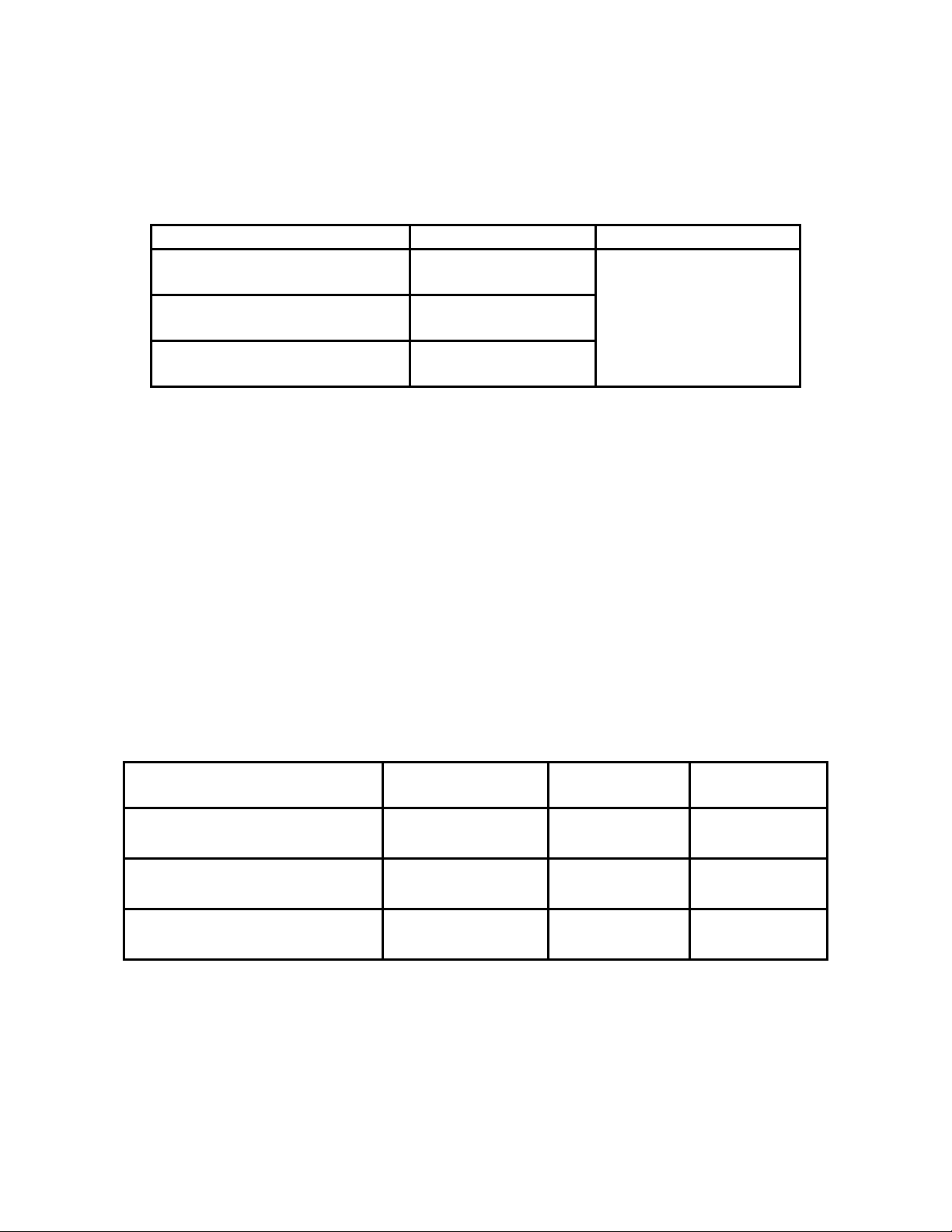
Table 2-2 Minimum Use Specification
Model Range Accuracy
UTG, UTG-STD, UTG-C
UTG-CA, UTG-CLF, UTG-CX
UTG-M & UTG-ME
UTG-P
Table 2-3 Actual Equipment Specification
UUC Model Equipment
Generic Name
UTG, UTG-STD, UTG-C
UTG-CA, UTG-CLF,
UTG-CX, UTG-M &
UTG-ME
UTG-P Step Blocks
Caution: The instructions in this Calibration Procedure relate specifically to the equipment and
conditions listed in this section. If other equipment is substituted, the information and
instructions must be interpreted accordingly.
Table 2-4 Calibration Environmental and Warm Up Requirements
Measurement Standards & Support Equipment
Environmental Requirements:
Measurement Standards & Support Equipment
Warm-up and Stabilization Requirements:
Step Blocks
Actual Equipment Specifications Manufacturer &
2.50 - 12.50 mm
(0.100 - 0.500”)
(0.020 – 0.098”)
1.0 - 125 mm
(0.040 - 5.000”)
2.5 - 125 mm
(0.100 - 5.000”)
0.200 – 12.000 mm
(0.008 – 0.472”)
Range Accuracy
± 0.005 mm
(± 0.00020”)
0.50 - 2.50 mm
Temperature: 23 ± 5° C.
Relative Humidity: Less than 95%
None
± 0.005 mm
(± 0.00020”)
± 0.008 mm
(± 0.00025”)
± 0.008 mm
(± 0.00025”)
± 0.003 mm
(± 0.0001”)
Model Applicable
PH Tool Custom
5 Step Block
PH Tool Custom
5 Step Block
3 Preliminary Operations
Note: Review the entire document before starting the calibration process.
3.1 Visual Inspection
3.1.1 Visually inspect the UUC for:
• Probe tip wear or damage
• Other damage or wear
• Proper identification
3.1.2 Damage or excess wear shall be repaired prior to beginning the calibration process.
3.2 Gage Reset
Management Procedure 2585 Rev. F
3
Page 4

Note: Please refer to UUC instruction manual for menu navigation instructions, details
on features and operating instructions (i.e. required amount of couplant and pressure).
3.2.1 For bodies with serial number after 700,000; when the unit is powered down,
simultaneously hold the “+” and middle buttons until the rest symbol appears. All other
bodies press and hold the “+”.
3.2.2 All probes except UTG-P: After reset, select the Main Menu “Cal Settings” function and
then “Zero”. Follow the on screen prompt to measure the zero plate provided with the
probe. After zeroing, verify the probe on the thinnest and thickest steps of the 5-step
block. Allowable tolerances following zeroing are ± 0.05 mm (0.002”).
3.2.3 UTG-P probes: Verify the probe face is clean. After reset, select the Main Menu “Cal
Settings” function and then “Zero”. Hold the probe in air and follow the on screen
prompt. After zeroing, verify the probe on the thinnest and thickest steps of the
appropriate 5-step block. Allowable tolerances following zeroing are ± 0.05 mm
(0.002”).
4 Calibration Process
Note: Whenever the test requirement is not met, verify the results of each test and take
corrective action before proceeding.
4.1 Review the Performance Requirements Table 5-1.
4.2 Select the 2-Pt Adjust feature from the Cal Settings section of the menu. Perform a two-
point calibration using the thinnest and thickest of the steps on the appropriate 5-step
block. This will adjust the sound velocity of the gage and the zero reference to the
material of the step block.
4.3 Using the appropriate Certificate of Calibration template for the UUC, record the
thickness from the Reference Standard label.
4.4 Determine the allowed range of readings using the calculation methods shown in column
A of table 5-1.
4.5 Use the UUC to take measurements on each step of the 5-step block. Verify that the
readings are within the allowable limits and record the readings on the Certificate of
Calibration.
Management Procedure 2585 Rev. F
4
Page 5

5 Performance Requirements
Note: The technician will collect the data needed to complete column B of Table 5-1. Do
not write in this procedure.
Table 5-1 Performance Requirements and Calibration Data for PosiTector UTG
Reference
Thickness
(mm)
A B
For imperial/metric readings convert using 1” = 25.4 mm
n For UTG-P: Calculation: A - 0.010 mm
For all other probes: Calculation: A - 0.03 mm
Y For UTG-P: Calculation: A + 0.010 mm
For all other probes: Calculation: A + 0.03 mm
Min. Reading
Allowedn
(mm)
Max. Reading
AllowedY
(mm)
Actual Gage
Measurement
(mm)
Management Procedure 2585 Rev. F
5
Page 6

Management Procedure Change Notice
Procedure Number: MP 2585
Revision Level: F
Date of Change: June 10 , 2019
Title: Calibration Procedure for PosiTector UTG, UTG STD,
UTG-C, UTG-CA, UTG-CLF, UTG-CX, UTG-M, UTGME & UTG-P
Reason for Change:
• New products
Description of Change:
• Updated Table 1-1
• Retitled and updated tables 2-1, 2-2 & 2-3
• Re-wrote section 2
• Re-wrote Sections 1.1 and 3.2.2.
• Added section 3.2.3
• Updated calculations in table 5
I confirm I have read and understand the procedure and the change described above.
Printed Name Signature Date
Management Procedure 2585 Rev. F
Management Form 0010.02-05/1998
6
 Loading...