

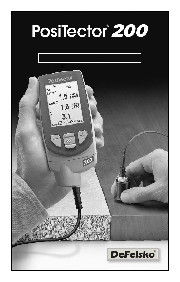
Quick Guide v. 3.0
Ultrasonic Coating Thickness Gage
Standard
and
Advanced
Introduction
Introduction
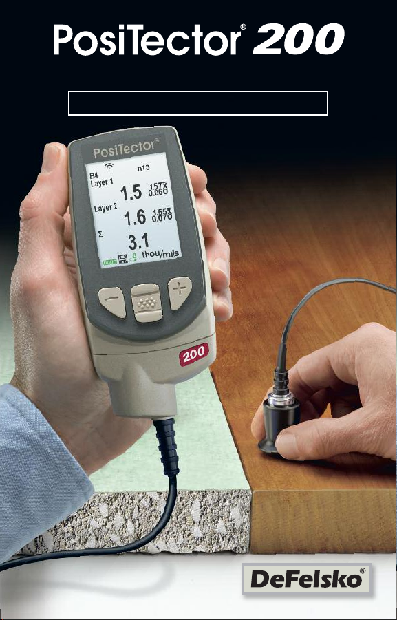
The PosiTector 200 is a hand-held Coating Thickness Gage that
uses a non-destructive ultrasonic principle to measure coating
thickness on a wide variety of substrates. It consists of a body
(Standard or Advanced) and a probe (see Probes pg. 2).
This Quick Guide summarizes the basic functions of the Gage.
Download the full instruction manual at:
www.defelsko.com/manuals
Quick Start
Quick Start
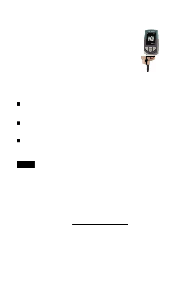
The PosiTector 200 powers-up when the center navigation button
is pressed. To preserve battery life, the instrument powers
down after approximately 5 minutes of no activity. All settings are
retained.
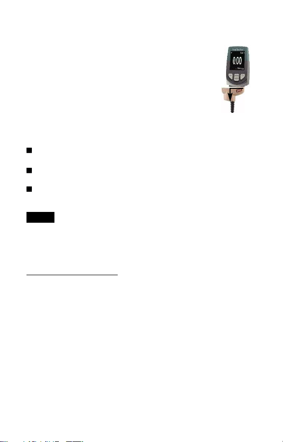
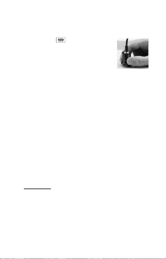
1. Remove the protective rubber cap from the probe.
2. Power-up Gage by pressing the center navigation button.
3. Zero the probe. (see pg. 5)
4. Adjust to a known thickness, if necessary. (see pg. 6)
5. Measure the part. (see pg. 3)
Menu Operation
Menu Operation
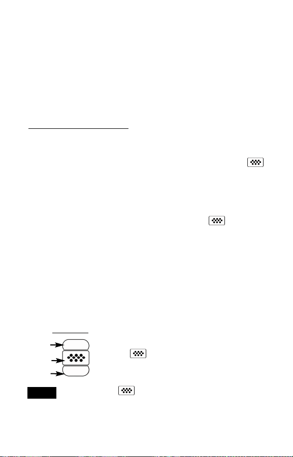
Gage functions are menu controlled. To access the Menu, powerup the gage, then press the center navigation button.
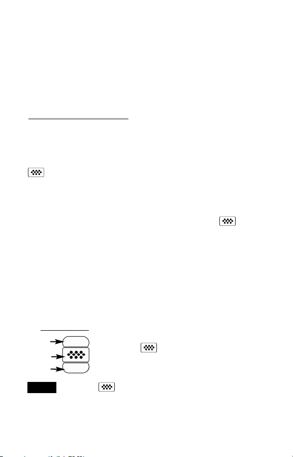
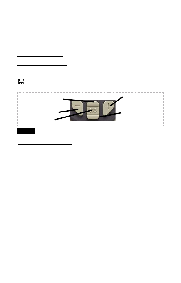
Navigation Button
Up
Center
Down
To navigate, use the Up and Down buttons to
scroll and to SELECT.
Select Exit to exit from any menu.
The center button is purposely recessed to help
NOTE:
eliminate unintentional powering-up of the gage.
1
Probes
Probes
T
o
d
i
s
c
o
n
n
e
c
t
a
p
r
o
b
e
f
r
o
m
a
b
o
d
y
,
p
o
w
e
r
-
d
o
w
n
t
h
i
n
s
t
r
u
m
e
n
t
a
n
d
s
l
i
d
e
t
h
e
p
l
a
s
t
i
c
p
r
o
b
e
h
o
r
i
z
o
n
t
a
l
l
y
(
i
n
t
h
e
d
i
r
e
c
t
i
o
n
o
f
t
h
e
a
r
b
o
d
y
.
R
e
v
e
r
s
e
t
h
e
s
e
s
t
e
p
s
t
W
h
e
n
p
o
w
e
r
e
d
-
u
p
,
t
h
e
d
e
t
e
r
m
i
n
e
s
w
h
i
c
h
s
e
l
f
-
c
h
e
c
k
.
PosiTector 200 probes are available for measuring a wide variety
of coating thickness applications.
B probe - 13 to 1000 microns (0.5 to 40 mils)
Ideal for polymer coatings on wood, plastic, composites, etc.
C probe - 50 to 3800 microns (2 to 150 mils)
Ideal for thicker coatings on concrete, fiberglass, etc.
D probe - 50 to 7600 microns (2 to 300 mils)
Ideal for thick, soft (attenuative) coatings such as polyurea
NOTE:
Range limits apply to polymer coatings only.
Additionally, the PosiTector accepts a number of probe types
including magnetic and eddy current coating thickness, surface
profile, environmental and ultrasonic wall thickness probes.
For the latest information on probe interchangeability, see
www.defelsko.com/probes
Couplant is required to propagate ultrasound into the coating.
Water is a good couplant for smooth coatings. Use the supplied
glycol gel for rougher coatings. While it is unlikely that the
couplant will damage the finish or leave a stain on the surface, we
suggest testing the surface by using the couplant on a sample. If
testing indicates that staining has occurred, a small amount of
water can be used instead of couplant. Consult the Material Safety
Data Sheet available on our website and your coating supplier if
you suspect the couplant may damage the coating. Other liquids
such as liquid soap may also be used.
p
r
o
b
e
Couplant
Couplant
P
r
o
a
t
t
a
c
h
o
s
i
T
e
c
i
s
a
t
t
a
c
c
o
w
)
a
w
a
a
t
h
y
n
e
w
p
r
o
r
a
u
t
o
e
d
a
n
d
e
o
n
n
e
c
t
o
r
f
r
o
m
t
h
e
o
b
e
.
m
a
t
i
c
a
l
l
y
d
o
e
s
a
2
PosiTector 200 - Theory of Operation
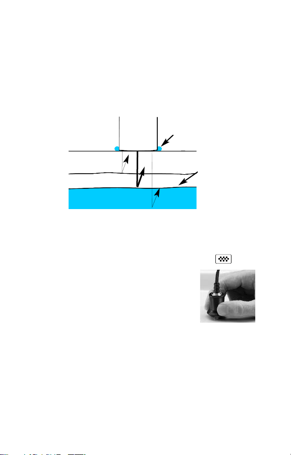
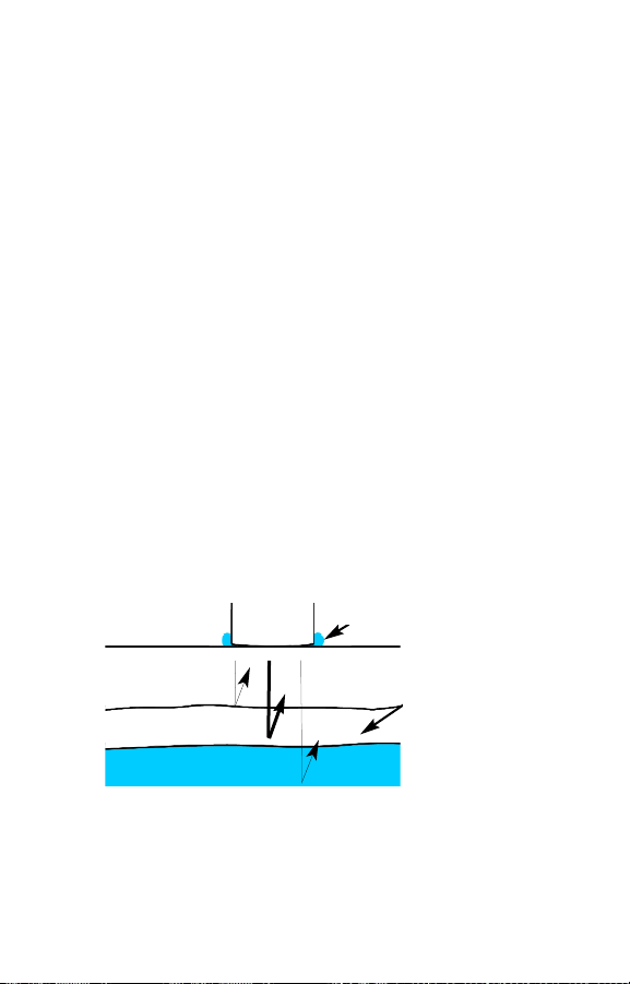
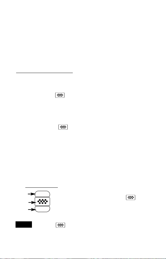
PosiTector 200 probes emit a high frequency sound pulse that
travels into the coating via a coupling gel and reflects from ANY
surface that is different in density. Coating thickness readings are
obtained by measuring the time taken for the ultrasonic signal to
propagate from the probe to the coating/substrate interface and
back. The travel time is divided by two and multiplied by the
velocity of sound for the coating to obtain the thickness of the
coating.
Probe
Coating 1
Coating 2
Substrate
How to Measure
How to Measure
1. Remove the protective rubber cap from probe.
2. Power-up Gage by pressing the center navigation button.
3. Apply couplant (see pg. 2) to the surface of
the part.
4. Place the probe FLAT on the surface and
press down.
5. Lift the probe when you hear a double BEEP,
- OR - leave probe on the surface in the same location for
continuous measurements.
6. When completely finished, wipe the probe clean of couplant
then return the Gage to the protective pouch. There is no need
to disconnect the probe from the PosiTector during storage.
Couplant
The PosiTector 200
interprets the largest
“echo” within the
selected range as
the coating/coating
or coating/substrate
echo.
3

Calibration, Verification and Adjustment
Calibration, Verification and Adjustment
Three steps ensure best accuracy…
1.Calibration - typically done by the manufacturer or a qualified
lab. All probes include a Certificate of Calibration.
2.Verification of Accuracy - as done by the user on known
reference standards such as the included plastic shims or
optional coating thickness standards.
3.Adjustment - to a known thickness.
Calibration
Calibration is the controlled and documented process of
measuring traceable calibration standards and verifying that the
results are within the stated accuracy of the Gage. Calibrations
are typically performed by the Gage manufacturer or by a certified
calibration laboratory in a controlled environment using a
documented process.
Verification
Verification is an accuracy check performed by the user using
known reference standards. A successful verification requires the
Gage to read within the combined accuracy of the Gage and the
reference standards.
Adjustment
Adjustment, or Calibration Adjustment is the act of aligning the
Gage's thickness readings to match that of a known reference
sample in order to improve accuracy of a gage on a specific
coating. See Thickness pg. 6
4
Cal Settings Menu
Cal Settings Menu
Zero
The probe must be periodically zeroed using the Zero menu option
to compensate for both extreme temperature and probe wear
effects. Before using, allow the probe to reach ambient
temperature. Wipe the probe clean of couplant. The icon
appears after probe is zeroed.
If measurements will be made in extreme hot or cold temperatures,
it is recommended to Zero the probe in the working environment.
If measurements will be made on rough substrates, it is
recommended to periodically Zero the probe to compensate for
wear.
Set Range
The measuring range of each probe can be changed depending on
the specific application or the expected thickness range of the
coating system.
For most applications, the default range values do not have to be
adjusted. But some conditions, like surface roughness, may cause
the Gage to display very low or non-repeatable readings. In this
case, the low range may be increased to cause the Gage to only
display readings above the Lo value set by the user.
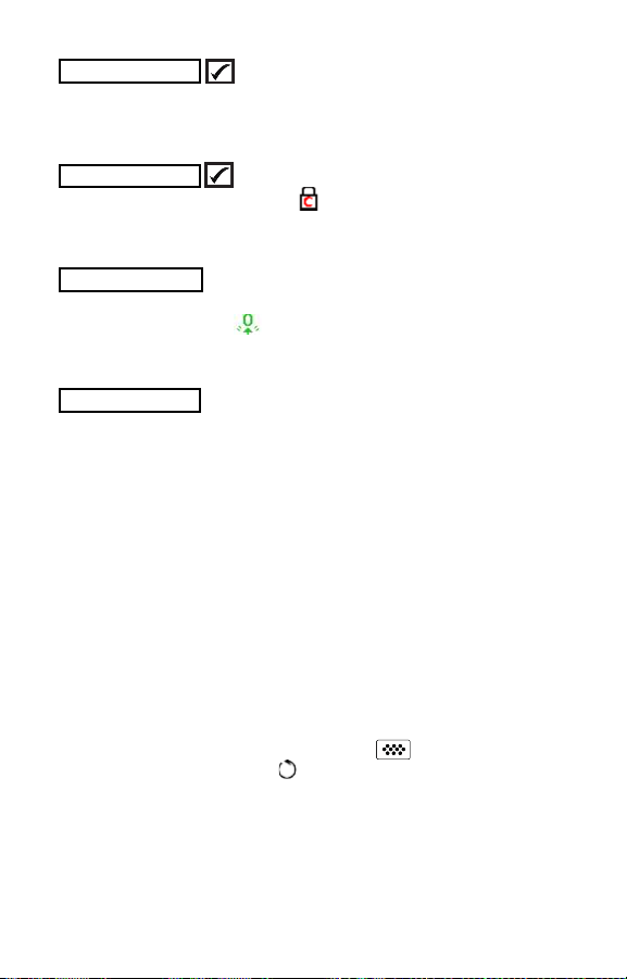
To adjust Set Range values...
1. Select or .
2. Use the (-)(+) buttons to decrease/increase the displayed value.
IMPORTANT:
The PosiTector 200 interprets the largest “echo” or “echoes”
within the selected range as the coating/coating or
coating/substrate echo. If the coating thickness is outside this
range, incorrect or dashed readings may occur.
5
Here are some typical Range settings...
Expected paint thickness Lo Hi
500µm (20 mils) on concrete 130µm (5 mils) 1000µm (40 mils)
50µm (2 mils) on wood 25µm (1 mil) 250µm (10 mils)
Thickness
The PosiTector 200 measures most polymer coatings accurately
out-of-box with no adjustment required.
To determine if an adjustment is necessary, select a coating
sample of known thickness as close as possible in composition to
the intended application. For best results, the thickness of the
sample should be equal to or slightly greater than the maximum
expected thickness of the coating to be measured.
Measure the coated sample. If the average of a series of
measurements on the sample is not close to the known
thickness...
1. Select the Thickness menu option.
2. Use (-) or (+) to decrease/increase the displayed measurement
thickness value to match the known thickness of the sample.
3. For Advanced models with multiple layers selected, use the
Down navigation button to select the next layer and adjust as
necessary.
4. To save adjustments, use Down navigation button to highlight
OK and press the center navigation button.
Polyurea
(PosiTector 200 D probes only)
When checked, the Gage loads a pre-programmed calibration
adjustment optimized for measurement of polyurea coatings.
Cal Lock
When checked, the icon appears and the current calibration
adjustment is “locked” to prevent further user adjustments.
Cal Reset
Restores the gage back to factory calibration and range settings.
The icon will appear on the display.
6
Setup Menu
Setup Menu
Reset
Reset (soft reset) restores factory settings and returns the Gage to
a known condition. The following occurs:
- All batches, stored measurements, images, batch names and
screen captures are erased.
- All calibration and range adjustments are cleared and returned
to the Gage’s factory settings.
- Menu settings are returned to the following:
Memory = OFF
Graphics = ON
Cal Lock = OFF
Bluetooth = OFF
Display = None
Layers = 1
Layer Name = Layer 1
Layer Color = blue
Perform a more thorough Hard Reset by powering down the
Gage, waiting several seconds, then simultaneously holding both
the center and (+) buttons until the Reset symbol
appears. This returns the instrument to a known, “out-of-the-box”
condition. It performs the same function as a menu Reset with the
addition of:
- Bluetooth Pairing info is cleared.
- Menu settings are returned to the following:
Units = microns
Flip Display = Normal
White on Black = OFF
Language = English
NOTE:
Date, Time and WiFi are not affected by either Reset.
Battery Type = Alkaline
Backlight = Normal
USB Drive= ON
Auto Sync = OFF
Battery Type
Selects the type of batteries used in the Gage from a choice of
“Alkaline”, “Lithium” or “NiMH” (Nickel-metal hydride
rechargeable). If NiMH is selected, the Gage will trickle charge the
batteries while connected via USB to a PC or optional AC charger.
The battery state indicator icon is calibrated for the selected
battery type. No damage will occur if the wrong battery type is
selected.
NOTE:
DeFelsko recommends the use of eneloop (NiMH)
rechargeable batteries.
7
Advanced models only)
Graphics
(
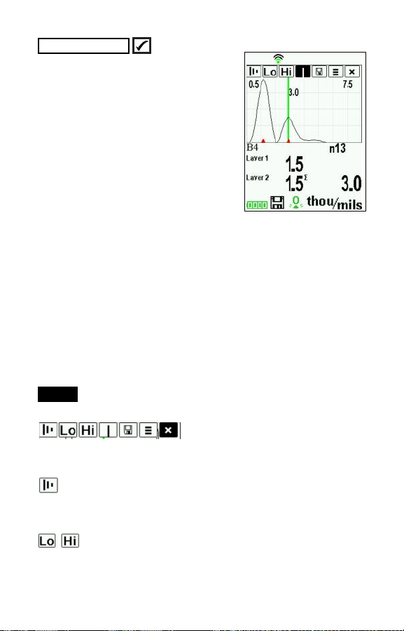
When selected, the Gage displays a
graphical representation of the ultrasonic pulse as it travels through the coating
system.
As the probe is depressed and the
ultrasonic pulse travels through the
coating system, the pulse encounters
changes in density at the interfaces
between coating layers and between the
coating and the substrate.
These interfaces are depicted by a "peak". The greater the change
in density, the higher the peak. The more gradual the change in
density, the greater the width of the peak. For example, two coating
layers made of essentially the same material and "blended" would
result in a low, wide peak. Two materials of very different density
and a well-defined interface would result in a high, narrow peak.
The PosiTector 200 chooses the highest peak (single layer) or
peaks (multi-layer) within the Set Range. For example, if the
number of layers is set to 3, the three highest peaks would be
identified with small red triangles. The peak values are also
displayed numerically as thickness measurements.
NOTE:
The Graphics display can also be accessed using the
Set Range menu option.
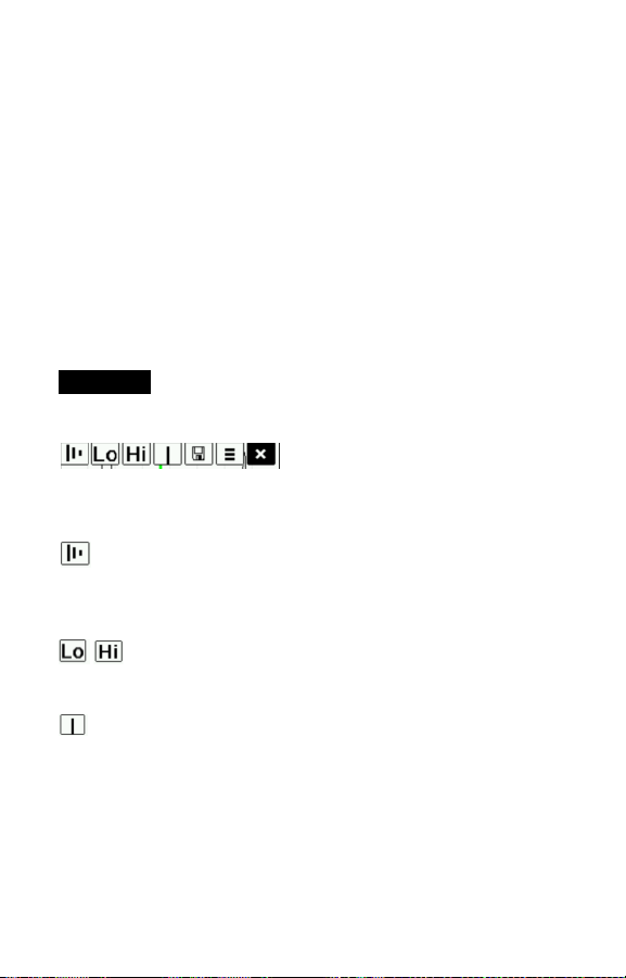
Use the navigation Up (move left) and Down (move right) buttons
to highlight icons on the graphic display.
Zoom - Visually magnifies the waveform of the displayed
peaks for more visibility. Pressing the (+) or (-) button repeatedly
will increase/decrease the zoom.
Set Range - Press the (-) or (+) buttons to adjust the
Gage’s Lo or Hi measuring range. (see pg. 5
)
8
Cursor - The Cursor allows for further analysis of displayed
waveform. Use the (-)(+) buttons to move the green cursor line left
or right over the waveform. The thickness value is displayed at the
top right of the cursor line. This feature is particularly
useful in multi-layer applications where there are more than
3 distinct layers.
Screen Capture - Press to capture and save an image
copy of the current display. The last 10 screen captures are stored
in memory and can be accessed when connected to a computer.
(see PosiSoft USB Drive pg. 10)
Shortcut:
capture any screen.
button to return to the Graphics display.
Advanced models of the PosiTector 200 are capable of
numerically displaying up to 3 individual layer thicknesses in a
multi-layer system.
Select the Layers menu option to:
NOTES:
Press and hold the (-)(+) buttons simultaneously to
Menu - Press to access the Gage’s main menu.
Exit - Press to close the Graphics display. Press the Up
Layers
- Choose up to 3 individual layer thickness values.
- Edit layer names and Batch Chart colors.
• Before setting up the Gage for multi-layer measurement, it
is recommended that you first take measurements in single
layer mode and interpret the results using the Graphics
option. (see pg. 8)
• When a batch is Open, press the Up button to view the
Batch Chart.
(Advanced models only)
9
Memory Management
Memory Management
The PosiTector 200 has internal memory storage for recording
measurement data. Stored measurements can be reviewed
on-screen or accessed via computers, tablets and smart phones.
Measurements are date and time-stamped.
Standard models store up to 250 readings in one batch.
Advanced models store 100,000 readings in up to 1,000
batches. “New Batch” closes any currently opened batch and
creates a new batch name using the lowest available number. The
icon appears. New batch names are date stamped when they
are created.
Scroll through display
modes (Advanced only)
Delete last reading
Access the Menu
NOTE:
This Quick Guide summarizes the basic functions
of the Gage. Download the full instruction manual at:
www.defelsko.com/manuals
Accessing Stored Measurements Data
Accessing Stored Measurements Data
PosiSoft solutions for viewing, analyzing and reporting data:
PosiSoft USB Drive - connect the PosiTector to a PC/Mac using
the supplied USB cable to access and print stored readings, graphs,
photos, notes and screen captures. No software or internet
connection required. USB Drive must be selected. (see pg.11)
PosiSoft.net - a free web-based application offering secure
centralized storage of PosiTector readings. Access your data from
any web connected device. Go to: www.PosiSoft.net
PosiSoft Software - Desktop Software for downloading, viewing
and printing your measurement data.
PosiSoft Mobile (Advanced models only) - access readings, graphs,
capture photos and update annotations through WiFi enabled
devices, such as tablets, smart phones and computers.
Create a new batch
(Advanced only)
Restore brightness
after dimming
(Advanced only)
10
Connect Menu
Connect Menu
Sync Now
When selected, Gage immediately synchronizes stored
measurement data via USB, Bluetooth or WiFi to PosiSoft.net.
(PosiSoft Desktop Manager and an internet connection are
required when using USB or Bluetooth.)
Auto SYNC
Allows the Gage to automatically synchronize with PosiSoft.net
when initially connected to the internet via a PC running PosiSoft
Desktop Manager or a local WiFi network.
Additional measurements added to memory while connected are
synchronized only when the USB cable is disconnected, then
reconnected or when the Sync Now option is selected.
USB Drive
The Gage uses a USB mass storage device class which provides
a simple interface to retrieve data in a manner similar to USB flash
drives, cameras or digital audio players.
NOTE:
When connected, power is supplied through the USB
cable. The batteries are not used and the body will not
automatically power down. If rechargeable (NiMH) batteries are
installed, the Gage will trickle charge the batteries.
Bluetooth
Allows individual readings to be sent to a computer, printer or
compatible device as they are taken using Bluetooth wireless
technology. See www.defelsko.com/bluetooth
WiFi
Allows wireless communication with devices such as tablets,
smart phones and computers connected to your local wireless
network or portable mobile hot spot. See www.defelsko.com/WiFi
(Advanced models only)
(Advanced models only)
Updates
Determines if a software update is available for your Gage.
See www.defelsko.com/update
WARNING:
update. (see pg. 7)
The Gage may perform a Hard Reset after an
11

Returning for Service
Returning for Service
Before returning the Gage for service…
1.Install new or newly recharged batteries in the proper alignment
as shown within battery compartment.
2.Examine the probe tip for dirt or damage.
3.Perform a Hard Reset (pg. 7) and a Zero (pg. 5).
4.Place a plastic shim onto a hard surface (i.e. glass) and attempt
a measurement. (pg. 3)
If you must return the Gage for service, describe the problem fully
and include measurement results, if any. Be sure to also include
the probe, your company name, company contact, telephone
number and fax number or email address.
Website: www.defelsko.com/support
Limited Warranty, Sole Remedy
Limited Warranty, Sole Remedy
and Limited Liability
and Limited Liability
DeFelsko's sole warranty, remedy, and liability are the express
limited warranty, remedy, and limited liability that are set forth on
its website: www.defelsko.com/terms
www.defelsko.com
© DeFelsko Corporation USA 2012
This manual is copyrighted with all rights reserved and may not be reproduced or transmitted, in whole
or part, by any means, without written permission from DeFelsko Corporation.
DeFelsko and PosiTector are trademarks of DeFelsko Corporation registered in the U.S. and in other
countries. Other brand or product names are trademarks or registered trademarks of their respective
holders.
Every effort has been made to ensure that the information in this manual is accurate. DeFelsko is not
responsible for printing or clerical errors.
All Rights Reserved
12
Guia rápida v. 3.0
Ultrasonic Coating Thickness Gage
Estándar y
Avanzado
Introducción
Introducción
El PosiTector 200 es un medidor de espesor de recubrimientos
portátil que utiliza un principio ultrasónico no destructivo para
medir el espesor de recubrimientos en una amplia variedad de
sustratos. Consta de un cuerpo (Standard o Advanced) y una
sonda (consulte Sondas Pág. 2).
Esta guía rápida es un resumen de las funciones básicas del
medidor. Descargue el manual de instrucciones completo en:
www.defelsko.com/manuals
Inicio Rápido
Inicio Rápido
El PosiTector 200 se encenderá al pulsar el botón central
Para ahorrar energía, el equipo se apagará tras unos 5 minutos
de inactividad. Se conservarán todas las configuraciones.
1. Retire el tapón protector de goma de la sonda.
2. Encienda el medidor pulsando el botón central .
3. Ajuste a cero la sonda. (consulte Pág. 5)
4. Ajuste a un espesor conocido de ser necesario. (
5. Mida la pieza. (consulte Pág. 4)
Menú de Operación
Menú de Operación
Las funciones del medidor se controlan con un menú. Para acceder al menú encienda el medidor y pulse el botón central.
consulte Pág. 6)
Botón central
Arriba
Centro
Abajo
El botón central está a desnivel intencionalmente
NOTA:
para ayudar a evitar apagar de manera involuntaria el
medidor.
Para desplazarse utilice los botones Arriba y
Abajo y para SELECCIONAR.
Seleccione Salir para salir de cualquier menú.
1

Sondas
Sondas
P
a
r
a
s
e
p
a
r
a
r
l
a
s
o
n
d
a
d
e
l
c
u
e
r
p
o
,
a
p
a
g
u
e
e
l
e
q
u
i
p
o
d
e
s
l
i
c
e
l
a
b
a
s
e
d
e
p
l
á
s
t
i
c
o
d
e
l
c
o
n
e
c
t
o
r
d
e
l
a
e
l
p
l
a
n
o
h
o
r
i
z
o
n
t
a
l
(
e
n
l
a
d
i
r
e
c
c
i
ó
f
l
e
c
h
a
)
,
s
e
p
a
r
á
n
d
o
l
a
d
e
l
c
u
c
o
n
e
c
t
a
r
u
n
a
n
u
e
v
C
u
a
n
d
o
s
e
e
n
c
a
u
t
o
m
á
t
i
c
r
e
Están disponibles sondas PosiTector 200 para medir una amplia
variedad de aplicaciones de espesor de recubrimiento.
NOTA:
de polímero.
Adicionalmente, el PosiTector acepta otros tipos de sonda
incluyendo sondas magnéticas y sondas por corrientes de
Foucault para medir espesores de recubrimiento, sonda para
obtener perfil de superficie, ultrasónicas para espesores de pared
y ambientales.
Para obtener la información más reciente sobre la compatibilidad
de la sonda consulte www.defelsko.com/probes
a
a
l
i
z
a
u
n
a
Sonda B - 13 a 1000 micras (0,5 a 40 milésimas)
Ideal para revestimientos de polímero en madera, plástico,
composite, etc.
Sonda C - 50 a 3800 micras (2 a 150 milésimas)
Ideal para recubrimientos más gruesos de hormigón, fibra de
vidrio, etc.
Sonda D - 50 a 7600 micras (2 to 300 milésimas)
Ideal para revestimientos gruesos y suaves (atenuantes)
como la poliurea
Los rangos anteriores solo aplican para revestimientos
i
m
e
n
t
e
e
a
u
t
o
-
v
e
e
a
s
o
n
d
a
.
e
n
d
e
,
e
l
m
o
d
e
l
o
r
i
f
i
c
a
c
i
ó
n
n
r
p
o
.
I
n
v
i
e
l
P
o
s
i
T
d
e
s
o
n
d
a
.
i
n
d
i
c
a
d
r
t
a
l
o
s
p
a
e
c
t
o
r
d
e
s
t
á
c
o
y
s
o
n
d
a
e
n
a
p
o
r
l
a
s
o
s
p
a
r
a
e
t
e
r
m
i
n
a
n
e
c
t
a
d
a
y
2
Acoplante
Acoplante
El acoplante es necesario para propagar el ultrasonido en el
recubrimiento. El agua es un buen acoplante para revestimientos
lisos. Utilice el gel de glicol suministrado para revestimientos más
ásperos. Si bien es improbable que el acoplador dañe el acabado
o deje mancha en la superficie, le sugerimos que realice una
prueba sobre una muestra. Si la prueba indica daño en la
superficie, puede utilizar una pequeña cantidad de agua en lugar
del acoplante. Consulte la hoja de datos de seguridad del material
disponible en nuestro sitio Web. Contacte a su proveedor de
recubrimiento si sospecha que el acoplante puede dañar el
revestimiento. También pueden utilizarse otros líquidos como el
jabón líquido.
PosiTector 200 - Fundamento de Operación
Las sondas PosiTector 200 emiten un pulso de sonido de alta
frecuencia que viaja por el revestimiento a través de un gel
acoplante y se refleja en CUALQUIER superficie que tenga
densidad diferente. Las lecturas de espesor de recubrimiento se
obtienen midiendo el tiempo que necesita la señal ultrasónica para
propagarse desde la sonda a la superficie de recubrimiento o
sustrato y regresar. El tiempo de transmisión se divide en dos y
se multiplica por la velocidad del sonido en el recubrimiento y así
obtener el espesor del recubrimiento.
El PosiTector 200
interpreta el "eco"
mayor dentro del
rango seleccionado
como econ del
recubrimiento/recubri
miento
o eco de
recubrimiento/
sustrato.
nto 1
ie
brim
u
Rec
Recubrimiento 2
Substrato
Sonda
Acoplante
3
Cómo Medir
Cómo Medir
1. Retire la tapa de protección de la sonda.
2. Encienda el medidor pulsando el botón central .
3. Aplique el acoplante (véase Pág. 3) a la
superficie de la pieza.
4. Coloque la sonda PERPENDICULAR sobre
la superficie y presione hacia abajo.
5. Levante la sonda cuando oiga un doble
pitido, O deje la sonda en la superficie en la misma posición para
mediciones continuas.
6. Cuando haya terminado completamente, limpie la sonda de
acoplante y coloque de nuevo el medidor en la bolsa protectora.
No requiere separar la sonda del PosiTector para almacenar.
Calibración, Verificación y Ajuste
Calibración, Verificación y Ajuste
Para garantizar la mayor exactitud, siga estos tres pasos...
1.Calibración - realizada por el fabricante o por un laboratorio
cualificado. Todas las sondas incluyen Certificado de
Calibración.
2.Verificación de precisión - es realizada por el usuario
midiendo sobre patrones de referencia de espesor como las
laminillas de plástico incluidas o los patrones de espesor de
recubrimiento opcionales.
3.Adjuste - a un espesor conocido.
Calibración
La calibración es el proceso controlado y documentado de
medición de patrones de calibración trazables y la verificación de
los resultados para confirmar que estos se encuentran dentro del
nivel de precisión establecido del medidor. El proceso de
calibración generalmente lo realiza el fabricante del medidor o un
laboratorio de calibración certificado en un entorno controlado y
siguiendo un proceso documentado.
4

Verificación
El proceso de verificación es una comprobación de la exactitud
realizada por el usuario, para lo cual utiliza galgas patrón de
espesores conocidos. Una verificación exitosa implica que el
equipo mida dentro de la exactitud combinada del medidor y de
las galgas patrón.
Adjuste
El ajuste, o ajuste de calibración, es la operación que consiste en
hacer corresponder las medidas de espesor del instrumento con
una muestra de referencia conocida, con el fin de mejorar la
precisión del instrumento sobre un revestimiento específico.
Vea Espesor Pág. 6.
Menú de Ajustes Cal
Menú de Ajustes Cal
Zer
o
La sonda deberá ajustarse a cero periódicamente utilizando la
opción de menú Zero para compensar las temperaturas extremas
y los efectos de desgaste de la sonda. Antes de utilizarla espere a
que la sonda alcance la temperatura ambiente. Deberá limpiar el
acoplante presente en la sonda. El icono aparecerá tras
ajustar a Zero la sonda.
En casos que requieran mediciones en dos ambientes con
temperaturas frías o calientes extremas se recomienda ajustar la
sonda a Zero dentro del entorno de trabajo. En caso de
mediciones sobre sustratos ásperos, se recomienda ajustar la
sonda a Zero periódicamente para compensar el desgaste.
Set Range
El rango de medición de cada sonda puede modificarse
dependiendo de la aplicación específica o el rango de espesor
esperado del sistema de recubrimiento.
Para la mayoría de las aplicaciones no necesitará ajustar los
valores de intervalo por defecto. Pero algunas condiciones como
la aspereza de la superficie pueden causar que el instrumento
muestre lecturas no repetibles o muy bajas. En este caso podrá
aumentarse el intervalo inferior para que el instrumento muestre
sólo las lecturas que superan el valor inferior establecido por el
usuario.
5

Para ajustar los valores de intervalo de conjunto (Set Range)...
1. Seleccione o .
2. Utilice los botones (-) (+) para aumentar o reducir el valor
mostrado.
IMPORTANTE:
largos dentro del rango seleccionado como el eco de
recubrimiento/recubrimiento o revestimiento/sustrato. Si el espesor del
recubrimiento está fuera del rango elegido, obtendrá medidas incorrectas o
una línea pausada.
El PosiTector 200 interpreta el "eco" o los "ecos" más
Esta es la configuración típica del Rango…
Espesor esperado de pintura Lo Hi
500 µm (20 mils) en concreto 130 µm (5 mils) 1000 µm (40 mils)
50 µm (2 mils) en madera 25 µm (1 mil) 250 µm (10 mils)
Espesor
El PosiTector 200 mide la mayoría de revestimientos de polímero
con precisión sin requerir ningún ajuste.
Para determinar si es necesario realizar ajustes, seleccione una
muestra de recubrimiento de espesor conocido cuya composición
sea lo más parecida a la composición del recubrimiento en la
aplicación prevista. Para obtener mejores resultados, el espesor
de la muestra deberá ser igual o ligeramente mayor que el mayor
espesor esperado de la pieza que va a medirse.
Mida la muestra. Si la media de una serie de mediciones en la
muestra no está cerca del espesor conocido:
1. Seleccione la opción de menú Espesor.
2. Utilice (-) or (+) para incrementar o reducir el espesor de
medición mostrado para hacer coincidir con el espesor de la
muestra.
3. Para modelos Avanzados con selección de múltiples capas,
utilice el botón de desplazamiento hacia Abajo para seleccionar
la siguiente capa y ajustar según sea necesario.
4. Para guardar los ajustes, utilice el botón de desplazamiento
Abajo para resaltar. OK y pulse el botón central .
6
Poliurea
(sólo sondas PosiTector 200 D)
Cuando está activada, el medidor carga un ajuste de calibración
preprogramado optimizado para la medición de recubrimientos
de poliurea.
Fijar Cal
Cuando está activado, el icono aparecerá y las configuraciones
de calibración actuales se "bloquearán" para evitar su
modificación.
Cal Reset
Devuelve al medidor la calibración y los rangos establecidos por
el fabricante. El icono aparecerá en la pantalla.
Menú de Establecer
Menú de Establecer
Reinicio
Reset (reinicio parcial) devolverá la configuración de fábrica y
restablecerá en el equipo una condición conocida. Ocurrirá lo
siguiente:
- Se borrarán todas las series, mediciones almacenadas,
imágenes, nombres de serie y capturas de pantalla.
- Todas las configuraciones de rango y ajustes de calibración se
borrarán y el medidor volverá a los ajustes de fábrica.
- Las configuraciones del menú serán de nuevo las siguientes:
Memoria = OFF
Gráficos = ON
Fijar Cal = OFF
Bluetooth = OFF
Display = None
Capas (Layers) = 1
Layer Name = Layer 1
Layer Color = blue
Puede reiniciar el equipo de manera más completa (Hard Reset)
apagando el equipo, esperando varios segundos y pulsando
simultáneamente los botones central y (+) hasta que
aparezca el símbolo Reset . Esto restablecerá el equipo a su
condición conocida de fábrica.
7

Realiza la misma función que el Reinicio y además:
- Borrará la información de la conexión Bluetooth.
- Las configuraciones del menú serán de nuevo las siguientes:
Units = microns
Voltear LCD = Normal
Invertir LCD = OFF
Idioma = English
La fecha, hora y WiFi no se modificarán por ningún tipo de
NOTA:
Reinicio (Reset).
Tipo de batería = Alkaline
Backlight = Normal
USB Drive = ON
Auto Sync = OFF
Batería
Selecciona el tipo de baterías utilizadas en el medidor entre
"Alcalina", "Litio" o "NiMH" (Níquel - metal híbrido recargable). Si
se ha seleccionado NiMH el medidor cargará las baterías poco a
poco cada vez que esté conectado por USB a un PC o a un
cargador opcional CA. El indicador de estado de batería se
calibrará según el tipo de pila seleccionado. No habrá daños si el
tipo de batería seleccionado es erróneo
NOTA:
DeFelsko recomienda el empleo de pilas recargables tipo
eneloop (NiMH).
Gráficos
(solo para modelos Advanced)
Si se selecciona, el medidor mostrará
una representación gráfica de la
propagación del impulso ultrasónico a
través del sistema de recubrimiento.
Cuando la sonda es apoyada y el
impulso ultrasónico que atraviesa el
sistema de revestimiento. El impulso
encuentra cambios en la densidad en
las interfaces de las diferentes capas de
recubrimiento y en la interfaz del
recubrimiento y el sustrato.
8

Estas interfaces se representan con un "pico". A mayor cambio de
densidad, mayor pico. Cuanto más gradual sea el cambio de
densidad, mayor será la amplitud del pico. Por ejemplo, dos capas
de recubrimiento compuestas esencialmente por el mismo
material y "mezcladas" darían como resultado un pico amplio y de
poca altura. Dos materiales de densidad muy diferente y una
interfaz bien definida darían como resultado un pico alto y
estrecho.
El PosiTector 200 elegirá el pico (una sola capa) o picos (sistema
multicapa) más altos dentro del intervalo establecido. Por ejemplo,
si el número de capas se establece en 3, los tres picos más altos
deberían identificarse con pequeños triángulos rojos. Los valores
de pico también se muestran en formato numérico como
mediciones de espesor.
NOTA:
A la pantalla Gráficos también se puede acceder mediante
la opción de menú configurar rango (Set Range).
Utilice los botones Arriba (a la izquierda) y Abajo (a la derecha)
para resaltar los iconos en la pantalla de gráficos.
Zoom - amplía la forma de onda de los picos mostrados para
mayor visibilidad. Pulsando repetidamente el botón (+) o (-) podrá
aumentar o disminuir el zoom.
(-) or (+) para ajustar el rango de medición Lo o Hi del medidor.
(consulte Pág. 5).
Utilice los botones (-) (+) para mover la línea verde de cursor hacia
izquierda o derecha sobre la forma de onda. Se mostrará el valor
de espesor en la parte superior derecha de la línea de cursor.
Esta característica es particularmente útil en aplicaciones
multicapa donde hay más de 3 capas distintas.
Intervalo de conjunto (Set Range) - Pulse los botones
Cursor - permite diferentes análisis de la onda mostrada.
9

Captura de Pantalla - Pulse para capturar y guardar
una copia de la imagen de la pantalla actual. Se almacenarán las
10 últimas capturas y podrá acceder a ellas cuando se conecte a
un ordenador. (vea PosiSoft USB Drive Pág. 11)
Atajo:
simultánea para capturar cualquier pantalla.
el botón arriba para volver a la pantalla de gráficos.
Pulse y mantenga los botones (-) (+) de manera
Menú - Pulse para acceder al menú principal del medidor.
Salir - Pulse para cerrar la pantalla de gráficos. Pulse
Capas
Los modelos avanzados de PosiTector 200 son capaces de
mostrar hasta 3 espesores de capa individual en formato
numérico en un sistema multicapa.
Seleccione la opción de menú de Capas (Layers) para:
- Elegir hasta 3 valores de espesor de capa individual
- Modifique los nombres de las capas y los colores del gráfico para
las series.
NOTAS:
Antes de configurar el instrumento para la medición de un sistema
de capas múltiples, se recomienda realizar primero una medición
configurándolo para una sola capa e interpretar los resultados
utilizando la opción Gráficos (vea Pág. 8)
Mientras una serie está abierta (Abrir), pulse el botón de Arriba
para ver el gráfico de dicha serie.
(sólo modelos Advanced)
10

Gestión de Memoria
Gestión de Memoria
El PosiTector 200 tiene memoria interna que le permite mantener
un registro con los datos de la medición. Las mediciones
almacenadas pueden consultarse en pantalla o accederse por
medio de computadores, tabletas y smartphones. Las mediciones
incluyen etiquetas con fecha y hora.
Los modelos Standard almacenan hasta 250 lecturas en una serie.
Los modelos Advanced almacenan 100.000 lecturas en hasta 1.000
series. La función "New Batch" cierra cualquier serie abierta y crea un
nuevo nombre de serie con el número siguiente más bajo. Aparecerá el
icono . Los nombres de series nuevas quedarán registrados con la
fecha en que se crearon.
Desplazamiento por los
modos de visualización
(sólo Advanced)
Eliminar última lectura
Acceso al menú
NOTA:
Esta Guía rápida resume las funciones básicas del medidor.
Descargue el manual de instrucciones en: www.defelsko.com/manuals
Acce so a los Dat os Almacena dos de M ediciones
Acce so a los Dat os Almacena dos de M ediciones
Crear una nueva serie
(sólo Advanced)
Restauración del brillo
si se ha oscurecido
(sólo Advanced)
Soluciones para la visualización, análisis y reporte de datos:
PosiSoft USB Drive - Conecte el PosiTector a un PC o Mac con
el cable USB suministrado para acceder e imprimir las lecturas
almacenadas, gráficos, fotos, notas y capturas de pantalla. No se
requiere conexión a internet ni software especializado. Vea USB
Drive Pág. 12.
PosiSoft.net - aplicación web gratuita que ofrece un
almacenamiento seguro y centralizado de las lecturas del
PosiTector. Acceda a sus lecturas desde cualquier dispositivo
conectado a internet. Visite: www.PosiSoft.net
PosiSoft Software - Aplicación desktop para descargar, ver e
imprimir sus datos de medición.
PosiSoft Mobile
(sólo modelos Advanced) - acceda a lecturas, gráficos,
capture fotos y actualice anotaciones a través de dispositivos
habilitados para WiFi, tales como tablets, smartphones y
ordenadores.
11

Menú Conectar
Menú Conectar
Sincroniza ya
Cuando se selecciona, el medidor sincronizará inmediatamente a
través de USB, Bluetooth o WiFi los datos de medición
almacenados para PosiSoft.net. (se requiere PosiSoft Desktop
Manager y una conexión a Internet cuando utilice USB o
Bluetooth.)
Auto SINCR
Permite al medidor sincronizar automáticamente con PosiSoft.net
cuando esté conectado a Internet a través de un PC con PosiSoft
Desktop Manager o una red WiFi local.
Sólo se sincronizarán las mediciones adicionales añadidas a la
memoria durante la conexión cuando el cable USB esté desconectado y se reconecte o cuando Sync Now esté seleccionado.
USB Drive
El medidor utiliza un dispositivo de almacenamiento masivo USB
que proporciona una interfaz sencilla para recuperar los datos de
manera semejante a un USB Flash, una cámara o un reproductor
digital de audio.
NOTA:
Cuando el USB está conectado, la alimentación de
energía se obtiene a través del cable. Las baterías no estarán en
uso y la base no se apagará automáticamente. Si dispone de
baterías recargables (NiMH), el medidor las cargará poco a poco.
Bluetooth
Permite enviar lecturas individuales a un ordenador, impresora o
dispositivo compatible con tecnología Bluetooth. Consulte
www.defelsko.com/bluetooth
WiFi
Permite la conexión inalámbrica con dispositivos como tabletas,
smartphones y ordenadores conectados a su red inalámbrica o
sistemas móviles. Consulte www.defelsko.com/WiFi
Actualizar
Determina si hay actualizaciones disponibles de software para su
medidor. Consulte www.defelsko.com/update
ADVERTENCIA:
una actualización (vea Pág. 7)
(sólo modelos Advanced)
(sólo modelos Advanced)
El medidor podrá reiniciarse (Hard Reset) tras
12

Devolución Para Reparaciones
Devolución Para Reparaciones
Antes de devolver el medidor para reparaciones…
1.Ponga baterías nuevas o recién recargadas en el
compartimento de las baterías según instrucciones.
2.Examine la punta de la sonda por si está sucia o dañada.
3.Reinicie (Hard Reset) (Pág. 7) y un ajuste Zero (Pág. 5).
4.Coloque una galga de plástico en una superficie dura
(p.ej. cristal) y realice una medición. (Pág. 4)
Si debe devolver el medidor para reparaciones, describa el
problema con detalle e incluya los resultados de medición, si los
tiene. Asegúrese también de incluir la sonda, el nombre de su
empresa, el nombre de la persona de contacto, sus números de
teléfono y de fax o su dirección de correo electrónico.
Página Web: www.defelsko.com/support
Garantía Limitada, Solución Unica y
Garantía Limitada, Solución Unica y
Obligación
Obligación
La garantía única de DeFelsko, la solución, y la obligación son
la garantía limitada expresa, la solución y la obligación limitada
expuestas en su sitio web: www.defelsko.com/terms
www.defelsko.com
© DeFelsko Corporation USA 2012
Este manual está protegido por copyright. Todos los derechos de este manual están reservados y no
podrá ser parcial o totalmente reproducido o transmitido por ningún medio sin el consentimiento previo
por escrito de DeFelsko Corporation.
DeFelsko y PosiTector son marcas comerciales de DeFelsko Corporation registradas en los EE.UU. y
en otros países. Otras marcas o nombres de productos son marcas comerciales o registradas de sus
propietarios respectivos.
Se han tomado todas las precauciones posibles para asegurar la precisión de toda la información contenida en este manual. DeFelsko no aceptará responsabilidad por errores tipográficos o de impresión.
Reservados todos los derechos
13

Kurzanleitung v. 3.0
Ultrasonic Coating Thickness Gage
Standard
und
Advanced

Einführung
Einführung
Das PosiTector 200 ist ein handliches Schichtdickenmessgerät,
das zerstörungsfrei mittels Ultraschall die Beschichtungsdicke auf
unterschiedlichen Untergründen messen kann. Es besteht aus
einer Grundeinheit (Standard oder Advanced) und einer Sonde
(siehe Sonden S. 2).
Diese Kurzanleitung fasst die Grundfunktionen des Gerätes
zusammen. Die vollständige Bedienungsanleitung können Sie
unter: www.defelsko.com/manuals herunterladen
Schnellstart
Schnellstart
Das PosiTector 200 schaltet sich durch Drücken der mittleren
Navigationstaste ein. Um die Lebensdauer der Batterien zu
verlängern, schaltet sich das Gerät nach etwa 5 Minuten
automatisch aus. Alle Einstellungen bleiben erhalten.
1. Entfernen Sie die Gummischutzkappe von der Sonde.
2. Schalten Sie das Messgerät ein, indem Sie die mittlere
Navigationstaste drücken.
3. Setzen Sie die Sonde auf Null. (siehe S. 5)
4. Falls nötig, auf eine bekannte Dicke einstellen. (siehe S. 6)
5. Messen Sie das Werkstück. (siehe S. 4)
Menü Betrieb
Menü Betrieb
Die Funktionen des Messgeräts sind menügesteuert. Um auf das
Menü zuzugreifen, schalten Sie das Messgerät ein und drücken
anschließend die mittlere Navigationstaste.
Navigationstaste
Nach
oben
Mitte
Nach
unten
HINWEIS:
um ein unabsichtliches Einschalten des Messgeräts zu
verhindern.
Die mittlere Taste ist beabsichtigt eingelassen,
Navigieren Sie mit den Tasten Nach oben
oder Nach unten zum gewünschten
Menüpunkt und bestätigen diesen zur
Auswahl mit der mittleren Taste.
Wählen Sie Beenden innerhalb eines beliebigen Menüs, um dieses zu verlassen
1

Sonden
Sonden
U
m
e
i
n
e
S
o
n
d
e
v
o
m
G
r
u
n
d
g
e
r
ä
t
z
u
e
n
t
f
e
r
n
e
n
,
s
c
h
a
l
t
e
S
i
e
d
a
s
I
n
s
t
r
u
m
e
n
t
a
u
s
u
n
d
z
i
e
h
e
n
d
e
n
S
o
n
d
e
n
a
n
s
c
h
l
u
s
s
h
o
r
i
z
o
n
t
a
l
(
i
n
G
r
u
n
d
g
e
r
ä
t
a
b
.
S
c
h
r
i
t
t
e
i
w
i
e
d
e
r
h
o
l
e
n
,
u
m
e
N
a
c
h
d
e
m
E
i
n
s
a
u
t
o
m
a
t
i
e
Folgende Sonden zum PosiTector 200 stehen zur Verfügung, um
eine breite Vielfalt an Schichtdickenanwendungen zu messen.
Außerdem können am PosiTector weitere Sondentypen
angeschlossen werden, z.B.; Magnet- und WirbelstromSchichtdicken-, Oberflächenprofil-, Taupunkt- und
Umgebungstemperatur- sowie Ultraschall-Wanddickensonden.
Die aktuellsten Informationen zur Austauschbarkeit von Sonden
finden Sie unter: www.defelsko.com/probes
s
i
n
e
n
S
e
Sonde B - 13 bis 1000 Mikron (0,5 bis 40 mils)
Ideal für Polymerbeschichtungen auf Holz, Kunststoff,
Verbundstoffen
Sonde C - 50 bis 3800 Mikron (2 bis 150 mils)
Ideal für dickere Beschichtungen auf Beton, Fiberglas usw.
Sonde D - 50 bis 7600 Mikron (2 bis 300 mils)
Ideal für dicke, weiche (dämpfende) Beschichtungen wie
Polyharnstoff
NOTE:
c
c
h
d
e
n
a
l
b
Bereichsgrenzwerte gelten nur für
n
s
t
t
e
s
t
d
u
Polymerbeschichtungen.
n
i
n
e
n
e
u
e
h
a
l
t
e
n
i
d
g
e
s
c
h
l
o
r
c
h
.
P
u
m
g
e
k
e
S
o
n
d
e
a
e
n
t
i
f
i
z
i
e
s
s
e
n
e
n
S
K
f
e
i
l
r
i
c
h
t
u
h
r
t
e
r
R
n
r
e
z
u
b
r
i
n
g
e
t
d
a
s
P
o
n
d
e
n
t
y
p
n
u
n
s
t
s
t
o
f
f
n
i
o
-
g
)
v
o
m
h
e
n
f
o
l
g
e
n
.
s
i
T
e
c
t
o
r
u
n
d
f
ü
h
r
t
2

Koppelmittel
Koppelmittel
Das Koppelmittel ist erforderlich, um den Ultraschall in die
Beschichtung zu übertragen. Wasser ist ein gutes Koppelmittel für
glatte Beschichtungen. Verwenden Sie das mitgelieferte Glycolgel
für rauere Beschichtungsoberflächen. Es ist zwar
unwahrscheinlich, dass das Koppelmittel die Beschichtung
beschädigt oder einen Flecken auf der Oberfläche hinterlässt;
dennoch empfehlen wir, die Oberfläche auf Resistenz zu testen,
bevor man das Koppelmittel an einer Probe verwendet. Wenn der
Test eine Verfärbung ergibt, kann z.B. eine kleine Menge Wasser
anstatt des Koppelmittels verwendet werden. Sehen Sie im
Materialsicherheitsdatenblatt nach, welches auf unserer Website
zur Verfügung steht, und wenden Sie sich an Ihren
Beschichtungsanbieter, wenn Sie den Verdacht haben, dass das
Koppelmittel möglicherweise die Beschichtung beschädigt.
Andere Flüssigkeiten wie flüssige Seife können auch verwendet
werden.
PosiTector 200 - Theorie des Betriebes
Die Sonden des PosiTector 200 übertragen einen HochfrequenzSchallimpuls durch das Koppelmittel in die Beschichtung. Diese
werden an jeder Grenzfläche mit unterschiedlicher Dichte
reflektiert. Man erhält den Wert der Schichtdicke, indem man die
Zeit misst, die das Ultraschallsignal benötigt, um von der Sonde
und z.B. der Grenzfläche zwischen Beschichtung und Untergrund
und zurück zu durchlaufen. Die ermittelte Laufzeit wird während
dieses Vorgangs durch zwei geteilt und mit der spezifischen
Materiallaufzeit der Beschichtung multipliziert, um die Schichtdicke
zu ermitteln.
Sonde
Beschichtung 1
Beschichtung 2
Untergrund
Koppelmittel
Der PosiTector 200
interpretiert das
größte "Echo"
innerhalb der
Grenzen als Echo
zwischen
Beschichtung/
Beschichtung
oder Beschichtung/
Untergrund.
3
Wie Misst Man
Wie Misst Man
1. Entfernen Sie die Gummischutzkappe von der Sonde.
2. Schalten Sie das Messgerät ein, indem Sie die mittlere
Navigationstaste drücken.
3. Tragen Sie Koppelmittel (siehe S. 3) auf die
Oberfläche des Werkstücks auf.
4. Setzen Sie die Sonde FLACH auf die
Oberfläche und drücken Sie sie herunter.
5. Heben Sie die Sonde an, wenn Sie einen doppelten PIEPTON
hören - ODER - lassen Sie die Sonde auf der Oberfläche an
derselben Stelle, um fortlaufende Messungen durchzuführen.
6. Wenn Sie mit Ihren Messungen fertig sind, reinigen Sie die
Sonde vom Koppelmittel und legen Sie das Messgerät und die
Sonde wieder in die Schutzhülle. Es ist nicht notwendig, die
Sonde während der Lagerung vom PosiTector abzutrennen.
Calibration, Verification and Adjustment
Calibration, Verification and Adjustment
Drei Schritte sichern die größte Genauigkeit...
1.Kalibrierung - erfolgt typischerweise durch den Hersteller oder
ein qualifiziertes Labor. Alle Sonden werden mit einem
Kalibrierzertifikat geliefert.
2.Überprüfung der Genauigkeit - wird vom Benutzer anhand
bekannter Referenznormalen wie z.B. der beigefügten
Kunststofffolien oder optionaler Schichtdickennormale
durchgeführt.
3.Einstellung - auf eine bekannte Dicke.
Kalibrierung
Kalibrierung ist das kontrollierte und dokumentierte Verfahren
einer Messung mittels rückführbarer Kalibrierungsstandards und
der Überprüfung, dass die Messresultate innerhalb der
angegebenen Genauigkeit des Messgeräts liegen. Kalibrierungen
werden typischerweise vom Hersteller des Messgeräts oder von
einem zugelassenen Kalibrierlabor in einer kontrollierten
Umgebung unter Verwendung eines dokumentierten Verfahrens
durchgeführt.
4

Überprüfung
Die Überprüfung ist eine Genauigkeitskontrolle, die vom Benutzer
unter Verwendung bekannter Referenznormale durchgeführt wird.
Eine erfolgreiche Überprüfung erfordert, dass das Messgerät
innerhalb der kombinierten Genauigkeit des Messgeräts und der
Referenznormale liegt.
Einstellung
Einstellung oder Kalibrierungseinstellung ist das Anpassen der
abgelesenen Dickenmessungen des Messgeräts, so dass diese
denjenigen einer bekannten Referenzprobe entsprechen, um die
Genauigkeit eines Messgeräts auf einer bestimmten
Beschichtung zu verbessern. Siehe Dicke S. 6.
Kalibrierungseinstellungsmenü
Kalibrierungseinstellungsmenü
Null-Punkt
Die Sonde muss mit der Menüoption Null von Zeit zu Zeit auf Null
gesetzt werden, um sowohl extreme Temperaturunterschiede als
auch Sondenverschleißeffekte auszugleichen. Lassen Sie die
Sonde vor Gebrauch die Umgebungstemperatur erreichen.
Reinigen Sie die Sonde von Koppelmittel. Das Symbol
erscheint, nachdem die Sonde auf Null gesetzt wurde.
Wenn Messungen bei extrem heißen oder kalten Temperaturen
durchgeführt werden, wird empfohlen, die Sonde in der
Arbeitsumgebung auf Null zu setzen. Wenn Messungen auf rauem
Untergrund durchgeführt werden, wird empfohlen, die Sonde
periodisch auf Null zu setzen, um einen Verschleiß zu
kompensieren.
Set Range
Der Messbereich jeder Sonde kann je nach spezifischer
Anwendung oder dem erwarteten Dickenbereich des
Beschichtungssystems verändert werden.
Für die meisten Anwendungen müssen die Standardbereichswerte
nicht eingestellt werden. Aber einige Bedingungen, wie
Oberflächenrauheit, können dazu führen, dass das Messgerät
sehr niedrige oder nicht reproduzierbare Messwerte anzeigt. In
diesem Fall kann der niedrige Bereich erhöht werden, um das
Messgerät zu veranlassen, nur Messwerte über dem vom
Benutzer eingestellten Lo-Wert anzuzeigen.
5

Um die Werte unter Bereich einstellen anzupassen (Set Range)...
1. Wählen Sie oder .
2. Verwenden Sie die Tasten (-) oder (+), um den angezeigten
Wert zu verringern oder zu erhöhen.
WICHTIG:
Der PosiTector 200 interpretiert das größte "Echo"
innerhalb des ausgewählten Bereichs als Echo zwischen
Beschichtung/Beschichtung oder Beschichtung/Untergrund.
Wenn die Schichtdicke außerhalb dieses Bereichs liegt, kann es
zur falschen oder gestrichelten, nicht gültigen Messung kommen.
Hier sind einige typische Bereichseinstellungen...
Erwartete Schichtdicke Lo Hi
500 µm (20 mils) auf Beton 130µm (5 mils) 1000µm (40 mils)
50 µm (2 mils) auf Holz 25µm (1 mil) 250µm (10 mils)
Dicke
Der PosiTector 200 misst die meisten Polymerbeschichtungen
standardmäßig genau, ohne dass eine Einstellung erforderlich ist.
Um zu bestimmen, ob eine Einstellung notwendig ist, wählen Sie
ein Beschichtungsmuster bekannter Dicke, das in der
Zusammensetzung der beabsichtigten Anwendung so nahe wie
möglich kommt. Um die besten Ergebnisse zu erzielen, sollte die
Dicke der Probe gleich oder ein wenig größer sein als die höchste
zu erwartende Dicke der zu messenden Beschichtung.
Messen Sie die beschichtete Probe. Wenn der Durchschnitt aus
einer Reihe von Messungen an der Probe mit der bekannten
Dicke stark abweichen...
1. Wählen Sie die Menüoption Dicke.
2. Verwenden Sie (-) oder (+), um den angezeigten Messwert zu
vermindern oder zu erhöhen, so dass er der bekannten Dicke
der Probe entspricht.
3. Wenn bei den Advanced-Modellen mehrere Schichten
ausgewählt wurden, verwenden Sie die Navigationstaste Nach
unten, um die nächste Schicht auszuwählen und nach Bedarf
einzustellen.
4. Um die Einstellungen zu speichern, verwenden Sie die
Navigationstaste Nach unten, um OK zu markieren, und
drücken Sie anschließend die mittlere Navigationstaste.
6
Polyharnstoff
(PosiTector 200 nur Sonden D)
Wenn dies markiert ist, lädt das Messgerät eine
vorprogrammierte Kalibrierungseinstellung, die für die Messung
von Polyharnstoff-Beschichtungen optimiert ist.
Sperren
Wenn dies markiert ist, erscheint das Symbol , und die aktuelle
Kalibrierungseinstellung wird „gesperrt“, um weitere Einstellungen
durch den Benutzer zu verhindern.
Cal Reset
Stellt das Messgerät wieder auf die werksseitigen Kalibrierungsund Bereichseinstellungen zurück. Das Symbol erscheint auf
der Anzeige.
Menü Setup
Menü Setup
Reset
Reset (soft reset) stellt die Werkseinstellungen wieder her und
setzt das Messgerät auf einen bekannten Zustand zurück.
Folgendes passiert:
- Alle Blöcke, gespeicherten Messungen, Abbildungen,
Blocknamen und Bildschirmkopien werden gelöscht.
- Alle Kalibrierungs- und Bereichseinstellungen werden entfernt
und auf die Werkseinstellungen des Messgeräts zurückgesetzt.
- Die Menüeinstellungen werden wie folgt zurückgesetzt:
Speicher = AUS
Grafik = EIN
Sperren = AUS
Bluetooth = AUS
Anzeige = Keine
Schichten (Layers) = 1
Layer Name = Layer 1
Layer Color = blue
Führen Sie ein noch gründlicheres Hard Reset durch, indem Sie
das Gerät ausschalten, einige Sekunden warten, dann gleichzeitig
die beiden Tasten Mitte und (+) solange drücken, bis das
Symbol Zurücksetzen (Reset) erscheint. Dies setzt das Gerät
auf den bekannten originalen Werkszustand zurück. Es führt
dieselben Funktionen durch wie im Menü Reset, mit folgenden
Zusätzen:
- Die Bluetooth-Kopplungsinformationen werden gelöscht.
7

- Die Menüeinstellungen werden wie folgt zurückgesetzt:
Einheiten = microns
Flip-Anzeige = Normal
Weiß auf Schwarz = OFF
Sprache = English
Batterie Typ = Alkali
Hintergrundbeleuchtung = Normal
USB-Laufwerk = EIN
Auto Sync = AUS
HINWEIS:
Datum, Uhrzeit und WiFi werden von beiden Reset
Funktionen nicht beeinflusst.
Batterie Typ
Mit dieser Funktion wählen Sie den im Messgerät verwendeten
Batterietyp aus: „Alkali“, „Lithium“ oder „NiMH“ (NickelMetallhydrid wieder aufladbar). Wenn NiMH gewählt wird, lädt das
Gerät die Batterien auf, während es über USB an einen PC oder
ein optionales Wechselstrom-Ladegerät angeschlossen ist. Das
Batteriezustandsanzeigesymbol wird für den gewählten
Batterietyp kalibriert. Es entsteht kein Schaden, wenn der falsche
Batterietyp ausgewählt wird.
HINWEIS:
DeFelsko empfiehlt die Verwendung wieder auflad-
barer Batterien des Typs eneloop (NiMH).
Grafik
(Advanced models only)
Wenn dies gewählt wird, zeigt das
Messgerät eine grafische Darstellung
des Ultraschallimpulses an, während er
durch das Beschichtungssystem läuft.
Sobald die Sonde niedergedrückt wird
und der Ultraschallimpuls durch das
Beschichtungssystem läuft, trifft der
Impuls auf Änderungen der Dichte an
den Übergängen zwischen den Lagen
der Beschichtung und zwischen der
Beschichtung und dem Untergrund.
8
Diese Übergänge werden als "Spitze" dargestellt. Je größer die
Dichteänderung, desto höher die Spitze. Je größer die Änderung
der Dichte schrittweise verläuft, desto breiter ist die Spitze. Zum
Beispiel führen zwei Schichten, die im Wesentlichen aus
demselben Material bestehen und "vermischt" werden, zu einer
flachen, breiten Spitze. Zwei Materialien mit sehr unterschiedlicher
Dichte und mit einer klar definierten Grenzfläche würden zu einer
hohen, schmalen Spitze führen.
Der PosiTector 200 wählt die höchste Spitze (einlagig) oder die
höchsten Spitzen (mehrlagig) innerhalb des eingestellten
Bereichs. Wenn zum Beispiel die Anzahl der Schichten auf 3
eingestellt ist, werden die drei höchsten Spitzen mit kleinen roten
Dreiecken gekennzeichnet. Die Spitzenwerte werden auch digital
als Dickenmessungen angezeigt.
HINWEIS:
Bereich einstellen zugegriffen werden.
Verwenden Sie die Navigationstasten Nach oben (nach links
verschieben) und Nach unten (nach rechts verschieben), um
Symbole auf der Grafikanzeige zu markieren.
der angezeigten Spitzen, um für eine bessere Sicht zu sorgen.
Durch wiederholtes Drücken der Taste (+) oder (-) wird die
Vergrößerung erhöht oder verringert.
Tasten (-) oder (+), um den Messbereich Lo oder Hi des
Messgeräts einzustellen (siehe S. 5)
angezeigten „Spitze“ durchzuführen. Verwenden Sie die Tasten (-)
oder (+), um die grüne Cursorlinie links oder rechts über die
Wellenform zu schieben. Der Dickenmesswert wird oben rechts
von der Cursorlinie angezeigt. Diese Eigenschaft ist besonders
nützlich bei Mehrschichtanwendungen, bei denen es mehr als 3
verschiedene Schichten gibt.
Auf die Grafikanzeige kann auch mit der Menüoption
Vergrößern - Vergrößert den Ansichtsbereich der Wellenform
Bereich einstellen (Set Range) - Drücken Sie die
.
Cursor - Der Cursor ermöglicht es, eine weitere Analyse einer
9

Bildschirmkopie - Drücken Sie , um eine Bildkopie der
aktuellen Anzeige aufzunehmen und zu speichern. Die letzten 10
Bildschirmkopien werden im Speicher gesichert, und es kann über
einen bestehenden Computeranschluss darauf zugegriffen werden (siehe PosiSoft USB Drive S. 11)
Shortcut:
ichzeitig, um einen Bildschirm aufzunehmen.
des Messgeräts zuzugreifen.
zu schließen. Drücken Sie die Taste Nach oben, um zur
Grafikanzeige zurückzukehren.
Drücken und halten Sie die Tasten (-) oder (+) gle-
Menü - Drücken Sie , um auf das Hauptmenü
Beenden - Drücken Sie , um die Grafikanzeige
Schichten
Die Advanced-modelle des PosiTector 200 können bis zu 3
einzelne Schichtdicken in einem Mehrschichtsystem digital
anzeigen.
Wählen Sie die Menüoption Schichten, um:
- Bis zu 3 einzelne Schichtdickenwerte zu wählen
- Schichtnamen und Blockdiagrammfarben zu bearbeiten
HINWEISE:
• Bevor Sie das Messgerät zur Mehrschichtmessung einstellen
wird empfohlen, dass Sie zuerst Messungen im Einschichtmodus
vornehmen und die Ergebnisse mit der Option Grafik
interpretieren (siehe S. 8)
• Wenn ein Block Oeffnen ist, drücken Sie die Taste Nach oben,
um das Blockdiagramm anzusehen.
Der PosiTector 200 hat einen internen Speicher zur Aufzeichnung
von Messdaten. Gespeicherte Messungen können am Bildschirm
angesehen werden oder es kann über Computer, Tablets und
Smartphones darauf zugegriffen werden. Die Messungen erhalten
einen Datums- und Zeitstempel.
(nur Advanced-Modelle)
Speicherverwaltung
Speicherverwaltung
Standardmodelle speichern bis zu 250 Messungen in einem Block.
10

Advanced-Modelle speichern 100.000 Messungen in bis zu 1000
Blöcken. „Neuer Block“ schließt einen aktuell geöffneten Block und erzeugt
einen neuen Blocknamen unter Verwendung der niedrigsten zur Verfügung
stehenden Nummer. Das Symbol erscheint. Neue Blocknamen erhalten
einen Datumsstempel, wenn sie erstellt werden.
Durch Anzeigemodi
scrollen (nur Advanced)
Letzte Messung löschen
Auf das Menü zugreifen
HINWEIS:
zusammen. Die vollständige Bedienungsanleitung können Sie unter:
www.defelsko.com/manuals herunterladen
Diese Kurzanleitung fasst die Grundfunktionen des Gerätes
Zugriff auf gespeicherte Messdaten
Zugriff auf gespeicherte Messdaten
Einen neuen Block
erstellen (nur Advanced)
Helligkeit wiederherstellen nach dem
Abdunkeln (nur
Advanced)
PosiSoft-Lösungen zur Ansicht, Analyse, Verarbeitung der Daten:
PosiSoft USB Drive - schließen Sie den PosiTector mit dem
mitgelieferten USB-Kabel an einen PC oder Mac an, um auf
gespeicherte Messungen, Schaubilder, Fotos, Notizen und
Bildschirmkopien zuzugreifen und diese auszudrucken. Keine
Software oder Internetverbindung ist hierfür erforderlich. Siehe USB
Drive S.12.
PosiSoft.net - eine kostenlose webbasierte Anwendung, die eine
sichere zentralisierte Speicherung von PosiTector - Messungen
bietet. Greifen Sie von einem beliebigen mit dem Web verbundenen
Gerät auf Ihre Daten zu. Gehen Sie auf: www.PosiSoft.net
PosiSoft Software - Desktop-Software zum Herunterladen,
Ansehen und Ausdrucken Ihrer Messdaten.
PosiSoft Mobile (nur Advanced-Modelle) - greifen Sie über mit WiFi
ausgestatteten Geräten wie Tablets, Smartphones und Computer
auf Messungen, Schaubilder, Bildschirmkopien zu und aktualisieren
Sie Anmerkungen.
Connect Menu
Connect Menu
Synchro
Wenn dies gewählt wird, synchronisiert das Messgerät sofort
gespeicherte Messdaten über USB, Bluetooth oder WiFi an
PosiSoft.net. (Der PosiSoft-Desktop-Manager und ein Internetanschluss
sind erforderlich, wenn USB oder Bluetooth verwendet werden.)
11

Auto SYNC
Ermöglicht die automatische Synchronisierung des Messgerätes
mit PosiSoft.net, wenn ein Anschluss ans Internet über einen PC
besteht, auf dem der PosiSoft-Desktop-Manager oder ein lokales
WiFi Netzwerk läuft.
Zusätzliche Messwerte, die dem Speicher hinzugefügt werden,
während der Anschluss besteht, werden erst synchronisiert, wenn
das USB-Kabel abgetrennt und dann erneut angeschlossen wird
oder wenn die Option Sync Now gewählt wird.
USB Drive
Das Messgerät verwendet das USB-MassenspeichergeräteFormat, das eine einfache Schnittstelle bietet, um Daten in
ähnlicher Weise abzurufen wie es bei USB-Flashlaufwerken,
Kameras oder digitalen Audioplayern der Fall ist.
HINWEIS:
Wenn ein Anschluss besteht, wird Strom über das
USB-Kabel zugeführt. Die Batterien werden nicht genutzt und das
Gerät schaltet sich nicht automatisch aus. Wenn wieder
aufladbare (NiMH) Batterien installiert werden, lädt das Gerät die
Batterien während der Verbindung auf.
Bluetooth
(nur Advanced-Modelle)
Ermöglicht, an einen Computer, Drucker oder ein kompatibles
Gerät einzelne Messungen zu senden, während sie mit der
Bluetooth-Kabellostechnik erfasst werden. Siehe
www.defelsko.com/bluetooth
WiFi
(nur Advanced-Modelle)
Ermöglicht kabellose Kommunikation mit Geräten wie Tablets,
Smartphones und Computer, die an Ihr lokales, kabelloses
Netzwerk oder an einen Hotspot für tragbare Mobilgeräte
angeschlossen sind. Siehe www.defelsko.com/WiFi
Updates
Bestimmt, ob eine Softwareaktualisierung für Ihr Messgerät
vorhanden ist. Siehe www.defelsko.com/update
WARNUNG:
Das Messgerät kann nach einer Aktualisierung ein
Hard Reset durchführen. (siehe S. 7)
12

Rücksendung zur Reparatur
Rücksendung zur Reparatur
Bevor Sie das Gerät zur Reparatur einsenden...
1.Setzen Sie neue oder neu aufgeladene Batterien in der richtigen
Richtung (Polung) wie an der Batterieklappe vorgeschrieben
ein.
2.Prüfen Sie die Sondenspitze auf Verschmutzung oder
Beschädigung.
3.Führen Sie ein Hard Reset (S. 7) und eine Nullstellung (S. 5)
durch.
4.Legen Sie eine Kunststofffolie auf eine harte Oberfläche
(z. B. Glas) und führen Sie eine Messung aus. (S. 4)
Falls Sie das Gerät zur Reparatur einschicken müssen,
beschreiben Sie das Problem vollständig und fügen Sie
Messergebnisse bei, falls vorhanden. Achten Sie darauf, das auch
die Sonde, den Namen Ihrer Firma, den Namen der
Kontaktperson Ihrer Firma, Telefon- und Faxnummer oder E-MailAdresse beizufügen. Website: www.defelsko.com/support
Begrenzte Garantie, alleinige Abhilfe
Begrenzte Garantie, alleinige Abhilfe
und beschränkte Haftung
und beschränkte Haftung
Die alleinige Garantie, Abhilfe und Haftung der Firma DeFelsko
sind ausdrücklich auf die Garantieleistung, Abhilfe und
beschränkte Haftung begrenzt, so wie es auf ihrer Website
dargelegt ist: www.defelsko.com/terms
www.defelsko.com
Dieses Handbuch ist urheberrechtlich geschützt, und alle Rechte sind vorbehalten. Es darf ohne
schriftliche Genehmigung der DeFelsko Corporation weder insgesamt noch in Teilen in irgendeiner Weise
vervielfältigt oder weitergegeben werden.
DeFelsko und PosiTector sind in den USA und anderen Ländern eingetragene Warenzeichen der
DeFelsko Corporation. Alle anderen Marken- oder Produktnamen sind Marken oder eingetragene Marken
der jeweiligen Besitzer.
Die in dieser Betriebsanleitung enthaltenen Informationen wurden nach bestem Wissen und Gewissen
zusammengestellt. Für Druck- oder Bearbeitungsfehler übernimmt DeFelsko keine Verantwortung.
© DeFelsko Corporation USA 2012
13

Guide d’utilisation v. 3.0
Ultrasonic Coating Thickness Gage
Standard
et
Advanced
Introduction
Introduction
Le PosiTector 200 est un mesureur d'épaisseur de revêtement
portable qui utilise un principe ultrasonique non destructif pour
mesurer l'épaisseur des revêtements sur un vaste panel de
supports. Il se compose d'un corps (standard ou avancé) et d’une
sonde. (voir Sondes en page 2)
Ce guide rapide résume les fonctions de base de l'instrument.
Téléchargez la notice d'instructions complète à l’adresse
www.defelsko.com/manuals
Démarrage Rapide
Démarrage Rapide
Le PosiTector 200 est mis sous tension au moyen du bouton de
navigation central . Pour préserver la durée de vie de la
batterie, l’instrument est mis hors tension après environ 5 minutes
d'inactivité. Tous les paramètres sont conservés.
1. Enlever le capuchon de protection en caoutchouc de la sonde.
2. Mettre l'instrument sous tension en appuyant sur le bouton de
navigation central .
3. Mettre la sonde à Zéro. (voir la page 5)
4. Ajuster à une épaisseur connue, si nécessaire. (voir la page 6)
5. Mesurer la pièce. (voir la page 4)
Utilisation du Menu
Utilisation du Menu
Les fonctions de l'instrument sont contrôlées via un menu. Pour
accéder à ce menu, mettre l'instrument sous tension, puis presser
le bouton de navigation central.
Bouton de navigation
Haut
Centre
Bas
RQE:
Le bouton est volontairement noyé pour éviter
toute mise sous tension accidentelle de l’instrument.
Pour naviguer, presser les boutons Haut et
Bas pour défiler et sur pour
SÉLECTIONNER.
Sélectionner Sortie (Exit) pour sortir du
menu.
1
Sondes
Sondes
P
o
u
r
d
é
c
o
n
n
e
c
t
e
r
u
n
e
s
o
n
d
e
d
u
c
o
r
p
s
,
m
e
t
t
r
l
’
i
n
s
t
r
u
m
e
n
t
h
o
r
s
t
e
n
s
i
o
n
e
t
f
a
i
r
e
g
l
i
s
s
e
r
l
e
c
d
e
s
o
n
d
e
e
n
p
l
a
s
t
i
q
u
e
h
o
r
i
z
o
n
t
a
l
e
m
l
a
f
l
è
c
h
e
)
h
o
r
s
d
u
c
o
r
p
s
.
I
n
u
n
e
n
o
u
v
e
l
l
e
s
o
n
d
e
U
n
e
f
o
i
s
s
o
u
s
t
a
u
t
o
m
a
t
i
q
e
x
Des sondes PosiTector 200 sont disponibles pour un vaste panel
d'applications de mesure d'épaisseur de revêtement.
RQE:
polymères uniquement.
Le PosiTector accepte, en outre, un grand nombre de types de
sondes différentes, y compris des sondes de mesure d'épaisseur
de revêtement à courant de Foucault et induction magnétique, à
profil de rugosité de surface, de Température et d’Hygrométrie
ainsi que des sondes à ultrasons pour mesurer l'épaisseur des
parois.
Pour les dernières informations sur l'interchangeabilité des
sondes, consulter le lien www.defelsko.com/probe
u
é
c
u
t
e
u
n
Sonde B - 13 à 1 000 microns (0,5 à 40 mils)
Idéale pour les revêtements polymères sur le bois, le
plastique, les matériaux composites, etc.
Sonde C - 50 à 3 800 microns (2 à 150 mils)
Idéale pour les revêtements plus épais sur le béton, la fibre
de verre, etc.
Sonde D - 50 à 7600 microns (2 à 300 mils)
Idéale pour les revêtements épais et souples (atténuant)
comme la Polyuréa (polymère de synthèse).
Les limites de plage s'appliquent aux revêtements
e
e
m
e
n
t
l
a
u
t
o
c
o
n
v
.
n
s
i
o
n
,
e
t
y
p
e
d
t
r
ô
l
e
.
e
e
r
s
e
r
c
e
s
l
e
P
o
s
i
T
e
s
o
n
d
e
o
n
t
(
e
n
d
i
r
é
t
a
p
e
s
e
c
t
o
r
d
r
a
c
c
o
r
d
é
e
n
n
e
c
t
e
u
e
p
r
c
t
i
o
n
d
e
o
u
r
f
i
x
e
r
é
t
e
r
m
i
n
e
e
p
u
i
s
i
l
2

Couplant
Couplant
Du couplant est nécessaire pour la propagation des ultrasons
dans le revêtement. L'eau est un bon couplant pour les
revêtements lisses. Utiliser du gel au glycol fourni pour des
revêtements plus grossiers. Bien qu'il soit peu probable que le
couplant endommage l'état de surface ou laisse une marque sur
la surface, nous suggérons de tester la surface en appliquant le
couplant sur une éprouvette (échantillon). Si le test révèle qu'une
teinte est apparue, une petite quantité d'eau peut être utilisée à la
place du couplant. Consultez la Feuille de données de sécurité du
matériau disponible sur notre site Internet et auprès de votre
fournisseur de revêtement si vous suspectez que le couplant
puisse endommager le revêtement. D'autres solutions comme du
savon liquide peuvent être utilisées.
PosiTector 200 - Théorie de Fonctionnement
La sonde du PosiTector 200 émet une impulsion sonique à haute
fréquence qui traverse le revêtement via un gel couplant et qui se
réfléchi sur TOUTES les surfaces différentes en termes de densité.
Les mesures d'épaisseur du revêtement sont obtenues en
mesurant la durée nécessaire au signal ultrasonique pour se
propager de la sonde jusqu'à l'interface revêtement / support et
revenir. Le temps de déplacement est divisé en deux et multiplié
par la vitesse sonique dans le revêtement pour obtenir l'épaisseur
de ce dernier.
Revêtement 1
Revêtement 2
Support
Sonde
Couplant
3
Le PosiTector 200
interprète « l'écho »
le plus grand mesuré
dans ces intervalles
comme étant l'écho
du revêtement /
support

Procédure de Mesure
Procédure de Mesure
1. Enlever le capuchon de protection en caoutchouc de la sonde.
2. Mettre l’instrument sous tension en appuyant sur le bouton de
navigation central .
3. Appliquer du couplant (voir la page 3) sur la
surface de la pièce.
4. Placer le PLAT de la sonde sur la surface et
appuyer.
5. Lever la sonde dès qu'un double signal
sonore (BEEP) retentit, - OU - laisser la sonde au même endroit
sur la surface pour des mesures en continu.
6. Lorsque la mesure est complètement terminée, essuyer le
couplant présent sur la sonde puis ranger l'instrument et la
sonde dans la pochette de protection. Il n'est pas nécessaire de
déconnecter la sonde du PosiTector durant le stockage.
Étalonnage, Vérification et Ajustement
Étalonnage, Vérification et Ajustement
Ces étapes assurent une meilleure précision…
1.Étalonnage - généralement réalisé par le fabricant ou un
laboratoire qualifié. Toutes les sondes sont fournies avec un
certificat d'étalonnage.
2.Vérification de la Précision - telle que réalisée par l'utilisateur
sur des étalons de référence connus comme les cales en
plastique fournie ou les étalons d'épaisseur de revêtement en
option.
3.Ajustement - à une épaisseur connue.
Étalonnage
L'étalonnage est le processus contrôlé et documenté visant à
mesurer des étalons d'étalonnage traçables, pour ensuite vérifier
que les résultats se situent bien dans la fourchette d'exactitude
établie pour l’instrument. Les étalonnages sont généralement
effectués par le fabricant de l’instrument ou par un laboratoire
d'étalonnage certifié, en environnement contrôlé et par le biais
d'un processus documenté.
4

Vérification
La vérification est un contrôle de précision réalisé par l'utilisateur
au moyen d’étalons de référence connus. Une vérification réussie
nécessite que l’instrument indique une valeur correspondant à sa
fourchette d’exactitude combinée à celle des étalons de
référence.
Ajustement
L'ajustement ou l'ajustement d'étalonnage est le fait d'aligner les
mesures d'épaisseur de l'instrument pour correspondre avec
celles d'un étalon de référence connu. Voir Épaisseur en page 6.
Menu des Paramètres d’É
Menu des Paramètres d’
(Reglages Cal)
(Reglages Cal)
Zero
La sonde doit être périodiquement mise à zéro en utilisant l'option
de menu Zéro pour compenser les effets de la température
extrême et de l'usure de la sonde. Avant toute utilisation, laisser la
sonde atteindre la température ambiante. Essuyer le couplant
présent sur la sonde. L'icône apparaît après la mise à Zéro
de la sonde.
Si des mesures sont réalisées sous des températures
extrêmement froides ou chaudes, il est recommandé de mettre la
sonde à Zéro dans l'environnement de travail. Si des mesures
sont prises sur des supports irréguliers, il est conseillé de mettre
la sonde périodiquement à Zéro pour compenser l'usure.
Set Range
La plage de mesure de chaque sonde peut être modifiée en
fonction de l'application spécifique ou de la plage d'épaisseur
escomptée du système de revêtement.
Pour la plupart des applications, les valeurs de la plage par défaut
ne nécessitent pas d'ajustement. Mais dans certaines conditions,
comme un cas de surface grossière, il est possible que
l'instrument affiche des valeurs très basses et non répétables.
talonnage
talonnage
5

Dans ce cas, la plage basse peut être augmentée pour que
l'instrument soit en mesure d'afficher des mesures au-dessus de la
valeur basse spécifiée par l'utilisateur.
Ajuster les valeurs du réglage de plage (Set Range)...
1. Sélectionner ou .
2. Utiliser les boutons (-)(+) pour diminuer / augmenter la valeur
affichée.
IMPORTANT:
Le PosiTector 200 interprète « l'écho » le plus grand ou les
« échos » compris dans les plages spécifiées comme l'écho
revêtement/revêtement ou revêtement/support. Si l'épaisseur du
revêtement est en dehors de cette plage, des mesures incorrectes
ou discontinues peuvent se produire.
Voici quelques réglages de plage types...
Épaisseur de peinture prévue Faible (Lo) Élevée (Hi)
500µm (20 mils) sur béton 130µm (5 mils) 1000µm (40 mils)
50µm (2 mils) sur bois 25µm (1 mil) 250µm (10 mils)
Épaisseur
Le PosiTector 200 mesure la plupart des revêtements polymères
avec précision dès sa première utilisation et ceci sans aucun
ajustement requis.
Afin de déterminer si un ajustement est nécessaire, sélectionner
un échantillon de revêtement d'épaisseur connue aussi proche
que possible de l'application visée en termes de composition. Pour
obtenir de meilleurs résultats, l'épaisseur de l'éprouvette doit être
égale ou légèrement supérieure à l'épaisseur maximale supposée
du revêtement à mesurer.
6

Mesurer l'éprouvette. Si la moyenne d'une série de mesures
réalisées sur l'échantillon n'approche pas l'épaisseur connue...
1. Sélectionner l’option de menu Épaisseur.
2. Utiliser (-) ou (+) pour diminuer / augmenter la valeur de mesure
d'épaisseur affichée et la faire correspondre à l'épaisseur
connue de l'échantillon.
3.Pour les modèles Avancés avec plusieurs couches
sélectionnées, utiliser le bouton de navigation Bas afin de
sélectionner la couche suivante et l'ajuster comme requis.
4. Pour enregistrer les ajustements, utiliser le bouton de
navigation Bas pour mettre OK en surbrillance et appuyer sur le
bouton de navigation central .
Polyurea
Lorsque coché, l'instrument charge un ajustement d'étalonnage
préprogrammé optimisé pour la mesure des revêtements à base
de Polyuréa.
Bloquage Cal
Lorsque coché, l’icône apparaît et les paramètres d'étalonnage
actuels sont « verrouillés » afin d'empêcher tout ajustement par
l'utilisateur.
Cal Reset
Restaure l'étalonnage usine de l'instrument ainsi que les réglages
de plage. L’icône va apparaître sur l'écran.
Reinit
Reset (réinitialisation logicielle) permet de restaurer les
paramètres d'usine et retourner l'instrument dans un état connu.
Les événements suivants surviennent:
- Tous les lots, les mesures enregistrées, les images, les noms de
lots et les captures d'écran sont effacés.
- Tous les ajustements d'étalonnage et de plage sont annulés et
réinitialisés avec les réglages usine de l'instrument.
(Sondes PosiTector 200 D uniquement)
Menu d’Installation
Menu d’Installation
(Config)
(Config)
7
- La réinitialisation des réglages du menu comme suit:
Mémoire = OFF
Graphes = ON
Bloquage Cal = OFF
Bluetooth = OFF
Affichage = Néant
Couches (Layers) = 1
Layer Name = Layer 1
Layer Color = blue
Effectuer un Redémarrage à froid (Hard Reset) en mettant
l'instrument hors tension. Attendez plusieurs secondes, puis
appuyer simultanément sur les boutons et (+) jusqu’à ce
que le symbole Reset apparaisse. Cela réinitialise l'instrument
dans un état connu après déballage. La même fonction que la
réinitialisation Reset est effectuée en plus:
- La suppression des informations de couplage Bluetooth.
- La réinitialisation des réglages du menu comme suit :
Unités = microns
Basc. Affichage = Normal
Blanc sur Noir = OFF
Langue = English
RQE:
La date, l’heure et le WiFi ne sont pas affectés par les
Type Battery = Alcaline
Rétroéclairage = Normal
USB Drive = ON
Sync Auto = OFF
réinitialisations (Reset).
Type Battery
Sélectionne le type de piles utilisées dans l’instrument parmi «
Alcaline », « Lithium » ou « NiMH » (piles rechargeables de
technologie Nickel-Métal Hydrure). Si l’option NiMH est
sélectionnée, l'instrument va même recharger les piles en étant
connecté via USB à un PC ou à un chargeur CA optionnel. L'icône
d’indicateur d'état de la batterie est étalonné selon le type de pile
choisie. Il ne se produira aucun dommage si un type de pile erroné
est sélectionné.
NOTE:
DeFelsko recommande l’utilisation de piles rechargeables
(NiMH) de type eneloop.
8

modèle Avancés uniquement)
Graphes
(
Lorsque ce mode est sélectionné,
l’instrument affiche une représentation
graphique de l'impulsion ultrasonique
qui se déplace à travers le système de
revêtement.
Dès que la sonde est appuyée et que
l'impulsion ultrasonique se déplace à
travers le système de revêtement, cette
dernière rencontre des variations de
densité au niveau des interfaces entre
les couches de revêtement, et entre le
revêtement et le support.
Ces interfaces sont représentées par un « pic ». Plus la variation
de densité est importante, plus le pic est prononcé. Plus la
variation de densité est progressive, plus la largeur du pic est
grande. Par exemple, deux couches de revêtement du même
matériau et « mixtes » se traduiraient par une faible largeur de pic
ou de crête. Deux matériaux de densité très différente et une
interface bien définie entraîneraient un pic étroit mais prononcé.
Le PosiTector 200 choisit le pic le plus élevé (simple couche) ou
plusieurs pics (multicouches) dans le réglage de plage. Par
exemple, si le nombre de couches est fixé à 3, les trois pics les
plus élevés seront identifiés par des petits triangles rouges. Les
valeurs maximales sont également affichées numériquement
comme des mesures d'épaisseur.
RQE:
L'affichage graphique peut également être consulté en utilisant
l’option de menu réglage de plage (Set Range).
9
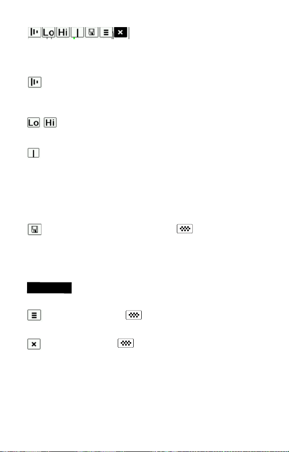
Utiliser les boutons de navigation Haut (déplacement vers la
gauche) et Bas (déplacement vers la droite) pour mettre les icônes
en surbrillance sur l'affichage graphique.
Zoom - Agrandit visuellement la forme d'onde des pics
affichés pour plus de visibilité. Appuyer à plusieurs reprises sur le
bouton (+) ou (-) permet d’augmenter/de diminuer le zoom.
la plage de mesure Lo ou Hi de l’instrument. (voir la page 5)
forme d'onde affichée. Utiliser les boutons (-)(+) pour déplacer la
ligne de curseur verte vers la gauche ou la droite de la forme
d'onde. La valeur d'épaisseur est affichée en haut à droite de la
ligne de curseur. Cette fonctionnalité est particulièrement utile
dans les applications multicouches où il y a plus de 3 couches
distinctes.
enregistrer une copie de l'image de l'écran actuel. Les 10
dernières captures d'écran sont enregistrées dans la mémoire et il
est possible d'y accéder lorsque l'instrument est connecté à un
ordinateur. (voir PosiSoft USB Drive en page 12)
Ra
simultanément pour capturer un écran..
de l'instrument.
Appuyer sur le bouton Up pour retourner à l'affichage graphique.
Set Range - Appuyer sur le bouton (-) ou (+) pour ajuster
Cursor - Le curseur permet de poursuivre l'analyse de la
Capture d’écran - Appuyer sur pour capturer et
cco
u
rci:
Appuyer et maintenir les boutons (-)(+)
Menu - Appuyer sur pour accéder au menu principal
Exit - Appuyer sur pour fermer l'affichage graphique.
10

Couches
(modèle Avancés uniquement)
Les modèles PosiTector 200 avancés sont capables d'afficher
numériquement jusqu'à 3 épaisseurs de couche individuelles dans
un système multicouche.
Sélectionner l’option de menu Couches (Layers) pour :
- Choisir jusqu'à 3 valeurs d'épaisseur de couche individuelle.
- Éditer le nom des couches et les couleurs du graphe de lot.
RQES:
Avant de régler l'instrument pour une mesure multicouche, il•
est recommandé de prendre d'abord des mesures en mode
simple couche et d'interpréter les résultats au moyen de
l'option Graphes. (voir la page 9)
Lorsqu'un lot est ouvert (Ouvrir), appuyer sur le bouton Haut•
pour visualiser le graphe du lot.
Gestion de la Mémoir
Gestion de la Mémoir
Le PosiTector 200 peut enregistrer des mesures dans sa
mémoire de stockage interne. Les valeurs stockées peuvent être
examinées à l'écran ou sont accessibles via des PC, des tablettes
PC et des smart phones. Les mesures sont horodatées.
Le modèle Standard stocke jusqu’à 250 valeurs dans un lot
uniquetore up to 250 readings in one batch.
Le modèle Avancé stocke 100 000 valeurs de mesure dans un
maximum de 1 000 lots. « Un nouveau lot » ferme tout lot
actuellement ouvert et crée un nom nouveau lot en utilisant le plus
petit numéro disponible. L’icône apparaît. Les nouveaux lots
sont horodatés au moment de leur création.
Faites défiler les modes
d'affichage (modèle avancé
uniquement)
Supprimer la dernière mesure
Accéder au menu
RQE:
Ce guide rapide résume les fonctions de base de l’instrument.
Téléchargez la notice d’instructions complète à l’adresse:
www.defelsko.com/manuals
Créer un nouveau lot
(Modèle avancé
uniquement)
Restaurer la luminosité
après occultation
(modèle avancé
uniquement)
11

Accès Aux Valeurs de Mesure Enregistrées
Accès Aux Valeurs de Mesure Enregistrées
Solutions PosiSoft de visualisation, analyse et reporting des
données:
PosiSoft USB Drive - connecter le PosiTector à un PC/Mac en
utilisant le câble USB fourni pour accéder aux mesures, graphes,
photos et captures d'écran. Il sera ensuite possible de les imprimer.
Aucun logiciel ni aucune connexion Internet n'est requise. USB
Drive must be selected. (see pg.13)
PosiSoft.net - une application web gratuite offrant un stockage
centralité et sécurisé des mesures d'épaisseur du PosiTector.
Accédez à vos données à partir d'un périphérique connecté à
Internet. Aller à: www.PosiSoft.net
PosiSoft Software - Logiciel de bureau pour le téléchargement, la
visualisation et l'impression de vos données de mesure.
PosiSoft Mobile (modèle Avancés uniquement) - accès aux valeurs de
mesure, graphes, captures photos et annotations de mise à jour via
des périphériques WiFi autorisés, comme les tablettes PC, les
smart phones et les PC.
Menu de Connexion
Menu de Connexion
(Connect)
(Connect)
Sync
Lorsque ce mode est sélectionné, l'instrument synchronise
immédiatement les valeurs de mesure enregistrées via USB,
Bluetooth ou WiFi vers l'application web PosiSoft.net. (PosiSoft
Desktop Manager et une connexion Internet sont nécessaires pour
l'utilisation d'un système de stockage de masse ou du Bluetooth.)
SYNC Auto
Cette option permet de synchroniser l'instrument automatiquement
avec PosiSoft.net au moment de la connexion initiale à un PC
connecté à l'Internet supportant l'application PosiSoft Desktop
Manager ou via un réseau WiFi local.
Les valeurs de mesure supplémentaires ajoutées dans la mémoire
durant la connexion sont uniquement synchronisées lorsque le
câble USB est débranché ou lorsque l'option Sync Now est
sélectionnée.
12

USB Drive
L'instrument utilise un périphérique de stockage de masse USB
qui fournit une interface simple pour récupérer les données d'une
manière similaire à celle employée par les lecteurs flash USB, les
appareils photographiques ou les lecteurs audio numériques.
RQE:
Une fois connecté, l'alimentation électrique est fournie via
le câble USB. Les piles ne sont pas utilisées et l’instrument n’est
pas mis automatiquement hors tension. L’instrument se comporte
comme un chargeur de batterie lorsque des piles rechargeables
(NiMH) sont installées.
Bluetooth
(modèle Avancés uniquement)
Cette fonctionnalité permet de transmettre des valeurs de mesure
individuelles vers un ordinateur ou un périphérique compatible
grâce à l’utilisation de la technologie sans fil Bluetooth. Voir
www.defelsko.com/bluetooth
WiFi
(modèle Avancés uniquement)
Autorise une communication sans fil avec des périphériques
comme les tablettes PC, les smart phones et les PC connectés à
votre réseau sans fil local ou un hot spot mobile nomade. Voir
www.defelsko.com/WiFi
Mises à jour
Cette option détermine si une mise à jour logicielle est disponible
pour votre instrument. Voir www.defelsko.com/update
ATTENTION:
L’instrument peut exécuter un Redémarrage à
froid (Hard Reset) après une mise à jour. (voir la page 8)
13

Remise en Service
Remise en Service
Avant de remettre l'instrument en service...
1.Installer des piles alcalines neuves dans le compartiment en
respectant la polarité.
2.Examiner la tête de sonde en cas de saleté ou
d'endommagement.
3.Procéder à un Redémarrage à froid (Hard Reset)
(voir la page 8) et à) une remise à Zéro (voir la page 5).
4.Placer une cale en plastique sur une surface dure (ex. verre) et
tenter une mesure (voir la page 4).
Si l'instrument doit être retourné pour service, décrire
complètement le problème et inclure les résultats de mesure (si
possible). Veiller à inclure l'instrument, à préciser le nom de
l'entreprise, du contact au sein de la société, le numéro de
téléphone ainsi que le numéro de télécopie ou l'adresse de
courriel.
Site Web: www.defelsko.com/support
Garantie Limitée, Recours
Garantie Limitée, Recours
et Responsabilité Limitée
et Responsabilité Limitée
La garantie, les recours et la responsabilité de DeFelsko sont la
garantie limitée, les recours et la responsabilité limitée mentionnés sur son site Internet à l’adresse: www.defelsko.com/terms
www.defelsko.com
© DeFelsko Corporation USA 2012
Ce manuel, tout droit réservé, est protégé par les lois sur les droits d'auteur et ne peut en aucun cas
être reproduit ou retransmis, en partie ou dans son intégralité, en aucune façon, sans la permission
écrite de DeFelsko Corporation.DeFelsko et PosiTector sont des marques de commerce de DeFelsko
Corporation déposées aux États-Unis et dans d'autres pays. Les autres marques ou noms de produits
sont des marques de commerce ou des marques de commerce déposées de leurs propriétaires respectifs.
Tous les efforts possibles ont été faits pour assurer que les informations contenues dans ce manuel
sont exactes. DeFelsko ne peut être tenu responsable pour aucune erreur d'impression ou d'écriture.
Tous droits réservés
14

Simple. Durable. Accurate.
Ultrasonic Coating Thickness Gage
www.defelsko.com
© DeFelsko Corporation USA 2012
This manual is copyrighted with all rights reserved and may not be
reproduced or transmitted, in whole or part, by any means, without
written permission from DeFelsko Corporation.
DeFelsko, PosiTector and PosiSoft are trademarks of DeFelsko
Corporation registered in the U.S. and in other countries. Other brand
or product names are trademarks or registered trademarks of their
respective holders.
Every effort has been made to ensure that the information in this manual
is accurate. DeFelsko is not responsible for printing or clerical errors.
All Rights Reserved
 Loading...