

Page 1
PosiTector UTG
INSTRUCTION MANUAL v. 2.2
for UTG ME models
Simple. Durable. Accurate.
Ultrasonic Thickness Gage
Page 2
Introduction
Introduction
2
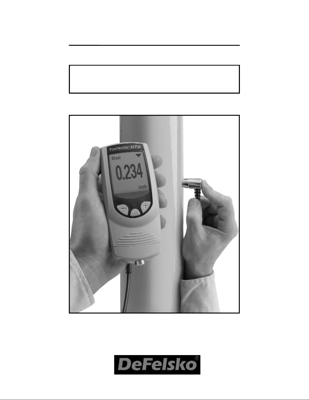
The PosiTector UTG ME is a hand-held Ultrasonic
Thickness Gage that uses the non-destructive ultrasonic pulse-echo principle to measure the wall thickness of a wide variety of materials. The default and
most common setting for the PosiTector UTG is
multiple-echo (ME) mode. In ME mode the Gage
measures the metal thickness of a painted structure,
disregarding the paint thickness. The user can
switch the gage to single-echo mode by selecting SE
Mode from the Gage menu (see pg.15).
The probe (a single element contact transducer)
transmits an ultrasonic pulse into the material to be
measured. This pulse travels through the material
towards the other side. When it encounters an interface such as air (back wall) or another material, the
pulse is echoed back to the probe. The time required
for the pulse to propogate through the material is
measured by the Gage, represented as t
1
and t
2
below.
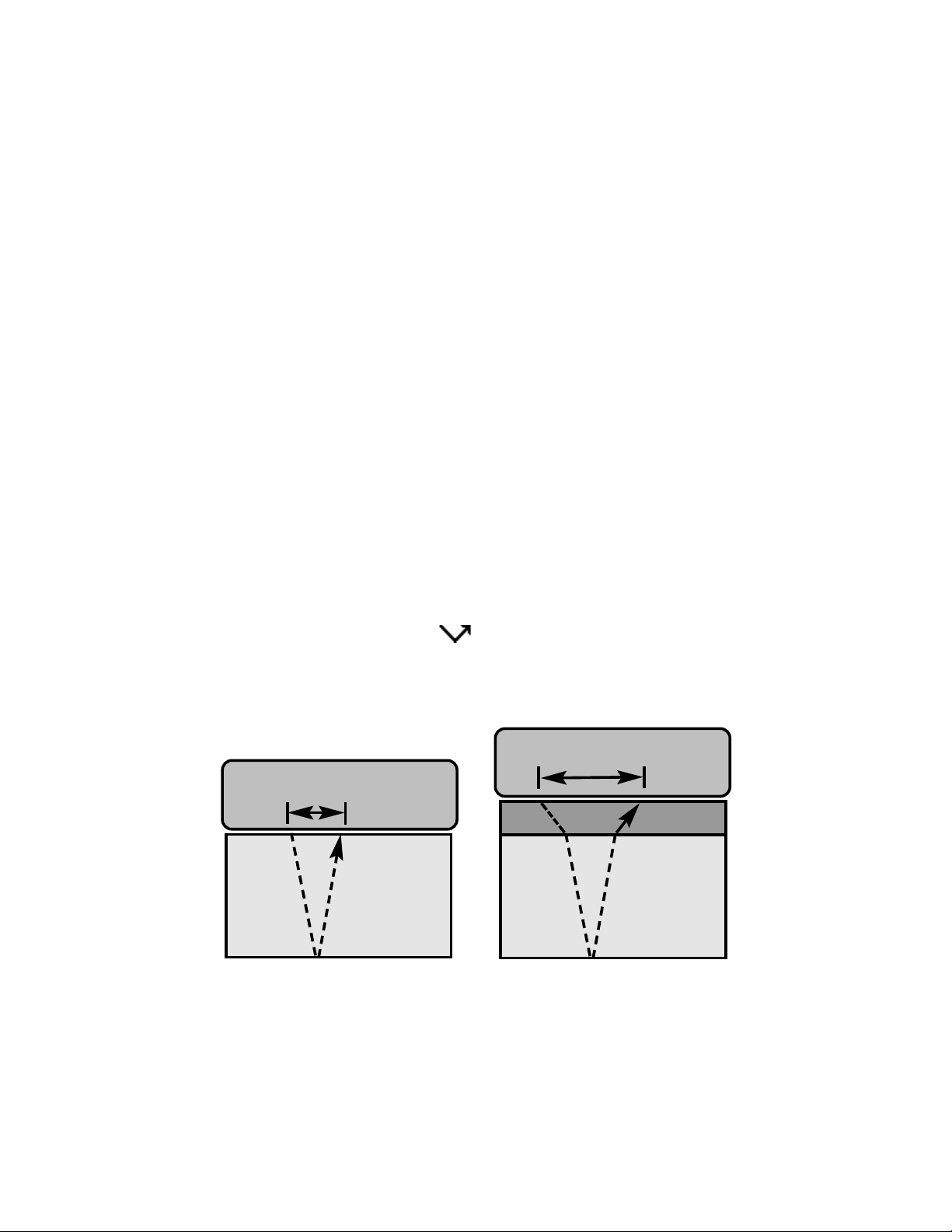
In single-echo mode (see Figure 1) the Gage
determines thickness by measuring t1(uncoated) or
t2 (coated), dividing it by two and then multiplying by
the velocity of sound for that material (steel).
steel
coating
steel
2
t
>
1
t
For uncoated materials t1relates directly to material
thickness. When a material is coated the propaga-
tion time is increased and is shown above as t
2
.
Coatings such as paint have a slower velocity of
Figure 1
2
t
1
t
Probe
Probe
Page 3
3
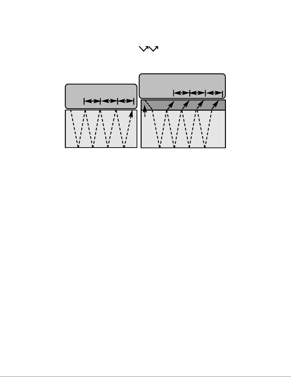
In multiple-echo mode the Gage determines
thickness by measuring the time between at least
three consecutive back wall echoes.
steel
In the figure above, multiple-echo mode measures
only the time between echoes. Regardless of
whether the steel is coated or not, all times between
echoes are the same. In multiple-echo mode
the Gage determines thickness by measuring
t
1+t2+t3
, dividing it by six and then multiplying by the
velocity of sound for that material. The resultant
thickness calculation made by the instrument is
therefore an accurate measurement of the steel
thickness only, disregarding the coating thickness.
The velocity of sound is expressed in inches per
microsecond or meters per second. It is different for
all materials. For example, sound travels through
steel faster (~0.233 in/µs) than it travels through
plastic (~0.086 in/µs).
Probe
1
t
2
t
3
t
1
t
2
t
3
t
Coating
Figure 2
Operation Overview
Operation Overview
1. Turn the Gage ON (see Power-Up - pg. 5)
2. Verify accuracy (see Verification - pg. 9)
3. Select the correct velocity of sound (see pg. 10)
4. Measure the part (see How to Measure - pg. 5)
Probe
sound than that of metal. Thus the single-echo technique will produce a thickness result greater than the
actual combined coating+metal thickness.
Page 4
4
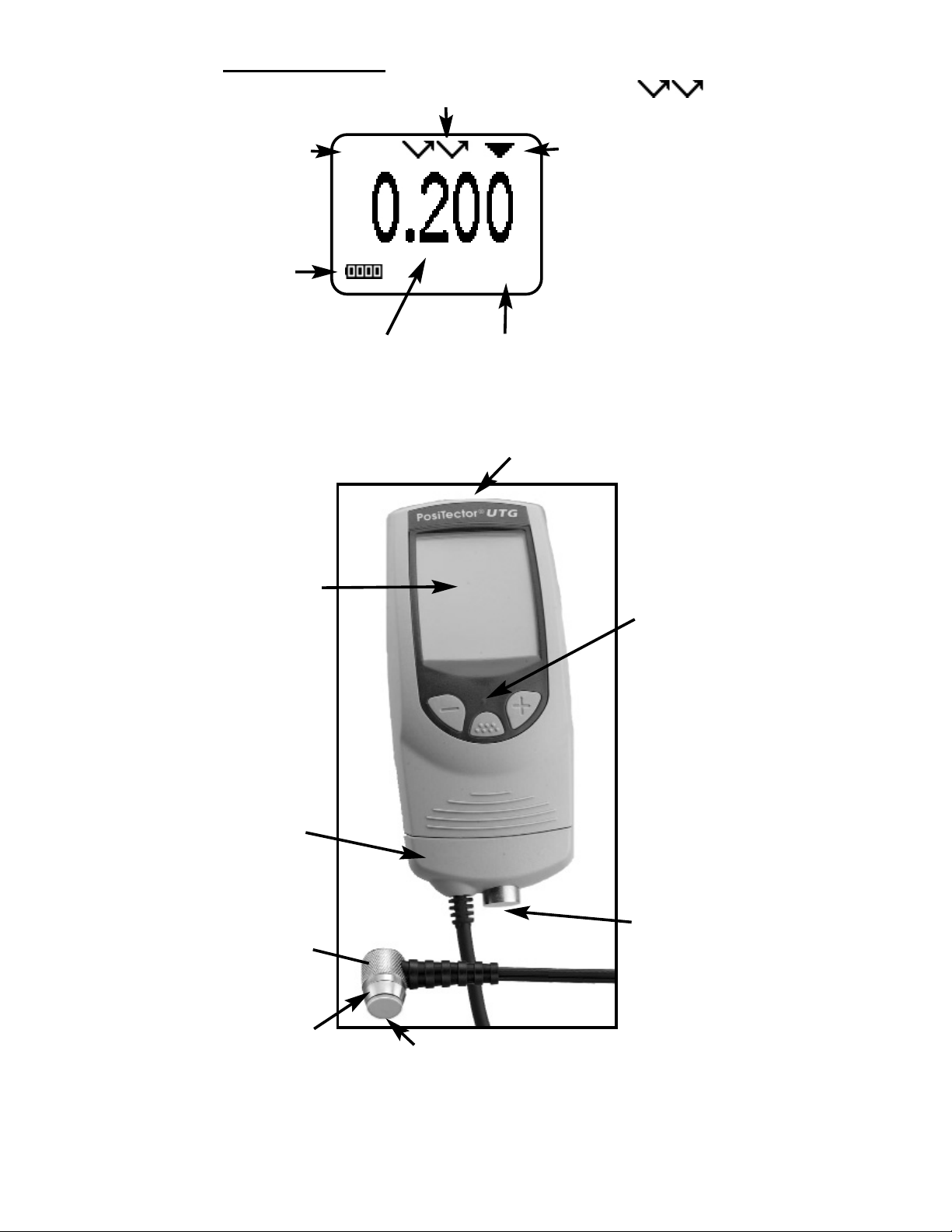
Zero
Plate
Finger
Grip
Wear Face
(Measurement Head)
USB/IR Port
Probe
connector
Bi-color
indicator
light
Display
Probe
(transducer)
Typical Display
Current
Measurement
Currently
selected
material
Unit of
Measurement
The Coupled
Symbol appears
when the probe
is ultrasonically
connected with a
surface.
inch
Steel
Battery
Icon
Measurement Mode Currently set to ME
Page 5
5
How to Measure
How to Measure
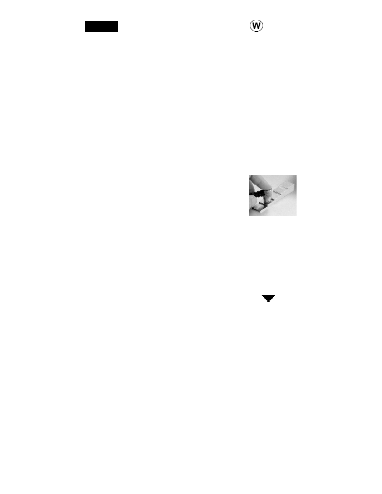
1. Remove black rubber cap from probe
if supplied. Couplant (glycol gel included) must be applied to the surface
to be tested to eliminate air gaps
between the wear face and the surface. A single
drop of couplant is sufficient when taking a spot
measurement.
2. Place the probe flat on the surface. Use moderate pressure to press against the top of the probe
with the thumb or index finger. When the probe senses echoed ultrasound, a coupled symbol will
appear on the display and thickness values will be
displayed. While the probe is coupled, the
PosiTector UTG will perform 3 readings per second,
updating the display each time.
3. When the probe is removed from the surface, the
last measurement will remain on the display.
Occasionally, excess couplant will remain on the
probe when the probe is lifted from the surface. This
may cause the PosiTector UTG to display a final
measurement value different from those observed
when the probe was on the surface. Discard this
value and repeat the measurement.
Power-up / Power-down
Power-up / Power-down
The PosiTector UTG powers-up when any button is
pressed. To preserve battery life, the Gage powersdown after approximately 3 minutes of no activity. All
settings are retained.
Throughout this manual, the symbol
indicates more information about the particular topic
or feature is available on our website.
Go to: www.defelsko.com/manuals
NOTE:
Page 6
6
Surface Conditions
Surface Conditions
Ultrasonic measurements are affected by the
condition, roughness and contour of the surface to
be tested.
Measurement results may vary on coarse surfaces.
Where possible, it is recommended to seat the
transducer on a smooth flat surface that is parallel to
the opposite side of the material.
On rough surfaces, the use of a generous amount of
couplant minimizes the surface effects and serves to
protect the transducer from wear, particularly when
dragging the probe across a surface.
On smooth, uncoated metal
surfaces the Gage (in ME mode) may occasionally
be unable to give a measurement result even when
the "coupled" symbol appears. Use additional
couplant and lighter pressure on the probe when
measuring. Alternatively, laying a plastic shim on the
surface with couplant applied to both sides to
simulate a painted surface will help produce a steelonly thickness measurement (multiple-echo mode).
Switching the Gage to SE mode (see pg.15) will also
help produce a steel-only thickness measurement.
Zero Menu Option
Zero Menu Option
The PosiTector UTG probe can be "zeroed" to com-
pensate for temperature and wear. This action is not
required when operating in ME (multiple-echo) mode
except when the Gage is new and after a Reset (pg.
16). However it ensures best accuracy when operating in SE (single-echo) mode. Therefore it is a good
idea to "zero" the probe before each work shift and
when the temperature of the part changes. During
zeroing, it does not matter what the current velocity
setting is.
Zero
ME Mode Note:
Page 7

7
Menu Operation
Menu Operation
Gage functions are menu controlled. To access the
Menu, turn the Gage on, then press the button.
3. Select the Zero menu option
(LCD will display image shown
in Figure A). Hold the probe in
the air and press the button
to select OK to continue.
Figure A
4. When the image shown in
Figure B is displayed, press
and hold the probe against the
zero plate.
5. When the Gage beeps and the
image shown in Figure C
appears, remove the probe
from the zero plate.
Figure C
Figure B
The Gage will display 0.00.
DO NOT place probe on the Zero plate
until Step 4.
Important:
1. Make sure the Gage is on and the probe is
wiped clean.
2. Apply a single drop of couplant onto the zero
plate located on the underside of the Gage. DO
NOT apply couplant directly onto the probe face.
Current selection is displayed
with darkened background
Reset
Gage Info
Flip Display
Units
Set Clock
Language
Memory
Zero
Cal Settings
SE Mode
✓
HiLo Alarm
Setup
Some menu items have a tick box
to their right to indicate current
status. An empty box indicates
that feature in not active.
Page 8

8
“Focus” is currently
at this unselected
(empty) Radio
button
“Radio” buttons.
Only one can be
selected at a time.
“List“ box
a “tick” indicates this
square box has
been selected
Calibration, Verification
Calibration, Verification
and Adjustment
and Adjustment
Three steps ensure best accuracy…
1.Calibration - typically done by the manufacturer
or a qualified lab
2.Verification of Accuracy - as done by the user
3.Adjustment - to a known thickness or sound
velocity for the material to be measured
Calibration
Calibration is the controlled and documented
process of measuring traceable calibration
To navigate, press (-) to scroll DOWN, (+) to scroll UP
and to SELECT. Press both (-)(+) buttons at any
time to exit any menu or select Exit from the Menu.
List boxes have a down arrow on the right-hand side.
Use the (-) and (+) buttons until your desired choice
appears, then press to select this choice and
move focus onto the next item.
Page 9

9
Verification
Gage accuracy can and should be verified using
known reference standards of the material to be
tested.
Verification is an accuracy check performed by the
user using known reference standards. A successful
verification requires the Gage to read within the
combined accuracy of the Gage and the reference
standards.
Calibration step blocks are available for this
purpose. But while they are valuable for verifying
gage accuracy to tight, traceable tolerances, they
may not represent the actual material to be
measured.
Therefore a reference standard can also be a small
piece of the material to be measured. If the actual
material is not available, material of the same
composition (sound velocity) can be used. Thickness
can be determined with alternate means such as a
Certification: All PosiTector UTG instruments ship
with a Certificate of Calibration. For organizations
with re-certification requirements, gages may be
returned at regular intervals for calibration.
DeFelsko recommends that customers establish
gage calibration intervals based upon their own
experience and work environment. Based on our
product knowledge, data and customer feedback, a
one year calibration interval from either the date of
calibration, date of purchase, or date of receipt is a
typical starting point.
standards and verifying that the results are within the
stated accuracy of the Gage. Calibrations are
typically performed by the Gage manufacturer or by
a certified calibration laboratory in a controlled
environment using a documented process.
Page 10

The PosiTector UTG allows four simple adjustment
choices. All four methods are based on the simple
10
Adjustment
Adjustment, or Calibration Adjustment is the act of
aligning the Gage's thickness readings to match that
of a known reference sample.
The PosiTector UTG is factory calibrated. But in
order for it to take accurate thickness measurements
of a particular material it must be set to the correct
sound velocity for that material. Be aware that
material composition (and thus its sound velocity)
can vary from stated tables and even between lots
from a manufacturer. Adjustment to a sample of
known thickness of the material to be measured
ensures that the Gage is adjusted as close as
possible to the sound velocity of that specific
material. Samples should be flat, smooth and as
thick as the maximum expected thickness of the
piece to be tested.
Cal Settings
micrometer. If the Gage does not measure the
sample within the combined tolerances of the Gage
and the micrometer, the Gage can be adjusted (see
below). For best accuracy this process should be
repeated if the temperature of the part changes
substantially.
To guard against measuring with an improperly
adjusted Gage, verify the Gage at the beginning and
the end of each work shift. During the work shift, if
the Gage is dropped or suspected of giving
erroneous readings, its accuracy should be reverified. In the event of physical damage, wear, high
usage, or after an established calibration interval; the
Gage should be returned to the manufacturer for
repair or calibration.
Page 11

11
Thickness
1.Apply a drop of couplant onto the reference
standard.
2.Measure the reference standard.
3.Lift the probe. Select the Cal Settings
Thickness menu option.
4.Adjust the display down (-) or up (+) to the
reference standard thickness.
5.Press to store the adjustment and exit.
premise of adjusting the sound
velocity. The first three
adjustment methods make 1point calibration adjustments to
optimize the linearity of the
Gage over small ranges. The
Thickness
Material
Velocity
2 Pt Adjust
fourth method makes a 2-point calibration
adjustment to allow for greater accuracy over a large
range.
The most common method of adjustment is to measure a sample of known thickness. Select a reference
standard of material as close as possible in composition to the intended application. For best results,
the thickness of the reference standard should be
equal to or slightly greater than the thickness of the
part to be measured.
Material
If a known thickness of the material is not available,
but the material is known, this quick adjustment
allows the user to load one of several
preprogrammed material velocities.
1. Select the Cal Settings Material menu option.
2. Scroll to the desired material.
3. Press to store the adjustment and exit.
Page 12

12
2 Pt Adjust
A 2-Point adjustment allows for greater accuracy
while simultaneously adjusting probe zero. Select
two reference standards as close as possible in
composition to the intended application. For best
results, the thickness of the thicker reference
standard should be equal to, or slightly greater than
the thickest part to be measured. The thickness of
the thinner reference standard should be as close as
possible to the lower end of the expected
measurement range.
1. Select the Cal Adjust 2 Pt Adjust
menu option.
2. Measure the thinner reference sample.
3. Lift the probe from the sample and adjust the display down (-) or up (+) to the expected thickness.
4. When the expected thickness is reached, press
5. Measure the thicker reference sample.
6. Lift the probe from the reference sample and
adjust the display down (-) or up (+) to the
expected thickness.
7. Press to store the adjustment and exit.
Velocity
If the sound velocity for the test material is known,
the Gage can be adjusted to that specific sound
velocity by performing the following steps.
1.Select the Cal Adjust Velocity menu option.
2.Adjust the display down (-) or up (+) to the
desired velocity. Holding the (-) or (+) buttons
increases the rate of change.
3.When the desired velocity is reached, press
to store the adjustment and exit.
Page 13

13
Memory Management
Memory Management
The PosiTector UTG can record 10,000
measurements in up to 1000 groups (batches) for
on-screen statistical purposes, printing to an optional
IR printer, or for downloading to a personal computer
(optional PosiSoft software and USB cable
required).
Memory
New Batch
When a batch is open, create a new batch
by pressing (+)
Shortcut:
Closes current batch and creates a new batch name
using the next higher number. For example, if only
Batch 1 and Batch 3 exist, then Batch 4 would be
created and made the current batch. The icon
appears and statistics are displayed and each
measurement will now be simultaneously shown on
the display and stored into this new batch. On screen
statistics are immediately updated with each
measurement. New batch names are date stamped
at the time they are created.
Open
Selects a previously created batch name to open
and make current. If it contains measurements, onscreen statistics will immediately reflect values
calculated from this batch.
Mean
(average)
Standard
Deviation
No. of
measurements
Max and Min
values
Current
Batch
Last
reading
Memory Icon
Page 14

Print
Prints all stored measurements to the optional IR
printer or to a PC’s default Windows printer via the
optional USB cable and PosiSoft software. Press
(-)(+) simultaneously to cancel printing.
Downloading Measurements Stored in Memory
Measurements stored in the Gage's memory (in
batches) can be downloaded to a computer using
optional PosiSoft software and USB cable.
Measurements are not erased from memory after
downloading.
PosiSoft® allows entry of notes and annotations,
prints histograms and basic charts, manages data,
and readings can be exported to a document or
spreadsheet.
Remove the last reading from the current
open batch by pressing (-).
NOTE:
14
To delete a value, scroll to that value (align the “+”
symbol beside it) then either take another
measurement to change it, or press to delete it
or exit. Statistics are updated.
View
Lists all readings on the display from the current or
most recently used batch. It begins by showing the
last 10 measurement values. Scroll using the (-) or
(+) buttons. Hold for 1 second to scroll a page at a
time.
Delete
Removes a batch completely from memory. The
name is deleted and all measurements are erased.
Close
Stops the recording process, closes the current
batch, and removes the statistics from the display.
Page 15

15
When HiLo Alarm is first selected, the current Lo
setting is displayed. Adjust down (-) or up (+).
Alternatively, measure a material with a thickness
close to the required value and make final
adjustments with the buttons. Select to accept
this value. The current Hi setting is now displayed.
This mode allows the Gage to visibly and audibly
alert the user when measurements exceed userspecified limits.
Hi Lo Limits (Alarm)
Hi Lo Limits (Alarm)
HiLo Alarm
The default and most common setting for the
PosiTector UTG is multiple-echo mode
The user can switch the gage to single-echo
mode by selecting SE Mode from the Gage menu
- To detect pits and flaws
- To increase the measurement range
- To obtain thickness measurements in
circumstances where multiple-echo can not
Single Echo Mode
Single Echo Mode
SE Mode
✓
Press (-) to quickly toggle between ME
and SE measurement modes.
Shortcut:
Follow the same procedure to adjust this setting.
The icon will appear on the display.
All measurements will now be compared to your
defined limits. The Gage LED blinks green if results
are within those limits or red if readings are outside
set limits. A single low tone will display if it is below
the Lo limit, and a HIGH tone if it is above the Hi limit.
Page 16

All batches are date-stamped when created, and all
measurements are time-stamped (24 hour format)
when stored into these batches. It is therefore important to keep both the date and time current using this
menu button. Alternatively, the date and time can be
automatically updated when the gage is connected
to PosiSoft using the Gage Utilities -> Set Clock function in PosiSoft.
Set Clock
This menu button converts the display and all stored
readings from inch to mm or vice versa.
Units
16
A more thorough Reset can be performed by holding
the (+) button when the Gage is powered down until
the Reset symbol appears. It performs the same
function as a menu Reset with addition of Units =
inch, and Language = English.
Date and Time are not affected by any Reset.
NOTE:
Reset restores factory settings and returns
the Gage to a known, out-of-the-box
condition. It is handy when you want to “start all
over”.
The following occurs:
- all batches are closed and stored measurements
are erased.
- calibration adjustments are cleared and returned
to the Gage’s factory calibration settings.
- menu setting are returned to the following:
Memory = OFF HiLo Alarm = OFF SE Mode = OFF
Reset
Setup Menu
Setup Menu
Setup
Page 17

17
Troubleshooting
Troubleshooting
Some common reports received by our Service
Department along with possible causes. Most conditions however can be cleared with a Reset (pg. 16).
Probe continues to measure after lifted from
surface
Wipe away any excess couplant on probe tip.
Gage fails to power down
Ensure the probe is clean and free of couplant. The
Gage will not turn off if coupled symbol is
displayed on LCD.
Gage is coupled, but not measuring
See Surface Conditions, pg. 6.
The surface temperature of the test piece should not
exceed (150° C / 300° F)
Application Notes
Application Notes
Measuring on hot surfaces
Measurements taken at higher temperatures (above
100° C / 212° F) require special consideration. Both
material sound velocity and probe zero will change
with temperature. For maximum accuracy at high
temperatures, adjustment should be performed
using a material of known thickness heated to the
temperature where measurements are to be
performed. The probe should remain on the surface
only as long as it takes to get a measurement.
Gage readings appear to be double the expected thickness
This sometimes occurs near the minimum measuring range of the instrument (0.100" or 2.5mm). The
first return echo is unmeasurable, so the gage measures the second return echo. The resultant calculation is double the actual thickness.
Page 18

18
This image appears if the memory of the
gage has become corrupt. This can occur in
the event that the gage batteries were removed
while the instrument was powered-on and the gage
was not able to self power-down. If this message
appears it will be followed by a full reset. All readings
in memory will be erased and gage settings will be
reset to "out-of-the-box" settings.
To retain all user settings and stored memory readings, only replace the batteries after the
Gage has automatically powered-down.
-Nickel-cadmium and nickel-metal hydride rechargeable batteries will work but the Gage may appear to
have weak batteries.
Changing The Batteries
Changing The Batteries
The battery icon displays four bars with fresh
alkaline batteries installed. As the batteries weaken,
the number of bars will be reduced. When the batteries become very weak the Power Warning
image will display and the Gage will
automatically power-down. To maintain user settings and stored measurements, the batteries must be
replaced. USE ONLY “AAA” ALKALINE
BATTERIES
NOTES:
Power Warning
Measurement jumps as probe is lifted from
surface
Occasionally, excess couplant will remain on the
probe when the probe is lifted from the surface. This
may cause the PosiTector UTG to display a final
measurement value different from those observed
when the probe was on the surface. Discard this
value and repeat the measurement.
Gage displays -.-- (dashed lines) when measuring on an smooth uncoated surface in ME mode
See ME Mode Note, pg. 6
Page 19

Technical Data
Technical Data
Conforms to: ASTM E797
19
Returning for Service
Returning for Service
Before returning the Gage for service…
1.Install new Alkaline batteries in the proper
alignment as shown within battery compartment.
2.Examine the probe tip for dirt or damage.
3.Perform a Reset (pg.16) and a Zero (pg.6)
If you must return the Gage for service, describe the
problem fully and include measurement results, if
any. Be sure to also include the probe, your
company name, company contact, telephone
number and fax number or email address.
Website: www.defelsko.com/support
Measurement Range*
Single-Echo
Multiple-Echo
0.100" to 5.000"
0.100" to 2.500"
2.50 to 125 mm
2.50 to 60 mm
Resolution
0.001 in. 0.01 mm
Accuracy
+ 0.001 in. + 0.03 mm
Velocity Range
0.0492 to 0.393 in/µs 1250 to 10,000 m/s
Measurement Rate
3 readings/second
Gage: 0 to 50° C (+32° to +120° F)
Probe: -20° to 55° C (-4° to +131° F) continuous
Material Surface Temp -40° to +150° C (-40° to +300° F)
Operating Range:
*Measurement range is for carbon steel and depends
upon surface condition, temperature and material.
Gage body dimensions:
146 x 64 x 31 mm (5.75" x 2.5" x 1.2")
Battery Life: 80 hours continuous ( >100 hours idle)
Page 20

www.defelsko.com
© DeFelsko Corporation USA 2007
All Rights Reserved
This manual is copyrighted with all rights reserved and may not be reproduced or
transmitted, in whole or part, by any means, without written permission from
DeFelsko Corporation.
DeFelsko, PosiTector and PosiSoft are trademarks of DeFelsko Corporation registered in the U.S. and in other countries. Other brand or product names are trademarks or registered trademarks of their respective holders.
Every effort has been made to ensure that the information in this manual is accurate. DeFelsko is not responsible for printing or clerical errors.
20
Limited Warranty, Sole Remedy
Limited Warranty, Sole Remedy
and Limited Liability
and Limited Liability
DeFelsko's sole warranty, remedy, and liability are
the express limited warranty, remedy, and limited
liability that are set forth on its website:
www.defelsko.com/terms
Available Options
Available Options
A variety of accessories are available to help you get
the most from your PosiTector UTG ultrasonic
thickness gage.
 Loading...