

DeFelsko PosiTector RTR Full Manual

Introduction ......................................................... 1
Kit Contents ........................................................ 1
Quick Start .......................................................... 1
Certification ......................................................... 2
Probes ................................................................. 4
How to Measure .................................................. 5
Calibration & Verification of Accuracy ................. 8
Menu Operation .................................................. 9
Statistics .............................................................. 9
Cal Settings Menu ............................................... 10
Zero ................................................................ 10
Tape Grade .................................................... 10
Linearize ........................................................ 11
Setup Menu ......................................................... 12
Reset .............................................................. 12
Gage Info ....................................................... 12
Memory Management ......................................... 14
Standard Models ........................................... 14
Advanced Models .......................................... 15
Annotate ......................................................... 16
Display ........................................................... 17
Summaries ..................................................... 18
Screen Capture .............................................. 18
Accessing Stored Measurement Data ................ 19
PosiSoft Desktop Manager (PDM) ................. 19
PosiSoft.net .................................................... 20
PosiSoft Software .......................................... 20
PosiSoft Mobile .............................................. 21
Table of Contents
Table of Contents

Connect Menu ..................................................... 22
Sync Now ....................................................... 22
Auto Sync ....................................................... 22
USB Drive ...................................................... 22
Bluetooth ........................................................ 24
Bluetooth Wireless Printer ............................. 25
WiFi ................................................................ 25
Updates .......................................................... 26
Power Supply / Battery Indicator ........................ 27
Rechargeable Batteries ...................................... 27
Additional Accessories ........................................ 27
Technical Data .................................................... 30
Returning For Service ......................................... 31
Warranty .............................................................. 31

1
Introduction
Introduction
The PosiTector Replica Tape Reader (RTR) is a hand-held
electronic instrument that measures burnished
TestexTMPress-O-FilmTMreplica tape to produce peak-to-valley
surface profile height measurements. It consists of a body
(Standard or Advanced) and probe.
Quick Start
Quick Start
The PosiTector RTR powers-up when the center navigation
button is pressed. To preserve battery life, the Gage powers
down after approximately 5 minutes of no activity. All settings are
retained.
To ensure best accuracy, the user will be required to zero
the probe every time the Gage is powered-up. It is therefore a
good idea to clean the probe regularly with the included cleaning
card. Cleaning is best performed when the Gage is powered down.
NOTE:
With the Gage powered down...
1. Clean the probe with the included cleaning card. (pg. 7)
2. Power-up Gage by pressing the center navigation button.
3. Zero the probe. (pg. 10)
4. Measure the included check shim to verify accuracy. (pg. 8)
5. Measure the burnished replica tape. (pg. 7)
PosiTector RTR Kit Contents
- PosiTector body (Standard or Advanced)
- PosiTector probe (RTR-H)
- Stainless steel burnishing tool
- Cleaning cards (5)
- Surface cleaning putty
- Check shim
- Protective lens shield
- Wrist strap
- 3 AAA alkaline batteries
- Quick Guide instruction booklet
- Protective rubber holster with belt clip
- Nylon carrying case with shoulder strap
- USB Cable
- Certificate of Calibration traceable to NIST
- PosiSoft.net account
- Two (2) year warranty on Body and Probe
2
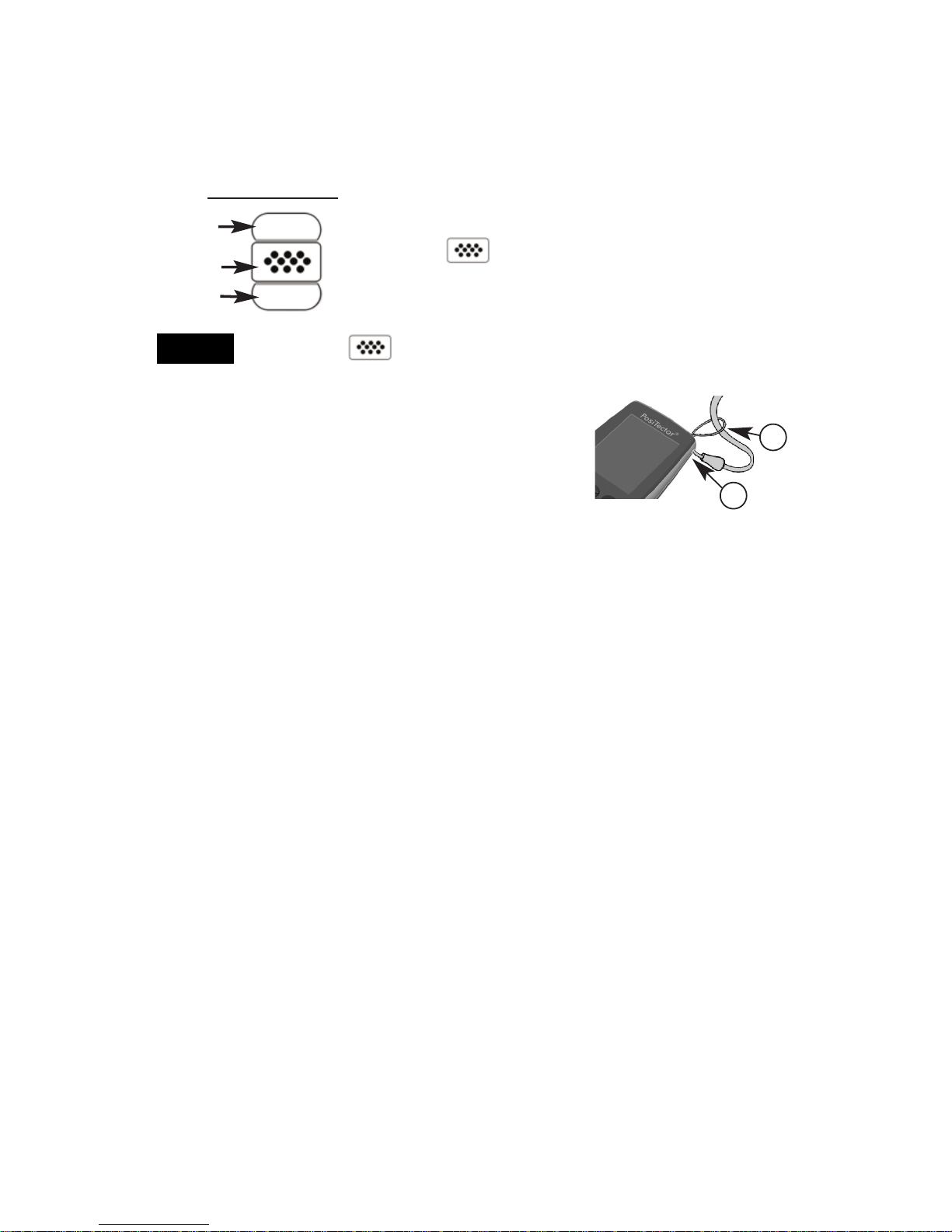
Up
Down
Center
To navigate, use the Up and Down buttons to
scroll and to SELECT.
Select Exit to exit from any menu.
Navigation Button
The center button is purposely recessed to help
eliminate unintentional powering-up of the Gage.
Menu Operation
Menu Operation
Gage functions are menu controlled. To access the Menu,
power-up the Gage, then press the center navigation button.
NOTE:
Certification
PosiTector RTR probes include a Certificate of Calibration.
For organizations with re-certification requirements, instruments
may be returned at regular intervals for calibration.
DeFelsko recommends that customers establish calibration
intervals based upon their own experience and work environment.
Based on our product knowledge, data and customer feedback, a
one year calibration interval from either the date of calibration, date
of purchase, or date of receipt is a typical starting point.
Wrist Strap
We recommend attaching and wearing the
supplied wrist strap.
1
2
Protective Lens Shield
The LCD is covered with a thin plastic film for protection against
fingerprints and other marks during shipment. This film, while
usually removed before using the Gage, can be left in place to
protect against paint overspray or debris. Replacements can be
purchased.
3
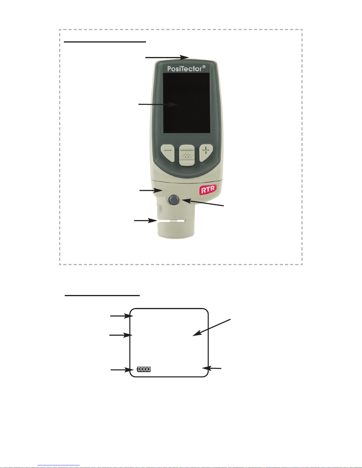
USB Port
LCD Display
Probe Connector
PosiTector Body
Typical Display
Current
Measurement
Unit of Measurement
thou/mils
Battery Icon
2.1
Measurement
Opening (Anvils)
Button Operated
Spring Micrometer
applies constant
anvil pressure
XC
H
L
Tape Grade
Linearize
Mode (pg. 11)

4
Probes
Probes
To disconnect a probe from a body, power-down the
Gage and slide the plastic probe connector horizontally
(in the direction of the arrow) away from the body.
Reverse these steps to attach a new probe.
When powered-up, the PosiTector automatically
determines which probe is attached and does a
self-check.
Additionally, the PosiTector accepts a number of probe types
including magnetic and eddy current coating thickness, surface
profile, environmental and ultrasonic wall thickness probes.
Perform the latest software Updates (pg. 26) to ensure probe
compatibility with your Gage. For the latest information on probe
interchangeability see www.defelsko.com/probes
5
How to Measure
How to Measure
Prepare the test surface
Burnish the replica tape (create a replica)
1. Prepare the test surface
2. Burnish the replica tape
3. Prepare the Gage
4. Measure
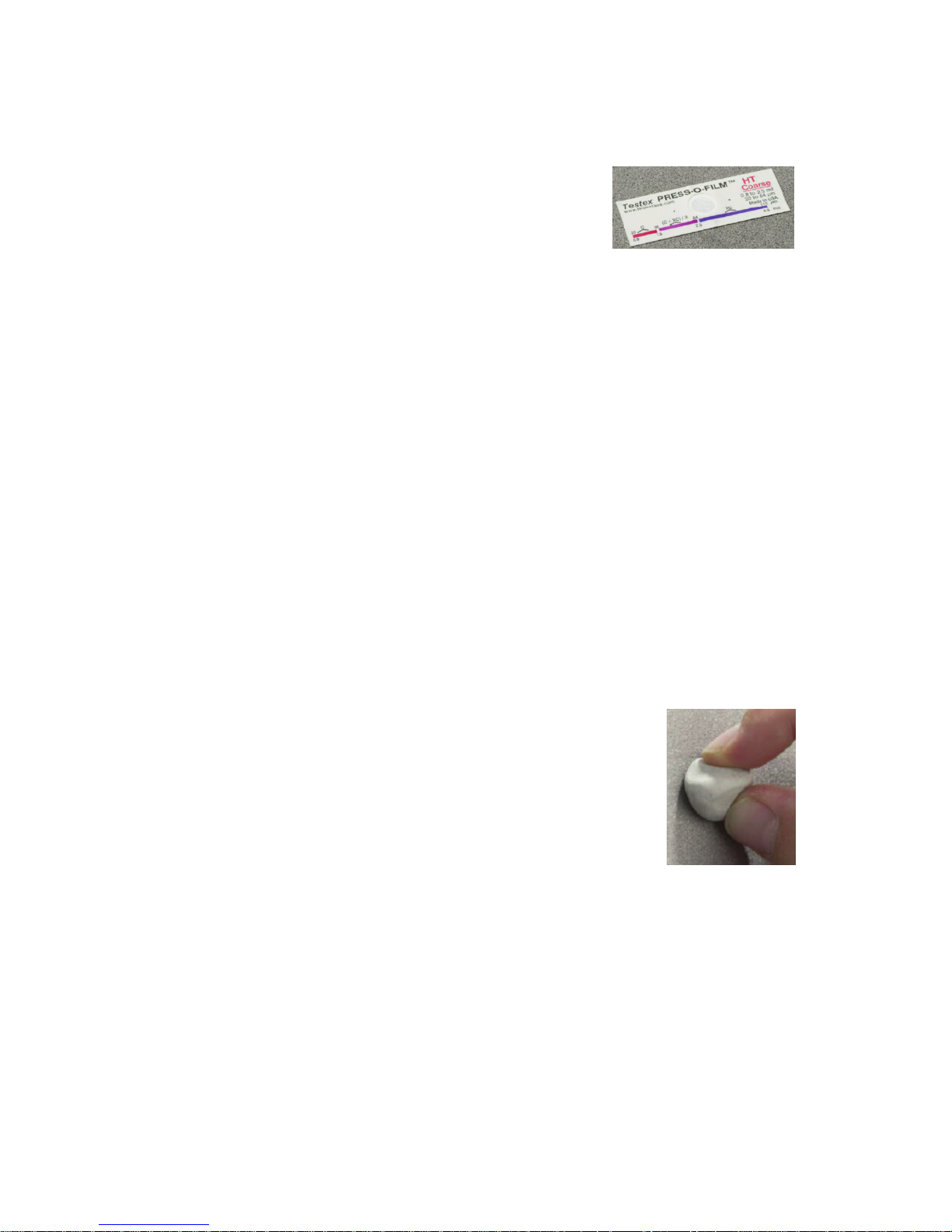
Locate a representative site for measurement.
Clean the surface to be tested. DeFelsko
recommends the use of the included putty to
remove dust, debris, or residual blast media from
the surface. Firmly press the putty onto the surface
using your fingers, and remove.
Press-O-Film Replica Tape
Press-O-Film Replica Tape
Press-O-Film provides a simple way to obtain an impression of a
surface for analysis. It consists of a layer of crushable plastic micro
foam affixed to a 50.8 µm (2 mil)
incompressible polyester film. When
compressed against a roughened surface, the
foam collapses and acquires an accurate
impression, or reverse replica, of the surface. It is available in a
number of grades to accommodate measurements in different
profile ranges.
Placing the compressed tape (replica) into the PosiTector RTR
gives a measure of the average maximum peak-to-valley height of
the surface roughness profile. The Gage automatically subtracts
the thickness of the polyester substrate from all measurements.
Select the appropriate grade of replica tape based on the target
profile. See tape instructions for assistance.
Pull a single adhesive-backed replica tape free of its release paper.
A “bull’s eye” circle of paper should remain on the release paper
(it is not used for measurement).
6
Apply replica tape to blasted surface. Press the adhesive-backed
ends of the paper to hold it firmly in place during the burnishing
process.
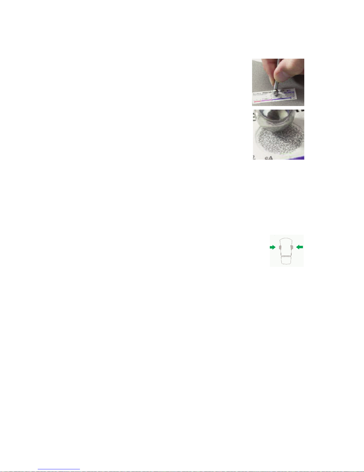
Firmly compress replica film using the rounded end
of the included stainless steel burnishing tool.
Apply sufficient pressure in a circular and x-y
rubbing motion to produce a replica with a uniform
pebble grain appearance. It normally takes 30 to 60
seconds to fully compress all parts of the film on
most surfaces. In general, too much compression is
safer than too little. After burnishing is complete,
remove the replica tape from the surface.
Prepare the Gage
With the Gage powered-down, clean the measurement surfaces
using the included cleaning card. Swipe the card through the
opening a few times while firmly pressing both probe buttons to
remove dust particles and residual tape adhesive.
Power-up the Gage by pressing the center navigation
button. An image appears indicating that the probe
requires zeroing.
Simultaneously press and hold both probe buttons firmly until the
Gage beeps and the arrows point outward. Do not place anything
in the measurement opening during this procedure.
Measure the included check shim to verify accuracy (pg. 8).
Ensure the correct grade of replica tape, C or XC, is displayed in
the upper left corner of the LCD (pg. 10).
7
The probe contains two measuring surfaces that can become
contaminated with dust particles and residual tape adhesive. It is
therefore a good idea to clean the probe regularly with the included
cleaning card. Cleaning is essential prior to performing a probe
zero (pg. 10) or a verification of accuracy (pg. 8). It is best
performed when the Gage is powered down.
With the Gage powered-down, swipe the card through the opening
a few times while firmly pressing both probe buttons.
The card can also be used to clean the surfaces of analog spring
micrometers. Replacement cards are available from your dealer.
Cleaning Card
Measure
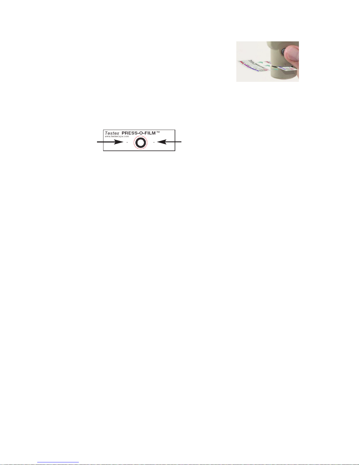
Insert the burnished replica tape into the
measurement opening. Ensure the tape is
properly positioned so that the burnished region
is centered within the opening in the probe with
the adhesive (sticky) side down.
To position the tape, move the tape to the back of the probe and
align the two dots (printed on replica tape) with arrows on both
sides of the measurement opening.
If you are using older tape that does not have the printed dots,
simply align by centering the tape within the measurement
opening.
Once positioned, firmly press both probe buttons simultaneously
and hold until the Gage beeps and the measurement is displayed.
During measurement, a constant anvil pressure is applied to the
replica tape regardless of how hard the two buttons are pressed.
The Gage automatically subtracts the 50.8 μm (2 mil) of
incompressible polyester film. No further adjustments are required.
Align dots with arrows on probe

8
Verification of Accuracy
Gage accuracy is verified using the included check shim.
Ensure that the probe has been cleaned with the included
cleaning card and that the probe has been zeroed (pg. 10).
Place the check shim into the measurement opening.
The average of several measurements should be within the
combined tolerance of both the Gage and the shim. If not, the
Gage may need to be returned to your dealer for service.
The check shim is specifically intended for the PosiTector RTR.
The Gage is designed to measure burnished replica tape within a
limited measuring range and automatically subtracts 50.8 μm
(2 mil) from height measurements to account for the
incompressible polyester film. Therefore plastic shims intended for
other instruments such as coating thickness gages will not be
measured properly.
Calibration
Gage calibration is typically performed by the manufacturer or
accredited lab. All probes include a Certificate of Calibration.
Calibration & Verification of Accuracy
Calibration & Verification of Accuracy
 Loading...