

Page 1

Page 2
Introduction
The PosiTector®PC Powder Checker®is a hand-held, non-contact
Coating Thickness Gage that uses an airborne high frequency
ultrasound to analyze coating powder applied to rigid substrates to
calculate and display a predicted cured thickness.
The instrument consists of a base unit and a probe that communicate
with each other via Bluetooth wireless technology. They must stay
within 10 meters (30 feet) of each other while measuring. A rubber
holster with belt loop allows the base unit to stay with the operator while
measuring.
Note: Do not use compressed air on the probe. Tips for cleaning the
screen guard can be found on pg 15.
Note: Throughout this manual, the symbol indicates more
information about the particular topic or feature is available on our
website. Go to: www.defelsko.com/manuals
Power-up / Power-down
Step 1: Power-up the probe by pressing the button.
Step 2: Power-up the base unit by pressing any one of the 3 buttons. A
beep and a solid probe icon on the base unit indicates both units are
ready to measure.
To preserve battery life, both units power-down after approximately 5
minutes of inactivity. All settings are retained.
When a USB cable is connected to the base unit, power is supplied
through the USB cable. The batteries are not used and the base unit
will not automatically power down. The probe will still automatically
power down.
The base unit can be powered down at any time by holding down both
(-) and (+) buttons simultaneously for 5 seconds. The probe will also
power down.
1
Page 3

Operation Overview
1. POWER UP both units.
2. ZERO the probe (see pg. 6)
3. ADJUST to the specific powder if necessary (see pg. 8)
4. MEASURE the applied powder (see below)
How to Measure
1. Power-up both units. Bring the probe to within 5 cm (2 inches) of the
coating powder.
2. Press and hold the button. Bring the probe closer to the powder.
While watching the probe display, align the Distance Paddle with the
Distance Target Bar. (see pg. 3)
3. While the probe button is depressed, probe distance and angle
should be varied slightly keeping:
(a) the Distance Paddle close to the Distance Target Bar, and
(b) the Amplitude Indicator at maximum height.
4. Release the button when you hear a double BEEP or see a
thickness measurement on either display.
Both units will power-down automatically after approximately 5 minutes
of inactivity.
Measurement Notes:
If a thickness result does not appear after 5 seconds, release the
measurement button and try again. Wait 1 to 2 seconds between
readings.
Small, erratically swinging parts may present measurement challenges.
Steady the part whenever possible.
If erroneous readings continually result, change the measurement
strategy by rotating the probe, altering its alignment to the part, or by
measuring a different location on the part.
For best results use Statistics mode (pg. 12) to generate averages.
The average of a series of measurements is often a more meaningful
prediction of cured thickness than a single reading.
2
Page 4
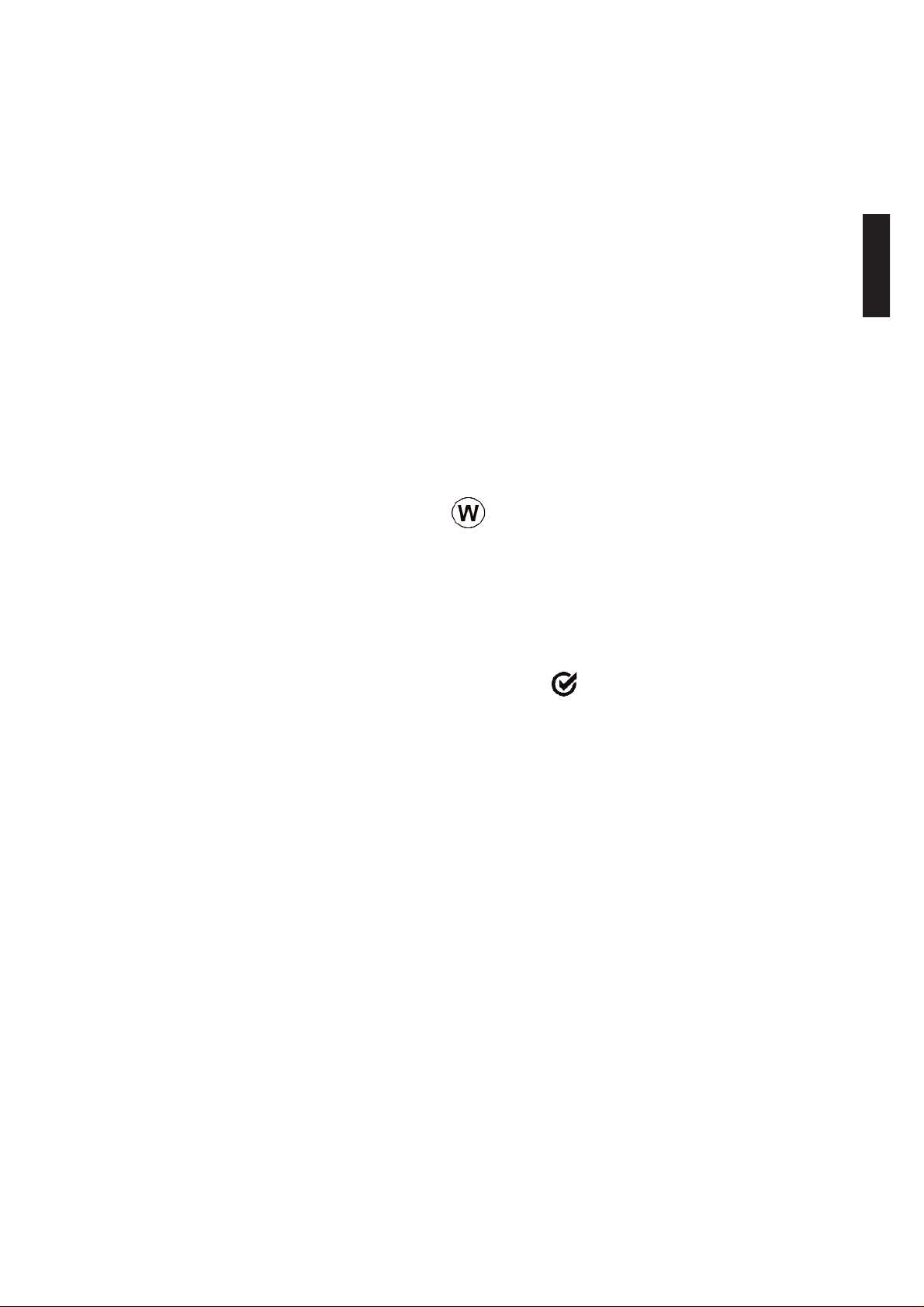
Displays
3
Solid indicates good
wireless connection to
probe. Flashing
indicates no probe
connection.
Base Unit Display:
Last
Measurement
Current Calibration
Setting
Unit of
Measurement
Maximum Amplitude Dot
Probe Display (button not pressed):
Amplitude Indicator
Results Indicator
Distance Target Bar
Probe Batteries Status (pg. 15)
Bluetooth Function Indicator
Predicted Cured Thickness Result
Distance Paddle
Predicted Cured
Thickness Result
Probe Display (button pressed):
Factory Calibration
Symbol (pg. 8)
Page 5

Bluetooth Function Indicator: The symbol indicates the base unit
and wireless probe are communicating properly.
Results Indicator: When the probe is in the proper position and good
samples are being taken, a solid DOT blinks on the probe display, the
base unit LED blinks green and emits a high beep. When samples are
inconclusive, an "X" blinks on the probe display, the base unit LED
blinks red and emits a low beep.
Distance Paddle: Graphically represents the distance to the target. It
rises and falls to indicate distance from the probe tip to the surface of
the powder.
Distance Target Bar: The optimum distance for measurement is 18
mm (3/4 inch) between the tip of the probe and the surface of the
applied powder. During measurement, keep the Distance Paddle close
to the Distance Target Bar.
Amplitude Indicator: Strength of the ultrasonic echo. A high position
indicates good probe orientation relative to perpendicular. The bar will
generally reach higher positions when measuring thin powder and when
the probe is at a 90-degree angle to the powder surface.
Maximum Amplitude Dot: Marks the highest position the Amplitude
Indicator reached during the current measurement attempt.
Predicted Cured Thickness Result: When a valid measurement is
calculated, the base unit BEEPS twice, the LED blinks green, and the
predicted cured measurement result is displayed on both the probe and
base unit. Continuing to hold the probe button will result in additional
samples being taken.
There are 4 types of displayed measurement results:
43 — Predicted thickness result.
0 — The collected samples have resulted in a good reading, but the
resultant predicted cured thickness is less than the minimum range.
++ — The collected samples have resulted in a good reading, but the
resultant predicted cured thickness is greater than the maximum range.
- - — An indeterminate or invalid reading.
4
Page 6
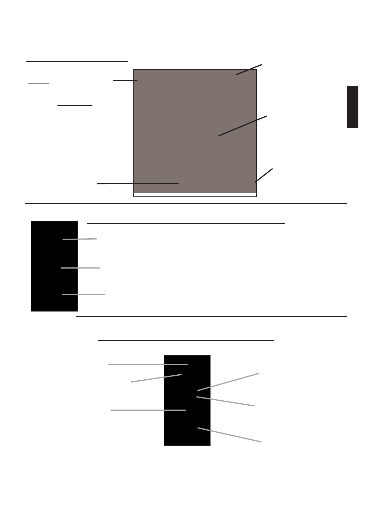
Menu Operation
Instrument functions on the base unit are menu controlled. To access
the full Menu, power-up both the probe and base unit. Then press the
(.:::.button. If the probe is not powered-up a condensed menu is
displayed.
5
Reset
Flip Display
Gage Info
Units
Set Clock
Language
USB Drive
Exit
Memory
Statistics*
Zero*
Cal Settings
Setup
Exit
* Appears when probe is ON
Current selection is displayed
with darkened background
To navigate, press (-) to scroll DOWN, (+) to scroll UP and (.:::.) to
SELECT. To exit any menu, press both (-) and (+) buttons
simultaneously or select Exit from the Menu.
List boxes have a down arrow on the right-hand side. Use the (-) or (+)
buttons until your desired choice appears, then press (.:::.) to select this
choice and move focus onto the next item.
A "tick" indicates this square
box has been selected
“List” box
Page 7

6
Verification of Accuracy
Before first use on a new powder and periodically thereafter, the user
should perform an accuracy check. This ensures the gage is working
properly by comparing predicted thickness values with actual cured
thickness values.
1. Zero the probe (pg. 6).
2. Electrostatically spray powder onto a flat, smooth metal sample.
3. Measure the uncured powder with the PosiTector PC.
4. Cure the powder.
5. Measure cured thickness with a magnetic or eddy current coating
thickness gage such as the PosiTector 6000. Compare results.
A successful verification requires that the average of a series of
measurements by both instruments be within their combined tolerances.
If not, adjust the PosiTector PC using one of the methods described on
page 8.
For best accuracy, perform a Zero at the beginning of every shift to
compensate for temperature and humidity changes. It is also required
after a Reset (pg. 13).
Zero Menu Option
1. Place the included Powder Probe Fixture onto a hard, flat,
smooth surface (i.e. glass or metal).
2. Place the measuring end of the probe into the Fixture.
3. Power-up both units.
4. On the base unit select the Zero
menu option. The zero process
can take up to 30 seconds.
Zero
Page 8

7
Calibration and Adjustment
The PosiTector PC is factory calibrated and performs an automatic
self-check each time it calculates a measurement. For many powder
measurement applications no further adjustment is necessary. Simply
Zero at the beginning of each shift, then measure.
Sometimes gage measurement calculations can be influenced by the
composition of the coating powder. A calibration adjustment improves
accuracy in these circumstances.
Adjustment, or Calibration Adjustment, is the act of aligning the gage's
predictions to match those of a known cured sample.
Begin by performing a Verification of Accuracy (pg. 6) to determine if
there is a need for an adjustment. If the average of several thickness
results is outside the combined tolerances of the two measuring
instruments (PosiTector PC and dry film thickness instrument) then 3
adjustment techniques are available to correct the variance.
User adjustments are stored in the current Cal setting. It may be
desirable to open a new Cal setting first (pg. 10).
Cal Settings
CAL
Cal Memory
1 Pt Adjust*
2 Pt Adjust*
Powder Comp*
Exit
* These menu options
appear only when the
probe is powered-up.
Page 9

8
Factory Calibration Symbol
This symbol indicates the instrument is measuring with factory
calibration settings. It appears whenever a Reset (pg. 13) is
performed or whenever a new calibration setting (pg. 10) is
created. It disappears whenever a calibration adjustment is made (pg.
8) or when a user calibration is loaded from cal memory (pg. 10). A
probe Zero (pg. 6) does not change the status of the symbol.
Adjustment Techniques
To ensure the gage is working properly, the user should periodically
perform an accuracy check by comparing predicted thickness values
with actual cured thickness values (pg. 6).
If the average of a series of measurements by both instruments is not
within combined tolerances, the PosiTector PC can be adjusted using
one of three methods.
1) 1-point Adjustment - The first and most common choice.
2) 2-point Adjustment - If a 1 Pt Adjust does not improve accuracy.
3) Powder Compensation - If adjustments fail to improve accuracy.
1. Zero the probe (pg. 6).
2. Electrostatically spray approximately 75 microns (3 mils) of powder
onto a flat, smooth metal sample.
3. Open a New CAL setting (optional - pg. 10).
4. Select New Batch (pg. 11).
5. Take at least 3 uncured powder measurements with the PosiTector
PC. Results will be stored in the Batch.
6. Cure the powder.
7. Measure cured thickness with a magnetic or eddy current coating
thickness gage. Record the results.
8. Select "1 Pt Adjust" then select the batch name from Step 4 into
which the previous measurements had been placed.
9. Adjust the displayed batch average lower (-) or higher (+) to match
the cured thickness value.
1 Pt Adjust
Page 10

9
1. Zero the probe (pg. 6).
2. Electrostatically spray powder onto 2 flat, smooth metal samples.
Place approximately 40 microns (1.5 mils) on one and 75 microns
(3 mils) on the other.
3. Open a New CAL setting (optional - pg. 10).
4. Select New Batch (pg. 11)
5. Take at least 3 uncured powder measurements on the thin powder
panel with the PosiTector PC. Results will be stored in the Batch.
6. Open a second new Batch.
7. Take at least 3 uncured powder measurements on the thick powder
panel with the PosiTector PC. Results will be stored in the
second Batch.
8. Cure the powder on both panels.
9. Measure cured thickness with a magnetic or eddy current coating
thickness gage. Record the results.
10. Select "2 Pt Adjust" then select the appropriate batch names
when asked.
11. Adjust the displayed batch averages lower (-) or higher (+) to match
the cured thickness values.
1. Zero the probe (pg. 6).
2. Electrostatically spray a thick layer of powder (135 microns / 5 mils)
onto a flat, smooth metal sample. Lay the panel on a table surface.
3. Place the included Powder Probe Fixture onto the coated panel.
4. Place the measuring end of the probe into the Fixture.
5. On the base unit select the "Powder Comp" menu option. This can
take up to 30 seconds.
6. A 1- or 2-point adjustment may be required after this operation.
2 Pt Adjust
Powder Comp
Note: The symbol on the display will turn off after
the successful completion of an adjustment.
Page 11

10
Calibration Memory
When measuring a particular part with a specific powder, it is often
convenient to be able to store any unique calibration adjustments made
for that application. Then, if you return to that part, the corresponding
Cal setting can be conveniently and quickly restored.
A Cal setting is any of the three calibration adjustments (pg. 8). The
PosiTector PC always displays the current calibration setting (ex. Cal
3) in the upper right corner of the display.
The gage reverts back to its factory default Cal 1 setting after a Reset
(pg. 13) or if the user deletes all calibration settings (below).
-Creates a new calibration setting using the next available number
(Maximum of 9). By default, these new Cal settings are initially created
with the gage's factory settings as indicated with the symbol that
appears at the bottom of the display.
-Loads an existing calibration setting. Use the (-) or (+) buttons to scroll
the List box until the desired setting appears, then press
(.:::..
-Removes a calibration setting completely from the list. That Cal
number can be reused later with the "New" command.
-Sends a list of all Calibration Settings to the IR printer using the gage's
built-in IR port.
Cal Memory
New
Open
Delete
Print
Page 12

11
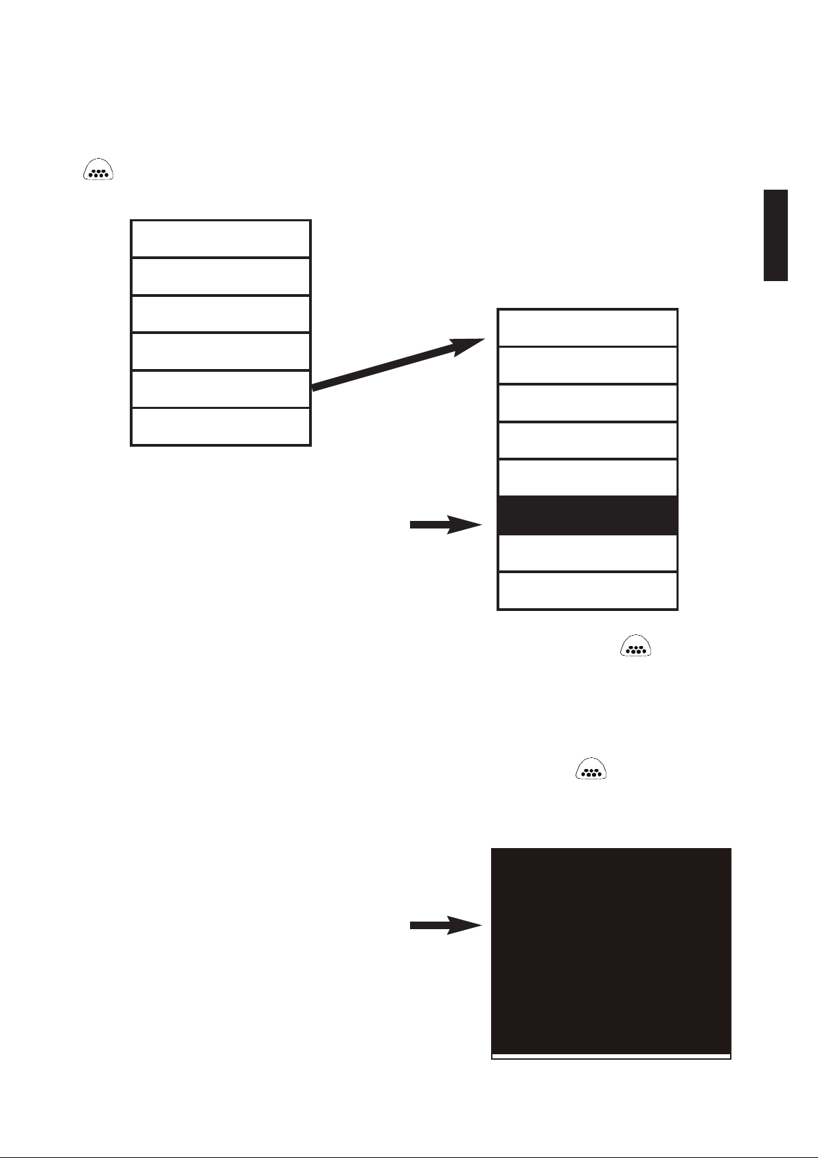
Memory Mode
The PosiTector PC can record 1,000 measurements in up to 100
groups (batches) for on-screen statistical purposes, for printing to an
optional IR printer, or for downloading to a computer using the included
USB cable. Readings are time-stamped as they are taken.
(This menu option appears only when the probe is powered-up)
-Closes any currently opened batch and creates a new batch name
using the next higher number. For example, if only Batch 1 and Batch
3 exist, then Batch 4 would be created and made the current batch.
S
tatistics are displayed and each measurement will now be
simultaneously shown on the display and stored into this new batch.
On-screen statistics are immediately updated with each measurement.
New batch names are date stamped at the time they are created.
Opening a New Batch will turn Statistics mode OFF.
Shortcuts: When a batch is open, create a new batch by pressing (+).
Remove the last reading from the current open batch by pressing (-).
Memory
New Batch
Mean (average)
Max and Min
measurement
Current Batch
No. of
measurements
Last reading
Standard Deviation
Open
-Selects a previously created batch to open and makes current. If it
contains measurements, on-screen statistics will immediately reflect
values calculated from this batch. Opening an existing Batch will turn
Statistics mode OFF.
Page 13

12
-Stops the recording process, closes the current batch, and removes
the statistics from the display.
-Removes the selected batch completely from memory. The name is
deleted and all measurements are erased.
-Lists all readings on the display from the currently selected batch. The
last batch is viewed if no batch is currently open. Upon selection, the
last 10 measurement values are initially shown. Scroll using the (-) or
(+) buttons. Hold for 1 second to scroll a page at a time.
-Prints all stored measurements from the selected batch, or all batches,
to the optional IR printer. Press both (-) and (+) buttons simultaneously
to cancel printing.
Downloading Measurement
s
A computer can view and download measurements stored in memory
using the included USB cable. Measurements are not erased from
memory after downloading. See "USB Drive" on pg. 14.
Statistics Mode
The PosiTector PC can display basic statistical
information as measurements are taken. Individual
measurement results are not stored into memory.
When Statistics is selected, a symbol and a
statistical summary appear on the display.
Notes:
Remove the last measurement by pressing the (-) button.
Clear statistics by pressing the (+) button.
Turning Statistics mode ON will close a currently open batch.
Turning Statistics mode OFF will clear all current statistical information.
Close
Delete
View
Print
Statistics
Page 14
13
Setup Menu
Reset restores factory settings and returns the gage to a known, out-of-
the-box condition. It is handy when you want to "start all over".
The following occurs:
- All batches are closed and stored measurements are erased.
- Calibration adjustments are cleared and the instrument is returned to
the gage's factory calibration settings as CAL 1.
- Menu settings are returned to the following:
Memory = OFF
Statistics = OFF
USB Drive = ON
A more thorough Reset can be performed by holding the (+) button
when the gage is powered down until the Reset symbol appears. It
performs the same function as a menu Reset with the addition of Units
= microns, Language = English, and Flip Display = Normal.
A probe Zero (pg. 6) must be performed after any Reset.
This option causes the base unit display to read upside down. Ideal for
viewing while the base unit is attached to a waist belt so that the display
is conveniently pointed toward the operator.
This menu button converts the display and all stored readings from
microns to mils or vice versa.
All batches are date-stamped when created and all measurements are
time-stamped (24 hour format) when stored into these batches. It is
therefore important to keep both the date and time current using this
menu option.
Setup
Reset
Set Clock
Units
Flip Display
Page 15

14
USB Drive - Selected
The PosiTector PC uses a USB mass storage device class which
provides a simple interface to retrieve data in a manner similar to USB
flash drives, cameras, or digital audio players.
When the "USB Drive" option is selected with a tick mark , any
computer can view and download measurements stored in memory (in
batches) by navigating a virtual drive labeled POWDER using the
included USB cable.
USB Drive
A formatted HTML report is viewed by selecting the "index.html" file
found in the root directory. Optionally, "readings0.txt" files located in
each batch folder (i.e. B1) provide access to measurement values.
New drive
Measurement values,
reports, graphs, or the
entire POWDER virtual
drive can be copied onto
your computer or imported
into a document or
spreadsheet for permanent
storage. The "logo.jpg" file
can be replaced with a
corporate logo.
While the USB cable is connected to a computer, new measurements
will not be included in reports and text files until the USB cable is
unplugged and re-connected.
ü
Page 16

15
USB Drive - Un-Selected
When this option is not selected with a tick mark , measurement
values can be downloaded, as they are taken, to a computer, data
collector, or powder controller using a serial gadget driver.
Note: When the USB Drive option is changed (selected or de-selected),
the instrument must be powered-down, then powered-up to undertake
the change.
Note: When a USB cable is connected to the base unit, power is
supplied through the USB cable. The batteries are not used and the
base unit will not automatically power down.
Maintenance
The base unit requires no maintenance except battery replacement.
Clean with a soft brush or cloth.
The screen at the measuring end of the probe can be unscrewed for
cleaning. Accumulated powder should be carefully removed from the
screen by no more than 0.2 MPa (20 - 30 psi) of compressed air. Do
not direct air directly into the probe. Replacement screens are available.
Changing the Batteries
The battery symbol displays a full bar with
fresh alkaline batteries installed. As the batteries
weaken, the bar will be reduced. When the
battery symbol is low the gage can still be
used, but the batteries should be changed at the
earliest opportunity. Use only "AAA" alkaline
batteries (3) in the base unit and "AA" alkaline
batteries (3) in the probe. Nickel-cadmium and
nickel-metal hydride rechargeable batteries will
work but the gage may appear to have weak batteries. The gage will
turn off automatically when batteries are very low, preceded by a low
battery warning on the display. If batteries are very low the gage may
startup but then turn off quickly.
Note: To retain all user settings and stored memory readings, only
replace the batteries after the gage has automatically powered-down.
Page 17

16
Returning for Service
Before returning the instrument for service…
1. Install new alkaline batteries in the proper alignment shown within
battery compartments.
2. Examine the probe screen for dirt or damage.
3. Perform a Reset (pg. 13) and a Zero (pg. 6)
If you must return the instrument for service, describe the problem fully
and include measurement results, if any. Be sure to also include the
base unit, probe, your company name, company contact, telephone
number and fax number or email address. Return to your point of
purchase.
Website: www.defelsko.com/support
Technical Data
Conforms to ASTM D7378
Base unit dimensions: 146 x 64 x 31 mm (5.75" x 2.5" x 1.2")
Probe dimensions: 222 x 50mm diameter (8.75" x 2" diameter)
Alkaline Batteries: Base unit 3 "AAA" batteries. Probe 3 "AA" batteries
Temperature Range: 0 to 40°C (+32° to +104°F)
Measuring Range: 20 - 110 microns (0.8 - 4.3 mils)
Measuring Resolution: 1 micron (0.05 mil)
Measuring Distance: approximately 18 mm (3/4 inch)
Measurement Area: 2 mm (0.08 inch)
Measuring Time: approximately 2 to 5 seconds
Accuracy: ±5 microns (± 0.2 mils)
The probe uses ultrasound frequencies above 100KHz with sound
pressure levels well below 110 dB (relative to 20uPa).
Available Options
A variety of accessories are available to help you get the most from
your PosiTector PC Powder Checker.
Page 18

17
Limited Warranty, Sole Remedy and Limited Liability
DeFelsko's sole warranty, remedy, and liability are the express limited
warranty, remedy, and limited liability that are set forth on its website:
www.defelsko.com/terms
Warning: The PosiTector PC Powder Checker contains a
very powerful magnetic mount for attaching the protective
rubber holster to nearby steel structures. As with all magnets,
avoid contact with electronic instruments or devices sensitive to
magnetic fields such as pace makers and coating thickness
gages. Care should also be given to the storing and shipping of
any strong magnet to prevent contact with sensitive devices.
Page 19

Page 20

 Loading...