

Page 1

Barcol Hardness Impressor
Quick Guide v.1.0
Find Quality Products Online at: sales@GlobalTestSupply.com
www.GlobalTestSupply.com
Page 2
Introduction
Introduction
The PosiTector Barcol Hardness Impressor (BHI) is a hand-held
electronic instrument that measures the indentation hardness of soft
metals (aluminum, copper, brass), harder plastics and fiberglass. It
consists of a PosiTector body (Standard or Advanced) and an
interchangeable probe.
This Quick Guide summarizes the basic functions of the gage.
Quick Start
Quick Start
The PosiTector BHI powers-up when the center navigation
button is pressed. To preserve battery life, the Gage powers-down
after approximately 5 minutes of no activity. All settings are retained.
1. Power-up the Gage by pressing the center navigation button.
Ensure the probe indentor (pg. 2) is not in contact with any
surface.
2. To take a measurement:
a) Ensure the probe is perpendicular to the surface being tested.
Press the probe down onto the material to be measured until the
indentor foot is in full, flat contact with the surface. HOLD STEADY
against the surface.
b) The Gage will emit a single BEEP and display a ▼ symbol
indicating a reading is being taken. The test timer will begin
counting down (see Test Time, pg. 7). When the timer reaches 0s,
the Gage will BEEP twice and display the measurement value.
3. Lift the probe from the surface between readings.
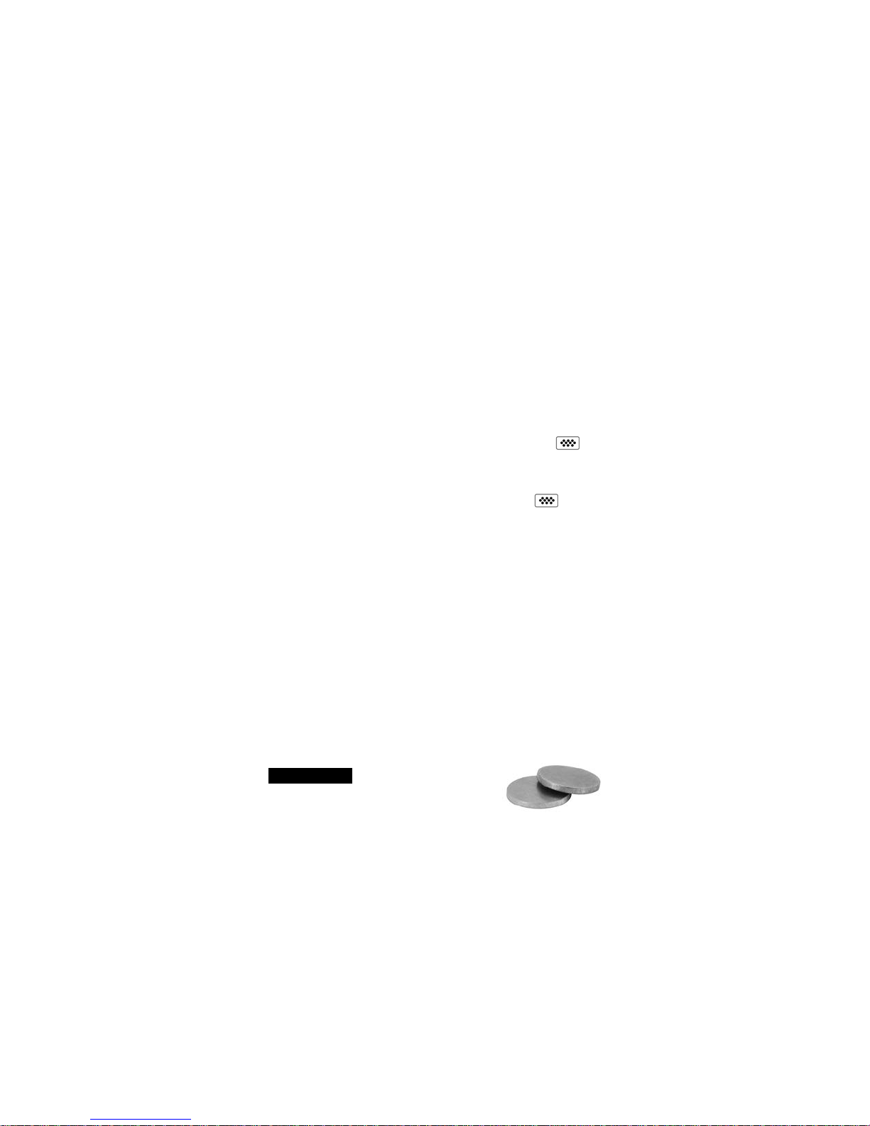
Verify accuracy (pg. 3) on test disks at the beginning and the end of
each shift, or if the gage is dropped or suspected of giving erroneous
readings. Be sure to place the leg on the included leveling plate when
testing disks to maintain perpendicularity.
IMPORTANT:
when they become worn or visibly pitted.
Test disks should be replaced
1
Find Quality Products Online at: sales@GlobalTestSupply.com
www.GlobalTestSupply.com
Page 3
Menu Operation
Menu Operation
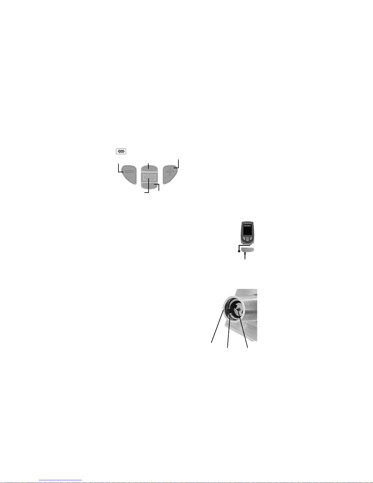
Gage functions are menu controlled. To access the Menu, power-up
the gage, then press the center navigation button.
To navigate, use the Up and Down buttons to scroll vertically and
to SELECT.
Previous Page
(Exit)
Access the Menu
(Center/Select)
When powered-up, the PosiTector automatically determines which
probe is attached and does a self-check.
To disconnect a probe from a body, slide the plastic probe
connector horizontally (in the direction of the arrow) away
from the body. Reverse these steps to attach a different
probe. It is not necessary to power-down the Gage when
switching probes.
The PosiTector gage body accepts a wide variety of probe
types including magnetic, eddy-current and ultrasonic coating
thickness, surface profile, environmental, hardness, salt
contamination and ultrasonic wall thickness probes.
Next Page
Up
Down
Press the (+) button to switch
pages in a multipage menu.
Press the (-) button to return to
the previous menu or page.
Select Exit to exit from any
menu.
Probes
Probes
The PosiTector BHI consists of the PosiTector
BHI probe, Standard or
leveling plate, test disks (2), replacement indentor,
replacement indentor tool, glass plate, calibration
certificate, protective rubber holster with belt clip,
wrist strap, 3 AAA alkaline batteries, instructions,
protective lens shield, convenient hard shell
carrying case, USB cable, PosiSoft Software, and
two (2) year warranty.
Advanced gage body,
Sleeve
2
Indentor Foot
Indentor
Find Quality Products Online at: sales@GlobalTestSupply.com
www.GlobalTestSupply.com
Page 4
Calibration, Verification and Adjustment
Calibration, Verification and Adjustment
Three steps ensure best accuracy…
1. Calibration - typically performed by the manufacturer. All probes
include a Certificate of Calibration.
2. Verification of Accuracy - typically performed by the user on
known reference standards such as the included test disk.
3. Adjustment - to a known hardness
Calibration
Calibration is the high-level, controlled and documented process of
measuring traceable calibration standards over the full operating
range of the probe, and verifying that the results are within the stated
accuracy of the probe. Calibrations are performed by the
manufacturer, their authorized agent, or by an accredited calibration
laboratory in a controlled environment using a documented process.
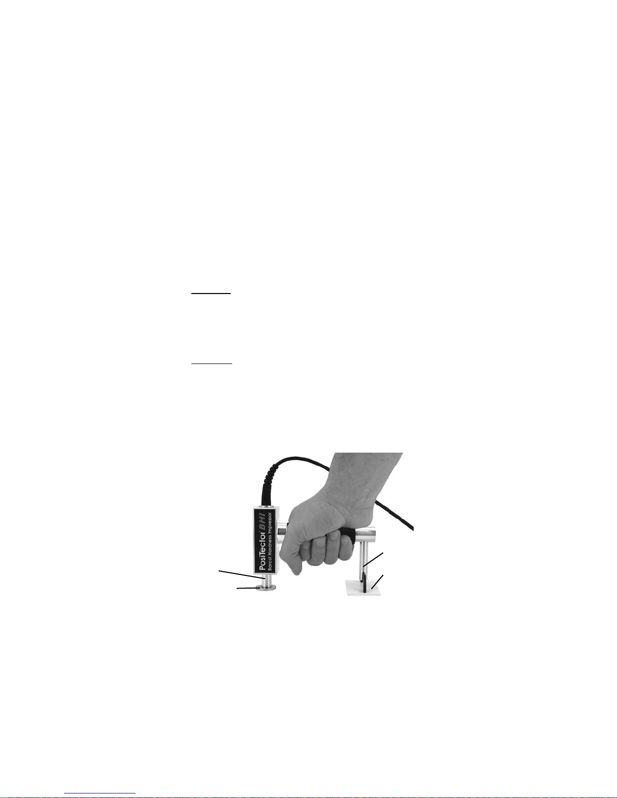
Verification
Verification is an accuracy check performed by the user on known
reference standards. A successful verification requires the Gage to
read within the combined accuracy of the probe and the Test Disks.
Instrument operation may be verified with the included Test Disks and
Leveling Plate. Position the Leveling Plate under the Leg and place the
Test Disks on a flat, hard surface (as shown). Take three to five
readings on each disk. The measurement points should be at least
6mm (0.24”) apart. If the average of those readings is outside the
combined accuracy of the Test Disk and gage, service may be
required.
Leg
Sleeve
Test Disk
Leveling
Plate
3
Find Quality Products Online at: sales@GlobalTestSupply.com
www.GlobalTestSupply.com
Page 5

Some causes for the gage to not read properly are the indentor being
damaged, incorrect pressure being applied to the test disk or
temperatures beyond normal conditions.
Verify accuracy at the beginning and the end of each work shift. During
the work shift, if the Gage is dropped or suspected of giving erroneous
readings, its accuracy should be re-verified.
Adjustment
Adjustment, or Calibration Adjustment, is the act of aligning the Gage’s
readings to match that of a known reference in order to improve
accuracy of a gage on a specific material. (see Cal Settings, pg. 4)
Cal Settings Menu
Cal Settings Menu
The PosiTector BHI is factory calibrated and for most applications
no calibration adjustment is required. However, there may be times
when a zero, one or two point adjustment is necessary including
after indentor replacement or to compensate for indentor wear.
Zero
Zeroing the Gage may be necessary after indentor replacement
or when the indentor is worn. For best accuracy, the Gage
should be zeroed on the included glass plate.
1. Select from the menu.
2. Press the (+) button to select the number of readings
3. Measure on the glass plate, ensuring that both the indentor
foot and leg are resting on the glass plate. After the last
measurement, the Gage will calculate a Zero which
represents the average of all the Zero readings taken.
Zero
4
Find Quality Products Online at: sales@GlobalTestSupply.com
www.GlobalTestSupply.com
Page 6

1 Pt Adjust
Adjusts the Gage to a known material hardness.
Step 1: Select 1 Pt Adjust from the Cal Settings menu.
Step 2: Press the (+) button to select the number of readings to
be used to obtain an average, typically 3 to 10 readings. The
greater the variation between readings, the more readings should
be taken to obtain an average.
Step 3: Repeatedly measure the known hardness sample using
the on-screen green arrows as a guide. After the final reading,
the Gage will calculate and display an average measurement
value of all readings taken on the sample. If the expected
hardness value is not obtained (within tolerance), adjust the
displayed value up (+) or down (-) to the known hardness value
and press to save the value.
2 Pt Adjust
Adjusts the Gage within a range of two material hardnesses.
Step 1: Select 2 Pt Adjust from the Cal Settings menu.
Step 2: Press the (+) button to select the number of readings to
be used to obtain an average for the first point, typically 3 to 10
readings.
Step 3: Repeatedly measure the known hardness sample using
the on-screen green arrows as a guide. After the final reading,
the Gage will calculate and display an average measurement
value of all readings taken on the sample.
Step 4: Repeat Step 2 and 3 for second point.
5
Find Quality Products Online at: sales@GlobalTestSupply.com
www.GlobalTestSupply.com
Page 7

Setup Menu
Setup Menu
Reset
Reset (menu reset) restores factory settings and returns the
Gage to a known condition. The following occurs:
- All batches, stored measurements, batch names and screen
captures are erased.
- Calibration adjustments are returned to factory settings.
- Menu settings are returned to the following:
Memory = OFF
Auto Sub-Batch = OFF
Statistics = OFF
Hi Lo Alarm = OFF
Perform a more thorough Hard Reset as follows:
1. Power down the Gage and wait 5 seconds.
2. Simultaneously press and hold the (+) and center buttons
until the Reset symbol appears.
This returns the Gage to a known, “out-of-the-box” condition.
It performs the same function as a menu Reset with the addition of:
- Bluetooth Pairing info is cleared.
- Menu settings are returned to the following status:
Bluetooth Smart = OFF
Test Time = 1 second
Sound = ON
Backlight = Normal
Flip Display = Normal
Bluetooth & Stream = OFF
WiFi & Access Point = OFF
Auto Dim = ON
Hi Res = OFF
Auto Sync .net = ON
USB Drive= ON
Language = English
Battery Type = Alkaline
NOTE:
Date, Time and WiFi settings are not affected by either Reset.
6
Find Quality Products Online at: sales@GlobalTestSupply.com
www.GlobalTestSupply.com
Page 8

Test Time
The PosiTector BHI has an on-screen timer to measure the
hardness of a material after a given period of time.
Use the (-) and (+) buttons to adjust the test duration. When
taking a reading, the timer starts automatically once the indentor
is on the surface and the ▼ symbol appears on the display.
Hi Res
Increases the displayed resolution. Accuracy is not affected.
Cont. Reading
When enabled, the Gage will continuously display probe readings.
Ideal when a test timer is not required or when performing a
calibration verification. Cont. Reading is not available when
Memory, Statistics or HiLo Alarm modes are enabled.
Battery Type
Selects the type of batteries used in the Gage from a choice of
“Alkaline”, “Lithium” or “NiMH” (nickel-metal hydride
rechargeable). If “NiMH” is selected, the Gage will trickle charge
the batteries while connected via USB to a PC or optional AC
power supply (USBAC). The battery state indicator symbol is
calibrated for the selected battery type. No damage will occur if the
battery type used in the Gage does not match the selected battery
type.
Statistics
A statistical summary will appear on the display. Remove the last
reading by pressing the (-) button. Press (+) to clear statistics.
Average
Maximum Value
HiLo Alarm
Allows Gage to visibly and audibly alert the user when readings
exceed user-specified limits.
(Continuous Reading)
Statistics Mode
Statistics Mode
Standard Deviation
Minimum Value
7
Find Quality Products Online at: sales@GlobalTestSupply.com
www.GlobalTestSupply.com
Page 9

Memory Management
Memory Management
The PosiTector BHI has internal memory storage for recording
measurement data. Stored measurements can be reviewed onscreen or accessed via computers, tablets and smart phones. All
stored measurements are date and time-stamped.
The symbol appears when the Gage is set to store measurement
data.
Standard models store up to 250 readings in one batch.
Advanced models store 100,000 readings in up to 1,000
batches. “New Batch” closes any currently opened batch and
creates a new batch name using the lowest available number.
New batch names are date-stamped when they are created.
Screen Capture
Press both the (-) and (+) buttons at any time to capture and save
an image copy of the current display. The last 10 screen captures
are stored in memory and can be accessed when connected to a
computer (see PosiSoft USB Drive
Auto Sub-Batch
This option will automatically create a new sub-batch after the
required number of readings are stored in the current sub-batch.
Use the (-) and (+) buttons to set the number of readings to store
in each sub-batch, then select New to open the first sub-batch.
(Advanced models only)
, pg. 9).
8
Find Quality Products Online at: sales@GlobalTestSupply.com
www.GlobalTestSupply.com
Page 10

Maintenance
Maintenance
The PosiTector BHI includes an
indentor tip precisely machined with a
26° angled tip. Visually inspect the tip
for damage at the beginning of each
work shift or if the gage is dropped or
suspected of giving erroneous
readings
If the indentor becomes worn or damaged, a replacement indentor
is included. Using the enclosed indentor replacement tool,
unscrew the damaged indentor and replace. Tighten the new
indentor and verify gage operation (pg. 3) before testing. A ZERO,
1 Pt or 2 Pt Cal Adjust may be required (pg. 5).
Accessing Stored Measurement Data
Accessing Stored Measurement Data
DeFelsko offers the following free solutions for viewing, analyzing
and reporting data:
PosiSoft USB Drive - Connect the Gage to a PC/Mac using the
supplied USB cable. View and print readings and graphs using
universal PC/Mac web browsers or file explorers. No software or
internet connection required. USB Drive must be selected in the
Gage’s “Connect > USB” menu (pg. 10).
PosiSoft Desktop - Powerful desktop software (PC/Mac) for
downloading, viewing, printing and storing measurement data.
Includes a customizable, templated PDF Report Generator. No
internet connection required.
PosiSoft.net - Web-based application offering secure, centralized
storage of measurement data. Access your data from any webconnected device.
PosiTector App - (
App for compatible iOS and Android smart devices. Permits users
to create, save and share professional PDF reports. Add images
and notes using the smart device’s camera and keyboard.
Advanced models only, serial numbers 784000+)
Indentor and Replacement Tool
9
Find Quality Products Online at: sales@GlobalTestSupply.com
www.GlobalTestSupply.com
Page 11

Connect Menu
WiFi
Allows connection to your local wireless network or mobile
hot spot. Ideal for using your network’s internet connection for
synchronizing stored measurements with PosiSoft.net (pg. 9).
USB
When USB Drive is checked , the PosiTector gage uses
a USB mass storage device class which provides users with a
simple interface to retrieve stored data in a manner similar to
USB flash drives, digital cameras and digital audio players.
USB Drive is also required to import stored measurements into
PosiSoft Desktop software (pg. 9).
NOTE:
USB cable. The batteries are not used and the body will not
automatically power down. If rechargeable (NiMH) batteries
are installed, the instrument will trickle charge the batteries.
Stream individual readings to a USB connected computer via a
serial protocol. Ideal for use with serial compatible SPC data
collection software.
The above WiFi, USB and Bluetooth menus contain a Sync .net
Now option. When selected, the Gage immediately synchronizes
stored measurement data via its respective communication
method (internet connection required). Alternatively, select Auto
Sync .net from within the USB connect menu to automatically
synchroniz e upon connection to a PC. Additional measurements
added to memory while connected are synchronized only when
the USB cable is disconnected and reconnected, or when the
Sync.net Now option is selected. WiFi connected gages
automatically attempt synchronization upon power-up.
When connected, power is supplied through the
Stream
NOTE:
Sync .net Now
(Advanced models only)
(Advanced models only,
serial numbers 784000 and greater)
For more information on USB Keyboard and Streaming
10
Find Quality Products Online at: sales@GlobalTestSupply.com
www.GlobalTestSupply.com
Page 12

NOTE:
connections to synchronize measurements with PosiSoft.net.
PosiSoft Desktop is required when using USB
Bluetooth
Allows individual readings to be sent to a computer, printer or
compatible device as they are taken using Bluetooth wireless
technology.
Bluetooth Smart
When Enabled , allows communication with a smart device
running the PosiTector App (pg. 9) via auto-pairing Bluetooth
Smart (BLE) wireless technology.
Sync Batches
Select batches to flag them for synchronization to the
PosiTector App. New batches created while Bluetooth Smart
is enabled are automatically selected.
With Bluetooth Smart enabled, select Sync Batches to transfer
selected batches to the PosiTector App. This is useful when
switching between smart devices, as only readings and batches
that have yet to be synchronized with any smart device are
synchronized automatically.
NOTE:
selected in the Sync Batches menu are held in a queue until
communication with the PosiTector App is re-established.
Transfers selected batches to the PosiTector App (useful
when switching between devices).
The Send Batches option is visible in the menu when the Gage
is connected to a smart device running the PosiTector App.
Determine if a software update is available for your Gage.
If Bluetooth Smart is disabled, data from batches
Send Batches
Updates
(Advanced models only)
(Advanced models only,
serial numbers 784000 and greater)
WARNING:
an update. All stored measurements will be erased from memory.
The Gage will perform a Hard Reset (pg. 6) after
11
Find Quality Products Online at: sales@GlobalTestSupply.com
www.GlobalTestSupply.com
Page 13

Returning for Service
Returning for Service
Before returning the Gage for service…
1.Install new or newly recharged batteries in the proper
alignment as shown within battery compartment.
2.Examine the indentor tip and indentor foot for dirt or damage.
3.Perform a Hard Reset. (pg. 6)
4.Attempt a measurement on the supplied test disk.
(see Verification, pg. 3)
5. If issue is not resolved, Update your PosiTector gage body
(pg. 11) and re-attempt measurements.
IMPORTANT:
If you must return the Gage for service, please fill out and
include the Service Form
with the Gage. Be sure to also include the probe, your company
name, company contact, telephone number and fax number or
email address.
Limited Warranty, Sole Remedy
Limited Warranty, Sole Remedy
and Limited Liability
and Limited Liability
DeFelsko's sole warranty, remedy, and liability are the express
limited warranty, remedy, and limited liability
© DeFelsko Corporation USA 2018
This manual is copyrighted with all rights reserved and may not be reproduced or transmitted, in whole
or part, by any means, without written permission from DeFelsko Corporation.
DeFelsko, PosiTector and PosiSoft are trademarks of DeFelsko Corporation registered in the U.S. and
in other countries. Other brand or product names are trademarks or registered trademarks of their
respective holders.
Every effort has been made to ensure that the information in this manual is accurate. DeFelsko is not
responsible for printing or clerical errors.
All Rights Reserved
12
Find Quality Products Online at: sales@GlobalTestSupply.com
www.GlobalTestSupply.com
 Loading...