

Page 1
Model 100 Series
Ultrasonic Multi-layer
Coating Thickness Gage
Instruction Manual
version 4.0
Page 2

Page 2 100 Series
Page 3

DeFelsko Corporation USA 1999
All Rights Reserved • Patents applied for • Printed in U.S.A.
This manual is copyrighted with all rights reserved and may not be reproduced
or transmitted, in whole or part, by any means, without written permission from
DeFelsko Corporation.
DeFelsko, PosiTector and PosiSoft are
trademarks of DeFelsko Corporation registered
in the U.S. and in other countries. Microsoft.
Windows NT, Windows 95 and Windows 98 are
registered trademarks of Microsoft Corporation.
HP is a registered trademark of Hewlett-Packard
Corporation. Other brand or product names are
trademarks or registered trademarks of their
respective holders.
Every effort has been made to ensure that the information in this manual is
accurate. DeFelsko is not responsible for printing or clerical errors.
01/99
Multi-layer Model 100
••standard •• memory
Gage Serial Number: ______________
Probe (B, C or D): _________________
Probe Serial Number: ______________
Date Purchased: __________________
100 Series Page 3
Page 4

SAFETY, CARE AND MAINTENANCE......................................................................6
QUICK START ......................................................................................................7
PHYSICAL OVERVIEW ..........................................................................................8
Packing List ....................................................................................................8
Gage Description ............................................................................................8
Available Probes............................................................................................. 9
LCD DISPLAY ...................................................................................................10
Status Bar .....................................................................................................10
Menu Bar...................................................................................................... 10
Measurements Area.......................................................................................11
Graphics.......................................................................................................11
Statistics........................................................................................................ 12
Memory......................................................................................................... 13
Sets...............................................................................................................13
OPERATION OVERVIEW...................................................................................... 14
Theory of Operation......................................................................................16
Couplant.......................................................................................................17
Power-up / Power-down................................................................................17
How to take a measurement........................................................................... 18
APPLICATIONS...................................................................................................19
Select an Existing Application........................................................................20
Edit Application Settings ...............................................................................20
Create a New Application ..............................................................................20
Delete an Existing Application....................................................................... 20
RECORDING AND DOWNLOADING MEASUREMENTS............................................. 21
Creating Batches...........................................................................................21
Annotating Batches........................................................................................21
Viewing and Editing Batches.........................................................................22
Charting Batches........................................................................................... 23
Printing......................................................................................................... 23
CALIBRATION AND OPTIMIZATION......................................................................24
Overview.......................................................................................................24
Calibration.................................................................................................... 25
Effects of Temperature.......................................................................................... 25
Calibration Interval ............................................................................................... 26
Optimization .................................................................................................26
Step 1: Select a “Category”....................................................................................26
Step 2: Optimize to a Known Thickness.................................................................27
Plastic Shims .................................................................................................28
Page 4 100 Series
Page 5

ADVANCED FEATURES .......................................................................................29
Zeroing the Probe..........................................................................................29
Restarting the Gage.......................................................................................30
Gage RESET.........................................................................................................30
Gage INITIALIZATION .......................................................................................31
Gates A & B..................................................................................................32
Measurement Units........................................................................................33
System Clock................................................................................................. 33
Language Option........................................................................................... 33
COMMUNICATIONS – (MEMORY OPTION ONLY)....................................................34
Printing......................................................................................................... 34
PosiSoft......................................................................................................... 34
Downloading Measurements As They Are Taken............................................ 34
Serial Communications Configuration...........................................................35
AVAILABLE OPTIONS .........................................................................................35
Memory......................................................................................................... 35
HP IR Printer ................................................................................................35
AC Adapter ................................................................................................... 35
Traceable Standards...................................................................................... 35
MEASURING NOTES ...........................................................................................36
Rough Substrates........................................................................................... 36
Transition Layers .......................................................................................... 36
MAINTENANCE AND TROUBLESHOOTING ............................................................ 37
Battery Management .....................................................................................37
Troubleshooting ............................................................................................ 38
Service..........................................................................................................39
SPECIFICATIONS.................................................................................................39
ASTM............................................................................................................39
Temperature..................................................................................................39
Table 1: Physical Characteristics .................................................................. 40
Table 2: Environmental Characteristics .........................................................40
Table 3: Operational Characteristics.............................................................40
Table 4: Range and Resolution Matrix...........................................................41
SAFETY AND REGULATORY INFORMATION..........................................................42
APPENDIX A - MAKING YOUR OWN CHECK STANDARDS.....................................44
APPENDIX B - SAMPLE HP IR OR SERIAL PRINTOUT ............................................46
WARRANTY.......................................................................................................48
100 Series Page 5
Page 6

Safety, Care and Maintenance
Screen care
• The LCD is protected by a solvent-resistant lens. Be careful not to scratch
this lens. Do not use ink pens or any other sharp object.
• Take care not to break the glass lens. Do not subject the Model 100 to a
strong impact or to extreme temperatures.
• We suggest cleaning the lens only with a soft dry cloth – such as a cloth
made for cleaning eyeglasses.
Cleaning the plastic Gage housing
• Clean the plastic surfaces only with isopropyl alcohol (rubbing alcohol) and
a soft dry cloth. Take care when using other solvents. While the housing is
solvent resistant, the buttons are not.
Cables and ports
• Keep the probe connected to the Gage even during long periods of power-
down.
• Do not use cables that are frayed or otherwise damaged. Hold a cable only
by its connector – the plug, not the cord – when connecting or
disconnecting it.
• Never force a connector into a port if the connector and port do not join
easily. Make sure that the connector matches the port and that it’s properly
aligned and undamaged before you attach it.
Heat, moisture, dust
• Keep the Gage away from extreme heat. Don’t leave it on the dashboard or
in the trunk of a car or near a heater. Heat can damage the screen, the plastic
case and internal parts.
• Don’t leave the Gage where it is extremely dusty, damp or wet. Dust and
moisture can damage the Gage and cause it to malfunction. The Gage is not
waterproof and may not be submerged.
Page 6 100 Series
Page 7
The Model 100 hand-held, electronic Gage uses an ultrasonic technique to nondestructively measure the thickness of coatings on various substrates quickly
and accurately. The probe emits an ultrasonic pulse into the coating. Reflections
from the coating/substrate interface, coating/coating interfaces and other
conditions are picked up by the probe. The travel time is converted into a
thickness value shown on the display. Power is supplied from either two “C”
size Alkaline-Manganese Dioxide batteries or an external power supply.
Quick Start
The Model 100 is always ready to measure. Here are some quick tips:
q Read “How to Take a Measurement” on page 18 to familiarize yourself
with basic Gage
operation.
q Practice measuring the
included plastic shims
as described on page
28 to confirm the Gage
is operating properly
and that the operator is
using it properly.
q If you have a sample of
your coating with a
known thickness, you
may want to adjust the
Gage to this material. Read “Calibration and Adjustment” on page 24 to
how to make the Gage adjustments before taking your measurements.
q Select the Setup Application Setup menu item and adjust values
as necessary (pg.19) for your coating.
q Measure your application.
Remember the “golden rule”:
Calibrate
see pg.24
⇒
Optimize
see pg.26
⇒
Measure
see pg.18
100 Series Page 7
Page 8

Physical Overview
Packing List
The Model 100 comes complete with:
• one (1) ultrasonic probe, either B, C or D (pg.9)
• Cordura carrying case with shoulder strap
• this instruction booklet
• two (2) “C” alkaline batteries (pg.37)
• wire stand for desktop operation (pg.8)
• precision plastic shim set (pg.28)
• ultrasonic couplant (pg.17)
• Material Safety Data Sheet for couplant
• With the Memory option, PosiSoft software and RS232 serial cable are
included
Gage Description
5 LCD buttons - Soft key functions are displayed in the LCD above each button. Pressing
a button displays available menu choices or moves the black highlight bar
to the next choice. To select, press the OK button.
Speaker - audibly indicates various Gage functions. Volume is not adjustable.
Green LED -low power light emitting diode located above the LCD. Ideal in noisy or
low light environments to confirm a reading has been taken.
Wire Stand - A wire stand is provided to allow for convenient desk top operation.
Press-fit it into the top hole located above the backplate and beside the
batteries. Remove and store it for hand-held operation.
Probe Connect - The probe connector is a locking 9 conductor mini-DIN. Normally the
probe does not need to be disconnected from the Gage.
To disconnect the probe from the Gage pinch the plastic connector firmly
along the hash marks and pull straight out. It can be removed during
power-up or power-down. All settings and readings are maintained.
When reconnecting, ensure the 9 pin DIN connector is properly aligned.
Then push the plastic connector in firmly. The Gage will download probe
identity and enable all applications and calibrations associated with that
probe.
Probe Switches - B and C probes have a convenient sliding switch near the base of the
probe to provide constant pressure during the measuring process. Pushing
this switch down activates the measuring process.
The switch on the D probe is located on top of the probe. Stabilize the
probe on the coating surface before holding this switch down.
Page 8 100 Series
Page 9
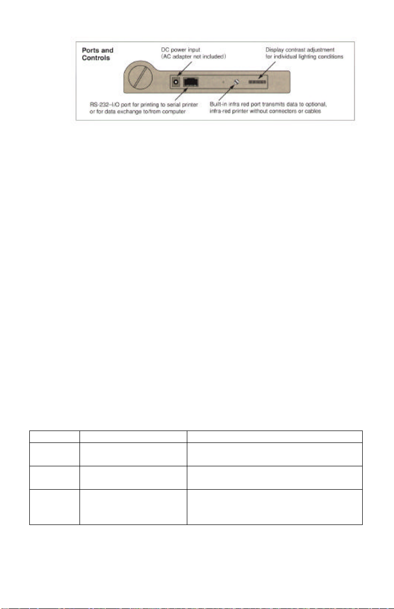
AC port - An optional AC adapter can be purchased from your dealer to
supply continuous 7.5 volts DC power from an AC source.
(pg.35)
RS232 Port - An RS232 compatible port is provided via this RJ45 interface
to send stored measurements or measurements-as-they-are-taken
to a serial printer, data collector or computer. Transmission is at
9600 baud, 8 bits, nonparity, 1 stop bit. Active only on Gages
with the Memory option (pg.13).
RESET Button - causes a “soft” or “safe” RESET as described on page 30.
IR Port - sends stored measurements to the optional IR Printer (pg.35).
The IR port is a send-only IR interface and is active only on
Gages with the Memory option (pg.13)
Contrast - adjusts the LCD to compensate for temperature and light
conditions.
Available Probes
Three (3) probes are available for the Model 100. They are interchangeable; one
can be removed and a completely different one installed. The probe type - B, C
or D - and serial number are engraved on the plastic probe connector. The probe
must be disconnected to view this information. The probe letter and serial
number can also be identified by selecting the Admin – About Gage menu
item. As new probes are attached, the Gage records probe type and serial
number to allow quick and easy reconnection at a later time. The probe reading
is independent of the Gage being utilized. The Gage can store calibration data
for up to 5 different probes. This information is cleared with a Gage
INITIALIZATION (pg.31).
Probe Measuring range** Typical uses
B
C
D
**the measuring range depends upon coating properties. See the Range &
Resolution Chart on page 41.
100 Series Page 9
0.3 to 20 mils
8 to 500 microns
2 to 175 mils
50 to 4.5 mm
48 to 350 mils
1 to 8 mm
thin coatings such as paint and urethanes
on wood, glass, plastic, etc.
thick paint or epoxy on concrete and
wood structures
thick, soft attenuative waterproofing
coatings on concrete and wood such as
polyurea and asphaltic neoprene
Page 10
LCD Display
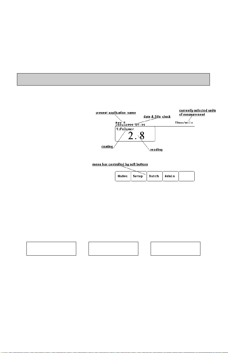
Information is displayed in one of four areas on the LCD: the top STATUS
BAR, the bottom MENU BAR, the left MEASUREMENTS area and the right
STATISTICS/GRAPHICS area.
Status Bar
An area along the top of the LCD is reserved for status information. This
includes the name of the current application (pg.19), the system date and time
(pg.33), the current units of measurement (pg.33), the current batch name and
number of readings. A ticking clock symbol appears occasionally to indicate an
action is being performed, such as a probe measurement.
Menu Bar
Most Gage operations are controlled by the five LCD buttons. When pressed,
each button activates a menu which pops up above that button. (The taking of a
coating thickness measurement is controlled by the probe switch).
These menus appear as follows:
Select
Language
Zero Initialize
Graphics Adjust Delete Change to
ON/OFF Reading Chart Microns
Statistics Gate/Zoom View/Edit Set
ON/OFF † Control Annotate Clock *
Memory Application Select About
ON/OFF * Setup New Gage
Modes Setup Batch* Admin OK
Button 1 Button 2 Button 3 Button 4 Button 5
Probe Print Gage
* - these 3 items are only available with the Memory option.
† - when Memory is ON,
this menu option appears as “Sets ON/OFF”
Page 10 100 Series
Page 11
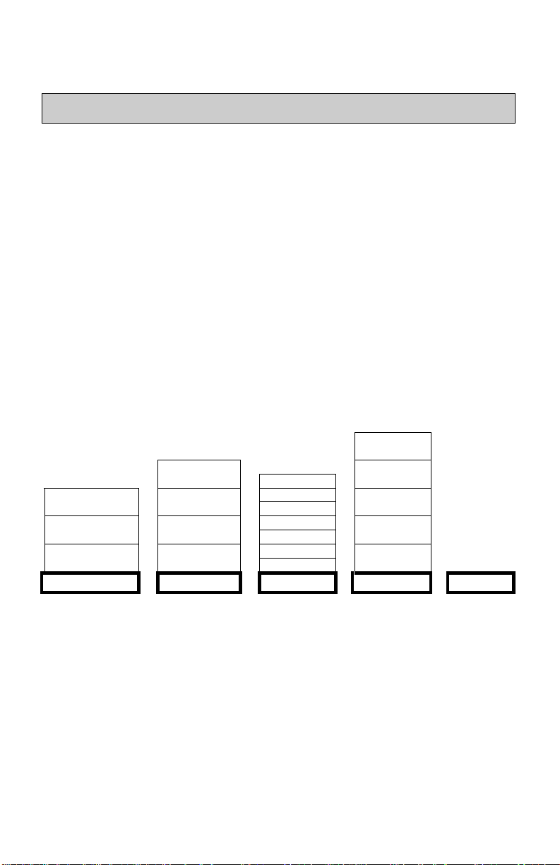
Measurements Area
The left hand side of the screen displays up to five (5) individual coating layers
as set by the Setup qq Application Setup menu option (pg.19). Each layer
is described in its own box.
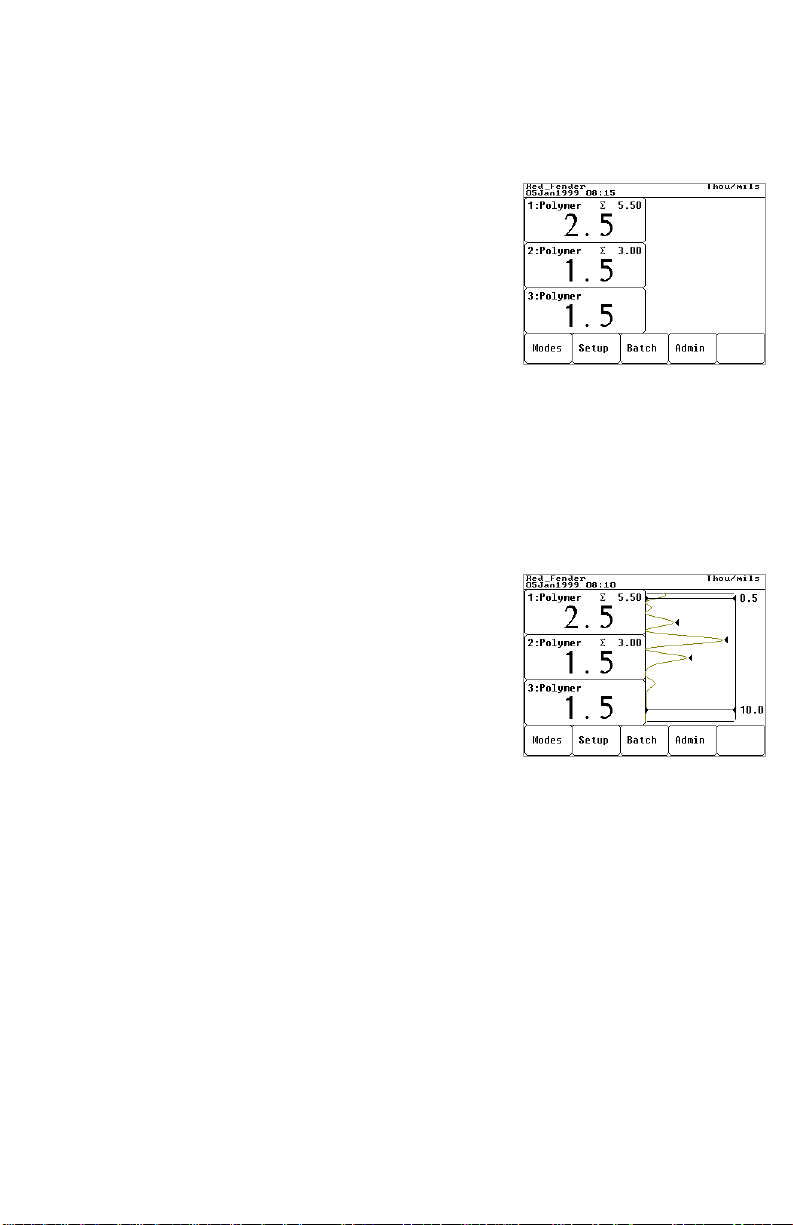
The number appearing in the top left of each box is
the layer number. The top box, layer 1, represents the
surface layer. The bottom box represents the layer
closest to the substrate. The coating name appears
beside the layer number.
The large number in the center of each box represents
the thickness of that coating layer in the measurement units shown in the Status
Bar. If GRAPHICS MODE is turned on, this value corresponds to the
appropriate triangle arrow.
The cumulative total of the individual layers is displayed in the top right of each
box as subtotaled from the bottom up. Therefore the ∑ value in the top box
represents the total coating thickness.
Graphics
The right hand side of the screen can be used to
display a graphical representation of the ultrasonic
echo as it passes through the coating system. It is
controlled by the Modes qq Graphics ON/OFF
menu option.
As the probe switch is depressed and the ultrasonic
pulse travels through the coating system, the pulse
encounters changes in density at the interfaces between coating layers and
between the coating and the substrate.
These interfaces are depicted by a “peak”. The greater the change in density the
higher the peak. The more gradual the change in density, the greater the width of
the peak. For example, two coatings layers made of essentially the same material
and “blended” would result in a low, wide peak. Two materials of very different
density and a well-defined interface would result in a high, narrow peak.
The Model 100 chooses the highest of peaks when trying to determine coating
layer thickness. If the number of layers is set to 3, for example, the 3 highest
peaks between the A & B Gates are selected as the interfaces between these
layers. The peaks that the Gage selected are indicated by black triangle arrows.
100 Series Page 11
Page 12
The top (A) and bottom (B) Gate values (pg.32) are displayed as two horizontal
lines at the top and bottom of the graphics area. Their current values are shown
to the right of each line. Gate A, the lower limit, is at the top. Gate B, the upper
limit, is at the bottom. Echoes or peaks (thickness values) outside these Gates
are ignored. GATE values are set and modified using the Setup qq
Application Setup menu option.
This GRAPHICS display can be manipulated with the Setup qq Gate/Zoom
Control menu option. In addition to being able to adjust the GATE values, a
CURSOR can be positioned anywhere between the two GATE values to
estimate other echo values.
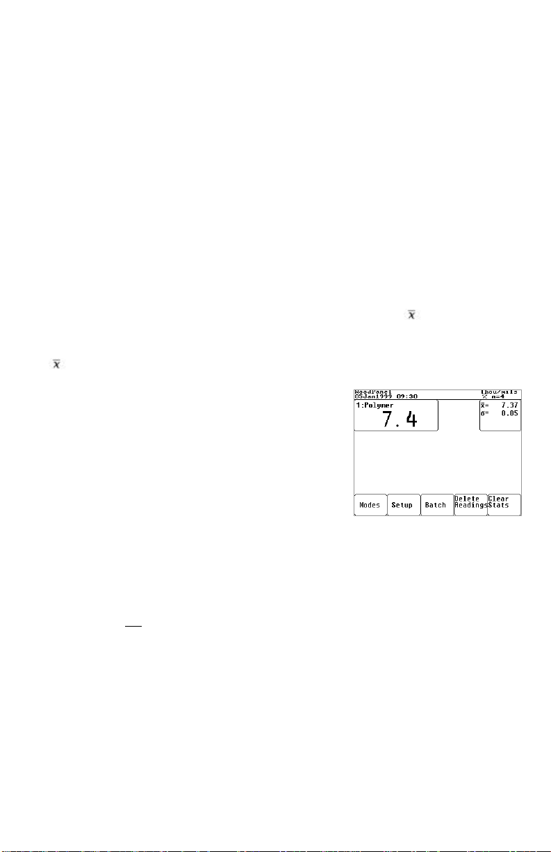
Statistics
When the Modes qq Statistics ON menu item is selected a symbol and a
counter (n=0) appear in the upper right of the display. If the graphics screen is
OFF a box will appear beside every layer box containing the average (mean)
and standard deviation σ values. If the graphics screen is ON statistics
calculations are done in the background.
As each measurement is taken, the readings are
displayed and the counter is increased. An incorrect
reading can be removed by selecting the Delete
Reading menu item before another reading is
taken.
Statistics calculations are erased by selecting
either the Reset Stats or the
Modes qq Statistics OFF menu items.
4 readings taken, last reading is 7.4 mils
Average=7.37mils. Standard Deviation is 0.05
If any layer contains a null result “- - - - -“ then the entire measurement attempt,
although displayed, is not included in the statistical calculations.
Readings are not stored in memory for later downloading.
Page 12 100 Series
Page 13
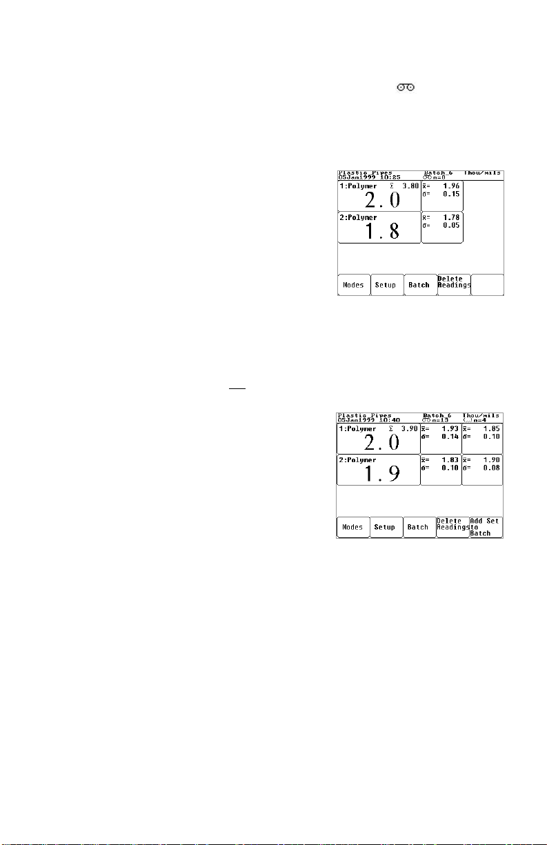
Memory
When the Modes qq Memory ON menu item is selected, a symbol and a
counter (n=0) appears in the upper center of the display. If the graphics screen is
OFF a box will appear beside every layer box containing the average (mean) χ
and standard deviation σ values. If the graphics screen is ON statistics
calculations are done in the background and results are still stored into memory.
As each measurement is taken, the readings are
displayed and the counter is increased. An
incorrect or unwanted reading can be removed
by selecting the Delete Reading menu item
before another reading is taken.
If any layer contains a null result “- - - - -“ then
the entire measurement attempt, although
displayed, is not included in the statistical
calculations and not stored into memory.
This mode is very similar to Statistics mode
8 readings are stored in the application
called Plastic_Pipes. Average of –1st coat
is 1.96mils -2nd coat is 1.78 mils. Total
coating thickness of the last reading is
3.80 mils.
except that measurement results are stored in memory for later downloading.
Sets
The Modes qq Sets ON/OFF menu item is
only visible when Memory mode is ON.
When both Memory and Sets modes are ON
individual measurements ARE NOT STORED.
Instead when the Add Set to Batch menu
item is selected the average, standard deviation
and number of readings are stored in memory.
The memory counter. will be incremented by
one and the sets counter will be reset to 0.
Statistical summaries are calculated for each
batch during printing. This delivers the
13 sets are stored in the application called
Plastic_Pipes. These sets contain only average
and standard deviation values. The average
thickness of coating1 is 1.93 mils. This
represents the average of 13 average values.
Four readings are in the current set which has
not yet been added to the application.
average of a set of average readings as
required by SSPC PA-2 guidelines.
100 Series Page 13
Page 14

Operation Overview
The Model 100 is an ultrasonic coating thickness Gage. As such it shares
characteristics with ultrasonic wall thickness gages and with magnetic and eddy
current coating thickness gages.
Like ultrasonic wall thickness gages, the Model 100 uses a transducer in the
probe to send pulses into the material to be measured and then measures the time
taken by that pulse to return to the probe tip. But unlike an ultrasonic wall
thickness gage the Model 100 is intended not to measure the total thickness of
the part but rather only the surface coating thicknesses. Thickness measurements
are therefore much smaller than those measured by ultrasonic wall thickness
gages. Secondly, the Model 100’s graphical representation of the echo returns
should not be confused with “A” scans presented by some wall thickness gages.
Like magnetic and eddy current coating thickness gages, the Model 100
measures the thickness of applied coatings. Where magnetic and eddy current
coating thickness gages measure the thickness of coatings over metal, the Model
100 is primarily intended to measure the thickness of coatings over non-metals.
It also has the additional capability of being able to measure the individual layer
thickness in a multi-layer coating system during a single measurement attempt.
Another difference: While the substrate plays a major roll in the operating
performance of magnetic and eddy current coating thickness gages, the coating
plays a relatively small roll. The opposite is true with the Model 100 because the
coating is the most important consideration when using the Gage and the
substrate is of relatively minor consequence.
It is always a good idea to verify that the Model 100 is operating properly before
measuring your application. This check makes sure the Gage has not been
damaged or altered in some way, perhaps by a previous user. There are a
number of ways to do this depending upon your requirements.
• calibration ensures measurements are traceable to a national standard
(pg.24)
• measure check standards at your work site (pg.44)
• measure a known thickness of previously measured material
• measure the included plastic shims (pg.28)
Before beginning any job be sure to check the settings found in Setup qq
Application Setup (pg.19) and alter them as necessary.
Page 14 100 Series
Page 15
Once you have checked Gage operation on a known thickness of material and
have modified current Application settings to most closely match your
coating/substrate combination you are ready to measure. Be sure to apply
sufficient couplant to fill voids in the surface and to fully wet the probe tip.
Multiple measurements in the same location may require additional couplant
every so often. Hold the probe steady when measuring and release the probe
switch after hearing the double BEEP. Leaving the Graphics Mode turned on
helps you to understand what the Gage sees and how it arrived at a thickness
measurement.
Never rely on a single measurement. It is important that several measurements
be consistent and repeatable, or as repeatable as your application will allow. If
the coating or substrate is rough or curved, use Statistics Mode to determine the
average of a series of readings. Comparing a series of averaged results will often
provide acceptable repeatability where individual readings might not.
Don’t be too quick to adjust a displayed reading to reflect what you believe the
coating thickness to be. Even though another measurement method might report
a different thickness, it is better to leave the Gage at its default settings and
evaluate repeatability first. The last step in any measurement application is
optimization using the Setup qq Adjust Reading / Adjust Velocity
menu option.
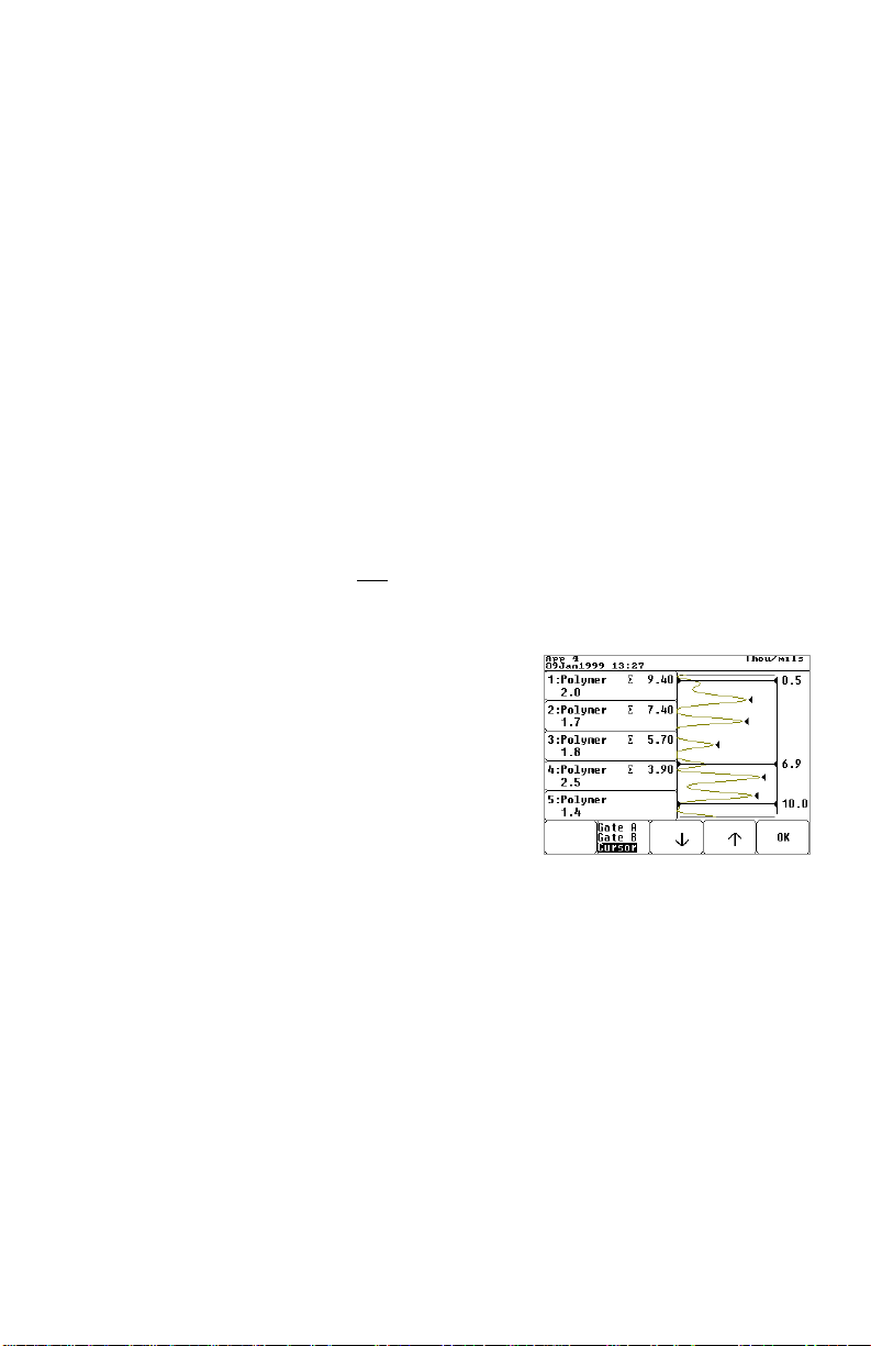
Whenever you run into difficulty, be sure to stop and
measure your Check standards, the plastic shims or
some other part you previously had success measuring.
Once you have made sure you are operating the Gage
correctly and that it is performing properly, return to
your application. Verify the settings found in Setup
Application Setup. Then select Setup qq
Gate/Zoom Control and, between
measurements, change Gate A and B values to observe
the reflected echoes. Use the cursor to measure peaks
not measured by the Gage (measured peaks have a
black triangle beside them).
Gage is set to its maximum 5 coats. The
5 largest peaks are displayed on the
left. However a 6th layer interface exists
at 6.9 mils (from the surface) as
measured by the CURSOR.
To measure properly, the ultrasonic echo must pass completely through the coating(s),
reflect off an acoustically dissimilar material such as the substrate or other coatings, and then
return unimpeded to the probe tip. Sometimes the coating is not homogeneous; it contains
solids or uncured sections that dampen or deflect the echo. Sometimes the interface between
coatings and the substrate is not distinct; the two materials have blended to create a
“transition” layer. Also the material may either be too thin or acoustically too thick or
attenuative to measure with an ultrasonic technique.
100 Series Page 15
Page 16

A visual inspection, such as that obtained by microscopically viewing a crosssectional cut of the material, often reveals useful information about your
application. It may also explain why the Gage behaves the way it does when
measuring your part.
Finally, you are always welcome to contact us at techsale@defelsko.com with
your inquiries. Be sure to include as much information about your application
and about the results obtained from known samples such as the plastic shims as
well as from the unknown material you are trying to measure. Provide us with
the Gage serial number and details about the material you are measuring and the
size and shape of the part. If all else fails you are welcome to send us a sample
of your application for measurement by our lab technicians.
Theory of Operation
The Model 100 uses an ultrasonic pulse echo principle. By transmitting an
ultrasonic pulse into the coating/substrate specimen and determining the time
taken for the pulse to travel to the coating/substrate interface and back to the
transducer, a coating thickness can be calculated.
Layer 1 is 2.5 mils thick. Layer 2 is 1.5 mils thick.
Layer 3 is 1.5 mils thick. Total thickness is 5.5 mils.
The most distinct interface is between layers 2 & 3.
The Gage transmits a high frequency, ultrasonic vibration into the coating using
a single element transducer. The vibration travels through the coating material
until a material with different mechanical properties is encountered, typically the
substrate. The vibration will be partially reflected and transmitted at the
interface between the dissimilar materials. The reflection will propagate back
through the coating and will be detected by the transducer. The transmitted
vibration will continue to travel into the substrate material and will also
experience reflections and transmissions at any material interfaces that are
encountered.
The transducer converts the reflections into an electrical signal which the Gage
digitizes. The digitized echo wave form is then analyzed to determine the exact
propagation time of the vibration.
Page 16 100 Series
Page 17

Since a potentially large number of echoes could occur, the Gage will choose the
strongest echo for use in coating thickness measurements. The assumption is
that the coating/substrate interface will provide the largest distance corrected
echo within the bracketed echo window (as defined by Gates A and B). The
coating thickness is calculated from the measured propagation time and the
velocity of propagation (sound velocity constant, vs) of the coating material. The
velocity of propagation is determined during optimization of the Gage against a
known coating thickness standard (pg.26).
The Model 100 uses deconvolution techniques to filter and enhance closely
spaced digitized echoes. These techniques make it possible to measure thin
coatings and coatings on acoustically similar substrates.
A menu is provided that allows an operator to select from a number of preconfigured coating and substrate classes. Using these class selections, the Model
100 can quickly be optimized to different coating/substrate combinations.
Couplant
Unless the coating is soft, couplant is required by the probe to transmit the
ultrasonic pulse into the coating. Water is an ideal couplant for smooth coatings.
Use the supplied glycol gel for rougher coatings. While it is unlikely that the
couplant will damage the finish or leave a stain on the surface, we suggest
testing the surface by using the couplant on a sample. If testing indicates that
staining has occurred, a small amount of water can be used instead of the
couplant. Consult the enclosed Material Safety Data Sheet and your coating
supplier if you suspect the couplant may damage the coating. Other liquids such
as liquid soap may also be used.
Power-up / Power-down
When any of the LCD buttons is depressed the Model 100 powers-up, performs
a self test and displays the last measurement(s). It then waits for the probe
switch to indicate the beginning of a measurement cycle. To preserve battery life
the Gage automatically powers-down after 2 minutes of inactivity when
operating on battery power or 8 minutes when operating off the optional AC
adapter (pg.35). There is no OFF button. All settings and readings are
maintained during power-down including the last measurement.
100 Series Page 17
Page 18

How to take a measurement
Apply a sufficient amount of couplant to the surface of your part.
After power-up, place the probe FLAT on the surface. Depress the probe switch
and hold the probe steady. While measuring, a “ticking” clock ∅ may
momentarily appear in the top status bar. The time required to take a reading
will vary. When measuring a new application for the first time the Gage may
take up to 5 seconds to acquire a reading. Subsequent readings are faster.
Release the switch when you hear a
double BEEP or see the green light blink.
Measurement results are displayed 1
second later.
A second reading may be taken in the
same spot by simply pressing the probe
switch again, or the probe can be lifted to
a new location before pressing the probe
switch.
During a measurement cycle the probe is excited and a thickness measurement is
derived. The result is simultaneously displayed on the LCD and transmitted out
the RS232 serial port.
When completely finished, wipe the probe clean of couplant and return both
Gage and probe to the protective case. There is no need to disconnect the probe
from the Gage during storage.
There is no “off” switch. The Gage will shut itself off and retain all stored
settings and readings.
Page 18 100 Series
Page 19

Applications
The Model 100 has the unique ability to store various settings for individual jobs
or coating thickness applications. For each, the user may choose to specify:
• the name of the application (memory option only)
• the type of substrate
• the type of coating
• the number of coating layers
• a special optimization setting for each layer
(sound velocity constant)
• Gate A & B settings
• the name of the user, part and batch (memory
option only)
Setting up and specifying applications enables the operator to easily switch
between parts, jobs, work sites and contracts for multiple products and
customers without the need for repeating the setup for each. These unique
“configurations” are stored as applications and can be recalled at any time.
Memory models store measurements in these applications as well.
One default application “App 1”comes preloaded in each Gage and cannot be
deleted. It is restored and reset to factory settings if a Gage INITIALIZATION
is performed (pg.31).
One application must be open at all times, but only one. When the Gage is new
or has been recently initialized, “App 1” is open. To create a new application
the user makes a copy of an existing one, then modifies the “copy”.
Applications are created and edited using the Setup qq Application Setup
menu item. On Gages with the Memory option, existing application names can
also be edited using PosiSoft (pg.34).
When the Setup qq Application Setup menu item is selected, the right
side of the LCD shows a list box of existing applications for the currently
connected probe only. Details on the highlighted application appear on the left
side of the LCD.
100 Series Page 19
Page 20

Select an Existing Application
Use the ↓ ↑ buttons located below the list box to move the highlighter to your
choice. Notice that details on the currently highlighted application appear
immediately in the left side of the LCD. Only applications created for the
currently connected probe are visible. Select the Setup qq Application
Setup qq Select an App menu item. Press the OK button to complete the
selection process. The application is now open to accept changes or stored
readings (memory option only). The name of the current application is listed in
the status bar at the top of the LCD. Memory mode must be turned off before
selecting a new application.
Edit Application Settings
Use the ↓ button located below the application details to move the highlighter to
the setting you wish to change. Some settings cannot be changed once readings
have been recorded in that application.
Create a New Application
New applications are created by simply making a copy of an existing application. First,
select an existing application as described above. Then choose Create a new App. A
new application name with a sequentially higher number will appear in the application list
box. The original application, however, remains as the current, open application.
For example: Four applications exist called App1, App3, App4 & App5. App2 was
previously deleted. App4 is current. When the Create a new App menu choice is
selected, App6 will be created with App4’s settings and App4 will remain current.
A new application is automatically created when a new probe is attached.
Delete an Existing Application
Select the Setup qq Application Setup qq Delete an App menu item.
Use the ↓ ↑ buttons located below the list box to move the highlighter to your
choice. Notice that details on the currently highlighted application appear
immediately in the left side of the LCD. Also note that all applications for all
probes are displayed.
Press the OK button to delete the highlighted application. All stored
measurements, names and settings are deleted and the application name is
removed from the list box. Once deleted this information cannot be recovered.
To exit the delete routine without making any deletion, select <none> from the
application list box and then press the OK button.
Page 20 100 Series
Page 21

Recording and Downloading Measurements
(available only on Gages with the Memory option)
The Model 100 can store measurement results for later downloading to a printer,
datacollector or PC. These values are stored in the currently selected application,
grouped by batch (file). These batches are unique to an individual application
and an application can have many batches.
Creating Batches
• To begin recording measurements into a new file choose the
Batch qq Create New menu option.
• To begin recording measurements into an existing file choose the
Batch qq Select menu option.
• To stop or resume recording, select the Modes qq Memory ON/OFF
menu option
The following symbols appear in the LCD status bar when recording is in
progress:
In this example, Batch_3 has been created but there are currently no recorded
measurements in that batch. The counter (n=0) is incremented every time a new
measurement or average value from a “set” is added to the batch.
New batch names are created sequentially regardless of application. If a batch
name is deleted it is not re-created. This sequencing is only restarted when the
Gage is INITIALIZED (pg.31).
Annotating Batches
Part and user names can be attached to batches.
These names are selected from list boxes created
on a PC using the supplied PosiSoft software
(pg.34) and uploaded into the Gage. These names
appear on printouts and with downloaded
measurements. There are no functions such as
sorting applied to these names. They serve only to
provide additional information and organization.
100 Series Page 21
Page 22

Viewing and Editing Batches
The Batch qq View/Edit screen not only allows the user to view stored
readings but also to delete and modify those readings. It also allows new
measurements to be added without having to return to the main screen.
To delete an existing measurement use the
↓ ↑ buttons to move the highlighter to your
choice and press the Delete key. Notice
that all layers in a multiple layer
measurement are deleted.
Deleted readings can not be recovered,
however they are not actually erased.
They are simply “flagged” as deleted
and can be viewed when downloaded
with PosiSoft. Deleted readings are not
included in statistical calculations.
Note that readings deleted with the
Delete Reading key on the main
screen are completely erased (pg.13).
Existing readings can be changed by
positioning the highlight bar over them and taking another measurement. The
new “modified” result is inserted in its place and identified with the letter “m”.
R = reading. C = coating layer number
Only the second (bottom) layer measurement of 2.1
mils is visible for the 1st reading. The 2nd reading has
an “m” beside it to indicate that the highlight bar
was positioned over it and another reading taken.
The 3rd reading has an “s” to indicate it is the
average result of a “set” of readings. The 4th reading
has been deleted. The highlight bar has been
positioned into the next available field to accept a
new measurement. The average of three layer1
readings is 7.67 mils.
Readings that are the calculated average of a “set” of readings (pg.13) are
identified with a letter “s”.
Additional measurement results can be added to the batch without affecting
existing stored readings by positioning the highlight bar at the bottom of the list
at the next available position (see illustration above) and taking a reading with
the probe.
Page 22 100 Series
Page 23

Charting Batches
The contents of the current batch can be viewed in graphical format by selecting
the Batch qq Chart menu item. A line chart or histogram is available for a
single layer or for all coats.
The batch name is “LabSample”. The application
“PlasticFender” is set to measure two layers. Ten
readings were taken but two were deleted.
Printing
Stored measurements (from one “application” at a time) can be sent formatted to
an infra-red or serial printer and can be captured by a Windows program such as
Windows HyperTerminal or MacTerminal. Measurements are not erased from
memory after being downloaded.
Choose the Batch qq Print menu item and select
the batch names you wish to group into a printout.
Press OK and then select a printer option.
1. Select the IR Printer option to print to the
Hewlett-Packard infra-red printer available
from your dealer. This portable, batteryoperated printer operates without wires, cables or connectors and is handy
for generating rapid, on-site printouts of stored measurements. Turn the
printer on and align it so that the Model 100’s red IR port is pointed at the
printer’s IR port at a distance of 6 inches (25cm) or less.
2. Select the Serial Printer option to print to any serial printer connected to
the Gage using the supplied RS232 cable.
A sample printout can be found in Appendix B. Graphics are
not printed
100 Series Page 23
Page 24

Calibration and Optimization
The Model 100 is factory aligned and does a self check each time it takes a
measurement. Periodically calibrate the Gage against known thickness
calibration standards to verify correct operation and determine if the Gage is
within tolerance.
Calibrate
⇒
Optimize
⇒
Measure
Overview
The operation of an ultrasonic coating thickness Gage is based on the transit time of
an ultrasonic pulse through a coating. The Gage measures this time and multiplies it
by a sound velocity constant for the type of coating material being measured. The
resulting value is displayed on the LCD as thickness.
To obtain optimum accuracy it is necessary to use the correct sound velocity
constant for the material being measured. The Model 100 has internally stored
constants that are set at the factory using NIST or NPL traceable reference materials.
To verify that the Gage is operating correctly make measurements of standards that
have a known thickness and are made of a material with a known sound velocity
constant. This allows you to verify that the Gage can measure accurately.
Calibration is the act of measuring known Thickness Calibration Standards and
verifying that the results are within the tolerance of the Gage. The Gage is calibrated
using the specific sound velocity constant for the reference standard material.
The actual sound velocity in materials often varies significantly from the values
found in published tables. A selection of coatings and substrates are programmed in
at the factory. At times it may be necessary to optimize the Gage to the material
being measured.
Optimization is the act of changing the Gage’s thickness reading or sound velocity
constant to match that of a known sample to compensate for the different velocity of
sound of the material being measured. Optimization does not effect the Calibration
of the Gage.
The Model 100 has an optimization mode (Optimize Reading) to allow for
matching the sound velocity constant used in the Gage to that of the actual material
being measured. To accomplish this, a measurement is made of a known thickness
of the material and the display is adjusted to the correct thickness reading. If a
known thickness is not available, factory settings can be used.
Page 24 100 Series
Page 25

The need to optimize is dependent upon a number of factors. If you are using
standard materials in your coatings and can select from the menu there is
probably no reason to optimize the Gage. On the other hand, if you need very
accurate measurements and are using non-standard materials it is suggested that
you optimize the Gage to your coating material prior to making actual
measurements.
Check standards may be made following the instructions given in Appendix A.
If you already have samples with a known thickness of your coating material
you may optimize the Gage to them. Review the material in Appendix A to
determine if your sample was measured to a sufficient accuracy for valid
optimizations.
Calibration
To calibrate the Model 100 you must have a set of Thickness Calibration
Standards. These Standards should have 3 to 5 values that cover the full range of
the probe being used. These standards must have been measured to an accuracy
that is four times or better than the accuracy of the Gage at the thickness being
measured. For example if the Gage has an accuracy at the measurement point of
±2 microns then the standards have to have been calibrated or verified to an
accuracy of better than or equal to ± 0.5 micron. Thickness Calibration
Standards are available from your dealer for each of the Model 100 probes. They
come complete with a certificate of calibration showing traceability to NIST.
Once you have Thickness Calibration Standards you can calibrate the Gage. Be
sure to use the correct sound velocity constant. Make several readings from each
of the standards. If the average of the readings at each point is within the
tolerance for the Gage for that standard then the Gage is operating properly
within specifications and you are finished the calibration.
If the Gage is not within tolerance, first verify that your standards are good and
then repeat the measurements. If the Gage is still found to be out of tolerance
you may want to try a second set of standards. If after this step the Gage is still
reading out of tolerance you should return it for service. There are no user
alignments available.
EFFECTS OF TEMPERATURE
Variations in temperature change the sound velocity of materials and transducer
delay tips. If measurements will be made in extreme hot or cold temperatures,
prepare and measure your Check Standards (see Appendix A) in the working
environment. The Model 100 should then be optimized using these Check
Standards in the same environment.
100 Series Page 25
Page 26

CALIBRATION INTERVAL
Start with a recommended interval of one year and adjust that interval according
to your individual usage and environment.
Optimization
Thickness measurement error is minimized by ensuring that the Gage has the
correct velocity value for the particular coating system being measured. This is
done by following a 2-step procedure:
1. SELECT A CATEGORY
2. OPTIMIZE TO A KNOWN THICKNESS
Since actual sound velocity in materials often varies significantly from the
values found in published tables, optimization of the Model 100 for velocity is
made by measuring a known thickness of the particular material being measured
and adjusting the displayed result to the actual, known thickness. If a known
thickness is not available, factory settings alone can be used.
The need to optimize is dependant upon a number of factors, not the least of
which is the level of accuracy required. To measure thin coatings for which a
high degree of accuracy is required, such as lacquer on wood with a B probe, for
example, the user may decide that optimization is needed. To measure thick,
rough coatings for which fine accuracy is not critical such as epoxy on concrete
with a C probe, the user may decide that only Step 1 (selection of a category) is
needed. To measure paint on plastic with a B probe and have traceability to a
standard, Steps 1 and 2 must both be performed.
When an adjustment is made to the sound velocity constant, the upper and lower
measuring limits of the probe change. A fast velocity value, such as for metal,
raises both the thinnest and thickest measuring limits of the probe. A slower
velocity value, such as for rubber, lowers both the thinnest and thickest
measuring limits of the probe. Table 4 on page 41 gives some examples.
STEP 1: SELECT A “CATEGORY”
Probes for the Model 100 come pre-adjusted for a variety of coating and
substrate types, or categories.
When a coating category is selected from the Coating
List, a typical sound velocity constant for that
material is used by the Gage. The number of coating
categories available to choose from depends upon the
type of probe that is attached. B probes have only one
category, polymer. The C and D probes have several
categories including polymer, rubber, glass and
metal.
Page 26 100 Series
Page 27

Since the substrate can often affect the return echo, all probes also provide the
user with a selection of substrate categories including concrete, wood, glass,
plastic, metal, ceramic and none to further refine the optimization.
To select these categories choose the Setup
Application Setup menu item. Use the ↓ button
to move the highlighter down to the Substrate:
line. A substrate list box will appear containing the
currently available list of substrates. Use the ↓ ↑
buttons located below the list box to move the
highlighter to your choice.
Now use the leftmost the ↓ button again to move the highlighter down to the
next line Coat 1:Polymer. A coating list box will appear containing the
currently available list of coatings. Use the ↓ ↑ buttons located below the list
box to move the highlighter to your choice. Repeat for each coating layer.
STEP 2: OPTIMIZE TO A KNOWN THICKNESS
It is recommended that a known thickness of your coating be measured with the
Gage to verify the correct sound velocity constant is being used. Make sure your
coating sample is smooth. The thicker your coating “standard” the better. If you
do not have suitable check standards, see Appendix A for instructions in making
a set.
Once you have your Check Standards you are ready to optimize the Gage.
Determine the range of acceptable readings using the thickness value of the
check standard and the accuracy specification of the probe you are using.
Example: You are making a measurement of a check
standard that has been verified to be 20.0 mils
±0.1mils. The Model 100 has an accuracy of ±0.7
mils (±0.1mil + 3% of reading) at this point. The
average of several readings should fall between 19.3
mils and 20.7 mils (20.0 – 0.7 and 20.0 + 0.7 mils).
Note that the check standard has an accuracy of ±0.1
mils and the Gage an accuracy of ±0.7 mils. The
check standard is 7 times more accurate than the
Gage.
Select a coating from the menu that is close to your type of material. Take
several measurements on the check standard. If the average of the readings at
each point is within the tolerance for the Gage then the Gage is operating
properly within specifications and you do not need to optimize the Gage.
100 Series Page 27
Page 28

If the average is not within tolerance, optimize
the displayed value up(+)or down(-) to match
the check standard thickness using the Setup
– Adjust Reading menu option. Measure
and adjust until you are satisfied that the
average of a series of readings equals the check
standard thickness.
Optionally if you know or have previously
recorded a sound velocity constant for this
material it may be adjusted instead of the
thickness value. For example the value for
the polystyrene probe tip is 80 mils per
The thickness value was changed from 1.2 mils
to 1.4 mils. The sound velocity constant changed
from 86 to 100.81 mils/microsecond.
Notice the coating name automatically changed
from “Polymer” to “Polymer1”.
microsecond. The value for the epoxy
coated metal Calibration Standards (pg.35) is 101.56 mils/microsecond. The
value for steel is approximately 250 mils/microsecond.
The Gage is now optimized for your coating. The sound velocity constant for
your material is shown in the upper right corner of the layer box. Normally, the
optimization process does not have to be repeated unless the coating material
changes. However it is a good idea to periodically re-measure the "check
standard".
Plastic Shims
A variety of colored precision plastic shims are included. They provide a quick
operational check of the Gage and help insure the operator is using it properly
by enabling them to practice various measuring techniques. Plastic shims are not
always manufactured with the same material. Therefore it is not important that
the Gage measure their exact thickness, rather readings should be consistent.
To measure shim thickness:
• zero the probe using the Setup qq Zero Probe menu item (pg.29)
• select the default coating “polymer” from the Setup qq Application
Setup menu item (pg.19). Select a substrate category of “none”
• place a shim on any flat, hard surface. Apply couplant on top of the shim
and measure it.
Page 28 100 Series
Page 29

Advanced Features
Zeroing the Probe
The probe must be periodically zeroed using the Setup qq Zero Probe menu
item to compensate for both temperature and probe wear effects. (This is not to
be confused with measuring an uncoated substrate to get a 0.0 reading!) Allow
the probe to reach ambient temperature. Wipe the probe clean of gel.
Temperature changes directly affect Gage measurements by expanding
and contracting the probe’s plastic delay tip. Constant handling and measuring
on a hot surface, for example, will warm the probe. Storage in an outdoor winter
environment will cool and contract the probe tip. The B probe compensates for
temperature automatically during each measurement. But the C and D probes
must be manually compensated using the Setup qq Zero Probe menu item.
This menu item should be selected every hour of measurement for the C and D
probes to compensate for temperature; more often in a changing temperature
environment or when first beginning to measure after an extended power-down.
Probe wear also directly affects Gage measurements but usually in a
less dramatic fashion. Compensation must be made manually for all probes
using the Setup qq Zero Probe menu item. This menu item should be
selected at the beginning of each day to compensate for wear; more often when
measuring on rough coatings.
Occasionally, the message “Probe must be zeroed” will appear when a
new probe is connected or when probe calibration data is lost such as when
“INITIALIZING” the Gage (below).
100 Series Page 29
Page 30

Restarting the Gage
As with any electronic device, harsh temperature, electromagnetic environments
or rough handling may alter the performance of some Gage components causing
the Gage to exhibit unusual behavior.
Two features enable the Gage to recover from many of these disturbances
without the necessity of returning the Gage for service: RESET and
INITIALIZATION. These actions help overcome a lock-up condition or other
erratic Gage behavior. They also help prevent costly service delays.
GAGE RESET
This is a non-destructive action. It simply restarts the internal software program
and does not affect any stored user settings or data.
A Gage RESET is activated by pressing the RESET button (pg.9) on the topside
of the Gage. Use a pen tip or other similar object to push this recessed switch at
any point in the Gage operation. If the Gage is powered-up it will immediately
power-down. If the Gage is powered-down when the switch is pushed it will
stay powered-down. The RESET action occurs when the Gage is next poweredup.
When selected:
• names and settings created by the user for unique coating applications are
not lost
• for Gages with the Memory option, stored measurements and downloaded
user configurations/lists are not lost.
If the RESET is successful, the Gage display should return to the point it left off
when the RESET button was pressed. However, if the RESET was performed to
clear an unusual Gage condition, it is recommended that the Gage be
INITIALIZED at the earliest opportunity.
If the RESET is unsuccessful in restarting normal Gage operations, INITIALIZE
the Gage as described below.
Page 30 100 Series
Page 31

GAGE INITIALIZATION
This is a destructive action. It not only restarts the internal software program,
but it also erases all stored user settings or data and returns the Gage to a known
out-of-the-box condition.
This action:
• performs a Gage RESET as described above
• erases all readings in memory
• erases all stored probe information
• erases all user created or downloaded configurations and list boxes
• turns off Memory, Statistics and Graphics modes
• begins application and batch names at number 1
• erases all applications and restores default App1 (1 coat of “polymer” on
substrate “none”)
• is handy when uncertain what previous changes have been made to the
Gage such as when beginning a new job or taking possession of the Gage
from a previous owner/operator
NOTE: For Gages with the Memory option, stored measurements and
downloaded user configurations/lists are deleted during this
operation. If the user wishes to keep these values, they should
first be downloaded by PosiSoft onto a computer. List box
contents can be re-loaded into the Gage after the
“Initialization” has been successfully performed.
There are two ways to INITIALIZE the Gage. The first is by selecting the
Admin qq Initialize Gage menu item. The second method is to first press
the RESET button and then power-up the Gage by simultaneously pressing and
holding the left-most AND right-most buttons until a BEEP is heard.
100 Series Page 31
Page 32

Gates A & B
Each probe has a measuring range as shown in the chart on page 41. For
example, the C probe can measure polymer coatings in the range of
approximately 2 to 175 mils (50 to 4500 microns). However, there are times
when it is not desired to inspect this full range of thickness.
Gates are used to narrow the range of thickness that the Gage examines. Gate A
sets the minimum thickness limit and Gate B the maximum. These values are
adjusted to:
• increase the resolution of the graphical display
• make the Gage ignore echoes from other sources such as surface echoes and
echoes from within the substrate
• improve the resolution of the displayed measurement results
• reduce the likelihood of the Gage registering other than what the user
intended to measure
There are two ways to adjust the Gates. If the Graphics display is visible, use the
Setup qq Gate/Zoom Control menu item to change the scale of the
display. If the Graphics display is OFF, use the Setup qq Application
Setup menu item to simply adjust their values.
When measuring, the Gage looks for a distinct interface within the two Gate
settings. If the actual thickness is outside this range, incorrect or dashed readings
occur.
Gate A should be high enough to prevent the Gage from reading surface
roughness. Unusually thin readings indicate that the Gate A value may be set too
low.
Gate B should be low enough to prevent total thickness measurements of both
the coating and substrate. If results are twice the expected thickness, lower the
value of Gate B.
Here are some typical setups...
Expected paint thickness Gate A Gate B
20 mils (500µm) on concrete 5 mils 150µm 40 mils 1000µm
2 mils (50µm) on wood 0.5 mils 13µm 10 mils 250µm
Page 32 100 Series
Page 33

Measurement Units
The currently selected units of measurement are displayed in the top right corner
of the LCD status bar. This can be changed from inch to metric or vice versa
using the Admin qq Microns Thou/mils menu item. The displayed
reading(s) and all stored readings are converted.
System Clock
(available only on Gages with the Memory option)
The Model 100 records the date and time as each measurement is stored. This
information is downloaded along with the measurement information. The
current date and time is displayed in the status bar at the top of the LCD and can
be changed using the Admin qq Set Clock menu item.
Language Option
The Model 100 has the ability to display in a variety of languages. Use the
Admin qq Select Language menu item to select your choice. Screen space
limitations have forced some shortening of words. Obscure terms have been left
in English.
100 Series Page 33
Page 34
Communications – (memory option only)
Model 100 “memory” Gages can communicate with other devices such as PC’s,
serial printers and data collectors via either the built-in infra-red port or the
RS232 connector using the supplied serial cable.
Printing
Stored measurements (from one “application” at a time) can be sent formatted to
an infra-red or serial printer and can be captured on a computer using a COM
program such as Windows HyperTerminal or MacTerminal. Measurements are
not erased from memory after being downloaded. See page 23 for full details. A
sample printout can be found in Appendix B.
PosiSoft
PosiSoft ™ for Windows is supplied at no additional charge with all Gages with
the memory option. It runs on PC-type computers running Windows95, 98, NT
or higher version and having a COM port.
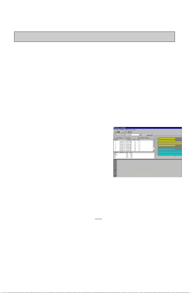
PosiSoft provides the user with a tool for
monitoring and analyzing a coating thickness
process. When Gage readings are downloaded
to PosiSoft, the results may be saved to
separate files for analysis. PosiSoft quickly
generates Histograms, Control Charts and a
Statistical Summary.
Full operating instructions can be accessed by first installing the software,
starting the program and then selecting the Help qq PosiSoft Help menu
option.
Downloading Measurements As They Are Taken
After each measurement cycle a thickness measurement is derived and the result
is simultaneously displayed on the LCD and transmitted from the RS232 serial
port at 9600 baud, 8 bits, nonparity, 1 stop bit. Output is in the following form
(example):
{STX}2,Polymer,•••••••2.5,Polymer,•••••••1.2,concrete,mils{CR}{LF} where:
STX = ASCII code 02 = ^B concrete = substrate category
2 = number of coats (layers) mils = units
Polymer = coating category CR = ASCII code 13 = ^M
• = space LF = ASCII code 10 = ^J
2.5 =thickness measurement for layer1
Page 34 100 Series
Page 35

Serial Communications Configuration
Existing communication software can be used, providing it can capture data
from a COM port. By selecting "PRINT ?" on the Gage MENU, your computer
will accept the measurements in the printer format.
8 bit words, no parity, 1 stop bit
9600 baud
XON-XOFF handshaking
The supplied serial cable is RJ45 to DB9 F
Pinout Description
2 TXD Transmit data (from Gage)
3 RXD Receive data (from PC or Printer)
5 GROUND
Available Options
Memory
This software feature enables the Gage to record measurements,
basic statistics and annotations by group. These values can be
downloaded to either a printer, data collector or computer.
Additionally, lists of user, part, application and batch names can
be uploaded into the Gage. PosiSoft software is supplied when
the Memory option is ordered.
HP IR Printer
A convenient, portable printer is available for use with Gages
having the Memory option. The Gage transmits data to this
battery operated printer through the infra-red port without
connectors or cables.
AC Adapter
Power normally comes from two ‘C’ alkaline batteries. An AC adapter is
available to supply continuous 7.5 volts DC power from an AC source. This is
handy when doing extensive testing in a lab environment where the Gage will
remain in one location. When the AC adapter is being used, the batteries should
remain in the Gage in case of a power interruption. Do not use any AC adapter
other than the approved model supplied by the manufacturer.
(Model SPU I5A-1-1)
Traceable Standards
Calibration standards are available for each particular probe.
(pg.24). They are ideal for ISO 9000 compliance and for
verifying the operation of your Gage.
100 Series Page 35
Page 36

Measuring Notes
Rough Substrates
In smooth coating/substrate conditions where there is a distinct interface, the
echo is clear and sharp. This results in a repeatable measurement with a sharp,
narrow peak on the graphical display. When the substrate has a surface
consisting of many peaks and valleys, numerous and varied echoes are received
from the interface.
In this occurrence, the Gage received the strongest echo from the
peaks and measured the coating thickness as 25.7 mils. The cursor
has been turned on and located over the 2nd attached peak to
estimate the coating thickness over the valleys as 28.4 mils.
The Model 100 tends to average these reflections and presents them graphically
as a wide peak. Although successive measurements are not repeatable, they
should be close, depending upon the amount of roughness. It is a good idea to
use a statistical average (Modes qq Statistics ON - pg.12) to determine
thickness. When peak and valley depths are consistent, sometimes a “shoulder”,
or attached peak, is visible. This secondary peak can be measured by positioning
the cursor (Setup qq Gate/Zoom Control - pg.32) over it.
Transition Layers
Some coatings “blend” into previous coats or into the substrate. This indistinct
interface produces an echo that is neither clear nor sharp. In these situations it is
difficult to obtain a repeatable measurement. The graphical display shows a
wide peak with a rounded top.
Page 36 100 Series
Page 37

Maintenance and Troubleshooting
Battery Management
The Model 100 obtains power from three potential sources:
• two 1.5v ‘C’ size Alkaline-Manganese Dioxide batteries. If they run low,
the Gage will save all user settings and readings, then power-down.
• an optional AC adapter (pg.35) supplying 7.5 volts DC power. While in use,
two alkaline batteries should remain in the Gage in case of a power
interruption.
• a lithium cell which provides approximately 30 minutes of back-up power
to retain all user settings and readings while the two “C” batteries are
removed. The Gage cannot be operated on this cell.
Power normally comes from the two ‘C’ alkaline batteries. As they become low,
a symbol will appear on the LCD. The Gage can still be used in this
condition but the batteries should be changed at the earliest opportunity. Always
change both batteries at the same time, never just one. Don’t mix old and new
batteries.
If you don’t change the batteries in time, the Gage turns itself off automatically
to save the information in its memory. You can turn the Gage back on once
you’ve replaced the batteries or plugged in the optional power adapter.
The lithium cell will last for more than 10 years of normal to heavy use. It
cannot be replaced by the user. It will retain all user settings and readings while
the Gage is powered-down for a 30 minute period to allow you to replace the old
‘C’ batteries with two new ones. This back-up power retains all user settings and
readings but is not sufficient to operate the Gage. If the 30 minute period is
exceeded, the Gage automatically cuts off power from the lithium cell and will
then experience a power failure. This is the equivalent of a Gage initialization
(pg.31) except that all stored calibration settings and downloaded user
configurations/lists are not lost.
Open the battery door by using your thumb and index finger to turn the door a
quarter turn to the left. Take note of the proper battery orientation when
replacing the batteries (see Gage backplate). If you install the batteries the
wrong way, the batteries may leak and damage the Gage. Leaking batteries may
be hazardous and any damage caused by leaking batteries is not covered by the
warranty.
USE ONLY 1.5v “C” ALKALINE BATTERIES
NOTE: Nickel-cadmium and nickel-metal hydride rechargeable batteries
will work however the low battery symbol may stay on.
100 Series Page 37
Page 38

Troubleshooting
Gage does not turn on
The Gage powers up but
fails to stay on
The screen appears too
light or too dark.
Gage does not yield
accurate or consistent
results
Batteries don’t last as
long as they used to.
Measurements are much
lower than expected
Measurements are much
higher than expected
Gate A and B cannot be
extended to maximum
Readings are not
repeatable (fluctuate)
• make sure each battery’s + and – terminals are
positioned properly and that the batteries are
fresh Alkaline ‘C’ cells
• make sure the probe connector is fully pushed in
• try adjusting the screen contrast
• press the RESET button
Replace batteries. If problem persists return Gage for
service
• adjust the contrast
• adjust your viewing angle
• adjust the surrounding lighting
• make sure the Gage is not too hot or too cold. It is
designed to be used in temperatures between 0
and +40C.
See the Calibration and Gate sections to ensure that
Gage is properly configured for your application.
Check the Gage on traceable standards.
The more you use the communication port for
downloading, the faster the batteries will loose power.
Extensive use of the menu system with the 5 LCD
buttons will also use more power.
Gage may be measuring surface roughness. Raise the
value of Gate A.
Gage may either "doubling" or measuring both
coating and substrate. Lower the value of Gate B.
The user may have optimized the Gage and changed
the sound velocity constants. See the Range and
Resolution Graph on pg.41 for range of each probe.
It is not unusual to get a variety of readings at the
same spot with any coating thickness gage particularly
if the substrate or coating surface is not completely
smooth. The Model 100 is also affected by surface
roughness. However fluctuations in the amount of
pressure applied and the amount of couplant used are
also a factor when measuring very thin coatings. As
long as these variations are within the tolerances of
the Gage there is no cause for concern. If you are
having problems, provide application details.
Page 38 100 Series
Page 39

Service
Before returning the Gage for service, attempt to clear the problem by…
• installing new, “C” alkaline batteries (pg.37), and
• performing a RESET (pg.30), and if still necessary
• performing a Gage INITIALIZATION (pg.31)
to restore factory settings and to return the Gage
to an “out-of-the-box” condition.
For service, ensure the following:
• return Gage, probe and all related material,
including samples if appropriate
• include company name, return address, contact
and fax number
• describe the problem as completely as possible
Specifications
Due to continuous process improvement, specifications are subject to change
without notice.
ASTM
The Model 100 conforms to ASTM D6132 – Standard Test Method for
Nondestructive Measurement of Dry Film Thickness of Applied Organic
Coatings Over Concrete Using an Ultrasonic Gage. The Scope of this Test
Method states, “This test method covers the use of ultrasonic film thickness
gages to measure accurately and nondestructively the dry film thickness of
organic coatings applied over a substrate of dissimilar material”. The Test
Method is available from ASTM in West Conshohocken, Pennsylvania, USA at
telephone number (610) 832-9500.
Temperature
Variations in temperature change the velocity of sound in materials, including
the probe. All optimization should be performed on-site with check standards at
the same temperature as the test piece in order to minimize errors due to
temperature variations.
The operating range for the Model 100 is +32 to +100F (0 to +40C). The Gage
compensates automatically for temperature within its operating range. “B”
probes also compensate automatically. “C” and “D” probes are not temperature
compensated and should be allowed a few minutes to reach ambient temperature
before measuring. These two probes should be ZEROED when temperature
changes are suspected (pg.29).
100 Series Page 39
Page 40

When measuring surfaces much hotter or colder than ambient, lift the probe off
the surface for several seconds between measurements and zero the probe
periodically to assure the most accurate readings.
NOTE: Discard the first measurement taken in a notably different temperature
condition.
Table 1: Physical Characteristics
Dimension Measurement *
Width 9 inches (23 cm)
Height 8 inches (20 cm)
Depth 1.5 inches (4 cm)
Weight 2.2 lbs. (1kg)
*including pouch and batteries
Table 2: Environmental Characteristics
Characteristic Temperature Relative Humidity
Storage
Operating
-10°C to +70°C
14°F - 150°F
0°C to 40°C
32°F to 100°F
70%
80%
Table 3: Operational Characteristics
Characteristic Measurement
Accuracy** ± 0.1mil + 3% of reading
Power Source Two 1.5volt “C” alkaline batteries
Power Consumption 600 mw
Battery life over 12hrs or 2000 readings
Probe cable 4 ft (1.2 meter) with integral probe switch
Pulser Voltage 180V (non hazardous)
Pulser Type Capacitive discharge
± 2.0 microns + 3% of reading
** accuracy the Gage is capable of achieving when adjusted to the appropriate sound
velocity constant of the material being measured.
Page 40 100 Series
Page 41

Table 4: Range and Resolution Matrix
The measuring range for the Model 100 is determined by the sound velocity
constant of the coating(s). Both the low and high limits of the Gage’s measuring
range increase for materials with high velocity constants such as aluminum, and
decrease for materials with low velocity constants such as rubber.
Note: These ranges and resolutions are default acoustic properties.
Optimization adjustments may alter the ranges and resolutions
available.
100 Series Page 41
Page 42

Safety and Regulatory Information
For your protection, this instrument has been tested to various national and
international regulatory standards. This regulatory testing includes
electrical/mechanical safety, radio interference, ergonomics, acoustics and
hazardous materials.
Page 42 100 Series
Page 43

100 Series Page 43
Page 44

Appendix A - Making Your Own Check
Standards
Once you have calibrated your Gage you may wish to make some Check
Standards for use at the work site. These Check Standards should be made of the
particular material you are using on the job to best match the measurement
conditions. The linearity and accuracy of the Gage are verified during
calibration against a known thickness and coating material. Once the Gage is
calibrated it can be adjusted to a new sound velocity constant without effecting
its accuracy. Care must be taken during the adjustment process. Sloppy
technique may introduce systematic errors into your readings.
A major condition of making standards is the requirement to maintain
measurement traceability through proper technique and uncertainty analysis. It
appears quite simple to coat a substrate with your material to use as a standard.
But it is necessary to be able to measure the thickness of that coating to an
accuracy better than that of the Gage. According to various directives and
common usage, the measurement of the thickness standard has to be at least four
(4) times better than the accuracy of the Gage at that thickness reading. Lets
look at an example.
Say you are trying to prepare a Check Standard for use with the Model 100 with
a C probe at a thickness of 40 mils for an Imperial example or 1000 microns for
a metric example. The accuracy of the C probe at this thickness is calculated as:
Accuracy = ± 0.1 mil + 3% of reading
Accuracy = ± [0.1 + (0.03)(40)] = ± 1.3 mils
Accuracy = ± 2 microns + 3% of reading
Accuracy = ± [2 + (0.03)(1000)] = ± 32 microns
Therefore the Check Standard must be measured to better than one-fourth of this
accuracy or ±0.325 mils or ±8 microns or better. In this case we can use a
precision micrometer that has been calibrated to an accuracy of ± 0.1 mil (±2.54
microns) or better. If you have a micrometer that has been calibrated to this
accuracy, you can go ahead and follow the rest of this procedure and make your
Check Standards.
Page 44 100 Series
Page 45

Preparing Your Standards
1. Measure a suitable substrate (uncoated ) with a calibrated micrometer (± 0.1
mil, ±2.54 microns or better). The substrate does not have to be the same
material to which your coating will be applied. It should be smooth as
possible to give a good clean reading. The sample substrate should also be
at least four times the thickness of the coating being applied.
2. To be sure the Gage does not see the back wall of the substrate, adjust the
Gate “B” setting to be approximately two times the expected coating
thickness.
3. Coat the substrate with the material to be used to a thickness of at least 20
mils. This is required to maintain the accuracy ratio between the Gage and
the measurement capability of the micrometer.
4. Measure the total thickness of the substrate and coating with the calibrated
micrometer.
5. Calculate the coating thickness. (thickness = step 4 minus step 1)
6. Using the Model 100, measure the coating thickness.
7. Follow the procedure for adjusting the Gage (pg.26) to set the reading to the
thickness calculated in step 4. Record the sound velocity constant for your
check standards.
You are now ready to make your production measurements. The Gage has been
adjusted to the sound velocity constant needed for the specific material in use.
Periodically check your Gage with the Check Standard. If you change your
coating material you should create new Check Standards.
The above procedure will only work, using a ±0.1mil accuracy micrometer, for
Gages designed to measure 15 mils or greater in thickness. For making Check
Standards thinner than 15 mils requires much more accurate measuring devices.
If you have multiple probes for your Model 100, you can use any probe to make
a Check Standard of greater than 15 mils, then use that Check Standard to adjust
the sound velocity constant for use at all ranges of the probes.
100 Series Page 45
Page 46

Appendix B - Sample HP IR or serial printout
One batch containing 4 readings taken on a 2-layer coating system.
-----------------------09Jan1999 12:08
Batch: Batch_7
App: App 1
User: (none)
Part: (none)
Substrate: none
Coating1: Polymer
Coating2: Polymer
Probe Model: 100 B
Probe s/n: 1013
-----------------------Readings were taken between
09Jan1999 11:48
and
09Jan1999 12:22
----------------------- # Value StdDev n
1:1 71 →reading#1, layer#1
1:2 33 →reading#1, layer#2
2:1 70
2:2 28
3:1 65 →reading#3, layer#1
3:2 31 →reading#3, layer#2
4 Deleted
5:1 68
5:2 31
-----------------------N: 4
Layer: 1
StdDev(1): 2.6458 microns
Max(1): 71.00 microns
Mean(1): 68.5000 microns
Min(1): 65.00 microns
Layer: 2
StdDev(2): 2.0616 microns
Max(2): 33.00 microns
Mean(2): 30.7500 microns
Min(2): 28.00 microns
Page 46 100 Series
Page 47

100 Series Page 47
Page 48

Warranty
The manufacturer fully warrants its products against defects in workmanship or
materials for a period of one year from date of purchase. In the event that a Gage
is found to be defective, return the product to your dealer and the defective
product will be repaired or replaced at the manufacturers option.
No responsibility is assumed for incidental or consequential damages. The
warranty is voided if the Gage has been opened. Data subject to change without
notice.
802 Proctor Avenue, P.O. Box 676
Ogdensburg, New York 13669-0676 U.S.A.
Tel: (315) 393-4450
Fax: (315) 393-8471
email: techsale@defelsko.com
web: www.defelsko.com
DeFelsko Corporation USA 1999
All Rights Reserved • Patents applied for • Printed in U.S.A.
Page 48 100 Series
 Loading...