

Page 1
Instruction Manual v.1.2
Shore Hardness Durometer
Page 2

Page 3
Do not place the indentor on hard materials such
as steel or glass. Doing so may damage the indentor and cause the
probe to read out of tolerance. Replace the rubber cap to protect the
indentor and presser foot when not in use.
Damage to the indentor caused by measuring on hard materials is
not covered by DeFelsko’s warranty.
1
Introduction
Introduction
The PosiTector Shore Hardness Durometer (SHD) is a hand-held
electronic instrument that measures the indentation hardness of
non-metallic materials. It consists of a PosiTector body (Standard or
Advanced) and an interchangeable probe (SHD-A or SHD-D).
This Quick Guide summarizes the basic functions of the gage.
Download the full instruction manual at www.defelsko.com/manuals
Quick Start
Quick Start
The PosiTector SHD powers-up when the center navigation
button is pressed. To preserve battery life, the Gage powers
down after approximately 5 minutes of no activity. All settings are
retained.
1. Remove the protective rubber cap from the probe.
2. Power-up the Gage by pressing the center navigation button .
Ensure the probe indentor (pg. 2) is not in contact with any
surface.
3. Measure
a) Press the probe down onto the material to be measured until the
presser foot is in full, flat contact with the surface. HOLD STEADY
against the surface.
b) The Gage will emit a single BEEP and display a ▼ symbol
indicating a reading is being taken. The test timer will begin
counting down (see Test Time, pg. 5). When the timer reaches 0s,
the Gage will BEEP twice and display the measurement value.
4. Lift the probe from the surface between readings.
IMPORTANT:
Verify accuracy (pg. 3) on test blocks at the beginning and the
end of each shift, or if the gage is dropped or suspected of giving
erroneous readings.
Page 4
2
Probes
Probes
When powered-up, the PosiTector automatically determines which
probe is attached and does a self-check.
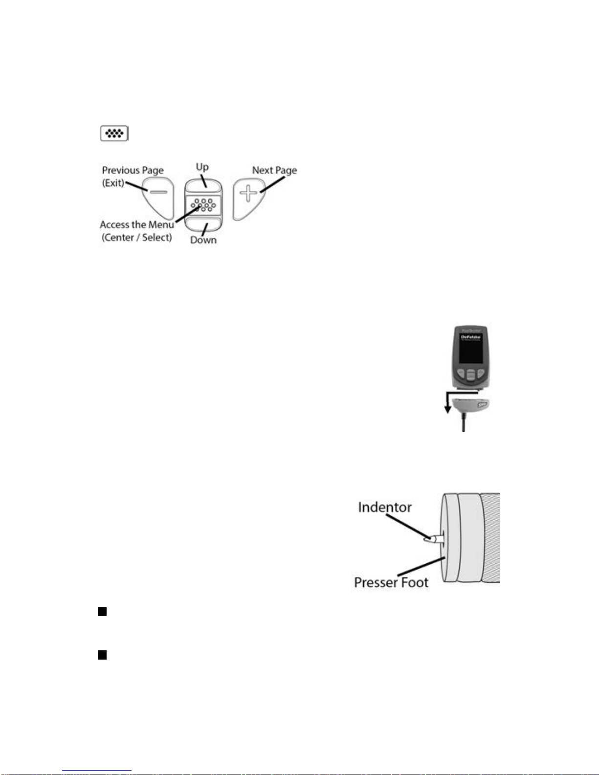
To disconnect a probe from a body, slide the plastic probe
connector horizontally (in the direction of the arrow) away
from the body. Reverse these steps to attach a different
probe. It is not necessary to power-down the Gage when
switching probes.
The PosiTector gage body accepts a wide variety of
probe types including magnetic, eddy-current and ultrasonic
coating thickness, surface profile, environmental, hardness,
salt contamination and ultrasonic wall thickness probes.
See www.defelsko.com/probes
The PosiTector SHD probe consists of
an indentor, calibrated spring and a
presser foot.
Two probe models are available for
measuring on a variety of materials:
PosiTector SHD-A (Shore A)
soft rubber, elastomers, neoprene, silicone, etc.
PosiTector SHD-D (Shore D)
hard rubber, epoxies, hard plastics, PVC, acrylic, etc.
To navigate, use the Up and Down buttons to scroll vertically and
to SELECT.
Press the (+) button to switch
pages in a multipage menu.
Press the (-) button to return to
the previous menu or page.
Select Exit to exit from any menu.
Menu Operation
Menu Operation
Gage functions are menu controlled. To access the Menu, power-up
the gage, then press the center navigation button.
Page 5

3
Calibration, Verification and Adjustment
Calibration, Verification and Adjustment
Three steps ensure best accuracy…
1. Calibration - typically performed by the manufacturer. All probes
include a Certificate of Calibration.
2. Verification of Accuracy - typically performed by the user on
known reference standards such as the included test block.
3. Adjustment - to a known hardness
Calibration
Calibration is the high-level, controlled and documented process of
measuring traceable calibration standards over the full operating
range of the probe, and verifying that the results are within the stated
accuracy of the probe. Calibrations are performed by the
manufacturer, their authorized agent, or by an accredited calibration
laboratory in a controlled environment using a documented process.
Verification
Verification is an accuracy check performed by the user on known
reference standards. A successful verification requires the Gage to
read within the combined accuracy of the probe and the test blocks.
Instrument operation may be verified with the included test block.
Place the test block on a flat, hard surface and take three to five
readings. The measurement points should be at least 6mm (0.24”)
apart. If the average of those readings is outside than the combined
accuracy of the test block and gage, the gage may require service.
Some causes for the gage to not read properly are the indentor
being damaged, incorrect pressure being applied to the test block or
temperatures beyond normal conditions.
Verify accuracy at the beginning and the end of each work shift.
During the work shift, if the Gage is dropped or suspected of giving
erroneous readings, its accuracy should be re-verified.
Adjustment
Adjustment, or Calibration Adjustment, is the act of aligning the
Gage’s readings to match that of a known reference in order to
improve accuracy of a gage on a specific material. (see 1 Pt Adjust,
pg. 4)
Page 6
Reset (menu reset) restores factory settings and returns the
Gage to a known condition. The following occurs:
- All batches, stored measurements, batch names and screen
captures are erased.
- Calibration adjustments are returned to factory settings.
- Menu settings are returned to the following:
Reset
Memory = OFF
Auto Sub-Batch = OFF
Statistics = OFF
Hi Lo Alarm = OFF
Hi Res = OFF
Bluetooth & Stream = OFF
WiFi & Access Point = OFF
Auto Ignore 20/90 = OFF
Auto Dim = ON
Setup Menu
Setup Menu
4
Cal Reset
Restores the gage back to factory calibration and range settings.
The icon will appear on the display.
Cal Settings Menu
Cal Settings Menu
Adjusts the Gage to a known material hardness.
Step 1: Select 1 Pt Adjust from the Cal Settings menu.
Step 2: Press the (+) button to select the number of readings to
be used to obtain an average, typically 3 to 10 readings. The
greater the variation between readings, the more readings should
be taken to obtain an average.
Step 3: Repeatedly measure the known hardness sample using
the on-screen green arrows as a guide. After the final reading,
the Gage will calculate and display an average measurement
value of all readings taken on the sample. If the expected
hardness value is not obtained (within tolerance), adjust the
displayed value up (+) or down (-) to the known hardness value
and press to enter the value.
1 Pt Adjust
0
Page 7

5
Perform a more thorough Hard Reset as follows:
Power down the Gage and wait 5 seconds.1
Simultaneously press and hold the (+) and center2
buttons until the Reset symbol appears.
This returns the Gage to a known, “out-of-the-box” condition.
It performs the same function as a menu Reset with the addition of:
Date, Time and WiFi settings are not affected by either Reset.
Bluetooth Smart = OFF
Test Time = 1 second
Sound = ON
Backlight = Normal
Flip Display = Normal
Auto Sync .net = ON
USB Drive= ON
Language = English
Battery Type = Alkaline
- Bluetooth Pairing info is cleared.
- Menu settings are returned to the following status:
NOTE:
Auto Ign. 20/90
Test Time
The PosiTector SHD has an on-screen timer to measure the
hardness of a material after a given period of time as defined by
international standards, typically 1, 3 or 15 seconds.
Use the (-) and (+) buttons to adjust the test duration. When
taking a reading, the timer starts automatically once the presser
foot is on the surface and the ▼ symbol appears on the display.
According to most international standards, readings below 20
and above 90 are not considered reliable. When enabled,
measurement results outside 20/90 will emit a low tone and will
not be included in Memory or Statistics.
If values above 90 Shore A are measured, the
PosiTector SHD-D probe should be used. If values below 20
Shore D are measured, use the PosiTector SHD-A probe.
NOTE:
(Auto Ignore)
Page 8

6
Advanced models store 100,000 readings in up to 1,000
batches. “New Batch” closes any currently opened batch and
creates a new batch name using the lowest available number.
New batch names are date-stamped when they are created.
The PosiTector has internal memory storage for recording
measurement data. Stored measurements can be reviewed onscreen or accessed via computers, tablets and smart phones. All
stored measurements are date and time-stamped.
Standard models store up to 250 readings in one batch.
Memory Management
Memory Management
Selects the type of batteries used in the Gage from a choice of
“Alkaline”, “Lithium” or “NiMH” (nickel-metal hydride rechargeable).
If “NiMH” is selected, the Gage will trickle charge the batteries while
connected via USB to a PC or optional AC power supply (USBAC).
The battery state indicator symbol is calibrated for the selected
battery type. No damage will occur if the battery type used in the
Gage does not match the selected battery type.
Battery Type
Statistics Mode
Statistics Mode
A statistical summary will appear on the display. Remove the
last reading by pressing the (-) button. Press (+) to clear
statistics.
Statistics
HiLo Alarm
Allows Gage to visibly and audibly alert the user when readings
exceed user-specified limits.
The symbol appears when the Gage is set to store measurement
data.
Average
Maximum Value
Standard Deviation
Minimum Value
Page 9

7
Accessing Stored Measurement Data
Accessing Stored Measurement Data
DeFelsko offers the following free solutions for viewing, analyzing
and reporting data:
PosiSoft USB Drive - Connect the Gage to a PC/Mac using the
supplied USB cable. View and print readings and graphs using
universal PC/Mac web browsers or file explorers. No software or
internet connection required. USB Drive must be selected in the
Gage’s “Connect > USB” menu (pg. 8).
PosiSoft Desktop - Powerful desktop software (PC/Mac) for
downloading, viewing, printing and storing measurement data.
Includes a customizable, templated PDF Report Generator. No
internet connection required.
PosiSoft.net - Web-based application offering secure, centralized
storage of measurement data. Access your data from any webconnected device.
PosiTector App - (
Advanced models only, serial numbers 784000+)
App for compatible iOS and Android smart devices. Permits users
to create, save and share professional PDF reports. Add images
and notes using the smart device’s camera and keyboard.
For more information on our PosiSoft solutions, see:
www.defelsko.com/posisoft
Screen Capture
Press both the (-) and (+) buttons at any time to capture and save
an image copy of the current display. The last 10 screen captures
are stored in memory and can be accessed when connected to a
computer (see PosiSoft USB Drive).
This option will automatically create a new sub-batch after the
required number of readings are stored in the current sub-batch.
Use the (-) and (+) buttons to set the number of readings to store
in each sub-batch, then select New to open the first sub-batch.
Auto Sub-Batch
(Advanced models only)
Page 10
8
The above WiFi, USB and Bluetooth menus contain a
Sync .net Now option. When selected, the Gage immediately
synchronizes stored measurement data via its respective
communication method (internet connection required). Alternatively,
select Auto Sync .net from within the USB connect menu to
automatically synchroniz e upon connection to a PC. Additional
measurements added to memory while connected are synchronized
only when the USB cable is disconnected and reconnected, or when
the Sync .net Now option is selected. WiFi connected gages
automatically attempt synchronization upon power-up.
Sync .net Now
Connect Menu
Connect Menu
When USB Drive is checked , the PosiTector gage uses a
USB mass storage device class which provides users with a
simple interface to retrieve stored data in a manner similar to
USB flash drives, digital cameras and digital audio players.
USB Drive is also required to import stored measurements into
PosiSoft Desktop software.
When connected, power is supplied through the USB
cable. The batteries are not used and the body will not
automatically power down. If rechargeable (NiMH) batteries are
installed, the instrument will trickle charge the batteries.
Allows individual readings to be sent to a computer, printer or
compatible device as they are taken using Bluetooth wireless
technology. See www.defelsko.com/bluetooth
Bluetooth
(Advanced models only)
Allows connection to your local wireless network or mobile hot
spot. Ideal for using your network’s internet connection for
synchronizing stored measurements with PosiSoft.net (pg. 7).
See www.defelsko.com/wifi
WiFi
(Advanced models only)
NOTE:
USB
When enabled and connected to a computer, the PosiTector will be
recognized as a Keyboard. Readings are sent to the computer as
they are taken, emulating keystrokes, followed by a carriage return.
Keyboard
(Advanced models only,
serial numbers 784000 and greater)
Page 11
9
Sync Batches
Select batches to flag them for synchronization to the
PosiTector App. New batches created while Bluetooth Smart is
enabled are automatically selected.
With Bluetooth Smart enabled, select Sync Batches to transfer
selected batches to the PosiTector App. Only readings and
batches that have yet to be synchronized with any smart device
are synchronized automatically.
The Gage will perform a Hard Reset after an
update (pg. 5). All stored measurements will be erased from
memory.
Updates
Determine if a software update is available for your Gage.
See www.defelsko.com/update
WARNING:
When Enabled , allows communication with a smart device
running the PosiTector App (see Accessing Stored Measurement
Data, pg. 7) via auto-pairing Bluetooth Smart (BLE) wireless
technology.
Bluetooth Smart
(Advanced models only, serial numbers 784000 and greater)
PosiSoft Desktop is required when using USB
connections to synchronize measurements with PosiSoft.net.
NOTE:
Send Batches
Transfers selected batches to the PosiTector App (useful
when switching between devices).
The send batches option is visible in the menu when the Gage is
connected to a smart device running the PosiTector App.
If Bluetooth Smart is disabled, data from batches
selected in the Sync Batches menu are held in a queue until
communication with the PosiTector App is re-established.
NOTE:
Page 12

10
www.defelsko.com
© DeFelsko Corporation USA 2018
All Rights Reserved
This manual is copyrighted with all rights reserved and may not be reproduced or transmitted, in whole
or part, by any means, without written permission from DeFelsko Corporation.
DeFelsko, PosiTector and PosiSoft are trademarks of DeFelsko Corporation registered in the U.S. and
in other countries. Other brand or product names are trademarks or registered trademarks of their
respective holders.
Every effort has been made to ensure that the information in this manual is accurate. DeFelsko is not
responsible for printing or clerical errors.
Limited Warranty, Sole Remedy
Limited Warranty, Sole Remedy
and Limited Liability
and Limited Liability
DeFelsko's sole warranty, remedy, and liability are the express
limited warranty, remedy, and limited liability that are set forth on
its website: www.defelsko.com/terms
Returning for Service
Returning for Service
Before returning the Gage for service…
1.Install new or newly recharged batteries in the proper
alignment as shown within battery compartment.
2.Examine the indentor tip and presser foot for dirt or damage.
3.Perform a Hard Reset. (pg. 5)
4.Attempt a measurement on the supplied test block.
(see Verification, pg. 3)
5. If issue is not resolved, Update your PosiTector gage body
(pg. 9) and re-attempt measurements.
IMPORTANT:
If you must return the Gage for service, please fill out and
include the Service Form located at www.defelsko.com/support
with the Gage. Be sure to also include the probe, your company
name, company contact, telephone number and fax number or
email address.
Page 13

Durómetro de Escala Shore
Guía Rápida v.1.1
Page 14
Compruebe la precisión (pág. 3) en patrones de referencia al
principio y al final de cada turno, si el medidor se cae o si sospecha
que las lecturas son erróneas.
No coloque la punta de la sonda en materiales
duros como el acero o el vidrio. Si lo hace podría dañarla y hacer
que las lecturas de la sonda estén fuera de tolerancia. Vuelva a
colocar la tapa de goma para proteger la punta y el soporte de
presion cuando no esté en uso. Los daños a la punta de la sonda
causados por hacer medición en materiales duros no están cubiertos
por la garantía del DeFelsko.
1
Introducción
El PosiTector Durómetro de Escala Shore (SHD) es un instrumento
electrónico portátil que mide la dureza de materiales no metálicos.
Está formado por un cuerpo de PosiTector (Standard o Advanced) y
una sonda intercambiable (SHD-A o SHD-D).
Esta guía rápida recoge las funciones básicas del dispositivo.
Descargue el manual completo de instrucciones en
www.defelsko.com/manuals
Inicio rápido
El PosiTector SHD se enciende al pulsar el botón central .
Para ahorrar energía el equipo se apagará tras unos 5 minutos
de inactividad. Se conservarán todas las configuraciones.
1. Retire el tapón protector de goma de la sonda.
2. Encienda el medidor pulsando el botón central .
Asegúrese de que la punta de la sonda (pág. 2) no está en
contacto con ninguna superficie.
3. Medición
a) Presione la sonda hacia abajo sobre el material que desea
medir hasta que el soporte de presión quede totalmente plano y
en completo contacto con la superficie. Manténgalo estable contra
la superficie.
b) El medidor emitirá un pitido y mostrará el símbolo que indica
que se está realizando una lectura. El temporizador de prueba
comenzará la cuenta atrás (consulte Tiempo de prueba, pág. 5).
Cuando el temporizador alcance 0 seg., el medidor sonará dos
veces y mostrará el valor de la medida.
4. Levante la sonda de la superficie antes de continuar con la
siguiente medición.
IMPORTANTE:
Page 15

2
Sonda
Una vez encendido, el PosiTector determinará automáticamente el
tipo de sonda conectado y realizará una comprobación
automática.
Para desconectar una sonda de la base del PosiTector
deslíce el conector de la sonda de plástico
horizontalmente (en la dirección de la flecha) separándola
de la base PosiTector. Invierta los pasos para conectar
una sonda diferente. No es necesario apagar el medidor
cuando se cambia la sonda.
La base del medidor PosiTector acepta
una amplia variedad de tipos de sonda
incluyendo las necesarias para medir
espesor de recubrimientos tipo
magnético, de corrientes de Foucault y
de ultrasonido; sondas para perfiles de
superficie, ambiental, dureza Shore y
sondas de espesor de pared por
ultrasonidos. Consulte www.defelsko.com/probes
La sonda PosiTector SHD consta de una punta, un muelle calibrado
y un pisador. Existen dos modelos de sonda para medir diferentes
materiales:
n PosiTector SHD-A (Tipo A) - goma blanda, elastómeros,
neopreno, silicona, etc.
n PosiTector SHD-D (Tipo D) - goma dura, epoxy, plástico rígido,
PVC, acrílico, etc.
Para desplazarse utilice los botones Arriba y Abajo y
para SELECCIONAR.
Presione el botón (+) para
cambiar de página en el menú
formado de varias páginas.
Presione el botón (-) para
regresar al menú o página
anterior.
Seleccione Salir para cerrar el menú del medidor.
Menú Operation
Las funciones del medidor se controlan con un menú. Para acceder
al menú encienda el medidor y pulse el botón central.
Page 16

3
Calibración, Comprobación y Ajuste
Para garantizar la mayor precisión siga estos tres pasos...
1. Calibración - habitualmente realizada por el fabricante. Todas las
sondas incluyen certificado de calibración.
2. Comprobación - normalmente realizada por el usuario con los
patrones de referencia conocidos como el bloque de prueba
suministrado.
3. Ajuste - a un espesor conocido
Calibración - La calibración es el proceso de medición de alto nivel,
controlado y documentado de estándares de calibración con
trazabilidad en todo el rango de operación de la sonda, con la
comprobación de que los resultados están dentro de la precisión
declarada de la sonda. El fabricante, su agente autorizado o un
laboratorio de calibración acreditado llevarán a cabo las calibraciones
en un ambiente controlado y con un proceso documentado.
Comprobación - La comprobación que es una verificación de
precisión hecha por el usuario midiendo en materiales de referencia
con valores de dureza conocidos. Una comprobación exitosa implica
que el equipo mida dentro de las tolerancias de precisión
combinadas del medidor y las galgas patrón.
Puede comprobar el funcionamiento del dispositivo con el bloque de
prueba incluido. Coloque el bloque de prueba sobre una superficie
plana, dura y realice de tres a cinco lecturas. Los puntos de
medición deberán tener al menos 6 mm (0,24 ") de separación. Si el
promedio de esas lecturas se encuentra fuera de la precisión
combinada del bloque de prueba y galga puede ser que el medidor
requiera reparación. Algunas de las causas para que el medidor no
lea correctamente son daños en la punta, presión incorrecta aplicada
al bloque de prueba o temperaturas que no se consideren
condiciones normales.
Compruebe la precisión al principio y al final de cada turno laboral.
Si durante un turno de trabajo el instrumento se cae o se sospecha
que las lecturas son erróneas, deberá comprobar su precisión
nuevamente.
Ajuste
- El ajuste o ajuste de calibración es la operación que alinea
las lecturas del medidor con una muestra de referencia conocida con
el fin de mejorar su precisión sobre un material específico. (consulte
Ajuste 1 punto, pág. 4)
Page 17

Reset (menú reset) restaura la configuración de fábrica y
devuelve el dispositivo a una condición conocida. Ocurrirá lo
siguiente:
- Todas las series, mediciones almacenadas y nombres de
series se borrarán.
- Los ajustes de calibración volverán a los valores de fábrica.
- Las configuraciones del menú serán de nuevo las siguientes:
Reset
Memoria = OFF
Subseries Auto = OFF
Estadísticas = OFF
Alarma HiLo = OFF
Alta Resolución = OFF
Bluetooth y Stream = OFF
WiFi y Punto de Acceso = OFF
Ignorar Auto 20/90 = OFF
Auto Dim = ON
Lectura Cont. = OFF
Menú Configuración (Setup)
4
Restablecer Cal
Restaura la calibración de fábrica del medidor. El icono
aparecerá en la pantalla.
Menú Cal Settings
Ajusta el medidor a un material de dureza conocida.
Paso 1: Seleccione la opción 1 Punto del menú Cal Settings.
Paso 2: Pulse el botón (+) para seleccionar el número de
lecturas de las que se obtendrá el promedio, generalmente entre
3 y 10. Cuanto mayor sea la variación entre lecturas, más
lecturas deberá tomar para obtener un buen promedio.
Paso 3: Realice mediciones repetidas en la muestra de dureza
conocida usando las flechas verdes que aparecen en pantalla
como guía. Después de la lectura final, el medidor calculará y
mostrará un valor medio de las mediciones de todas las lecturas
tomadas en la muestra. Si no se obtiene el valor de dureza
esperado (dentro de la tolerancia), ajuste el valor que se muestra
en pantalla usando la tecla (+) arriba o (-) abajo hasta igualar la
lectura con el valor de dureza conocido. Pulse para
introducir el valor.
Ajuste 1 punto
0
Page 18

5
Realice un Reinicio completo de esta manera:
1. Apague el dispositivo y espere 5 segundos.
2. Pulse simultáneamente los botones (+) y el central
hasta que el símbolo de reinicio aparezca.
Esto restablecerá el medidor a su condición conocida de fábrica.
Realiza la misma función que el Reinicio y además:
La hora y la fecha y la configuración de WiFi no se
verán afectadas por ningún Reinicio.
Bluetooth Smart = OFF
Tiempo de Prueba = 1 segundo
Sonido = ON
Retroiluminación = Normal
Volteo Pantalla = Normal
Auto Sync .net = ON
USB Drive= ON
Idioma = Inglés
Tipo de Batería = Alcalina
- La información de conexión Bluetooth se borrará.
- Las configuraciones del menú serán de nuevo las siguientes:
NOTA:
Auto Ign. 20/90
Tiempo de Prueba
El PosiTector SHD tiene un temporizador en la pantalla para medir
la dureza de un material después de un período determinado de
tiempo tal como se define en las normas internacionales, típicamente
1, 3 o 15 segundos. Utilice los botones (-) y (+) para ajustar la
duración de la prueba. Cuando realice una lectura, el temporizador
se iniciará automáticamente una vez que el pisador quede en la
superficie y aparecerá en la pantalla el símbolo .
Según la mayoría de las normas internacionales, las lecturas por
debajo de 20 y por encima de 90 no se consideran fiables. Cuando
está activado, los resultados de medición fuera de 20/90 emitirán un
tono grave y no se incluirán en Memoria o Estadísticas.
Si se miden valores superiores a 90 Shore A, deberá utilizar
la sonda del PosiTector SHD-D. Si se miden valores por debajo de
20 Shore D, utilice la sonda del PosiTector SHD-A.
NOTA:
(Ignorar Auto)
Lectura Cont.
Cuando se activa esta función, el instrumento desplegará las lecturas
de la sonda de manera continua. Es ideal cuando el temporizador de
prueba no es requerido o cuando se realiza la verificación de
calibración. La función de Lectura Continua no esta disponible
cuando los modos Memoria, Estadística o alarma HI/LO se
encuentran activadas.
(Lectura Continua)
Page 19

6
Modelos Advanced almacenan 100.000 lecturas en hasta 1.000
series. "Lote Nuevo" cierra cualquier serie abierta y crea un
nuevo nombre de serie con el número más bajo disponible. Los
nombres de series nuevas quedarán registrados con la fecha en
que se crearon.
El PosiTector SHD dispone de memoria de almacenamiento
interna para registro de datos de mediciones. Podrá revisar las
mediciones almacenadas en pan
talla o
acceder a ellas mediante
ordenadores, tablets y smartphones. Todas las mediciones
almacenadas incluyen fecha y hora.
Modelos Standard almacenan 250 lecturas en una sola serie.
Gestión de memoria
Selecciona el tipo de baterías utilizadas en el medidor entre
"Alcalina""Litio" o "NiMH" (Níquel - metal híbrido recargable). Si se ha
seleccionado NiMH el medidor cargará las baterías poco a poco si
está conectado por USB a un PC o a un cargador de red (USBCA).
El símbolo indicador de estado de batería se calibrará según el tipo
de pila seleccionado. No se producirá ningún daño si el tipo de
batería del medidor no coincide con el tipo de batería seleccionado.
Tipo de batería
Modo Estadísticas
En la pantalla aparecerá un resumen de las estadísticas.
Elimine la última lectura del resumen presionando el botón (-).
Pulse (+) para borrar las estadísticas.
Estadísticas
x
Alarma HiLo
El medidor alertará visual y acústicamente al usuario cuando las
mediciones excedan los límites que haya especificado.
El símbolo aparecerá cuando el medidor esté configurado para
almacenar los datos de medición.
Media
Valor máximo
Desviación estándar
Valor mínimo
(Límites)
Page 20

7
Acceso a los datos de mediciones almacenados
DeFelsko ofrece las siguientes soluciones libres para la
visualización, análisis y presentación de datos:
PosiSoft USB Drive - Conecta el calibrador a un PC / Mac
mediante el cable USB suministrado. Vea e imprima lecturas y
gráficos utilizando navegadores web o exploradores de archivos
para PC / Mac. No se requiere conexión a internet ni software
especializado. Deberá seleccionar USB Drive en el menú del
dispositivo "Connectar > USB" (pág. 8).
PosiSoft Desktop - Potente software de usuario (PC / Mac) para
descargar, ver, imprimir y almacenar datos de medición. Incluye
un generador de informes PDF personalizable con plantilla. No
requiere conexión a Internet.
PosiSoft.net - Aplicación basada en Web que ofrece un
almacenamiento seguro y centralizado de los datos de medición.
Acceda a sus datos desde cualquier dispositivo conectado a
Internet.
PosiTector App - (
Modelos Advanced, números de serie 784000+)
Aplicación para compatible con dispositivos iOS y Android.
Permite a los usuarios crear, guardar y compartir informes
profesionales en PDF. Añade imágenes y notas con la cámara y
el teclado del dispositivo.
Para más información de los soluciones de PosiSoft, consulte:
www.defelsko.com/posisoft
Screen Capture - Pulse simultáneamente los botones (-) y (+) en
cualquier momento para copiar y guardar una imagen de la pantalla
actual. Las últimas 10 impresiones de pantalla están almacenadas
en memoria y podrá acceder a ellas cuando esté conectado a un
ordenador (consulte PosiSoft USB Drive).
Esta opción creará automáticamente una nueva subserie después
de que el número necesario de lecturas se almacenen en la
subserie actual. Utilice los botones (-) y (+) para establecer el
número de lecturas que desea almacenar en cada subserie y a
continuación seleccione Nuevo para abrir la primera subserie.
Auto Sub-Lote
(Sólo modelos Advanced)
Page 21

8
Los menús anteriores de WiFi, USB y Bluetooth contienen una
opción de Sync .net Now. Cuando está seleccionada, el
dispositivo sincroniza inmediatamente los datos de medición
almacenados a través de su método de comunicación respectivo
(requerida conexión a internet).
Como alternativa seleccione Auto Sync .net con la conexión
USB para sincronizar automáticamente con un PC. Sólo se
sincronizarán las mediciones adicionales añadidas a la memoria
durante la conexión cuando el cable USB esté desconectado y
se conecte de nuevo o cuando Sync .net Now esté
seleccionado. Los medidores conectados por WiFi realizarán
una sincronización automática cuando se conecten.
Sync .net Now
Menú Connect
Cuando está USB Drive comprobado , el medidor PosiTector
utiliza una clase de dispositivo de almacenamiento masivo USB
que proporciona a los usuarios con una interfaz sencilla para
recuperar los datos almacenados de una manera similar a
unidades flash USB, cámaras digitales y reproductores de audio
digital. El USB Drive también es necesario para importar las
mediciones guardadas con la aplicación PosiSoft Desktop.
Cuando está conectado, la alimentación se obtiene a
través del cable USB. Las baterías no estarán en uso y la base
no se apagará automáticamente. Si dispone de baterías
recargables (NiMH), el equipo las cargará poco a poco.
Permite enviar lecturas individuales a un ordenador o dispositivo
compatible con tecnología Bluetooth. Consulte
www.defelsko.com/bluetooth
Bluetooth
(sólo modelos Advanced)
Permite la conexión a su red inalámbrica local o punto de
acceso. Ideal para el uso de su conexión a internet y sincronizar
las mediciones almacenadas con PosiSoft.net (pág. 7).
Consulte www.defelsko.com/WiFi
WiFi
(Sólo modelos Advanced)
NOTA:
USB
Page 22

9
Sync Batches
Seleccione series para marcarlas para su sincronización con
la App PosiTector. Las nuevas series creadas con el Bluetooth
Smart activado se seleccionarán automáticamente.
Con Bluetooth Smart activado, seleccione Sync Batches para
transferir a la App de PosiTector las series seleccionadas.
Sólo se sincronizarán automáticamente las lecturas y series que
aún tienen que sincronizarse con cualquier dispositivo
inteligente.
Tel medidor puede realizar un Reinicio
completo (pág. 5) tras una actualización. Todas las mediciones
guardadas se borrarán de la memoria.
Actualizar
Determina si hay actualizaciones disponibles de software para su
medidor. Consulte www.defelsko.com/update
ADVERTENCIA:
Si está Activado , comunicará con dispositivos que ejecuten
la App PosiTector (consulte Acceso a datos de mediciones
almacenados) mediante conexión automática Bluetooth Smart (BLE).
Bluetooth Smart
(sólo modelos Advanced con número de serie 784000+
El PosiSoft Desktop será necesario cuando se
empleen conexiones USB para sincronizar mediciones con
PosiSoft.net.
NOTA:
Send Batches
Transfiere las series seleccionadas a la App PosiTector (útil
cuando se trabaja con varios dispositivos).
La opción Send Batches podrá verse en el menú cuando el
medidor esté conectado a un dispositivo que tenga installada la
App PosiTector
Si Bluetooth Smart está desactivado, los datos de las
series seleccionadas en el menú Sync Batches se incluirán en
una cola hasta que la comunicación con la App PosiTector se
restablezca.
NOTA:
Page 23

10
www.defelsko.com
© DeFelsko Corporation USA 2017
Reservados todos los derechos.
Este manual está protegido por copyright. Todos los derechos de este manual están reservados y no
podrá ser parcial o totalmente reproducido o transmitido por ningún medio sin el consentimiento previo
por escrito de DeFelsko Corporation.
DeFelsko, PosiTector y PosiSoft son marcas comerciales de DeFelsko Corporation registradas en los
EE.UU. y en otros países. Otras marcas o nombres de productos son marcas comerciales o registradas
de sus propietarios respectivos.
Se han tomado todas las precauciones posibles para asegurar la precisión de toda la información contenida en este manual. DeFelsko no aceptará responsabilidad por errores tipográficos o de impresión.
Garantía limitada, solución única y obligación
limitada
La garantía única de DeFelsko, la solución, y la obligación son la
garantía limitada expresa, la solución y la obligación limitada
expuestas en su sitio web: www.defelsko.com/terms
Devolución para reparaciones
Antes de devolver el medidor para reparaciones…
1. Ponga baterías nuevas o recién recargadas en el compartimento
de las baterías según instrucciones.
2. Examine si hay suciedad o daños en el pisador y la punta de la
sonda.
3. Realice un Reinicio completo. (pág. 5)
4. Realice una medición con el bloque de prueba suministrado
(consulte Comprobación, pág. 3)
5. Si el problema no se resuelve, Actualice su base PosiTector
(pág. 9) y vuelva a intentarlo.
IMPORTANTE:
Si debe devolver el medidor para reparaciones, describa el problema
con detalle e incluya los resultados de medición, si los tiene.
Asegúrese también de incluir la sonda, el nombre de su empresa, el
nombre de la persona de contacto, sus números de teléfono y de fax
o su dirección de correo electrónico.
Website: www.defelsko.com/support
.
Page 24

Page 25

Kurzanleitung v.1.1
Shore-Härtemesser
Page 26

1
Platzieren Sie die Auflagefläche der Sonde nicht auf
harten Materialien wie Stahl oder Glas. Dies kann den Eindringkörper
beschädigen und dazu führen, dass die Sonde Messungen außerhalb des
Toleranzbereichs vornimmt. Bringen Sie die Gummikappe zum Schutz des
Eindringkörpers und der Auflagefläche wieder an, wenn diese nicht
verwendet werden. Eine Beschädigung am Eindringkörper, die durch
Messen auf harten Materialien verursacht wird, ist nicht durch die
Garantie von DeFelsko abgedeckt.
Einleitung
Der PosiTector-Shore-Härtemesser (SHD) ist ein elektronisches
Handinstrument, das die Härte nichtmetallischer Stoffe misst. Er besteht
aus einem PosiTector-Grundgerät (Standard oder Advanced) und einer
austauschbaren Sonde (SHD-A oder SHD-D).
Diese Schnellanleitung fasst die Grundfunktionen des Instruments
zusammen. Laden Sie die vollständige Anleitung auf:
www.defelsko.com/manuals
herunter (nur in Englisch)
Schnellstart
Der PosiTector SHD schaltet sich ein, wenn die zentrale Steuertaste
gedrückt wird. Um die Lebensdauer der Batterie zu schonen, schaltet sich
das Instrument nach etwa 5 Minuten Nichtbenutzung aus. Alle
Einstellungen bleiben erhalten.
1. Entfernen Sie die Gummischutzkappe von der Sonde.
2. Schalten Sie das Messgerät ein, indem Sie die zentrale Steuertaste
drücken. Stellen Sie sicher, dass die Auflagefläche (S. 2) nicht in
Kontakt mit der Oberfläche ist.
3. Messen
a) Drücken Sie die Sonde auf das zu messende Material herunter, bis
der Sondenfuß sich vollständig und flach auf der Oberfläche befindet.
HALTEN SIE IHN GLEICHMÄSSIG gedrückt auf der Oberfläche.
b) Das Messgerät sendet einen einzigen Piepton aus und zeigt ein
Symbol an, das darauf hinweist, dass eine Messung vorgenommen
wird. Die vorgewählte Zeit (Timer) beginnt herunterzuzählen (siehe
Testzeit, S. 5). Wenn der Timer 0 s erreicht, piept das Messgerät
zweimal und zeigt den Messwert an.
4. Heben Sie die Sonde zwischen den Messungen von der Oberfläche
ab.
WICHTIG:
Überprüfen Sie die Genauigkeit (S. 3) auf dem Testblock am Anfang und
am Ende jedes Arbeitstages und ob das Messgerät hingefallen ist oder der
Verdacht besteht, dass es falsche Messungen anzeigt.
Page 27

2
Sonde
Wenn er eingeschaltet ist, erkennt der PosiTector automatisch, welche
Sonde angeschlossen ist, und führt einen Selbsttest durch.
Um eine Sonde vom Grundgerät zu entfernen, schieben Sie
die Sondeneinheit in Pfeilrichtung (s. Rückseite) nach links
weg vom Gehäuse. Führen Sie diese Schritte umgekehrt aus,
um eine andere Sonde anzuschließen. Es ist nicht notwendig,
das Messgerät abzuschalten, wenn die Sonden ausgetauscht
werden.
An das PosiTector-Grundgerät kann eine Vielzahl von Sonden
angeschlossen werden, einschließlich magnetischer, Wirbelstrom- und
Ultraschall-Schichtdicken-, Oberflächenprofil-, Umwelt-, Shore-Härte- und
Ultraschall-Wanddickensonden. Siehe
www.defelsko.com/probes
Die PosiTector SHD-Sonde besteht aus
einem Eindringkörper, einer kalibrierten
Feder und einer Sonde mit Auflagefläche.
Zwei Sondenmodelle sind verfügbar:
PosiTector SHD-A (Typ A)
Weichgummi, Elastomere, Neopren, Silikon usw.
PosiTector SHD-D (Typ D)
Hartgummi, Epoxide, harte Kunststoffe, PVC, Acryl usw.
Verwenden Sie zur Navigation die Tasten Auf und Ab, um vertikal zu
scrollen und um AUSZUWÄHLEN.
Drücken Sie die Taste (+), um in
einem mehrseitigen Menü die
Seiten zu wechseln.
Drücken Sie die Taste (-), um zur
vorherigen Seite zurückzukehren.
Wählen Sie Zurück, um das Messgerätemenü zu schließen.
Menü
Die Funktionen des Messgeräts sind menügesteuert. Um auf das Menü
zuzugreifen, schalten Sie das Messgerät ein und drücken Sie dann die
zentrale Steuertaste.
Page 28

3
Kalibrierung, Überprüfung & Einstellung
Drei Schritte stellen die größte Genauigkeit sicher…
1.Kalibrierung - typischerweise vom Hersteller durchgeführt. Alle
Sonden werden mit Kalibrierzertifikat geliefert.
2.Überprüfung - typischerweise vom Benutzer auf bekannten
Referenzstandards durchgeführt, wie etwa dem beigefügten Testblock.
3.Einstellung - auf eine bekannte Dicke
Kalibrierung
Kalibrierung ist der qualifizierte, kontrollierte und dokumentierte Prozess,
rückführbare Kalibrierungsnormen über den gesamten Betriebsbereich der
Sonde zu messen und sicherzustellen, dass die Ergebnisse innerhalb der
angegebenen Genauigkeit der Sonde liegen. Kalibrierungen werden vom
Hersteller, ihrem zugelassenen Vertreter oder von einem zugelassenen
Kalibrierungslabor in einer kontrollierten Umgebung unter Verwendung
eines dokumentierten Verfahrens durchgeführt.
Überprüfung
Die Überprüfung ist eine Kontrolle der Genauigkeit, die vom Benutzer
unter Verwendung bekannter Referenznormalen durchgeführt wird. Eine
erfolgreiche Überprüfung erfordert, dass das Messgerät innerhalb der
kombinierten Genauigkeit des Messgeräts und der Referenznormalen
misst.
Das Instrument kann mit dem beigefügten Testblock überprüft werden.
Stellen Sie den Testblock auf eine flache, harte Fläche und nehmen Sie
drei bis fünf Messungen vor. Die Messpunkte sollten mindestens 6 mm
(0,24”) auseinander liegen. Wenn der Durchschnitt dieser Messungen
außerhalb der kombinierten Genauigkeit des Testblocks und Messgeräts
liegt, ist evtl. eine Wartung des Messgerätes erforderlich. Einige
Ursachen dafür, dass das Messgerät nicht ordnungsgemäß misst, sind,
dass die Spitze beschädigt ist, dass ein falscher Druck auf den Testblock
ausgeübt wird oder dass die Temperaturen jenseits normaler
Bedingungen liegen.
Überprüfen Sie die Genauigkeit am Anfang und am Ende jeder
Arbeitsschicht. Wenn während der Arbeitsschicht das Messgerät
fallengelassen wird oder der Verdacht besteht, dass es falsche
Messungen anzeigt, sollte seine Genauigkeit erneut überprüft werden.
Einstellung
Einstellung oder Kalibrierungseinstellung ist der Abgleich der Messungen
des Messgeräts mit einer bekannten Bezugsgröße, um die Genauigkeit
eines Messgeräts bei einem bestimmten Material zu verbessern.
(Siehe 1-Punkt, S. 4)
Page 29

Menü Zurücksetzen (Reset) stellt die Werkseinstellungen wieder her und
setzt das Instrument auf den werkseitigen Zustand zurück. Folgendes
passiert:
- Alle Blöcke, gespeicherten Messungen, Bilder und Blocknamen werden
gelöscht.
- Die Kalibrierungseinstellungen werden auf die Werkseinstellungen
zurückgesetzt.
- Die Menüeinstellungen werden auf Folgendes zurückgesetzt:
Reset
Speicher = AUS
Auto-Untergruppe = AUS
Statistik = AUS
MinMax-Alarm = AUS
Hochauflösung = AUS
Bluetooth & Stream = AUS
WiFi & Accesspoint = AUS
Auto-Ignorieren 20/90 = AUS
Auto-Dim = AN
Kontin. Messen = AUS
Setup-Menü
4
Kal Reset
Setzt das Messgerät zurück auf die Werkskalibrierung. Das Symbol
erscheint auf der Anzeige.
Menü Kalibrierung
Stellt das Messgerät auf eine bekannte Materialhärte ein.
Schritt 1:Wählen Sie 1-Punkt aus dem Menü Kalibrierung
Schritt 2: Drücken Sie die Taste (+), um die Zahl der Messungen zu
wählen, die verwendet werden sollen, um einen Durchschnitt zu erhalten,
typischerweise 3 bis 10 Messungen. Je größer die Abweichung zwischen
den Messungen ist, desto mehr Messungen sollten vorgenommen werden,
um einen Durchschnitt zu erhalten.
Schritt 3: Messen Sie wiederholt das Muster mit der bekannten Härte,
indem Sie die grünen Pfeile am Bildschirm als Richtlinie verwenden. Nach
der letzten Messung berechnet das Messgerät einen durchschnittlichen
Messwert aller an dem Muster vorgenommenen Messungen und zeigt
diesen an. Wenn der erwartete Härtewert nicht erreicht wird (innerhalb der
Toleranz), stellen Sie den angezeigten Wert mit (+) oder (-) auf den
bekannten Härtewert ein und drücken Sie , um den Wert
einzugeben.
1-Punkt
0
Page 30

Wenn Werte über 90 Shore A gemessen werden, sollte die
Sonde PosiTector SHD-D verwendet werden. Wenn Werte unter 20 Shore
D gemessen werden, verwenden Sie die Sonde PosiTector SHD-A.
Sonden der PosiTector SHD-Serie zeigen keine Messwerte unter 5 an.
5
Führen Sie einen vollständigen Hard Reset wie folgt durch:
Schalten Sie das Messgerät ab und warten Sie 5 Sekunden.1
Halten Sie die Taste (+) und die zentrale Taste gleichzeitig2
gedrückt, bis das Rücksetzsymbol erscheint.
Dies setzt das Messgerät auf einen bekannten Originalzustand zurück. Der
Hard Reset unterscheidet sich vom Reset wie folgt:
Datum, Uhrzeit, WiFi-Einrichtung sind von keinem Reset betroffen.
Bluetooth Smart = AUS
Timer = 1 Sekunde
Ton = AN
Hintergrundbeleuchtungacklight = Normal
LCD drehen = Normal
Auto Sync .net = AN
USB-Drive = AN
Sprache = Englisch
Batterietyp = Alkali
- Die Bluetooth-Kopplung wird gelöscht.
- Die Menüeinstellungen werden wie folgt zurückgesetzt:
HINWEIS:
Testzeit
Der PosiTector SHD hat eine Timerfunktion, um die Härte eines Materials
innerhalb eines bestimmten Zeitraums zu messen, wie von internationalen
Normen festgelegt, typischerweise 1, 3 oder 15 Sekunden. Verwenden Sie
die Tasten (-) und (+), um die Testdauer einzustellen. Wenn eine Messung
vorgenommen wird, startet der Timer automatisch, sobald der Sondenfuß
sich auf der Oberfläche befindet und das Symbol ▼ in der Anzeige
erscheint.
Auto Ign. 20/90
Nach den meisten internationalen Normen werden Messungen unter 20
und über 90 nicht als zuverlässig erachtet. Wenn dieser Menüpunkt
ausgewählt ist, ertönt ein tieferer Ton bei Messungen außerhalb des
Bereichs 20-90 und diese Messungen werden nicht in den Speicher oder
die Statistik aufgenommen.
HINWEIS:
(Auto-Ignorieren)
Wenn diese Funktion eingeschaltet ist, zeigt das Messgerät kontinuierlich
Messwerte der Sonde an.
Dies ist ideal, wenn keine bestimmte Testdauer nicht festgelegt oder eine
Überprüfung einer Kalibrierung durchgeführt wird.
Die Funktion ist nicht verfügbar, wenn die Funktionen Speicher, Statistik
und MinMax-Alarm eingeschaltet sind.
Kontin. Messen
(Kontinuierliche Messung)
Page 31

6
Advanced Modelle speichern 100.000 Messungen in bis zu 1000 Blöcken.
Die Auswahl „Neuer Block“ schließt einen aktuell geöffneten Block und
erzeugt einen neuen Blocknamen unter Verwendung der niedrigsten
verfügbaren Nummer. Neue Blocknamen werden mit Datum versehen,
wenn sie erstellt werden.
Der PosiTector SHD hat einen internen Speicher zur Aufzeichnung von
Messdaten. Gespeicherte Messwerte können am Bildschirm durchgesehen
werden, oder es kann auf diese über Computer, Tablets und Smartphones
zugegriffen werden. Alle gespeicherten Messwerte werden mit Datum und
Uhrzeit versehen.
Standard Modelle speichern 250 Messungen in einem Block.
Speicher-Menü
Statistikmodus
Eine statistische Zusammenfassung erscheint in der Anzeige. Entfernen
Sie die letzte Messung aus der Zusammenfassung, indem Sie die Taste
(-) drücken. Drücken Sie (+), um die Statistik zu löschen.
Statistik
MinMax-Alarm
Das Messgerät warnt den Benutzer sichtbar und hörbar, falls die
Messwerte die vom Benutzer angegebenen Grenzwerte überschreiten.
Das Symbol erscheint, wenn die Speicherfunktion eingeschaltet ist.
Mittelwert
Maximalwert
Standardabweichung
Minimalwert
(HiLo Alarm)
Wählt den im Messgerät verwendeten Batterietyp aus „Alkali“, „Lithium“ oder
„NiMH“ (Nickel-Metall-Hydrid, wiederaufladbar). Wenn „NiMH“ gewählt wird,
lädt das Messgerät die Batterien sehr langsam, während es über USB an
einen PC oder ein optionales Wechselstrom-Ladegerät angeschlossen ist
(USBAC). Das Batteriezustandsanzeigesymbol wird für den gewählten
Batterietyp kalibriert. Es tritt kein Schaden ein, wenn der im Messgerät
verwendete Batterietyp nicht mit dem gewählten Batterietyp übereinstimmt.
Batterietyp
Page 32

7
Zugriff auf gespeicherte Messdaten
DeFelsko bietet folgende kostenlose Lösungen zur Ansicht, Analyse und
Verarbeitung von Daten an:
PosiSoft USB Drive - Schließen Sie das Messgerät mit dem mitgelieferten
USB-Kabel an einen PC/Mac an. Betrachten Sie Messungen und Graphen
mit beliebigen Webbrowsern oder Dateimanagern und drucken Sie sie aus.
Keine Software und keine Internetverbidung erforderlich. USB-Drive muss
im Menü „Verbindung -> USB“ des Messgerätes ausgewählt werden (S.8).
PosiSoft Desktop - Leistungsfähige Desktop-Software (PC/Mac) zum
Herunterladen, Ansehen, Drucken und Speichern von Messdaten. Enthält
einen anpassungsfähigen, mit Vorlagen ausgestatteten PDFBerichtsgenerator. Keine Internetverbidung erforderlich.
PosiSoft.net - Webbasierte Anwendung, die eine sichere zentrale
Speicherung von Messdaten bietet. Greifen Sie von jedem mit dem Web
verbundenen Gerät auf Ihre Daten zu.
PosiTector App - (Nur Advanced Modelle, Seriennummern 784000+) App
für kompatible iOS- und Android-Smart-Geräte. Ermöglicht den Benutzern,
professionelle PDF-Berichte zu erstellen, zu speichern und mit anderen zu
teilen. Fügen Sie mit der Kamera und Tastatur eines Smartphones/Tablets
Fotos und Anmerkungen hinzu.
Weitere Informationen zu PosiSoft-Lösungen, siehe:
www.defelsko.com/posisoft
Diese Option erstellt automatisch einen neue Untergruppe, nachdem die
erforderliche Anzahl von Messungen in der aktuellen Untergruppe
gespeichert wurde. Verwenden Sie die Tasten (-) und (+), um die Anzahl
der Messungen einzustellen, die in jeder Untergruppe gespeichert werden
soll, und wählen Sie dann Neu, um die erste Untergruppe zu öffnen.
Auto-Unt.gr
(Nur Advanced Modelle)
(Auto-Untergruppe)
Bildschirmkopie
Drücken Sie beide Tasten (-) und (+) jederzeit, um eine Bildkopie der
aktuellen Anzeige zu erfassen und zu speichern. Die letzten 10
Bildschirmkopien werden im Speicher gespeichert, und es kann darauf
zugegriffen werden, wenn ein Computeranschluss besteht (siehe PosiSoftUSB-Drive).
Page 33

8
Die Menüpunkte WiFi, USB und Bluetooth enthalten eine Option Sync
.net Now. Wenn diese gewählt wird, synchronisiert das Messgerät sofort
gespeicherte Messdaten über die jeweilige ausgewählte Verbindung
(Internetverbindung erforderlich).
Wählen Sie alternativ Auto Sync .net aus dem USB-Menü, um
automatisch beim Anschluss an einen PC zu synchronisieren. Zusätzliche
Messwerte, die dem Speicher hinzugefügt werden, während der Anschluss
besteht, werden erst synchronisiert, wenn das USB-Kabel abgetrennt und
dann neu angeschlossen wird oder wenn die Option Sync .net Now
gewählt wird. Über WiFi angeschlossene Messwerte versuchen
automatisch beim Einschalten eine Synchronisation.
Sync .net Now
USB-Drive : Wenn dies ausgewählt ist, fungiert das PosiTector-
Messgerät als USB-Massenspeicher, das den Benutzern eine einfache
Schnittstelle bietet, um auf gespeicherte Daten zuzugreifen, ähnlich wie
bei USB-Flashlaufwerken, Digitalkameras und USB-Sticks. USB-Drive ist
auch erforderlich, um gespeicherte Messwerte in die PosiSoft-DesktopSoftware zu importieren.
Beim Anschluss wird der Strom über das USB-Kabel
bereitgestellt. Die Batterien werden nicht verwendet und das Gerät
schaltet sich nicht automatisch aus. Wenn wiederaufladbare (NiMH)
Batterien verwendet werden, lädt das Instrument die Batterien nur
langsam auf.
Damit können Einzelmesswerte während der Messung an einen
Computer oder ein anderes kompatibles Gerät gesendet werden.
Siehe: www.defelsko.com/bluetooth
(in englischer Sprache)
Bluetooth
(Nur Advanced Modelle)
USB
Der PosiSoft-Desktop ist erforderlich, wenn USB
Verbindungen verwendet werden, um Messwerte mit PosiSoft.net zu
synchronisieren.
HINWEIS:
HINWEIS:
Menü Verbindung
Ermöglicht einen Anschluss an Ihr lokales kabelloses Netzwerk oder
einen mobilen Hotspot. Ideal für die Verwendung der Internetverbindung
Ihres Netzwerks zur Synchronisierung gespeicherter Messwerte mit
PosiSoft.net (S. 7). Siehe www.defelsko.com/wifi
WiFi
(Nur Advanced Modelle)
Page 34

9
Bloecke sync
Wählen Sie Block aus, um sie für die Synchronisation mit der
PosiTector-App zu markieren. Neue Blöcke, die erstellt werden, während
Bluetooth Smart eingeschaltet ist, werden automatisch ausgewählt.
Wenn Bluetooth Smart eingeschaltet ist, wählen Sie Bloecke sync, um
die ausgewählten Blöcke an die PosiTector-App zu übertragen. Nur
Messungen und Blöcke, die noch mit einem Smart-Gerät synchronisiert
werden müssen, automatisch synchronisiert werden.
Das Messgerät führt nach einer Aktualisierung einen
Hard Reset (S. 5) durch. Alle gespeicherten Messwerte werden aus dem
Speicher gelöscht.
Updates
Ob eine Softwareaktualisierung für Ihr Messgerät vorhanden ist, erfahren
Sie unter: www.defelsko.com/update
WARNUNG:
Wenn dies eingeschaltet ist, ermöglicht es die Kommunikation über
Bluetooth (BLE) mit einem Smartphone/Tablet, das die PosiTector-App
ausführt (siehe Zugriff auf gespeicherte Messdaten, S. 7).
Bluetooth Smart
(Nur Advanced Modelle mit
Seriennummern 784000 und höher)
Bloecke senden
Überträgt ausgewählte Blöcke an die PosiTector App (nützlich bei
Wechsel zwischen Geräten).
Die Option Bloecke senden ist im Menü sichtbar, wenn das Messgerät mit
einem Smartphone / Tablet verbunden ist, auf dem die PosiTector App
ausgeführt wird.
Wenn Bluetooth Smart ausgeschaltet ist, werden Daten
aus Blöcken, die im Menü Blöcke sync ausgewählt wurden, in einer
Warteschlange gehalten, bis die Kommunikation mit der PosiTector-App
wiederhergestellt ist.
HINWEIS:
(Blöcke synchronisieren)
Page 35

10
www.defelsko.com
© DeFelsko Corporation USA 2016
Alle Rechte vorbehalten
Dieses Handbuch ist urheberrechtlich geschützt, und alle Rechte sind vorbehalten. Es darf ohne
schriftliche Genehmigung der DeFelsko Corporation weder insgesamt noch in Teilen in irgendeiner Weise
vervielfältigt oder weitergegeben werden.
DeFelsko, PosiTector und PosiSoft sind in den USA und anderen Ländern eingetragene Warenzeichen
der DeFelsko Corporation. Alle anderen Marken- oder Produktnamen sind Marken oder eingetragene
Marken der jeweiligen Besitzer.
Die in dieser Betriebsanleitung enthaltenen Informationen wurden nach bestem Wissen und Gewissen
zusammengestellt. Für Druck- oder Bearbeitungsfehler übernimmt DeFelsko keine Verantwortung.
Begrenzte Garantie, einziges Rechtsmittel und
beschränkte Haftung
Die ausdrücklich begrenzte Garantie, das einzige Rechtsmittel und die
beschränkte Haftung von DeFelsko sind auf der folgenden Website
dargelegt: www.defelsko.com/terms (in englischer Sprache)
Einsenden zur Reparatur
Bevor Sie das Messgerät zur Reparatur einsenden…
1. Setzen Sie neue oder neu aufgeladene Batterien in der richtigen
Polung ein, wie im Batteriefach gezeigt.
2. Untersuchen Sie Eindringkörper und die Auflagefläche auf Schmutz
oder Beschädigungen.
3. Führen Sie einen Hard Reset durch. (S. 5)
4. Versuchen Sie eine Messung am mitgelieferten Testblock.
(siehe Überprüfung, S. 3)
5. Wenn das Problem nicht gelöst ist, aktualisieren (Updates) Sie die
Software Ihres PosiTector-Messgeräts (S. 9) und versuchen Sie die
Messungen erneut.
WICHTIG:
Falls Sie das Gerät zur Reparatur einschicken müssen, beschreiben Sie
das Problem vollständig und fügen Sie Messergebnisse bei, falls
vorhanden. Achten Sie darauf, unbedingt auch die Sonde, den Namen
Ihrer Firma, den Namen der Kontaktperson in Ihrer Firma, Telefon- und
Faxnummer oder E-Mail-Adresse beizufügen.
Page 36

Guide d’ utilisation v.1.1
Duromètre Dureté Shore
Page 37

Vérifier l'exactitude (voir la page 5) concernant les étalons de
référence au début et à la fin de chaque journée de travail, ou si
l’instrument est tombé ou que l’on soupçonne d’obtenir des lectures
erronées.
Ne pas placer le pénétrateur sur des matériaux durs
tels que l'acier ou le verre. Cela pourrait endommager le pénétrateur
et provoquer une lecture hors plage de la sonde. Remettre le
capuchon en caoutchouc en place pour protéger le pénétrateur et le
pied lorsqu'ils ne sont pas utilisés. Les dommages causés au
pénétrateur par des mesures réalisées sur des matériaux durs ne sont
pas couverts par la garantie DeFelsko.
1
Introduction
Introduction
Le duromètre Shore PosiTector (SHD) est un instrument électronique
portable qui mesure la dureté des matériaux non-métalliques. Il se
compose du corps d’instrument PosiTector (standard ou avancé) et
d’une sonde interchangeable (SHD-A ou SHD-D).
Ce guide rapide résume les fonctions de base de l'instrument.
Téléchargez la notice d'instructions complète à l'adresse:
www.defelsko.com/manuals
Démarrage rapide
Démarrage rapide
Le PosiTector SHD est mis sous tension au moyen du bouton de
navigation central . Pour préserver la durée de vie de la batterie,
l’instrument est mis hors tension après environ 5 minutes d'inactivité.
Tous les paramètres sont conservés.
1.Enlever le capuchon de protection en caoutchouc de la sonde.
2.Mettre l'instrument sous tension en appuyant sur le bouton de
navigation central . Veiller à ce que la pénétrateur de la
sonde (page 2) ne soit pas en contact avec une surface
quelconque.
3. Mesure
a) Appuyer la sonde sur le matériau à mesurer jusqu'à ce que le
pied soit en parfait contact plan avec la surface. MAINTENIR LA
SONDE IMMOBILE contre la surface.
b) L’instrument émet un BIP et affiche un symbole ▼ indique
qu'une mesure est prise. La minuterie d'essai démarre le compte
à rebours (voir la section Durée de test en page 5). Lorsque la
minuterie atteint 0s, l'instrument émet deux BIPS et affiche la
valeur mesurée.
4. Soulever la sonde de la surface entre les mesures.
IMPORTANT:
Page 38

2
Sonde
Sonde
Une fois sous tension, le PosiTector détermine automatiquement le
type de sonde raccordée puis il exécute un auto-contrôle.
Pour déconnecter une sonde de l'instrument, faire glisser le
connecteur de sonde en plastique horizontalement (en direction de la
flèche) hors du corps. Inverser ces étapes pour monter une nouvelle
sonde. Il ne faut pas mettre l'instrument sous tension lors de la
commutation des sondes.
En outre, le PosiTector accepte un grand nombre de types de sondes
différents, y compris des sondes de mesure d'épaisseur de
revêtement à courant de Foucault et magnétiques, à profil de surface,
environnementales, de mesure de dureté shore ainsi que des sondes
de mesure d'épaisseur de paroi à ultrasons. Consultez le lien à
l'adresse www.defelsko.com/probes
La sonde PosiTector SHD se compose d'un pénétrateur, d'un
ressort calibré et d'un pied presseur.
Deux modèles de sondes sont
disponibles pour mesurer une grande
variété de matériaux:
PosiTector SHD-A (Type A) –
caoutchouc mou, élastomères, néoprène,
silicone, etc.
PosiTector SHD-D (Type D) –
caoutchouc dur, époxydes, plastiques durs, PVC, acrylique, etc.
Pour naviguer, presser les flèches Haut et Down pour défiler et
sur à pour SÉLECTIONNER.
Appuyer sur le bouton (+) pour changer de page dans un menu multipage.
Appuyer sur le bouton (-) pour retourner au menu ou à la page précédente.
Sélectionner Quitter pour fermer le menu Instrument.
Utilisation du menu
Utilisation du menu
Les fonctions de l'instrument sont contrôlées via un menu. Pour
accéder à ce menu, mettre l'instrument sous tension, puis presser le
bouton de navigation central.
Page 39

Étalonnage, vérification et ajustement
Étalonnage, vérification et ajustement
Ces étapes assurent une meilleure précision…
1.Étalonnage - généralement réalisé par le fabricant. Toutes les
sondes sont fournies avec certificat d'étalonnage
2.Vérification - Généralement effectuée par l'utilisateur sur des
étalons de référence connus tels que le bloc de test inclus.
3. Ajustement - à une dureté connue
Étalonnage
L'étalonnage est le processus contrôlé et documenté de haut niveau
visant à mesurer des étalons d'étalonnage traçables sur la pleine
plage de service de la sonde, pour ensuite vérifier que les résultats se
situent bien dans la fourchette d'exactitude établie. Les étalonnages
sont généralement effectués par le fabricant de l’instrument, un agent
autorisé ou par un laboratoire d'étalonnage certifié, en environnement
contrôlé et par le biais d'un processus documenté.
Vérification
La vérification est un contrôle de précision réalisé par l'utilisateur au
moyen d’étalons de référence connus. Une vérification réussie
nécessite que l’instrument indique une valeur correspondant à sa
fourchette d’exactitude combinée à celle des étalons de référence.
Le fonctionnement de l'instrument peut être vérifié avec le bloc de test
inclus. Placer le bloc de test sur une surface plane et dure, puis
prendre trois à cinq mesures. Les points de mesure doivent être
éloignés d'au moins 6 mm. Si la moyenne de ces mesures est en
dehors de la plage d’exactitude combinée du bloc de test et de
l’instrument, la sonde peut nécessiter une intervention de service. Les
causes d’erreur de lecture des sondes sont un endommagement de la
pointe, une pression incorrectement appliquée sur le bloc de test ou
des températures au-delà des conditions normales.
Vérifier l'exactitude au début et à la fin de chaque journée de travail.
Pendant la journée de travail, si l’instrument a chuté ou que l’on
soupçonne des mesures erronées, l’exactitude soit être revérifiée.
Ajustement
L'ajustement ou l'ajustement d'étalonnage est le fait d'aligner les
mesures de l'instrument pour correspondre avec celles d'un étalon de
référence connu de sorte à améliorer l'exactitude d'un instrument sur
un matériau spécifique. (Voir le menu 1 Pt Adjust, page 4)
3
Page 40

Réinitialisation (Menu de réinitialisation) permet de restaurer les
paramètres d'usine et retourner l'instrument dans un état connu. Les
événements suivants surviennent:
- Tous les lots, les mesures enregistrées et les noms de lots sont
effacés.
- Les ajustements de calibration sont retournés aux réglages d'usine.
- Les réglages du menu sont retournés comme suit:
Reset
Mémoire = OFF
Sous-lot Auto = OFF
Statistiques = OFF
Alarme Haute/Basse = OFF
Res. Élevée = OFF
Bluetooth et Flux = OFF
WiFi et Point d'accès = OFF
Auto Ignorer 20/90 = OFF
Lumin. Auto = ON
Cont. Reading = OFF
Menu d'installation
Menu d'installation
4
Cal Reset
Restaure l'instrument à la calibration d'usine. L'icône va apparaître
sur l'écran.
Menu des paramètres d'étalonnage
Menu des paramètres d'étalonnage
Ajuste l'instrument à une dureté de matériau connue.
Étape 1: Sélectionner 1 Pt Adjust dans le menu Cal Settings
(Paramètres d'étalonnage)
Étape 2: Appuyer sur le bouton (+) pour sélectionner le nombre de
mesures à utiliser pour obtenir une moyenne, habituellement de 3 à 10
mesures. Plus l’écart entre les mesures est importants, plus il faut
prendre de mesures pour obtenir une moyenne.
Étape 3: Mesurer à plusieurs reprises l'échantillon de dureté connue en
utilisant les flèches vertes à l'écran comme guide. Après la mesure
finale, l’instrument calcule et affiche une valeur de mesure moyenne de
toutes les valeurs prises sur l'échantillon. Si la valeur de dureté
attendue n’est pas obtenue (dans les tolérances), ajuster la valeur
affichée vers le haut (+) ou le bas (-) à la valeur de dureté connue et
appuyer sur pour entrer la valeur.
1 Pt Adjust
0
Page 41

5
Exécuter une réinitialisation plus complète comme suit :
1) Mettre l’instrument hors tension et attendre 5 secondes.
2) Appuyer simultanément sur les deux boutons (+) et central
jusqu'à ce que le symbole de réinitialisation apparaisse.
Cela réinitialise l'instrument dans un état connu après déballage. La
même fonction que la réinitialisation du menu est effectuée avec en
plus:
L'heure, la date, la configuration WiFi ne sont pas
affectés par la réinitialisation.
Bluetooth Smart = OFF
Temps Test = 1 seconde
Son = ON
Rétroéclairage = Normal
Affichage inversé = Normal
Auto Sync .net = ON
Lecteur USB = ON
Langue = Anglais
Type de pile = alcaline
- Les informations de couplage Bluetooth sont effacées.
- Les réglages du menu sont retournés comme suit:
REMARQUE:
Auto Ig. 20/90
Test retard
Le PosiTector SHD utilise une minuterie à l'écran pour mesurer la
dureté d'un matériau après une période de temps donnée telle que
définie par les normes internationales. Le retard est habituellement de
1, 3 ou 15 secondes. Utiliser les boutons (-) et (+) pour ajuster la durée
du test. Lorsque l’on prend une mesure, la minuterie démarre
automatiquement dès que le pied est sur la surface et le symbole ▼
apparaît sur l'écran.
Selon la plupart des normes internationales, les mesures inférieures à
20 et supérieures à 90 ne sont pas considérées comme fiables.
Lorsque cette fonction est activée, les résultats de mesure en dehors
de la plage 20 à 90 émettent une faible tonalité et ne seront pas
incluses dans la Mémoire ou les Statistiques.
Si des valeurs supérieures à 90 Shore A sont
mesurées, la sonde PosiTector SHD-D doit être utilisée. Si des
valeurs inférieures à 20 Shore D sont mesurées, utiliser la sonde
PosiTector SHD-A.
REMARQUE:
(Auto Ignore)
Page 42

Alarme HiLo
6
Modèles avancés stockent 100 000 mesures dans une maximum de
1 000 lots. « Un nouveau lot » ferme tout lot actuellement ouvert et crée
un nom nouveau lot en utilisant le plus petit numéro disponible. Les
nouveaux lots sont horodatés au moment de leur création.
Le PosiTector SHD peut enregistrer mesures dans sa mémoire de
stockage interne. Les valeurs stockées peuvent être examinées à
l'écran ou sont accessibles via des PC, des tablettes PC et des smart
phones. Les mesures enregistrées sont horodatées.
Modèles standard stockent jusqu'à 250 mesures dans un seullot.
Gestion de la mémoire
Gestion de la mémoire
Sélectionne le type de piles utilisées dans l’instrument parmi «
Alcaline », « Lithium » ou « NiMH » (piles rechargeables de
technologie Nickel-Métal Hydrure). Si l’option « NiMH » est
sélectionnée, l'instrument v
a même recharger les piles en étant
connecté via USB à un PC ou à un chargeur CA optionnel. L'icône
d’indicateur d'état de la batterie est étalonné selon le type de pile
choisie. Aucun dommage ne se produit si le type de batterie utilisé
dans l’instrument ne correspond pas au type de batterie sélectionné.
Type de pile
Mode statistique
Mode statistique
Un résumé statistique apparaît à l'écran. Supprimer la dernière
mesure du récapitulatif en appuyant sur le bouton (-). Appuyez sur
(+) pour effacer les statistiques.
Statistique
x
Permet à l'instrument d'alerter de manière audible et visuellel'utilisateur lorsque les mesures dépassent les limites qu'il aura préalablement
déterminées.
Le symbole apparaît lorsque l’instrument est réglé pour stocker
les valeurs de mesure.
Moyenne
Valeur Maxi
Déviation standard
Valeur min
Page 43

7
Accès aux valeurs de mesure enregistrées
Accès aux valeurs de mesure enregistrées
DeFelsko offre les solutions gratuites suivantes pour la visualisation,
l'analyse et la communication des données:
PosiSoft USB Drive – Brancher l’instrument à un PC / Mac à l'aide du
câble USB fourni. Afficher et imprimer des valeurs et des graphiques de
mesure à l'aide des navigateurs Internet ou les explorateurs de fichiers
PC / Mac universels. Aucun logiciel ni aucune connexion Internet n'est
requise. USB Drive doit être sélectionnée dans le menu « Connecter
> USB » de l'instrument (page 8).
PosiSoft Desktop – Logiciel de bureau puissant (PC/MAC) pour le
téléchargement, la visualisation, l'impression et le stockage de vos
données de mesure. Comprend un générateur de rapport PDF configuré
et personnalisable. Aucune connexion Internet n'est requise.
PosiSoft.net – Application Web offrant un stockage sécurisé et
centralisé des valeurs de mesure. Accédez à vos données à partir d'un
périphérique connecté à Internet.
PosiTector App – (Modèles avancés uniquement, numéros de série
784000 et supérieurs)App pour périphériques intelligents Android et iOS
compatibles. Permet aux utilisateurs de créer, enregistrer et partager
des rapports PDF professionnels. Ajouter des images et des notes en
utilisant l'appareil photo et le clavier du périphérique intelligent.
Pour plus d'informations, consultez le lien à l'adresse
www.defelsko.com/posisoft
Appuyez sur les boutons (-) et (+) à tout moment pour capturer et
enregistrer une copie de l'image de l'écran actuel. Les 10 dernières
captures d'écran sont enregistrées dans la mémoire et il est possible
d'y accéder lorsque l'instrument est connecté à un ordinateur (voir le
paragraphe PosiSoft USB Drive).
Cette option crée automatiquement un nouveau sous-lot dès que le
nombre requis de mesures a été enregistré dans le sous-lot en cours.
Utiliser les boutons (-) et (+) pour définir le nombre de mesures à
enregistrer dans chaque sous-lot, puis sélectionner Nouveau pour
ouvrir le premier sous-lot.
Auto Sub-Batch
(Modèles avancés uniquement)
Capture d'écran
Page 44

8
Les menus WiFi, USB et Bluetooth ci-dessus contiennent une option
Sync .net Now. Une fois sélectionné, l’instrument synchronise
immédiatement les valeurs de mesure stockées via sa méthode de
communication respective (connexion Internet requise).
Sinon, sélectionner Auto Sync .net à partir du menu de connexion
USB pour synchroniser automatiquement la connexion avec un PC.
Les valeurs de mesure supplémentaires ajoutées dans la mémoire
durant la connexion sont uniquement synchronisées lorsque le câble
USB est débranché ou lorsque l'option Sync .net Now est
sélectionnée. Les instruments connectés au WiFi tentent de se
synchroniser automatiquement à la mise sous tension.
Sync .net Now
Menu de connexion
Menu de connexion
USB Drive: Lorsque la case est cochée, l’instrument PosiTector utilise
une catégorie de périphérique de stockage de masse USB qui offre
aux utilisateurs une interface simple pour récupérer les données
stockées d'une manière similaire aux lecteurs USB flash, appareils
photo numériques et lecteurs audio numériques. USB Drive est
également requise pour importer les valeurs de mesure enregistrées
dans le logiciel PosiSoft Desktop.
Une fois connecté, l'alimentation électrique est fournie
via le câble USB. Les piles ne sont pas utilisées et l’instrument n’est
pas mis automatiquement hors tension. L’instrument se comporte
comme un chargeur de batterie lorsque des piles rechargeables
(NiMH) sont installées.
Cette fonctionnalité permet de transmettre des valeurs de mesure
individuelles vers un ordinateur ou un périphérique compatible grâce à
l’utilisation de la technologie sans fil Bluetooth.
Voir www.defelsko.com/bluetooth
Bluetooth
(modèle avancé uniquement)
Permet une connexion à votre réseau local sans fil ou à un Hot Spot
mobile. Idéal pour utiliser la connexion Internet de votre réseau et ainsi
synchroniser les valeurs enregistrées avec le PosiSoft.net.
Voir www.defelsko.com/wifi
WiFi
(Modèles avancés uniquement)
REMARQUE:
USB
Page 45

9
Sync Batches
Sélectionner les lots afin de les signaler pour une synchronisation
avec l'App PosiTector. Les nouveaux lots créés tandis que le Bluetooth
Smart est activé sont automatiquement sélectionnés.
Avec le Bluetooth Smart activé, sélectionner Sync Batches pour
transférer les lots sélectionnés vers l'App PosiTector. Seuls les
mesures et les lots qui doivent encore être synchronisés avec un
dispositif intelligent sont synchronisés automatiquement.
Il est possible de réaliser une réinitialisation
complète de l'instrument après une mise à jour. Toutes les valeurs
enregistrées seront effacées de la mémoire.
Updates
Cette option détermine si une mise à jour logicielle est disponible pour
votre instrument.
Consultez le lien à l'adresse www.defelsko.com/update
ATTENTION:
Lorsque Activé , cette fonction permet la communication avec un
dispositif intelligent exécutant l'App PosiTector (voir Accès aux valeurs
de mesure enregistrées) via la technologique d'auto-appairage sans fil
Bluetooth Smart (BLE).
Bluetooth Smart
(Modèles avancés avec numéros de série 784000 et
supérieurs uniquement)
PosiSoft Desktop est nécessaire lors de l'utilisation
des connexions USB pour synchroniser les données avec l’application
PosiSoft.net.
REMARQUE:
Send Batches
Transferts de lots sélectionnés à l'App PosiTector (utile en cas de
commutation entre dispositifs).
L'option Envoyer les lots est visible dans le menu lorsque l’instrument
est connecté à un dispositif intelligent exécutant l’App PosiTector.
Si la fonction Bluetooth Smart est désactivée, les
données provenant des lots sélectionnés dans le menu Sync Batches
sont maintenus en file d'attente jusqu'à ce que la communication avec
l'App PosiTector soit rétablie.
REMARQUE:
Page 46

10
www.defelsko.com
© DeFelsko Corporation États-Unis 2016
Tous droits réservés
Le présent manuel est protégé par des droits de propriété intellectuelle. Tous droits réservés. Toute reproduction ou transmission intégrale ou partielle, de quelque manière que ce soit sans l'autorisation écrite de
DeFelsko Corporation est interdite.
DeFelsko, PosiTector et PosiSoft sont des marques déposées par DeFelsko Corporation aux États-Unis
et dans d'autres pays. Les autres marques et les autres noms de produits sont des marques, déposées
ou non, qui appartiennent à leurs propriétaires respectifs.
Tous les efforts ont été faits pour que les informations contenues dans le présent manuel soient exactes.
DeFelsko décline toute responsabilité concernant les erreurs d'impression ou les erreurs typographiques.
Garantie limitée, recours unique et
Garantie limitée, recours unique et
responsabilité limitée
responsabilité limitée
La garantie, les recours et la responsabilité de DeFelsko se limitent aux
dispositions du site Internet de l’entreprise: www.defelsko.com/terms
Remise en service
Remise en service
Avant de remettre l'instrument en service :
1. Installer des piles alcalines neuves dans le compartiment en
respectant la polarité.
2. Examiner la pointe du pénétrateur et le pied presseur en cas
de présence de saleté ou de dommages.
3. Procéder à une réinitialisation (page 5).
4. Tenter une mesure sur le bloc de test fourni (voir Vérification
en page 3).
5. Si le problème persiste, mettre à jour l'instrument PosiTector
(page 9) et recommencer les mesures.
IMPORTANT:
Si l'instrument doit être retourné pour service, décrire
complètement le problème et inclure les résultats de mesure
(si possible). Veiller à inclure l'instrument, à préciser le nom de
l'entreprise, du contact au sein de la société, le numéro de
téléphone ainsi que le numéro de télécopie ou l'adresse de
courriel. Site Web: www.defelsko.com/support
Page 47

Page 48

 Loading...