

Document : 02.NRP.518
ALTAÏR
Indice : T
Date : 31/10/06
Page : 1
NOTICE DE
RACCORDEMENT
PRODUIT
EQUIPEMENT DE
CONTROLE ET
SIGNALISATION
Le présent document comporte 10 pages.
ALTAÏR
Ce document est la propriété exclusive de DEF, il ne doit être ni communiqué, ni reproduit sans l'accord écrit de DEF.

Document : 02.NRP.518
ALTAÏR
Indice : T
Date : 31/10/06
Page : 2
SOMMAIRE
A. LISTE DES PLANS ET NOMENCLATURES...........................................................................4
B. GENERALITES..........................................................................................................................6
B.1. INTRODUCTION .............................................................................................................................6
B.2. ALIMENTATION EXTERIEURE DES EQUIPEMENTS DE D.I.......................................................6
B.3. ENTREES EXTERIEURES DES EQUIPEMENTS D'ALARME TECHNIQUES.............................6
C. RACCORDEMENT DE L’EQUIPEMENT DE CONTRÔLE ET DE SIGNALISATION ............6
C.1. SOURCE PRINCIPALE...................................................................................................................6
C.2. FACE AVANT ALTES (3U)..............................................................................................................6
C.3. MODULE AR2_3U (OPTION CMSI)................................................................................................6
D. RACCORDEMENTS EXTERIEURS.........................................................................................7
D.1. SYSTEME DE DETECTION............................................................................................................7
D.2. SYSTEME DE REPETITION...........................................................................................................7
D.3. SYSTEME D’ENTREES PROGRAMMABLES...............................................................................7
D.4. SYSTEME DE REPETITION GENERALE......................................................................................7
D.5. SYSTEME D’EVACUATION............................................................................................................8
D.6. SYSTEME D’EXPLOITATION.........................................................................................................9
D.7. DISPOSITIF DE SAUVEGARDE DE L'ALARME............................................................................9
D.8. FONCTIONS A RUPTURE..............................................................................................................9
D.9. TABLEAU DE REPETITION D'ALARME ALTRA............................................................................9
D.10. TABLEAU DE REPETITION AGES.................................................................................................9
D.11. TABLEAU RELAYAGE D'EXTINCTION........................................................................................10
Ce document est la propriété exclusive de DEF, il ne doit être ni communiqué, ni reproduit sans l'accord écrit de DEF.

Document : 02.NRP.518
ALTAÏR
Indice : T
Date : 31/10/06
Page : 3
FICHE DE SUIVI DU DOCUMENT
Indice Date Description Page(s)
A 10/04/97 Création Toutes
A 31/10/97 Mise à jour pour certification Toutes
B 20/04/98 Ajout SOLAR, EOLE4A, DEFGRAPH/NV 4
C 20/06/98 Passage à 1000 points
D 06/07/98 Ajout de l'ALTRA 4
E 12/10/98 Précision : usage ALTES (3U) C avec 512 pts max.
F 10/12/98 Ajout IA, BMAM, AT420; corrections diverses toutes
G 06/09/99 Ajout MBASVEx, VIREx, VIEx, VTEx 3, 6
H 17/05/00 Association ALTES (3U) S sur ALTAIR C 3
I 30/05/00 Association gamme Sirius adressable avec carte CG4L-S 3, 5
J 06/10/00 Module ligne bouclée
K 02/04/01 La FTR A4261R remplace la FTR A3422R 3, 5
L 04/01/02 Evolution ALTAIR (Remplacement MCUB par CPUB, ajout ALTES
M 27/11/02 La carte AR2-3U remplace la carte cobalt : Ajout A5239R; A4260R
N 26/01/04 Ajout A5448R pour AGES, A5453R pour pseudo-modem et
O 31/03/04
Introduction des fonctions à rupture
Suppression DEFGRAPH/NV
Passage des câbles en 8/10
3U et évolution des fiches en bilingue)
remplace A4093R ; ajout A5120R pour SEV
A4787R pour système de sonorisation de sécurité
Ajout Gemini et Isolateur SVI pour les détecteurs VTVA, VTPA,
VOA, VIA, VOTA, VIRA.
P 20/10/04 Ajout Polaris E2, S2/6/10, E28 et TRAI 24 P, corrections schéma
Q 18/04/05 Association VOEx, BG3I et A150NIS 3
R 20/04/05 Ajout CGDO, suppression Polaris E2, S2/6/10, E28 Toutes
S 02/05/06 Possibilité de mettre ou non l'écran sur les lignes DI 6
T 04/05/06 Ajout Solarion, OCO-S, OCO-SPV, OAO-S , EOLE 2A et VIR 5, 7
SVI
Toutes
9
4
3, 5
Toutes
toutes
3, 6
Toutes
Toutes
Ce document est la propriété exclusive de DEF, il ne doit être ni communiqué, ni reproduit sans l'accord écrit de DEF.

Document : 02.NRP.518
ALTAÏR
Indice : T
Date : 31/10/06
Page : 4
A. LISTE DES PLANS ET NOMENCLATURES
PRODUIT NUMERO INDICE MOD DESIGNATION
1 ALTAÏR A5453R A FTR pseudo_modem
2 ALTAÏR A5448R A FTR AGES
3 ALTAÏR C A5239R A FTR module AR2_3U
4 ALTAÏR C A5120R B FTR Sirène d'Evacuation Vocale
5 ALTAÏR A4974R B FTR CPUB
6 ALTAÏR A4973R A FTR secteur
7 ALTAÏR A4724R B FTR MIV+
8 ALTAÏR C A4787R B FTR Système de sonorisation de sécurité
9 ALTAÏR A4408R B F.T.R STAR
10 ALTAÏR C A4261R D FTR système d’évacuation
11 ALTAÏR C A4260R C FTR des DAS au module "MAR2"
12 ALTAÏR A4134R B
13 ALTAÏR A4092R C FTR des lignes pour ALTAÏR > 512 points
14 ALTAÏR A4071R B FTR dialogue ALTRA-MCUB
15 ALTAÏR A4070R B FTR alimentation ALTRA-MCUB
16 ALTAÏR A4069R B FTR alimentation locale ALTRA
17 ALTAÏR A4055R E FTR faces avants ALTES (3U)
18 ALTAÏR A3938R B FTR FORAV pour ALTAÏR
19 ALTAÏR A3934R B FTR émetteur / récepteur FORAV
20 ALTAÏR A3927R B FTR GTVR
21 ALTAÏR A3926R B FTR GTVE
22 MBASVEx
MBASV
23 MBASV A3915R B FTR FOR20 ou S
24 ALTAÏR A3890R D FTR MBASV(Ex)
25 ALTAÏR A3824R A FTR DFRA pour ALTAÏR
26 ALTAÏR A3718R D FTR SOLAR
27 ALTAÏR A3517R B FTR dialogue ALTRA / ALTES (3U)
28 ALTAÏR A3516R B FTR alimentation ALTRA / ALTES (3U)
29 ALTAÏR A3423R C FTR C20R
30 ALTAÏR A3420R D FTR lignes de détection
31 ALTAÏR A3407R B FTR imprimante série
32 ALTAÏR A3404R E FTR organes d’alarme technique
33 ALTAÏR A3402R C FTR déclencheurs manuels
34 ALTAÏR A3401R C FTR détecteurs ponctuels adressables VEGA
35 ALTAÏR A3080R B F.T.R Déclencheurs manuels Sirius adressable
36 ALTAÏR A3076R 1/2 C F.T.R Gamme Sirius adressable
37 ALTAÏR A3076R 2/2 B F.T.R Gamme Sirius adressable
38 MBASV A2988R B FTR gamme SIRIUS traditionnelle
39 MBASV A2986R B FTR déclencheurs manuels conventionnels
40 MBASV A2984R C FTR gamme VEGA traditionnelle
41 MBASVEx FA289R E FTR Système de S.I. BZ VIEx/VTEx
43 ALTAÏR A5501R A FTR Gémini adressable
44 MBASV A5502R A FTR Gémini conventionnelle
45 ALTAÏR A5604I B FTR Socle Véga Isolé
47 ALTAÏR A5647R C FTR TRAI 24 P
48 ALTAIR A5698R A FTR Déclencheur manuel intrinsèque
49 ALTAIR C A5699R A FTR Diffuseur sonore intrinsèque
50 ALTAIR A5776R A
51 ALTAIR FA515R A
A3921R B
FTR EOLE4A et EOLE 2A
X
FTR Système de S.I. BZ VIREx ou VIR
X
FTR SOLARION
X
FTR OAO-S ou OAO-SPV
X
Ce document est la propriété exclusive de DEF, il ne doit être ni communiqué, ni reproduit sans l'accord écrit de DEF.

ALTAÏR
Document : 02.NRP.518
Indice : T
Date : 31/10/06
Page : 5
52 ALTAIR A1750R A
MOD : plan à l'origine de la modification
FTR OCO-S ou OCO-SPV
X
Ce document est la propriété exclusive de DEF, il ne doit être ni communiqué, ni reproduit sans l'accord écrit de DEF.
Document : 02.NRP.518
ALTAÏR
Indice : T
Date : 31/10/06
Page : 6
B. GENERALITES
B.1. INTRODUCTION
Eu égard à la modularité des sous-ensembles, ALTAÏR nécessite, après fabrication, un raccordement
complémentaire sur site.
Ces raccordements ont pour but d’interconnecter :
• les éléments de l’équipement de contrôle et de signalisation (E.C.S), partie Exploitation (ALTES (3U))
et partie Contrôle (BASALT),
• les éléments du Système de Détection Incendie regroupant l’E.C.S, les détecteurs, les déclencheurs
automatiques, manuels ou/et techniques,
• le Système de Répétition qui utilise les sorties relais d’ALTAÏR,
• le Système d’Exploitation qui permet la connexion de produits de type informatique (imprimante,…).
Pour chacun de ces systèmes, un tableau indique les paramètres principaux, et une fiche technique de
raccordement (FTR) décrit en détail les connexions à établir.
La circulation des câbles tant à l’intérieur qu’à l’extérieur du tableau ainsi que les raccordements doivent être
réalisés selon les Règles de l’Art.
B.2. ALIMENTATION EXTERIEURE DES EQUIPEMENTS DE D.I.
La totalité des entrées 24V ou alimentation extérieure des équipements concourants à la détection incendie
doit être obligatoirement raccordée sur la sortie utilisation 24V de l'E.C.S ALTAÏR ou sur une EAE externe.
Dans ce cas, ces sorties ne doivent pas alimenter d'autres équipements. De plus, ces sorties ne peuvent
alimenter que des équipements d'une même ligne.
B.3. ENTREES EXTERIEURES DES EQUIPEMENTS D'ALARME TECHNIQUES
La totalité des entrées de commandes extérieures des alarmes techniques doit être exclusivement liée à la
détection incendie.
NOTA : les entrées de commande manuelle des GTVR ne doivent pas être liées à des commandes de mise
en sécurité. Elles peuvent être utilisées pour réaliser des tests sur les sorties relais.
C. RACCORDEMENT DE L’EQUIPEMENT DE CONTROLE ET DE SIGNALISATION
C.1. SOURCE PRINCIPALE
Etant donné que l'équipement de contrôle et de signalisation ALTAÏR n'est pas équipé de système d'isolation
de la source primaire, celui-ci doit être raccordé au réseau d'alimentation du bâtiment via un système de
protection et de sectionnement bipolaire (exemple : disjoncteur) en accord avec les normes d'installations
électriques (NF C 15-100).
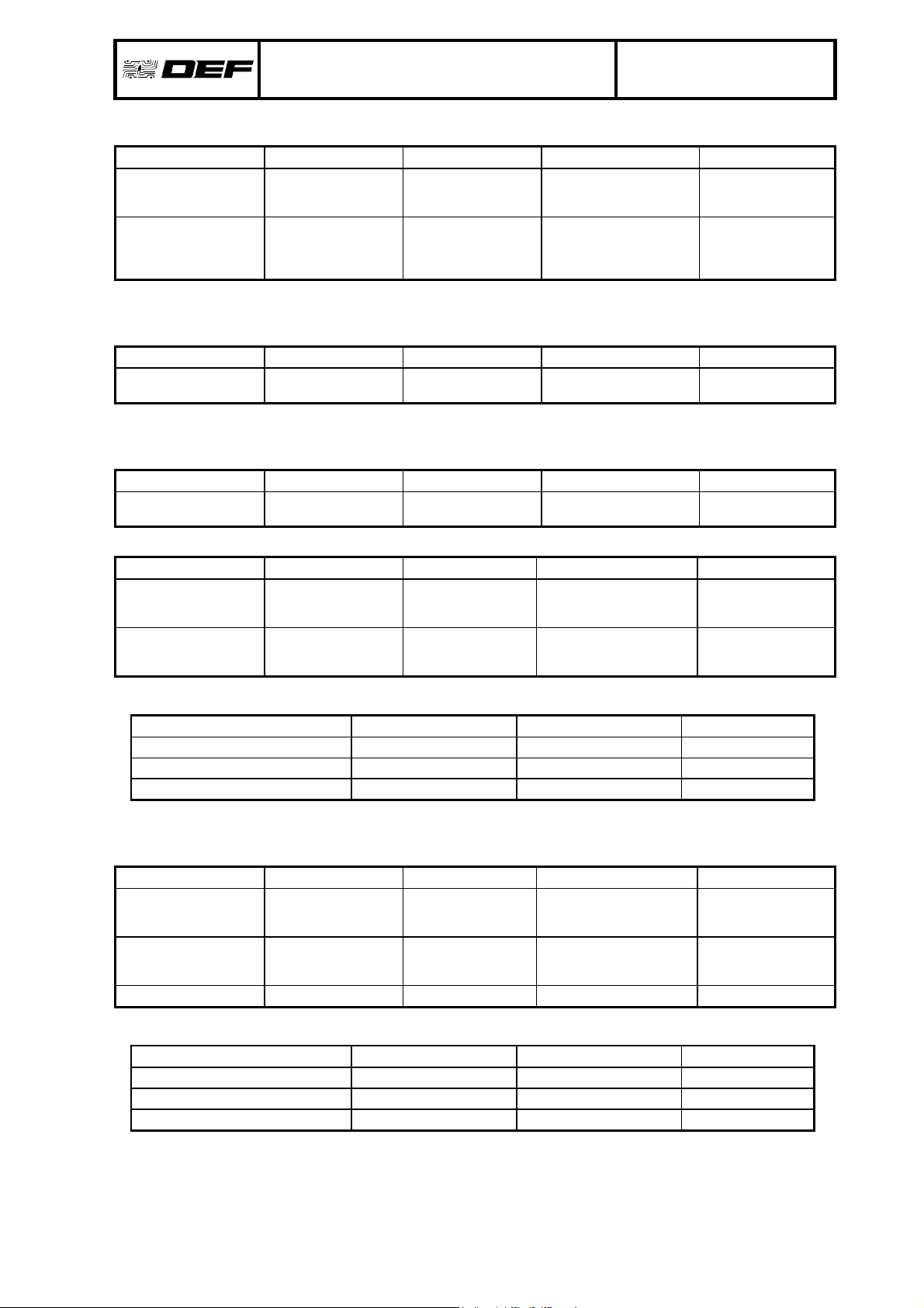
LIGNE CABLE ORIGINE MATERIEL FICHE
Réseau EDF
230V – 50Hz
NFC15-100
Section max. 2,5mm
Alimentation ALBA Sans objet A4973R
2
C.2. FACE AVANT ALTES (3U)
LIGNE CABLE ORIGINE MATERIEL FICHE
Alimentation Voie 1 1 paire 8/10° sous
écran type SYT1
Alimentation Voie 2 1 paire 8/10° sous
écran type SYT1
Dialogue Voie 1 1 paire 8/10° sous
écran type SYT1
Dialogue Voie 2 1 paire 8/10° sous
écran type SYT1
Carte CPUB ou
EAE externe
Carte CPUB ou
EAE externe
Carte CPUB ALTES (3U) A4055R
Carte CPUB ALTES (3U) A4055R
ALTES (3U) A4055R
ALTES (3U) A4055R
C.3. MODULE AR2_3U (OPTION CMSI)
LIGNE CABLE ORIGINE MATERIEL FICHE
Alimentation
Défaut secteur / batterie
≥2x8/10
ou nappé spécifique
pour ACS24-2A
EAE AR2_3U A5239R
Ce document est la propriété exclusive de DEF, il ne doit être ni communiqué, ni reproduit sans l'accord écrit de DEF.
Document : 02.NRP.518
ALTAÏR
Indice : T
Date : 31/10/06
Page : 7
D. RACCORDEMENTS EXTERIEURS
D.1. SYSTEME DE DETECTION
LIGNE CABLE ORIGINE MATERIEL FICHE
Principale 1 paire 8/10° Carte CG4L Ligne de détection A3420R
avec écran (CG4L, CGDI/DO)
sans écran (CGDI/DO)
type SYT1
Secondaire 1 paire 8/10° MBASV(Ex) Ligne de détection A3890R
avec ou sous
écran type SYT1
Alimentation 24V/0,25A 1 paire 8/10° Carte CPUB Tableau de répétition Autres A4974R
ou CGDI Isolateur A4724R
ou CGDO Détecteur ponctuel A3401R, A5604R, F515R
Détecteur multiponctuel A4134R
Détecteur linéaire A3718R, A3938R,
A3934R, A5776R
Déclencheur manuel A3402R
Alarme technique A3404R
A3926R, A3927R
Détecteur multiponctuel A5501R
MBASV(Ex) A3890R
Carte CG4L-S ligne de détection A3420R
Gamme Sirius A3076R, A3080R
Détecteur multiponctuel A4134R
Détecteur linéaire A3718R
Détecteur ponctuel A2984R, A2988R
Déclencheur manuel A2986R
Détecteur linéaire A3915R
Détecteur intrinsèque A3921R, FA289R
Détecteur multiponctuel A 5502 R
Détecteur Orion conventionnel FA485R
Orion-S conventionnelle A1750R
Solarion Conventionnelle A5776R
D.2. SYSTEME DE REPETITION
LIGNE CABLE ORIGINE MATERIEL FICHE
Répétitions Programmables 1 paire 8/10° Carte C20R Tableau de répétition
Autres
A3423R
D.3. SYSTEME D’ENTREES PROGRAMMABLES
LIGNE CABLE ORIGINE MATERIEL FICHE
Entrées programmables 1 à 4 1 paire 8/10° Carte CPUB Contacts techniques
Autres
A4974R
D.4. SYSTEME DE REPETITION GENERALE
LIGNE CABLE ORIGINE MATERIEL FICHE
Alarme Feu Générale 1 paire 8/10° Carte CPUB Tableau de répétition
Autres
Dérangement général 1 paire 8/10° Carte CPUB Tableau de répétition
Autres
Ligne de sauvegarde (*) 1 paire 8/10° Carte MCUB Répétiteur DFRA A3824R
(*) exclusivement sur MCUB
A4974R et
A5647R
A4974R et
A5647R
Ce document est la propriété exclusive de DEF, il ne doit être ni communiqué, ni reproduit sans l'accord écrit de DEF.
D.5. SYSTEME D’EVACUATION
LIGNE CABLE ORIGINE MATERIEL FICHE
Contacts auxiliaires
Diffuseurs sonores
(sortie surveillée)
Système de sonorisation de
sécurité
≥2x8/10
CR1 : 2x1,5mm
minimum
CR1 : 2x1,5mm
minimum
ALTAÏR
2
Carte AR2_3U ou
Carte X4EVAC
2
Carte AR2_3U ou
Carte X4EVAC
Document : 02.NRP.518
Indice : T
Date : 31/10/06
Page : 8
AR2_3U Contacts techniques
Autres
AVSU
AVSU-PZ
AVSU-EFP
AVS2000
AVAGS
AVAGS-ALT
SEV
Tout constructeur A5239R & A4787R
A5239R
A5239R & A4261R
A5239R & A5120R
Ce document est la propriété exclusive de DEF, il ne doit être ni communiqué, ni reproduit sans l'accord écrit de DEF.
ALTAÏR
D.6. SYSTEME D’EXPLOITATION
LIGNE CABLE ORIGINE MATERIEL FICHE
Liaison RS232
(1 liaison série)
Liaison RS422
(2 liaisons série)
D.7. DISPOSITIF DE SAUVEGARDE DE L'ALARME
Ces raccordements sont nécessaires dans le cas d'un ALTAÏR équipé à plus de 512 points. Ce dispositif est
applicable avec une face avant ALTES S (3U) exclusivement.
LIGNE CABLE ORIGINE MATERIEL FICHE
Liaison ALARME 1 paire 8/10° sous
D.8. FONCTIONS A RUPTURE
Ces fonctions sont uniquement associables à ALTES C-3U/I. De plus, le système équipé de fonctions à
rupture ne doit pas comporter plus de 512 points. Pour la fiche A4260R, lire "AR2_3U" à la place de "MAR2".
LIGNE CABLE ORIGINE MATERIEL FICHE
Ligne à rupture
1 ou 2
2 paires 8/10° sous
écran Carte CPUB
2 paires 8/10° sous
écran type SYT1
écran
1 paire 1,5 mm
2
Carte CPUB
IE4M-B UC-ALT A4092R
AR2_3U Dispositif Actionné de
Document : 02.NRP.518
Indice : T
Date : 31/10/06
Page : 9
Imprimante série
Visu série
Autres
Equipement de gestion
centralisée ou un CMSI
apte à recevoir des
informations en série
Sécurité
A3407R
A4974R
A5239R & A4260R
D.9. TABLEAU DE REPETITION D'ALARME ALTRA
LIGNE CABLE ORIGINE MATERIEL FICHE
alimentation 1 paire 8/10° sous
écran
dialogue 1 paire 8/10° sous
écran
alimentation
ou CPUB
ou ALTES (3U)
ALTES (3U) ou
CPUB ou ALTRA
précédent
Le nombre de tableaux ALTRA connectés à la sortie alimentation ALTES (3U) est limité, compte tenu de sa
capacité en courant :
ALTES S (-3U) ALTES C-3U/I ALTRA
Nombre d'éléments max. 2 X 1
Nombre d'éléments max. 0 1 2
Nombre d'éléments max. 1 X 2
Nota : au delà, utiliser une alimentation spécifique. Le nombre maximum d’ALTRA alimentés par une
alimentation extérieure est de 10.
D.10. TABLEAU DE REPETITION AGES
LIGNE CABLE ORIGINE MATERIEL FICHE
alimentation 2 x 1,5 mm² minimum
CR1 si l'entrée UGA est
utilisée
dialogue 1 paire 8/10° sous
écran
UGA 2 x 1,5 mm² minimum AR2_3U AGES A5448R
Le nombre de tableaux AGES connectés à la sortie alimentation ALTES (3U) est limité, compte tenu de sa
capacité en courant :
Nombre d'éléments max. 2 X 2
Nombre d'éléments max. 0 1 3
Nombre d'éléments max. 1 X 3
Nota : au delà, utiliser une alimentation spécifique. Le nombre maximum d’AGES alimentés par une
alimentation extérieure est de 10.
alimentation
ou CPUB
ou ALTES (3U)
ALTES (3U) ou
CPUB ou ALTRA
précédent
ALTES S (-3U) ALTES C-3U/I AGES
ALTRA A4069R,
A4070R
A3516R
ALTRA A3517R,
A4071R,
A5453R
AGES A5448R
AGES A5448R
Ce document est la propriété exclusive de DEF, il ne doit être ni communiqué, ni reproduit sans l'accord écrit de DEF.

ALTAÏR
D.11. TABLEAU RELAYAGE D'EXTINCTION
LIGNE CABLE ORIGINE MATERIEL FICHE
Report -> coffret de
relayage d'extinction
2 paire 8/10° sous
écran type SYT1
Socle Véga à Relais
ou C20R
Document : 02.NRP.518
Indice : T
Date : 31/10/06
Page : 10
Coffret de relayage
d'extinction
A 5616 R
Ce document est la propriété exclusive de DEF, il ne doit être ni communiqué, ni reproduit sans l'accord écrit de DEF.
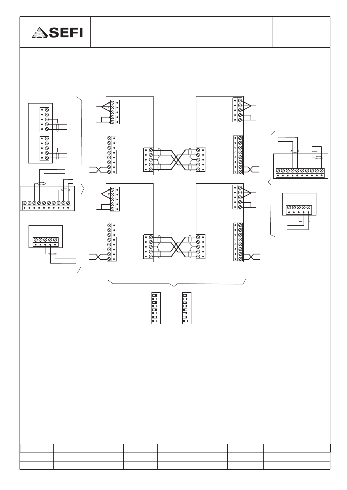
FICHE TECHNIQUE DE RACCORDEMENT
PSEUDO-MODEM
CONNECTION DATA SHEET FOR
PSEUDO-MODEM
N° PLAN
Indice
Date
Page
: A 5453 R
:A
: 09/03/04
: 1/1
CPUB
24V1
0V1
Ecr
V1V1+
24V2
0V2
Ecr
V2V2+
ALTES
V1-V1+ Ecr V1- V1+
ALTRA
E- E+ Ecr M- M+
B6B
BB6
ou/or
V2-V2+ Ecr V2- V2+
ou/or
B1
GND
+DC
-DC
GND
COM
GND
+DC
-DC
GND
COM
AC
AC
RD
TD
R+
AC
AC
RD
TD
R+
230V~
ou/or
24V=
+
-
V1
Modem
T+
TR-
T+
TR-
V1
Modem
230V~
V2
Modem
-
+
ou/or
24V=
-
+
ALTES
V1-V1+ Ecr V1- V1+
ALTRA
E- E+ Ecr M- M+
-
V1
+
Modem
V2
Modem
+
-
V2-V2+ Ecr V2- V2+
Ou/et
Or/And
B1
230V~
ou/or
-
+
-
+
-
V1
+
V1
V2
24V=
V1
-
+
-
+
V2
230V~
ou/or
24V=
V2
-
+
V1
+
AC
AC
GND
+DC
-DC
PSEUDO_MODEM
GND
RD
TD
COM
T+
TRR+
AC
AC
GND
+DC
-DC
PSEUDO_MODEM
GND
RD
TD
COM
T+
TRR+
R+
R-
GND
T-
T+
R+
R-
GND
T-
T+
UP
UP
PSEUDO_MODEM
UP
R+
RGND
TT+
PSEUDO_MODEM
UP
R+
RGND
TT+
Emission
Fonction
Date & Visa
Les liaisons dialogues sont effectuées en câble paire torsadée 8/10ième SYT1
Pour unALTRA seule, la voie de dialogue V2 n'est pas utilisée.
La distance entre la CPUB, l’ALTES, L’ALTRA et le modem doit être de 550 m maximum.
La distance entre deux modems doit être de 6km maximum
JMA.
Dessinateur
Ce plan est notre propriété, il ne peut être reproduit ou communiqué sans notre autorisation.
Vérification
Fonction
Date & Visa
SW1
on
G.S.
Chef de projet
SW2
on
ST4=ON
ST5=ON
ST6 = OFF
ST7 = OFF
ST8 = OFF
ST17 = 2-3
ST18 = OFF
Approbation
Fonction
F.C.
Dirreteur technique
Date & Visa
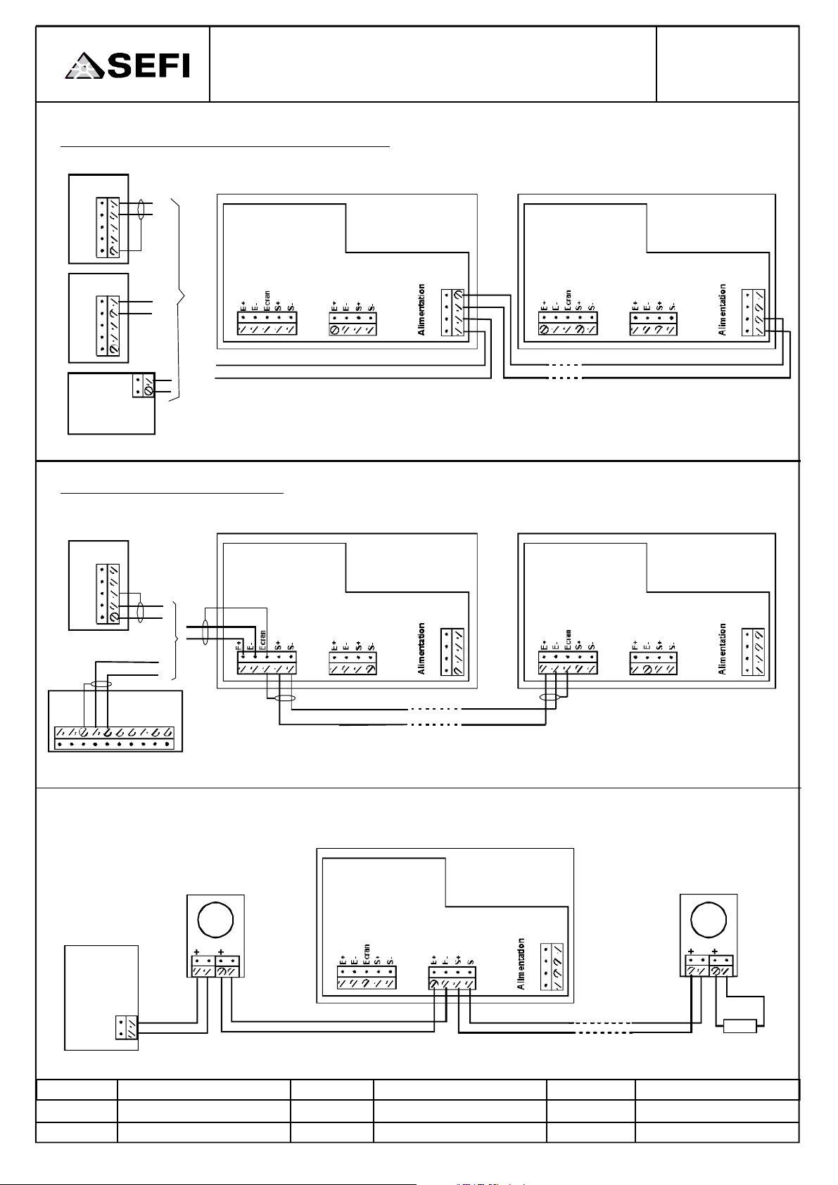
FICHETECHNIQUEDERACCORDEMENTAGES
CONNECTIONDATASHEETFORAGES
ALIMENTATIONOBLIGATOIRE/NECESSARYPOWERSUPPLY
CPUB
B6
24V1
0V1
Ecr
V1V1+
ALTES
B2
24V1
0VV1
Ecr
24V1
0VV2
Alimentation
18-60v
/18-60V
Powersupply
ou/or
ou/or
+
-
+
-
AGESN°1
+
-
+
+
-
-
B1
B2
N°PLAN
Indice
Date
Page
:A5448R
:A
:21/10/03
:1/1
AGESN°n
B4
S-
S+
E-
E+
B1
B2
B4
S-
S+
E-
E+
DIALOGUEAVECECS/DIALOGWITHCIE
CPUB
24V1
0V1
Ecr
V1V1+
ALTES
V1-V1+EcrV1-V1+
B6
ou/or
V2-V2+EcrV2-V2+
-
+
-
+
-
+
AGESN°1
B1
B2
LIAISONAVECCMSI/CONNEXIONWITHSOUNDEROUTPUT
AGES
AGESN°n
B4
S-
S+
E-
E+
B1
B2
B4
S-
S+
E-
E+
CMSI
Sirène
/Sounder
Emission
Fonction
Date&Visa
+
-
M.K.
Dessinateur
--- -
Vérification
Fonction
B1
G.S.
Chefdeprojet
UGA
B2
Date&Visa
B4
S-
S+
E-
E+
VersAGESousirène
/ToAGESorsounder
Approbation
Fonction
Date&Visa
F.C.
Dirreteurtechnique
Ceplanestnotrepropriété,ilnepeutêtrereproduitoucommuniquésansnotreautorisation.
RFL/EOL
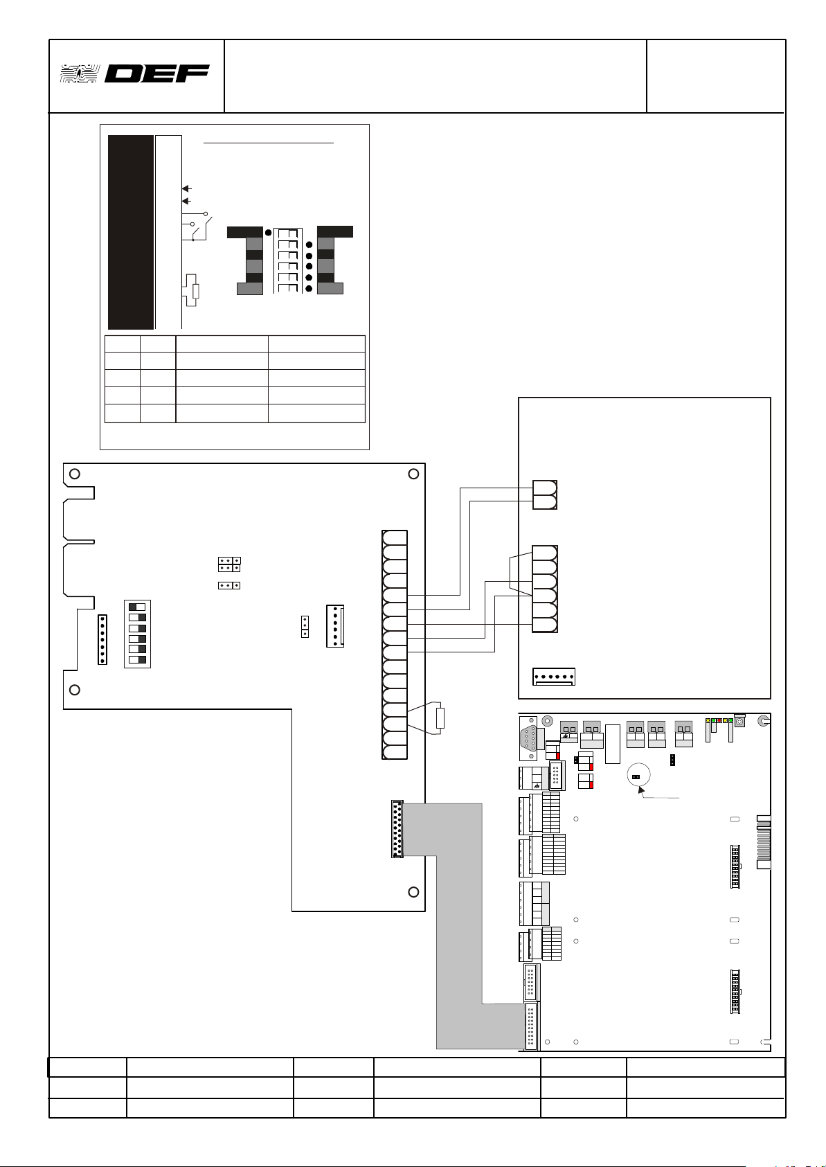
FICHE TECHNIQUE DE RACCORDEMENT
MODULE AR2-3U
N° PLAN
Indice
Date
Page
: A 5239 R
: A
: 29/01/03
: 1/1
B1
+ DAS1
- DAS1
+ DAS2
- DAS2
+ AES
- AES
DB. AES
DS. AES
Com. AES
R. Aux
T. Aux.
L. Aux.
Sirène
+ AL. EXT.
- AL. EXT.
SW3 SW4 DAS1(B1-1 et B1-2) DAS2 (B1-3 et B1-4)
"ALIM" "ALIM" Rupture 24VDC/0,5A Rupture 24VDC/0,5A
"ALIM"
"C_SEC"
"C_SEC" "C_SEC" Contact sec/1,0A Contact sec/1,0A
Remarque 1: Chaque sortie de DAS est équipée d'une diode antiretour.
Remarque 2 : Contact sec polarisé par diode (tension max = 57vd c).
10
11
12
13
{
14
15
16
"C_SEC" Contact sec/1,0A Rupture 24VDC/0,5A
"ALIM" Rupture 24VDC/1,0A Contact sec/1,0A
Module CMSI/UGA : AR2-3U
1
2
3
4
5
6
7
8
9
SW1-6 : Ligne diffuseur sonore.
SW1-2 : Durée de maintien des DAS.
SW4-5 : Type de contact pour la prise en
compte des défauts DB et DS.
+24VDC
Inversion de
polarité
Inv. Pol.
Fermé
5'
RFL
1KW
1W
La configuration de SW1 est valide juste
après l'appuie sur le bouton "RAZ"
SW1
B
D
F
H G
N.C.
Sans
Inversion
Directe
A
Ouvert
C
E
15'
N.C.
AR2-3U
(*) Sur ACS24-2A les connexions par des fils
peuvent être remplacés par un nappé spécifique
entre B5 (ACS24-2A) et B2 (AR2-3U)
+24V
0V
+DAS1
SW3 DAS2
1 2 3
ALIM
SW1
1
J2
SW4 DAS1
C-SEC
AES
B2
SW2
AL ext
1
Com AES
14
- DAS1
+DAS2
-DAS2
+AES
-AES
DB AES
DS AES
R Aux
T Aux
L Aux
13
+AL Ext
-AL Ext
1
2
3
4
5
6
7
8
9
10
Contact
11
Auxiliaire
}
12
13
Sirène
14
15
16
B1
20
J1
1
RFL
L
R
T
L
R
T
B5 (*)
Défaut
Secteur
}
Défaut
Batterie
}
EAE 24V
Pile
ST1
Uniquement sur CPUB/0
Only on CPUB/0
Emission
Fonction
Date & Visa
M.K.
Dessinateur
Ce plan est notre propriété, il ne peut être reproduit ou communiqué sans notre autorisation.
Vérification
Fonction
Date & Visa
G.S.
Chef de projet
J5
Approbation
Fonction
Date & Visa
CPUB
F.C.
Directeur technique
FICHE TECHNIQUE DE RACCORDEMENT SEV
CONNECTION DATA SHEET ”Voice Evacuation Sounder”
BORNIER DU SEV / SEV connector
N° PLAN
Indice
Date
Page
: A 5120 R
: B
: 20/02/04
: 1/1
1 2 3 4 5 6 7 8 9 10
Alimentation SEV/Power supply +
(20,4 à/to 57,6 Vcc -
Sortie UGA du tableau +
/Sounder output of the panel -
12
11
-
+
Synchronisation
Résistance de fin de ligne / End of line resistor
Relais de défaut : contact commun / Fault relay : common
Relais de défaut : contact Travail ou résistance de fin de ligne
Sortie ligne Hauts parleurs (pas de polarité)
/Loudspeaker line (not polarised)
/Fault relay : normaly close or end of line resistor
Relais de défaut : contact Repos / Fault relay : normaly open
Cas 1 : UGA avec tension de veille et d'alarme de même polarité (exemple avec 3 SEV)
/Case 1 : Sounder output with same polarity for standby and alarm signal (as example with 3 SEV)
SEV
de tête
/first SEV
J21
J25 - J26
J23 - J24
J18
J17
J19
J20
J22
J18
SEV
intermédiaire
/SEV
intermediate
109843
J17
J19
J21
J20
J22
J25 - J26
J23 - J24
109843 109843
SEV
/last SEV
de fin
J18
J17
J19
J21
J20
J22
J25 - J26
J23 - J24
+ UGA
ER
ER
- UGA
RFL/EOL
ER
ER : Elément
de raccordement
type Domino
/junction block
Cas 2 : UGA avec tension de veille et d'alarme de polarité inversée (exemple avec 3 SEV)
/Case 2 : Sounder output with inverted polarity for standby and alarm signal (as example with 3 SEV)
SEV
de tête
/first SEV
J21
J20
J22
J25 - J26
J23 - J24
J18
J17
J19
SEV
intermédiaire
/SEV
intermediate
109843
J25 - J26
J23 - J24
J18
J17
J19
J21
J20
J22
109843 109843
SEV
de fin
/last SEV
J25 - J26
J23 - J24
+ UGA
(*)
ER
ER
- UGA
(*) Polarité pour la surveillance (position de veille). Elle est inversée en commande
(*) Polarity for control (standby position). It is inverted on command
Montage dans le même coffret / to assemble in the same box
Emission
Fonction
Date & Visa
M.K.
Dessinateur
Ce plan est notre propriété, il ne peut être reproduit ou communiqué sans notre autorisation.
Vérification
Fonction
Date & Visa
G.S.
Chef de projet
Approbation
Fonction
Date & Visa
J18
J17
J19
J21
J20
J22
RFL/EOL
F.C.
Directeur technique
FICHETECHNIQUEDERACCORDEMENT
“CPUB”
L2
L1L3L4L5
N°PLAN
Indice
Date
Page
Reset
:A4974R
:B
29/01/03
:1/1
FU100
BP1
PDL
-L
Alarmdevice
Aux.24Vout2
FLASH
SW3
+L
ES
HS
PDL-HMI
Progr.
Norm.
Eprom
Flash
24V2
0V2
Shield
V2-
V2+
IN2+
IN2Shield
OUT2+
OUT2-
/Tel.DDS
B5
TX
RX
BB6
BB7
HMI1 HMI2
24V1
0V1
Shield
V1-
V1+
JBUS1 JBUS2
IN1+
IN1-
Shield
OUT1+
OUT1-
B6
B7
+U-U
Aux.
24Voutput
+B-B
Battery
1A
2A
UniquementsurCPUB/0
OnlyonCPUB/0
Main
power
+V-V
B8
NC
COM
NO
NC
COM
NO
BB9
INPUT INPUT
E3+
E1+
E3-
E1-
E4+
E2+
E4-
E2-
B9
Emission
Fonction
Date&Visa
M.K.
Dessinateur
Vérification
Fonction
Date&Visa
G.S.
Chefdeprojet
Approbation
Fonction
Date&Visa
F.C.
DirecteurTechnique
CedocumentestlapropriétéexclusivedeDEF,ilnedoitêtrenicommuniqué,nireproduitsansl'accordécritdeDEF.
N°PLAN
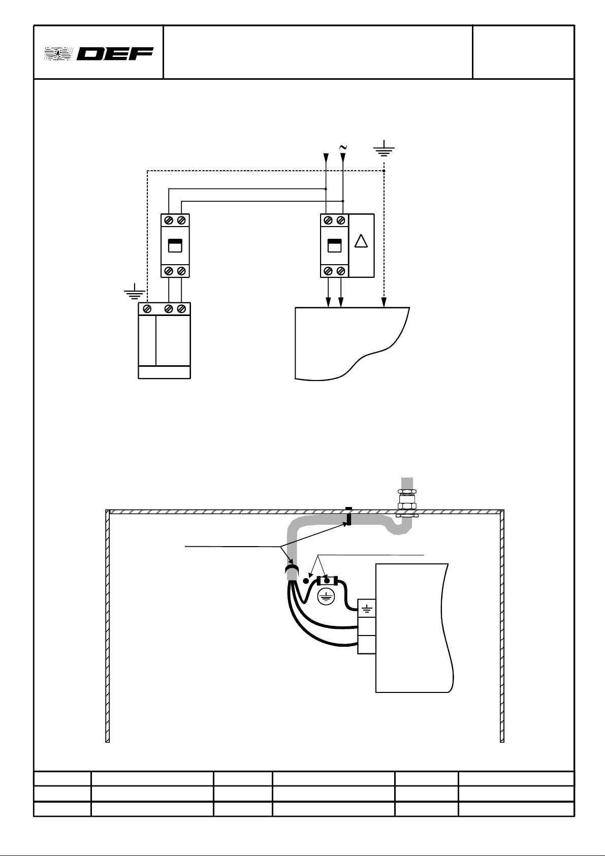
FICHETECHNIQUEDERACCORDEMENTSECTEUR
CONNECTIONDATASHEETMAINSPOWERSUPPLY
Indice
Date
Page
CONNEXIONSAURESEAUETPROTECTIONS/CONNECTIONSTOMAINSANDFUSES
Réseau/
Mains
230V
:A4973R
:A
:11/02/02
:1/1
L1
Disjoncteur20A
omnipolaire
(06469Legrand)
20Aall-pole
circuit-breaker
(06469Legrand)
L2
Parafoudre
(03822Legrand)
Lightningarrester
(03822Legrand)
30mA
Longueurmini5m
Minlength5m
CHASSIS/BASE
Disjoncteurdifférentiel30mA
avecprotection6A
30mAdifferentialcircuit-braker
with6Afuse(07860Legrand).
(07860Legrand).
Nota:Lesréférencessontdonnéesàtitreindicatif.
Thereferencesareonlyforinformation.
RACCORDEMENTSECTEURETMISEALATERRE/MAINSCONNECTIONANDGROUND
Emission
Fonction
Date&Visa
Tenueducâbleparcollier/
“Tirap”typecablesealto
holdcableinplace
Nota:Lefilderaccordementdeterredoitêtredelongueursupérieureaux2autres(sécuritéélectrique).
Theearthwirehavetobelongerthanthetwoothers(electricalsafety)
M.K.
Dessinateur
Vérification
Fonction
G.S.
Chefdeprojet
Date&Visa
CedocumentestlapropriétéexclusivedeDEF,ilnedoitêtrenicommuniqué,nireproduitsansl'accordécritdeDEF.
Goujonschassis/Earthpoints
ALIMENTATION/
POWERSUPPLY
N
Ph
Approbation
Fonction
Date&Visa
F.C.
DirecteurTechnique
DETECTEUR
DETECTOR
FICHETECHNIQUEDERACCORDEMENT"MIV+"
CONNECTIONDATASHEETFOR"MIV+"
Ec
N°PLAN
Indice
Date
Page
LigneD.I.Système
Bouclé
Ec
LineD.I.looped
system
:A4724R
:B
:08/11/01
:1/1
Ec=Screen
B2
321
Ec-+
B1
54321
-+Ec-+
CIV+
Emission
Fonction
Date&Visa
ThedocumentistheexclusivepropertyofDEF.CommunicationandreproductionprohibitedwithoutthewrittenpermissionofDEF
M.K.
Dessinateur
CedocumentestlapropriétéexclusivedeDEF,ilnedoitêtrenicommuniqué,nireproduitsansl'accordécritdeDEF.
Vérification
Fonction
Date&Visa
C.B.
Chefdeprojet
Approbation
Fonction
Date&Visa
F.C.
ResponsableR&D
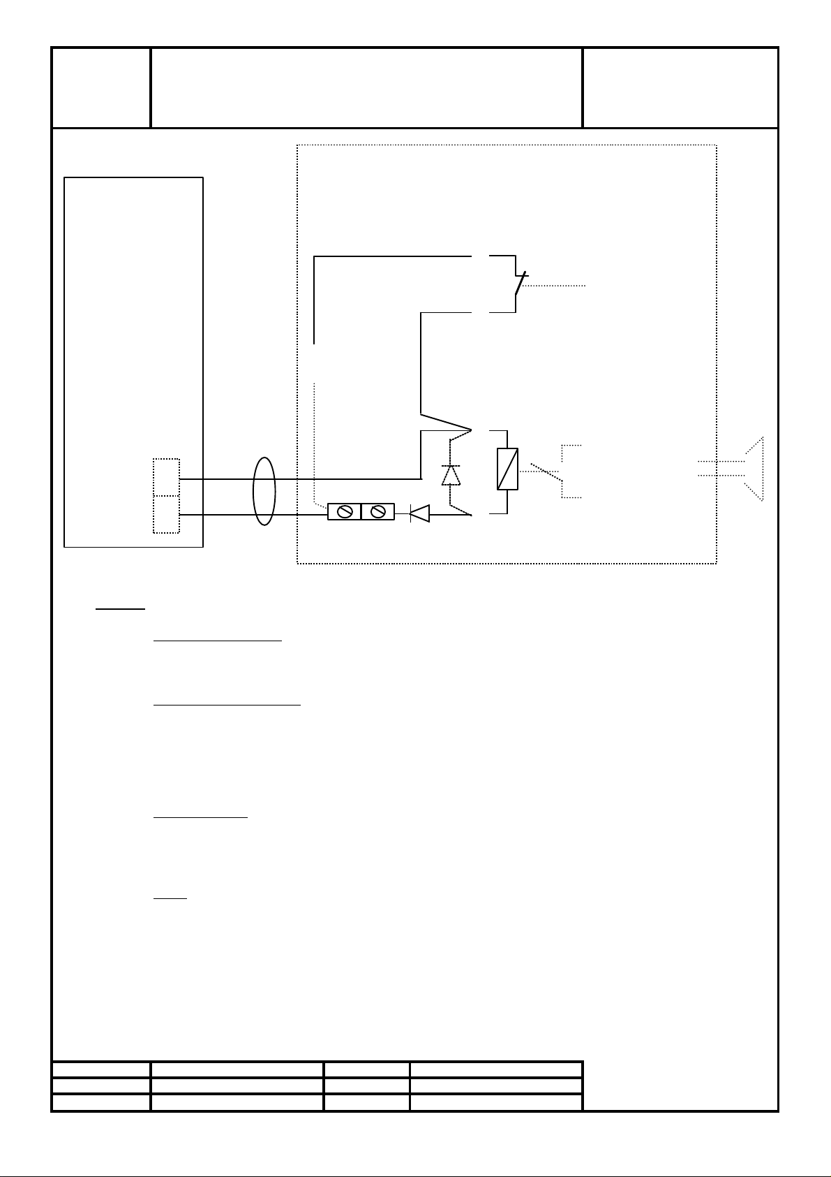
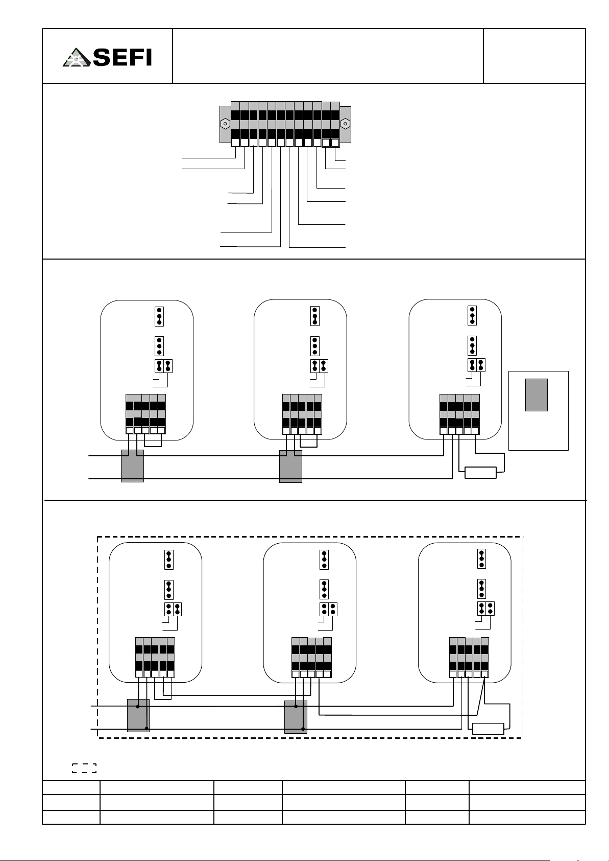
Fiche technique de raccordement
des Systèmes de sonorisation de sécurité
NOTA :
Révision
GS
Approbation
TM
Fonction
Chef de projet
Fonction
Resp. M&I
Ce plan est notre propriété, il ne peut être reproduit ou communiqué sans notre autorisation.
SEFI
RFL
D
D
CMSI
N° PLAN : A4787R
Indice : B
Date : 08/04/2003
Page : 1/1
SYSTEME DE
SONORISATION
DE SECURITE
Report
dérangement
Câble
+
Commande
évacuation
Sortie DS
-
Domino
les repères +, - indiquent la tension en commande du CMSI
Tension de sortie du CMSI :
fonctionnement en 48 VCC: Un = 48 VCC, Umin = 43,2 VCC, Umax = 57,6 VCC
fonctionnement en 24 VCC: Un = 24 VCC, Umin = 21,6 VCC, Umax = 28,8 VCC
Entrée de commande du S.S.S:
relais de commande 48 VCC ou 24VCC selon version, interne au système de sonorisation
Sortie dérangement du S.S.S:
contact fermé lorsque le S.S.S est en fonctionnement normal
contact ouvert lorsque le S.S.S est en dérangement
Matériel nécessaire:
1 Résistance de Fin de Ligne: RFL selon la ligne de diffuseurs sonores utilisée
2 diode D: 1N4004.
1 domino
Câble:
2 conducteurs Ø = 0,8 mm ou 0,9 mm . Sans écran.Type : CR1
Date & Visa Date & Visa

FICHETECHNIQUEDERACCORDEMENT
TABLEAUREPETITEURSTAR
N°PLAN
Indice
Date
CONNECTIONDATASHEETSTARREMOTEPANEL
Page
RACCORDEMENT/CONNECTION
TYPEDECÂBLESAUTILISER:Nx1pairetéléphonique8/10èmesousécran.Leraccordements'effectueselonleschémasuivant:
CABLETYPETOUSE:Nx1paircableToconnectaccordingtotheschemabelow.8/10èmeunderscreen.
-e-----------
CarteCSS
NC
NC
+Défautdesécurité/
-Safetyfault
+Miseensécurité/
+
Alimentation
Powersupply
-
-Safetyprocesscontrol
+Défautd'attente/
-Standbyfault
+DérangementCMSI/
-FSCEfault
RépétitionsCMSI/
FSCERepetitions
(ModéleSTAR-C)
:A4408R
:B
:08/01/02
:1/1
+
Lignesurveillée/
Controlledline
RFL/LTR
+DérangementSDI/
-CIEfault
+Alarme
+Alarmefeu/
-Feualarm
Ecran/
Screen
-
+Veille
+Veillerestreinte/
-Restrictedstandby
+Défaut
+Défautliaison/
-Connectionfault
+Evacuation
+Evacuationgénérale/
-Generalevacuation
+
Alarme/Alarm
-
RépétitionSDI/
CIErepetition
(ModèlesSTAR-DI,-A,-C)
TableauDICMSI/
FSCE-CIEpanel
RFL=LTR=2,2k1/4W
RA=5601/4W
RépétitionsUGA/
AMUrepetition
(ModeleSTAR-A,-C)
+
Lignesurveillée/
Controlledline
RA
-
RFL/LTR
contactNO
(NormalementOuvert/
NormallyOpen)
Toconnectonrelaywhichcanbyconfigured
Emission
Fonction
Date&Visa
R/T
RA
Reprisesurcontactsconfigurables/
M.K.
Dessinateur
C
L
Vérification
Fonction
C.B.
Chefdeprojet
(NF)
(NC)
ReprisedecontactsurlerelaisRLT/
ToconnectonrelayNO/NC
Date&Visa
CedocumentestlapropriétéexclusivedeDEF,ilnedoitêtrenicommuniqué,nireproduitsansl'accordécritdeDEF.
ThisdocumentistheexclusivepropertyofDEF.Communicationandreproductionprohibitedwithoutwrittenauthorization
L
C
Approbation
Fonction
Date&Visa
(NO)
F.C.
DirecteurTechnique

FICHETECHNIQUEDERACCORDEMENT"SYSTEMED'EVACUATION"
CONNECTIONDATASHEETFOR"EVACUATIONSYSTEM"
Diffuseuréquipéd'unbornierà5points(type1)
Sounderwithterminalblockof5points(type1)
+
-
Lignedediffuseurs
sonores
SounderLine
1 32 4 5
N°PLAN
Indice
Date
Page
1 32 4 5
:A4261R
:D
:24/10/01
:1/1
RFL/LTR
E+ E- S+ S-
-
Diffuseurintermédiaire
Intermediatesounder
Diffuseuréquipéd'unbornierà4points(type1)
Sounderwithterminalblockof4points(type1)
+
-
Lignedediffuseurs
sonores
SounderLine
1 32 4
E+ E- S+ S-
-
Dernierdiffuseur
Lastsounder
RFL:Résistancedefindeligne
LTR:Lineterminalresitor
RFL/LTR
1 32 4
Emission
Fonction
Date&Visa
Diffuseurintermédiaire
Intermediatesounder
M.K.
Dessinateur
CedocumentestlapropriétéexclusivedeDEF,ilnedoitêtrenicommuniqué,nireproduitsansl'accordécritdeDEF.
Vérification
Fonction
Date&Visa
F.P.
Chefdeprojet
Approbation
Fonction
Date&Visa
Dernierdiffuseur
Lastsounder
F.C.
ResponsableR&D

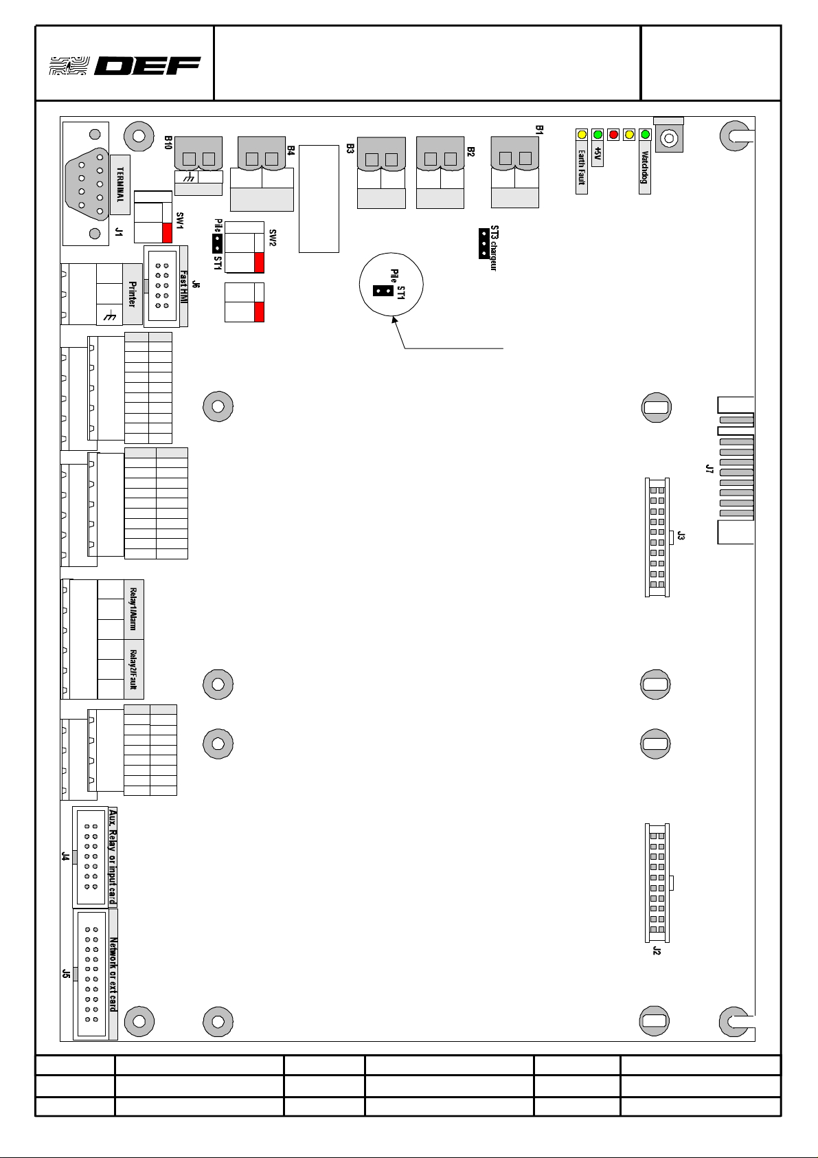
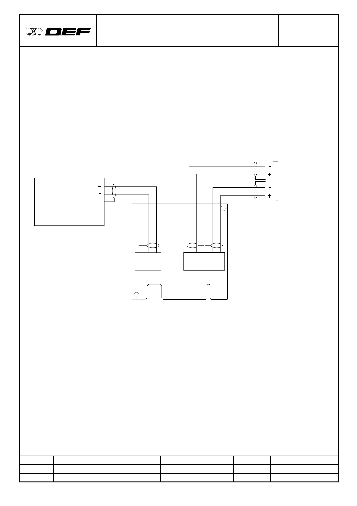
FICHETECHNIQUEDERACCORDEMENT“D.A.S.SurMAR2”
CONNECTIONDATASHEET“D.A.S.ONMAR2”
DRGW#
Indice
Date
Page
:A4260R
:C
:19/09/02
:1/1
SortieDASconfiguréeenalimentationinterne(selonpositionSW3etSw4)
DASoutputconfiguredininternalpowersupply(dependingonSW3andSW4position)
DASn°1
ModuleMAR2
+DASn
24Vinterne
/internal
-DASn
SortieDASconfiguréeencontactsec(selonpositionSW3etSw4)
DASoutputconfiguredinfreecontact(dependingonSw3andSw4position)
DASn°1
DASn°n
DASn°n
Alimentation
/Powersupply
24Vou48V
1A
ModuleMAR2
+DASn
+
-
-DASn
Nejamaisraccorderd'alimentation48VàB1-15etB1-16ouoduleMAR2
Neverconnect48Von
Release
Function
Date/Stamp
M.K.
Designer
Cedocumentestnotrepropriétéexclusive,ilnedoitêtrenicommuniqué,nireproduitsansnotreaccordécrit.
Thisdocumentisourexclusiveproperty,disseminationandreproductionprohibitedwithoutourwrittenapprovalforallcountries.
B1-15andB1-16orB1-5andB1-6ofMAR2module
Inspection
Function
Date/Stamp
F.P.
ProjectManager
B1-5etB1-6dum
Approval
Function
Date/Stamp
T.M.
M&IManager

Vers
tableau
deDI
FICHETECHNIQUEDERACCORDEMENT"EOLE4A"
CONNECTIONDATASHEETFOR"EOLE4A"
ToDI
panel
+
L
-
10
11
12
13
14
15
16
17
18
19
20
21
22
23
24
1
L1+
2
L1e
3
4
L2+
L2-
5
e
6
IND1-
7
IND2-
8
IND+
9
IND3IND4IND+
IND5IND6IND+
IND7IND8IND+
DB+
DBe
DS+
DSe
10
11
12
13
14
15
16
17
18
19
20
21
22
23
24
1
L1+
2
L1e
3
4
L2+
L2-
5
e
6
IND1-
7
IND2-
8
IND+
9
IND3IND4IND+
IND5IND6IND+
IND7IND8IND+
DB+
DBe
DS+
DSe
N°PLAN
Indice
Date
Page
:A4134R
:B
:29/10/01
:1/1
EOLE4AN°1
RACCORDEMENTDESEOLE4A
(Avec1indicateurd'actionpardétecteurSIAMouSOAM)
CONNECTIONOFEOLE4ASYSTEMS
(With1remoteindicatorperSIAMorSOAMdetector)
Vers
tableau
deDI
panel
ToDI
+
L
-
10
11
12
13
14
15
16
17
18
19
20
21
22
23
24
1
2
3
4
5
6
7
8
9
L1+
L1-
e
L2+
L2-
e
IND1IND2-
IND+
IND3IND4-
IND+
IND5IND6-
IND+
IND7IND8-
IND+
DB+
DB-
e
DS+
DS-
e
-
IA1
+
-
IA2
+
-
IA3
+
-
IA4
+
-
IA5
+
-
IA6
+
-
IA7
+
-
IA8
+
EOLE4A
Nota:IA=Indicateurd'action
IA=RemoteIndicator
EOLE4AN°2
RACCORDEMENTDESEOLE4A
(Avec1indicateurd'actioncommun)
CONNECTIONOFEOLE4ASYSTEMS
(With1commonremoteindicator)
Vers
tableau
deDI
ToDI
panel
L1
L2
+
-
+
-
10
11
12
13
14
15
16
17
18
19
20
21
22
23
24
1
2
3
4
5
6
IND1-
7
IND2-
8
IND+
9
IND3IND4-
IND+
IND5IND6-
IND+
IND7IND8-
IND+
DB+
DS+
EOLE4A
L1+
L1-
e
L2+
L2-
e
DB-
e
DS-
e
-
IA
+
Emission
Fonction
Date&Visa
M.K.
Dessinateur
Vérification
Fonction
Date&Visa
CedocumentestlapropriétéexclusivedeDEF,ilnedoitêtrenicommuniqué,nireproduitsansl'accordécritdeDEF.
ThisdocumentistheexclusivepropertyofDEF.Communicationandreproductionprohibitedwithoutwrittenauthorization
C.B.
Ingénieurresponsable
Approbation
Fonction
Date&Visa
F.C.
ResponsableR&D

FICHETECHNIQUEDERACCORDEMENT
DESLIGNESDANSLECASALTAÏRPLUSDE
512POINTS-"ALTAÏR"
RELAISALARMENORMALEMENTOUVERT(SW4surL)
ATTENTION :Ceraccordement
IE4M-B
B2
COM
NF
NO
B1
n'estvalablequ'avecuneALTESS
B3
1+
1-
+
-
Câblage
-
interne
1paire9/10
2+
2-
+
ALTESS(3U)
UC-ALT(3U)
N°PLAN
Indice
Date
Page
:A4092R
:C
:08/01/02
:1/1
1paire9/10
BASALT
Câblage
interne
Versutilisation
contactalarme
générale
Relaisd'alarme
générale
B8
COM
NO
Relais
d'alarme
générale
CPUB
Ei-
Ei+
B9
programméeen
répétitionde
dérangement
Entréedereport
BB9
RELAISALARMENORMALEMENTFERME(SW4surR)
ATTENTION :Ceraccordement
IE4M-B
B2
COM
NF
NO
B1
n'estvalablequ'avecuneALTESS
B3
1+
1-
+
-
Câblage
-
interne
1paire9/10
2+
2-
+
ALTESS(3U)
UC-ALT(3U)
Emission
Fonction
Date&Visa
Câblage
interne
1paire9/10
Relaisd'alarme
générale
B8
COM
NO
Relais
d'alarme
générale
CPUB
Entréedereport
BB9
M.K.
Dessinateur
Vérification
Fonction
Date&Visa
BASALT
Versutilisation
contactalarme
générale
C.B..
Ingénieurresponsable
EiEi+
Approbation
Fonction
Date&Visa
programméeen
répétitionde
B9
dérangement
F.C.
Directeurtechnique
CedocumentestlapropriétéexclusivedeDEF,ilnedoitêtrenicommuniqué,nireproduitsansl'accordécritdeDEF.

FICHETECHNIQUEDERACCORDEMENT
"DIALOGUEALTRA-MCUBouALTRA-CPUB"
CONNECTIONDATASHEETFOR
"ALTRA-MCUB"or"ALTRA-CPUB"DIALOG
N°PLAN
Indice
Date
Page
:A4071R
:B
:10/10/01
:1/1
MCUB
ou
CPUB
B6
(MCUB)
B7
(CPUB)
V1+
Ecr
ALTRAN°1 ALTRAN°n
ALTRA#1 ALTRA#n
B1B1
E- E-
E+ E+V1-
Ecr Ecr
M+ M+
M- M-
Emission
Fonction
Date&Visa
ECR:Screen
M.K.
Dessinateur
CedocumentestlapropriétéexclusivedeDEF,ilnedoitêtrenicommuniqué,nireproduitsansl'accordécritdeDEF.
Vérification
Fonction
Date&Visa
C.B.
IngénieurResponsable
Approbation
Fonction
Date&Visa
F.C.
ResponsableR&D

MCUB
ou
CPUB
B6
(MCUB)
B7
(CPUB)
FICHETECHNIQUEDERACCORDEMENT
"ALIMENTATIONALTRA-MCUBouALTRACPUB"
CONNECTIONDATASHEETFOR
"ALTRA-MCUB"POWERSUPPLY
ALTRAN°1 ALTRAN°n
ALTRA#1 ALTRA#n
B2
N°PLAN
Indice
Date
Page
B2
:A4070R
:B
:05/10/01
:1/1
0V1 0VE 0VE
+24V1 +24VE +24VE
Ecr 0VS 0VS
+24VS +24VS
Emission
Fonction
Date&Visa
M.K.
Dessinateur
CedocumentestlapropriétéexclusivedeDEF,ilnedoitêtrenicommuniqué,nireproduitsansl'accordécritdeDEF.
Vérification
Fonction
Date&Visa
C.B.
IngénieurResponsable
Approbation
Fonction
Date&Visa
F.C.
ResponsableR&D

FICHETECHNIQUEDERACCORDEMENT
ALIMENTATIONLOCALE
Alimentation
24V
Secourue
0V
"ALIMENTATIONLOCALEALTRA"
CONNECTIONDATASHEETFOR
"ALTRA"LOCALPOWERSUPPLY
ALTRAN°1 ALTRAN°n
B2
0VE
N°PLAN
Indice
Date
Page
:A4069R
:B
:31/10/01
:1/1
B2
0VE
+24V
Contactsec
défautsecteur
(1)
Contactsec
défautbatterie
(1)
(1):Contactferméencasdedéfaut
LOCALPOWERSUPPLY
24V
batt.backed
pwrsupply
0V
+24VE
0VS
+24VS
+24VE
0VS
+24VS
B3
0V
DB
DS
ALTRA#1 ALTRA#n
B2
0VE 0VE
B2
Emission
Fonction
Date&Visa
+24V
Mainsfault
drycontact
(1)
Batteryfault
drycontact
(1)
+24VE
0VS
+24VS
B3
0V
DB
DS
(1):Closedcontactincaseoffault
M.K.
Dessinateur
Vérification
Fonction
Date&Visa
CedocumentestlapropriétéexclusivedeDEF,ilnedoitêtrenicommuniqué,nireproduitsansl'accordécritdeDEF.
C.B.
Chefdeprojet
Approbation
Fonction
Date&Visa
F.C.
ResponsableR&D
+24VE
0VS
+24VS

FICHE TECHNIQUE DE RACCORDEMENT FACE AVANT ALTES
CONNECTION DATA SHEET FOR ALTES FRONT PANEL
N° PLAN
Indice
Date
Page
: A 4055 R
: E
: 28/01/03
: 1/1
B2
+24V1
0V1
Ecran
Screen
+24V2
0V2
B1
V1-
V1+
Ecran
Screen
V1-
V1+
V2-
V2+
Ecran
Screen
V2-
V2+
+24V1
Screen
BASE : ALTES S ou
ALTES C si 512 pts max suivant normes.
BASE : ALTES S or
ALTES C up to 512 pts
B6
0V1
Ecran
V1-
V1+
+24V2
0V2
Ecran
Screen
V2-
V2+
MCUB
ou
CPUB
B2
+24V1
0V1
Ecran
Screen
+24V2
0V2
B1
V1-
V1+
Ecran
Screen
V1-
V1+
V2-
V2+
Ecran
Screen
V2-
V2+
ALTES S optionnelle
ALTES S option
(only if base is
also ALTES S)
B2
+24V1
0V1
Ecran
Screen
+24V2
0V2
B1
V1-
V1+
Ecran
Screen
V1-
V1+
V2-
V2+
Ecran
Screen
V2-
V2+
EAE24V : Equipement d’Alimentation Electrique
PSE24V : Power Supply Equipment
B6
+24V1
0V1
Ecran
Screen
V1-
V1+
+24V2
0V2
Ecran
Screen
V2-
V2+
BB6
MCUB
ou
CPUB
BASE : ALTES S ou
ALTES C si 512 pts max suivant normes.
BASE : ALTES S or
ALTES C up to 512 pts
EAE24V
PSE24V
+
U1
-
+
U2
-
ALTES S optionnelle
ALTES S option
(only if base is
also ALTES S)
B2
+24V1
0V1
Ecran
Screen
+24V2
0V2
B1
V1-
V1+
Ecran
Screen
V1-
V1+
V2-
V2+
Ecran
Screen
V2-
V2+
Emission
Fonction
Date & Visa
M.K.
Dessinateur
Vérification
Fonction
Date & Visa
G.S.
Chef de projet
Approbation
Fonction
Date & Visa
F.C.
Résponsable R & D
Ce document est la propriété exclusive de DEF, il ne doit être ni communiqué, ni reproduit sans l'accord écrit de DEF.
The document is the exclusive property of DEF. Communication and reproduction prohibited without the written permission of DEF.

FICHETECHNIQUEDERACCORDEMENTFORAV
CONNECTIONDATASHEETFORAVpourALTAÏR
N°PLAN
Indice
Date
Page
:A3938R
:B
:25/10/01
:1/1
BRANCHEMENTD'UNFORAVSUR2LIGNES24V
CONNECTIONOFONEFORAVON224V-LINES
FORAV-E
Attention
Avanttoutréglage
d'orientation,desserrer
lavisdeblocagerepérée
parduvernisrougesituée
surledessusduboîtier
FORAV-R
Attention
Avanttoutréglage
d'orientation,desserrer
lavisdeblocagerepérée
parduvernisrougesituée
surledessusduboîtier
BRANCHEMENTD'UNFORAVSUR1LIGNES24V
CONNECTIONOFONEFORAVON124V-LINE
FORAV-E
Attention
Avanttoutréglage
d'orientation,desserrer
lavisdeblocagerepérée
parduvernisrougesituée
surledessusduboîtier
FORAV-R
Attention
Avanttoutréglage
d'orientation,desserrer
lavisdeblocagerepérée
parduvernisrougesituée
surledessusduboîtier
BRANCHEMENTDE"n"FORAV-ESUR1LIGNE24V BRANCHEMENTDE"n"FORAV-RSUR1LIGNE24V
CONNECTIONOF"n"FORAV-EON124V-LINE
EMETTEURn
TRANSMITTERn
FORAV-E FORAV-E
Caution Caution
Ligne24V
24Vline
EMETTEURn+1
TRANSMITTERn+1
VersémetteurN°3
Totransmitter#3
CONNECTIONOF"n"FORAV-RON124V-LINE
RECEPTEURn RECEPTEURn+1
RECEIVERn RECEIVERn+1
FORAV-R
Caution
Ligne24V
24Vline
FORAV-R
Caution
Emission
Fonction
Date&Visa
LigneDI
DIline
Boîtierde
raccordement
Boîtierde
raccordement
Connectionbox Connectionbox
M.K
Dessinateur Ingénieurresponsable
Vérification
Fonction
C.B.
Date&Visa
Approbation
Fonction
Date&Visa
F.C.
ResponsableR&D
CedocumentestlapropriétéexclusivedeDEF,ilnedoitêtrenicommuniqué,nireproduitsansl'accordécritdeDEF.

FICHETECHNIQUEDERACCORDEMENT
EMETTEUR/RECEPTEURFORAV
CONNECTIONDATASHEETFOR
FORAVTRANSMTTER/RECEIVER
N°PLAN
Indice
Date
Page
:A3934R
:B
:25/10/01
:1/1
RECEPTEUR
RECEIVER
1 2 3 4 5 6 7 8 9 10 11 12
1paire9/10
sousécran
1-pair9/10
cable
underscreen
Verstableau
alimsecourue
Topanel
battery-backed
powersupply
câble1paire
9/10sousécran
1-pair9/10
cable
underscreen
EMETTEUR
TRANSMITTER
1 2 3 4 5 6 7 8 9 10
Verstableau
Topanel
RFL:Résistancedefindeligne.
LTR:Lineterminalresistor
RFL
LTR
1paire9/10
sousécran
1-pair9/10
cable
underscreen
Vers
tableau
ou
alimentation
secourue
Topanel
or
battery-backed
powersupply
DETAILBORNIER
RECEPTEUR
RECEIVERTERMINALBLOCK
DETAIL
1 2 3 4 5 6 7 8 9 10 11 12
Emission
Fonction
Date&Visa
M.K
Dessinateur
CedocumentestlapropriétéexclusivedeDEF,ilnedoitêtrenicommuniqué,nireproduitsansl'accordécritdeDEF.
Vérification
Fonction
Date&Visa
C.B.
ChefdeProjet
DETAILBORNIER
EMETTEUR
TRANSMITTERTERMINALBLOCK
DETAIL
1 2 3 4 5 6 7 8 9 10
Approbation
Fonction
Date&Visa
F.C.
ResponsableR&D

FICHETECHNIQUEDERACCORDEMENTGTVR
CONNECTIONDATASHEETGTVR
GTVRN°1
NO/NCSelection
SélectionNO/NF
N°PLAN
Indice
Date
Page
:A3927R
:B
:09/11/01
:1/1
Screen
Length<1km(56)
Cable9/10withscreen
Longueur<1km(56)
Ecran
Câble9/10avecécran
L+
L-
Alimentation
supplémentaire
Additional
powersupply
24V
+
-
-
1paire1,5mm²
Touslesécransdecâbledoivent
êtreprotégésparsouplisseau.
Allcablescreensmustbe
protectedbytubing
GTVRN°X
Length<10m
Longueur
<10m
Contact
"Cdemanuelle"
"Manualcontrol"
contact
NO/NCselection
SélectionNO/NF
Adisposition:
16contactslibresdetoutpotentiel
entreCTxetCRx
U<50Vdc,I<0,2A
Available:
16potential-freecontacts
betweenCTxandCRx
U<50Vdc,I<0.2A
Emission
Fonction
Date&Visa
M.K.
Dessinateur
Vérification
Fonction
Date&Visa
CedocumentestlapropriétéexclusivedeDEF,ilnedoitêtrenicommuniqué,nireproduitsansl'accordécritdeDEF.
ThisdocumentistheexclusivepropertyofDEF.Communicationandreproductionprohibitedwithoutwrittenauthorization.
C.B.
Ingénieurresponsable
Approbation
Fonction
Date&Visa
F.C.
ResponsableR&D

FICHETECHNIQUEDERACCORDEMENT"GTVE"
CONNECTIONDATASHEET"GTVE"
GTVEN°1
N°PLAN
Indice
Date
Page
:A3926R
:B
:29/10//01
:1/1
Ecran
Screen
L+
L-
Longueur<1km(56)
Câble9/10avecécran
Length<1km(56)
Cable9/10withscreen
Alimentation
supplémentaire
Additional
powersupply
24V
+
-
-
1paire1,5mm²
1pair1,5mm²
Touslesécransdecâbledoivent
êtreprotégésparsouplisseau.
Allcablescreensmustbe
protectedbytubing
GTVEN°X
E+
C
S+
e
N°1
Dérangement
prioritaire
Priorityfault
E+
C
S+
e
N°2
Dérangement
Fault
+
-
e
N°1
Alarmeprioritaire
Priorityalarm
+
-
e
N°2
Alarme
Alarm
Emission
Fonction
Date&Visa
n<8contacts
Lignesecondaire<1Km(56)
C:Plotdereport
Enrèglegénérale,l'écran
est
conseillépourune
longueur>100m.
M.K
Dessinateur
ThisdocumentistheexclusivepropertyofDEF.Communicationandreproductionprohibitedwithoutwrittenauthorization
Ceplanestnotrepropriété,ilnepeutêtrereproduitoucommuniquésansnotreautorisation.
n<8contacts
Secondaryline<1Km(56)
C:Feedbackpin
Asageneralrule,
usescreenwhenlengthline
is>100m.
RFL=Résistancefindeligne
LTR=LineTerminalResistor
Vérification
Fonction
C.B.
Ingénieurresponsable
Date&Visa
+
-
e
N°n
Alarme
Alarm
RFL
LTR
Approbation
Fonction
Date&Visa
E+
S+
Dérangement
Fault
RFL
LTR
F.C.
ResponsableR&D
C
e
N°n

FICHETECHNIQUEDERACCORDEMENT
"SYSTEMEDES.I.BZ.VIREx"
CONNECTIONDATASHEET"S.I.BZ.VIRExSYSTEM"
N°PLAN
Indice
Date
Page
:A3921R
:B
:09/11/01
:1/1
Emission
Fonction
Date&Visa
M.K.
Dessinateur
CedocumentestlapropriétéexclusivedeDEF,ilnedoitêtrenicommuniqué,nireproduitsansl'accordécritdeDEF.
Vérification
Fonction
Date&Visa
C.B.
IngénieurResponsable
Approbation
Fonction
Date&Visa
F.C.
ResponsableR&D

FICHETECHNIQUEDERACCORDEMENT
FOR20ouFORS
CONNECTIONDATASHEET"FOR20orFORS"
N°PLAN
Indice
Date
Page
:A3915R
:B
:31/10/01
:1/1
RACCORDEMENTSURLIGNEDEDETECTION/
E
Lignede
Lignede
détection
détection
Detection
Detection
line
line
EMETTEUR
1
E+
2
E-
3
S+
4
S5
6
Sortiesynchro
7
NC
8
Ecran
9
10
+
-
Ecran
Screen
RECEPTEUR
1
E+
2
E-
3
S+
4
S5
6
Sortiesynchro
7
IND
8
Ecran
9
10
1
2
3
4
5
6
7
8
9
10
CONNECTIONONDETECTIONLINE
R
1
2
3
4
5
6
7
8
9
10
IND
RFL
LTR
IND:Indicateurd'actionàdistance.
RFL:Résistancedefindeligne.
RACCORDEMENTAVECUTILISATIOND'UNEALIMENTATIONEXTERIEURE
CONNECTIONUSINGANEXTERNALPOWERSUPPLY
E
Alimentation
Extérieure
External
powersupply
TRANSMITTER
1
E+
2
E-
3
S+
4
S-
5
Synchr.output Synchr.output
6
7
NC
8
Screen
9
10
+
- -
Ecran
Screen
RECEIVER
1
E+
2
E-
3
S+
4
S5
6
7
IND
8
Screen
9
10
1
2
3
4
5
6
7
8
9
10
Lignede
Lignede
détection
détection
Detection
Detection
line
line
+
Ecran
Screen
R
10
1
2
RFL
3
LTR
4
5
6
7
8
9
IND:Remoteactionindicator
LTR:LineTerminalResistor
Emission
Fonction
Date&Visa
M.K.
Dessinateur
CedocumentestlapropriétéexclusivedeDEF,ilnedoitêtrenicommuniqué,nireproduitsansl'accordécritdeDEF.
Vérification
Fonction
Date&Visa
C.B.
Chefdeprojet
Approbation
Fonction
Date&Visa
IND
F.C.
ResponsableR&D

FICHETECHNIQUEDERACCORDEMENTMBASV(Ex)
CONNECTIONDATASHEETMBASV(Ex)
Lignesecondaire
Longueur<1km(56)
Secondaryline
Length<1km(56ohm)
MBASV:Elémentsdelagammeconventionnelle
MBASVEx:Elémentsdelagammeintrinsèque
MBASV:Itemsoftheconventional
SeethespecificConnectiondatasheetforeachpanel
MBASVEx:Itemsoftheintrinsicrange.
Seespecificconnectionsheetaccordingtothe
compatibilityguidelines
SIRIUSouVEGA.
VoirFichedeRaccordementspécifique
selonnoticed'associationdutableau
SIRIUSorVEGArange.
N°PLAN
Indice
Date
Page
:A3890R
:D
:30/10/01
:1/1
RFL
(MBASV:1K/1W
MBASVEx:3,9K1/4W)
Ligneprincipaleadressable
Longueur<1km(56)
L+
L-
e/DI
DetectionScreen
Mainadressline
Length<1km(56)
Vers
élément
suivant
Tothe
following
item
(commandable)COM IND(individuel)
MBASVouMBASVEx
+
24V
-
Alimentationextérieure
Externalpowersupply
Touslesécransdecâbledoivent
êtreprotégésparsouplisseau.
Allcablescreensmustbe
NFS61-950
protectedbytubing.
ouEN54-4(*)
(*)Selonnaturedutableau
(*)Accordingtothesystem
NOTA:DesMBASV(Ex)situéssurdeslignesprincipalesdifférentesdoiventégalementavoirdesalimentationsdifférentes.
SomeMBASV(Ex)connectedondifferentsmainlineshavetodifferentspowersupplies.
Emission
Fonction
Date&Visa
M.K.
Dessinatrice
Vérification
Fonction
Date&Visa
CedocumentestlapropriétéexclusivedeDEF,ilnedoitêtrenicommuniqué,nireproduitsansl'accordécritdeDEF.
ThisdocumentistheexclusivepropertyofDEF,communicationandreproductionprohibitedwithoutwrittenauthorization.
C.B.
Ingénieurresponsable
Approbation
Fonction
Date&Visa
F.C.
ResponsableR&D

Ligne
de
sauvegarde
"LS"
+
-
DFRA
Substituer la RFL présente sur
le tableau par le DFRA
Ce document est la propriété exclusive de DEF, il ne doit être ni communiqué, ni reproduit sans l'accord écrit de DEF.

FICHETECHNIQUEDERACCORDEMENT
SurligneDIadressableSIRIUSouVEGA
OnaddressableSIRIUSorVEGAFDline
B2
SCREEN
LigneLine-
Ligne+
Line+
B2
EICIND-
IND+
ECRAN
SCREEN
S-
S+
EE+
"SOLARetSOLAR-R"
CONNECTIONDATASHEET
"SOLARandSOLAR-R"
Surligneconventionnelle
SIRIUSouVEGA
Onconventional
SIRIUSorVEGAline
LigneLine-
Ligne+
Line+
B2
EICIND-
IND+
ECRAN
SCREEN
S-
S+
E-
E+
EICIND-
IND+
ECRAN
S-
S+
E-
E+
1K
1W
N°PLAN
Indice
Date
Page
:A3718R
:D
:2610/01
:1/1
Configurationdesswitches
Switchconfiguration
SW11
SW9
Conventionnel/
Conventional
Véga
Conventionnel/
Conventional
SIRIUS
Adressable/
addressable
Véga
Adressable/
addressable
SIRIUS
Contactssecs/
Drycontacts
:Nonsignificatif/Notsignificant
X
Touslesécransdecâbledoivent
êtreprotégésparsouplisseau
Allcablescreensmustbe
protectedbytubing
NOTA
SV
Trad.
SV
Trad.
SV
Adres.
SV
Adres.
SV
Adres.
X
X
V
Adres.
S
Adres.
X
Indicateurd'Actioncommun
Commonremoteindicator
Indicateurd'Actionindividuel Indicateurd'Actioncommandable
Individualremoteindicator
IA
-
+
B2 B2
EICIND-
IND+
ECRAN
SCREEN
S-
LigneLine-
Ligne+
Line+
S+
E-
E+
SOL-BRcabinetconnection
ECRAN
B4
SCREEN
6
5
4
3
2
1
Nota:IA=Indicateurd'action
IA=RemoteIndicator
C.B.
IngénieurResponsable
LigneLine-
Ligne+
Line+
B2
EICINDIND+
ECRAN
SCREEN
S-
S+
EE+
B2
EICIND-
IND+
ECRAN
SCREEN
S-
S+
E-
E+
SortiesàcontactssecssurSOLAR-R RaccordementboîtierSOL-BR
DrycontactoutputsonSOLAR-R
B2
EICIND-
IND+
ECRAN
SCREEN
S-
Alim.
EN54-4ou
NFS61.950
EN54-4
powersupply
orNFS61.950
Uniquementavecalimentationséparée
Onlywithseparatepowersupply
Emission
Fonction
M.K.
Dessinateur
Date&Visa
S+
EE+
B3
RELAIS
RELAY
EMP
RELAIS
RELAY
DGT
RELAIS
RELAY
ALARME
ALARM
Contactssecs
configurables
NOouNF
avec
SW6àSW8
Drycontacts
configurable
NOorNC
with
SW6toSW8
Vérification
Fonction
Date&Visa
CedocumentestlapropriétéexclusivedeDEF,ilnedoitêtrenicommuniqué,nireproduitsansl'accordécritdeDEF.
IA
-
B1
protocoleVégauniquement
Controllableremoteindicator
Vegaprotocolonly
+
EICIND-
IND+
ECRAN
LigneLine-
Ligne+
Line+
SOL-BR
ECRAN
SCREEN
6
5
4
3
2
1
Approbation
Fonction
Date&Visa
NF
C
NO
F.C.
ResponsableR&D
S-
S+
EE+
B2
IA
-
+
SW12du
SOLAR
positionné
surBR
SW12of
SOLAR
positioned
onBR

FICHETECHNIQUEDERACCORDEMENT
"DIALOGUEALTRA-ALTES"
CONNECTIONDATASHEETFOR
"ALTRA-ALTES"DIALOG
N°PLAN
Indice
Date
Page
ALTES ALTRAN°1 ALTRAN°n
ALTRA#1 ALTRA#n
B1 B1B1
:A3517R
:B
:08/11/01
:1/1
V2+
V2-
Ecr
V2+
V2-
V1+
V1-
Ecr
V1+
V1-
ECR=Screen
E- E-
E+ E+
Ecr Ecr
M+ M+
M- M-
Emission
Fonction
Date&Visa
ThedocumentistheexclusivepropertyofDEF.CommunicationandreproductionprohibitedwithoutthewrittenpermissionofDEF
M.K.
Dessinateur
CedocumentestlapropriétéexclusivedeDEF,ilnedoitêtrenicommuniqué,nireproduitsansl'accordécritdeDEF.
Vérification
Fonction
Date&Visa
C.B.
IngénieurResponsable
Approbation
Fonction
Date&Visa
F.C.
ResponsableR&D

FICHETECHNIQUEDERACCORDEMENT
"ALIMENTATIONALTRA/ALTES"
CONNECTIONDATASHEETFOR
"ALTRA/ALTES"POWERSUPPLY
ALIMENTATIONALTES/ALTESPOWERSUPPLY
N°PLAN
Indice
Date
Page
:A3516R
:B
:08/11/01
:1/1
ALTES
ALTRAN°1 ALTRAN°n
ALTRA#1 ALTRA#n
B2 B2 B2
0V1 0VE 0VE
+24V1 +24VE +24VE
0V2 0VS 0VS
+24V2 +24VS +24VS
Emission
Fonction
Date&Visa
M.K.
Dessinateur
CedocumentestlapropriétéexclusivedeDEF,ilnedoitêtrenicommuniqué,nireproduitsansl'accordécritdeDEF.
Vérification
Fonction
Date&Visa
C.B.
IngénieurResponsable
Approbation
Fonction
Date&Visa
F.C.
ResponsableR&D

FICHETECHNIQUEDERACCORDEMENT"C20R"
CONNECTIONDATASHEETFOR"C20R"
CARTEC20R
C20RCARD
N°PLAN
Indice
Date
Page
:A3423R
:C
:24/10/01
:1/1
R/T
NO/NC
R/T
NO/NC
R/T
NO/NC
R/T
NO/NC
R/T
NO/NC
R/T
NO/NC
R/T
NO/NC
R/T
NO/NC
R/T
NO/NC
R/T
NO/NC
R/T
NO/NC
R/T
NO/NC
R/T
NO/NC
R/T
NO/NC
R/T
NO/NC
R/T
NO/NC
R/T
NO/NC
R/T
NO/NC
R/T
NO/NC
R/T
NO/NC
L
Com
L
Com
L
Com
L
Com
L
Com
L
Com
L
Com
L
Com
L
Com
L
Com
L
Com
L
Com
L
Com
L
Com
L
Com
L
Com
L
Com
L
Com
L
Com
L
Com
Relais1
Relay1
Relais2
Relay2
Relais3
Relay3
Relais4
Relay4
Relais5
Relay5
Relais6
Relay6
Relais7
Relay7
Relais8
Relay8
Relais9
Relay9
Relais10
Relay10
Relais11
Relay11
Relais12
Relay12
Relais13
Relay13
Relais14
Relay14
Relais15
Relay15
Relais16
Relay16
Relais17
Relay17
Relais18
Relay18
Relais19
Relay19
Relais20
Relay20
SW1àSW20,cesswitchespermettentdeconfigurer
lescontactsdesrelaisderépétition.
PositionnésurON,lecontactdesortieestdetype"Normalementfermé".
sinon,lecontactdesortieestdetype"Normalementouvert".
ST1àST20,cesstrapsserventàréaliserlemontagesériedes
résistances560 utilesàlacommandedesentréesdeCMSI.
Lorsquelestrapsestfermé,larésistanceestcourt-circuitée.
Lorsquelestrapestouvert,larésistanceestplacéedemanière
àréaliserlacommandedel'entréeCMSI.
SwitchesSW1toSW20provideforthesettingoftherepeater
contacts.
Setto"ON",theoutputcontactisa"Normallyclosed"
typeofcontact,whiletheOFFpositioncorrespondstoa
"Normalyopen"outputcontact.
StrapsST1toST20areusedfortheserialconnectionofthe
560 resistorsrequiredtocontroltheinputsofthe
FireSafetyCentralizingunit
Whenthestrapisclosedtheresistorisshort-circuited.
Whenthestrapisopen,theresistorispositionedtoperformthe
inputcontroloftheFireSafetyCentralizingunit.
Emission
Fonction
Date&Visa
ThedocumentistheexclusivepropertyofDEF.CommunicationandreproductionprohibitedwithoutthewrittenpermissionofDEF.
M.K.
Dessinateur
CedocumentestlapropriétéexclusivedeDEF,ilnedoitêtrenicommuniqué,nireproduitsansl'accordécritdeDEF.
Vérification
Fonction
Date&Visa
C.B.
IngénieurResponsable
Approbation
Fonction
Date&Visa
F.C.
ResponsableR&D

CONNECTIONDATASHEETFORDETECTIONLINES
LIGNESPRINCIPALESOUVERTES/MAINOPENDLINES
B1
L+
L-
L+
L-
L+
L-
L+
L-
+
-
Ecran/Screen
+
-
Ecran/Screen
+
-
Ecran/Screen
+
-
Ecran/Screen
Ligne1ou
départboucle1
Opendline1or
startloopedline1
Ligne2ou
retourboucle1
Opendline2or
returnloopedline1
Ligne3ou
départboucle2
Opendline3or
startloopedline2
Ligne4ou
retourboucle2
Opendline4or
returnloopedline2
N°PLAN
Indice
Date
Page
ModuleDIet/ouCMSI
ModuleFDand/orFSCE
:A3420R
:D
:10/10/01
:1/1
LIGNESPRINCIPALESBOUCLÉES/MAINLOOPEDLINES
B1
L+
L-
L+
L-
L+
L-
L+
L-
+
-
Ecran/Screen
+
-
Ecran/Screen
+
-
Ecran/Screen
+
-
Ecran/Screen
Ligne1ou
départboucle1
Opendline1or
startloopedline1
Ligne2ou
retourboucle1
Opendline2or
returnloopedline1
Ligne3ou
départboucle2
Opendline3or
startloopedline2
Ligne4ou
retourboucle2
Opendline3or
startloopedline2
ModuleDIet/ouCMSI
ModuleFDand/orFSCE
Emission
Fonction
Date&Visa
M.K.
Dessinateur
CedocumentestlapropriétéexclusivedeDEF,ilnedoitêtrenicommuniqué,nireproduitsansl'accordécritdeDEF.
Vérification
Fonction
Date&Visa
C.B.
Chefdeprojet
Approbation
Fonction
Date&Visa
F.C.
ResponsableR&D

FICHETECHNIQUEDERACCORDEMENT
"IMPRIMANTESERIE"
CONNECTIONDATASHEETFOR"SERIALPRINTER"
N°PLAN
Indice
Date
Page
:A3407R
:B
:24/10/01
:1/1
Liaison
RS232
RS232
link
Tx
Rx
GND
Ecran
Screen
(1)TxetRxpeuventêtrecroiséssurcertainsmodèles.
(1)TxandRxcanbecrossedoncertainmodels.
2Tx(1)
3Rx(1)
7GND
SubD25Mâle
Emission
Fonction
Date&Visa
CedocumentestlapropriétéexclusivedeDEF,ilnedoitêtrenicommuniqué,nireproduitsansl'accordécritdeDEF.
ThedocumentistheexclusivepropertyofDEF.CommunicationandreproductionprohibitedwithoutthewrittenpermissionofDEF.
M.K.
Dessinateur
Vérification
Fonction
Date&Visa
C.B.
IngénieurResponsable
Approbation
Fonction
Date&Visa
F.C.
ResponsableR&D

FICHETECHNIQUEDERACCORDEMENT
"ORGANESD'ALARMETECHNIQUE"
CONNECTIONDATASHEET "TECHNICALALARMUNITS"
N°PLAN
Indice
Date
Page
:A3404R
:E
:29/10/01
:1/1
RACCORDEMENTATAVETATCAV/
LL+
Ecran
Screen
1 2 3
+ E- + E-
(1) (1)
ATAVxou
ATCAVx
L/Com
NC/NU
T/N/O
R/N/C
RFL=2,2K±5%1W
LTR=LineTerminalResistor=2,2K±5%1W
NU=NotUsed
A
B
D
E
Montagepour
"Alarmeprioritaire"
Assemblyfor
"Priorityalarm"
H
NC
+
J
L
NC
-
M
ATAVANDATCAVCONNECTION
ATAVyou
ContactNO
pouralarme
N/OContact
foralarm
RFL/LTR
L/Com
NC/NU
T/N/O
R/N/C
ContactNF
pourdrgt
N/Ccontact
fordrgt
A
B
D
E
Montagepour
"Dérangementprioritaire"
Assemblyfor"Priorityfault"
1 2 3
ATCAVy
ContactNF
pourdrgt
N/Ccontact
fordrgt
NC
H
+
J
NC
L
-
M
ContactNO
pouralarme
N/OContact
foralarm
RFL/LTR
Nota:(1)Lebrochageétait+(1),E(2),-(3)pourlesn°desérieantérieursà96-12
Note:(1)Pin-connectionwas+(1),E(2),-(3)forserialnos.priorto96-12
RACCORDEMENTAT420/CONNECTIONAT420
AT420x AT420y
LigneDI
FDline
+
L+ L+
L- L-
E E
Indicateurd'action
individuel
Individualremote
indicator
Entrée
+
Capteur
4/20mA
Sensor
input
-
Alim.
capteur
Sensor
power
supply
Ind+ Ind+
Ind- Ind-
Ferritesicâble3m
voirdétailA
Ferriteifcable3m
seedétailA
+
-
Capteur
Sensor
Liaison4/20mA
4/20mAlink
DETAILA
Elc- Elc-
E E
I+ I+
I- I-
Indicateurd'action
commun
Commonremote
indicator
Emission
Fonction
Date&Visa
M.K.
Dessinateur
Vérification
Fonction
Date&Visa
CedocumentestlapropriétéexclusivedeDEF,ilnedoitêtrenicommuniqué,nireproduitsansl'accordécritdeDEF.
ThisdocumentistheexclusivepropertyofDEF.Communicationandreproductionprohibitedwithoutwrittenauthorization
C.B.
Chefdeprojet
Approbation
Fonction
Date&Visa
L.DC.
RésponsableR&D

FICHE TECHNIQUE DE RACCORDEMENT
"DECLENCHEURS MANUELS"
CONNECTION DATA SHEET FOR
"MANUAL CALL POINTS"
N° PLAN
Indice
Date
Page
: A 3402 R
: C
: 11/03/03
: 1/1
DMA N° 1
Maître
1
2
1
3
Ecran
{
Screen
+
-
Ligne
principale
Main line
En système bouclé, pour utiliser la fonction
isolateur du DMA, utiliser le raccordement ci contre
For a loop, to use the insulator AMCP function, connect
it as beside
Master
1
Ligne principale
ou ligne bouclée
Main line
or loop line
AMCP N° 1
Ecran
{
Screen
DMA N° 2
Maître
1
2
1 1
3
AMCP N° 2
Master
DMA N° X
1
2
1
3
Maître
AMCP N° X
Master
DMA avec isolateur
AMCP withe insulator
NB : Le nombre (X) d’élément par ligne de détection est limité
par les paramètres
technique de signalisation du tableau.
+
-
1
1
2
1
3
Ligne bouclée
Loop line
4
1
5
Les repères ne sont pas des adresses de point.
: The number (X) of device per detection line is limited by the
associativity parameters
technical file.
The marks are n’t point addresses.
d'associativité définis dans le dossier
defined in the indicating panel
DMA : Déclencheur manuel adressable
AMCP : Addressable manual call point
(1) : Souplisseau
: Spaghetti tubing
DMA N° 1
Maître
Master
1
2
1 1 1
3
Ecran
{
Screen
+
-
Ligne
principale
Main line
NB : X = (nb de points par ligne principale) -Y
Y 8
RFL = 2,2K ±5% 1/4W
Les repères ne sont pas des adresses de point.
: X = (number of points per main line) -Y
Y 8
LTR : Line terminal resistor = 2,2K ±5% 1/4W
The marks are n’t point addresses.
Il est toujours possible, dans le respect des quantitatifs, de mixer les différents types de
déclencheurs entre eux, et ce, au niveau de la ligne principale.
You can connect various standard model of manual call points together on the main line
AMCP N° 1
Ligne secondaire
DMA N° 2
Avec sortie
secondaire
Maître
Master
1
2
1
3
AMCP N° 2
Whith secondary
output line
Esclave
4
5
6
Secondary line
DMA N° 1
1 1
AMCP N° 1
+
E
Master
AMCP N° X
AMCP N° Y
+
RFL
LTR
DMA N° X
Maître
1
1
2
3
DMA N°Y
1
E
Emission
Fonction
Date & Visa
The document is the exclusive property of DEF. Communication and reproduction prohibited without the written permission of DEF.
M.K.
Dessinateur
Vérification
Fonction
Date & Visa
Ce document est la propriété exclusive de DEF, il ne doit être ni communiqué, ni reproduit sans l'accord écrit de DEF.
C.B.
Ingénieur Responsable
Approbation
Fonction
Date & Visa
F.C.
Responsable R & D

FICHETECHNIQUEDERACCORDEMENT"DETECTEURSPONCTUELS"
AdressablesVéga
CONNECTIONDATASHEETFORAdressableVega
"POINTDETECTORS"
N°PLAN
Indice
Date
Page
:A3401R
:C
:24/10/01
:1/1
SOCLEORDINAIRE
Ecran
Screen
LL+
TypeA:Raccordementdebase
TypeA:Basicconnection TypeD:Basicconnection
Ecran
Screen
LL+
1 1 1 1 1 1
SVx SVy
8
7
6
1
5
4
3
2
1
ORDINARYBASE
SVx SVy
8
7
6
5
4
3
2
1
1
1
8
7
6
5
4
3
2
1
1 1
SOCLEARELAIS
RELAYBASE
SVRx SVRy
ContactNO
8
NOcontact
7
Ecran
Screen
L-
L+
60V/0,2A
6
5
4
3
2
1
N.C. N.C.
TypeD:Raccordementdebase
SVRx
8
7
6
5
4
3
Ecran
Screen
L-
L+
2
1
N.C.
8
7
6
5
4
3
2
1
ContactNO
NOcontact
60V/0,2A
1
1
8
7
6
5
4
3
2
1
SVRy
8
7
6
1
5
4
3
2
1
Ecran
Screen
LL+
-
IA
+
TypeB:Avecindicateurindividuel
TypeB:Withindividualindicator
SVx SVy
8
7
6
5
4
3
2
1
1 1
- +
IA
1
TypeC:Avecindicateurcommun
TypeC:Withcommonindicator
-
IA
+
TypeE:Avecindicateurindividuel
TypeE:Withindividualindicator
REMARQUESGENERALES
8
7
6
5
4
3
1Touslesécransdecâbledoivent
êtreprotégésparsouplisseau.
2Touslestypes(AàE)peuventêtre
mixésentreeux.
3Pourêtreopérationnels,lestypesCàE
nécessitentuneprogrammationàlacentrale
4IA:Indicateurd'action.
GENERALREMARKS
2
1
1Allcablescreensmustbeprotectedby
spaghettitubing.
2Alltypes(AtoE)canbemixedtogether.
3TypesCtoEmustbeprogrammedat
supervisionstationleveltobeoperational.
4IA:Remoteindicator
Emission
Fonction
Date&Visa
CedocumentestlapropriétéexclusivedeDEF,ilnedoitêtrenicommuniqué,nireproduitsansl'accordécritdeDEF.
ThedocumentistheexclusiveofDEF.CommunicationandreproductionprohibitedwithoutthewrittenpermissionofDEF.
M.K.
Dessinateur
Vérification
Fonction
Date&Visa
C.B.
IngénieurResponsable
Approbation
Fonction
Date&Visa
F.C.
ResponsableR&D

Rfl=Résistancedefindeligne
LTR=LineTerminalResistor

+L
-L
Ec
1
2
3
4
Ec
1
2
3
4
1
2
3
4
Ec Ec
+L
-L
+L
-L
Ec
Ec
1
2
3
4
1
2
3
4
Ec Ec Ec
1 2 3 4
ESAn°1 ESAn°2
1
2
3
4
1
2
3
4
Ec Ec Ec
1 2 3 4
1
2
3
4
1
2
1
3
2 3 4 5 6 7 8 9 10
IACI
1 2 4
3 1 2 3 4 5 6 7 8 9
10
4
+
-
Ecran
Récepteur
+
-
Ecran
1E+
2E-
3S+
4S5
7IND
8Ecran
9
10
1E+
2E-
3S+
4S5
7IND
9
10
1 2 3 4 5 6 7 8 9 10
1E+
2E-
7IND
3S+
8Ecran
4S-
9
5
10
1 2 3 4 5 6 7 8 9 10
1E+
2E-
7IND
3S+
4S-
9
5
10

L1
L8
à

1
:Indicateur
2
:Entrée+
3
:Sortie+
4
:Négatif
RFL
:RésistanceFindeLigne
GAMMESIRIUSTRADITIONNELLE
CONVENTIONALSIRIUSRANGE
SOCLEESN°1
ESBASE#1
1
2
SOCLEESN°2
ESBASE#2 ESBASE#n(n < 32)
1
2
N°PLAN
Indice
Date
Page
SOCLEESN°n(n < 32)
:A2988R
:B
:31/10/01
:1/1
1
2
1:Indicator
2:+input
3:+output
4:Negative
LTR:LineTerminalResistor
1
:Indicateur
2
:Entrée+
3
:Sortie+
4
:Négatif
RFL
:RésistanceFindeLigne
+Ligne/Line
-Ligne/Line
Ecran
Screen
+Ligne/Line
-Ligne/Line
Ecran
Screen
3
4
Touslesécransdecâbledoiventêtreprotégésparsouplisseau
Allcablescreensmustbeprotectedbyspaghettitubing.
SOCLEESN°1 SOCLEESN°2
ESBASE#1
1
2
3
4
3
4
ESBASE#2 ESBASE#n(n < 32)
1
SOCLEESN°n(n < 32)
2
3
4
4
1
2
3
4
3
RFL
LTR
RFL
LTR
1:Indicator
2:+input
3:+output
4:Negative
LTR:LineTerminalResistor
1
:Indicateur
2
:Entrée+
3
:Sortie+
4
:Négatif
RFL
:RésistanceFindeLigne
1:Indicator
2:+input
3:+output
4:Negative
LTR:LineTerminalResistor
Emission
Fonction
Date&Visa
M.K.
Dessinateur
Thedrawingisourexclusiveproperty.Communicationandreproductionprohibitedwithoutourwrittenpermission
Ceplanestnotrepropriété,ilnepeutêtrereproduitoucommuniquésansnotreautorisation.
Touslesécransdecâbledoiventêtreprotégésparsouplisseau
Allcablescreensmustbeprotectedbyspaghettitubing.
SOCLEESN°1 SOCLEESN°2
ESBASE#1
ESBASE#2 ESBASE#n(n < 32)
1
2
+Ligne/Line
-Ligne/Line
Ecran
Screen
Touslesécransdecâbledoiventêtreprotégésparsouplisseau
Allcablescreensmustbeprotectedbyspaghettitubing.
Vérification
Fonction
Date&Visa
C.B.
ChefdeProjet
3
4
Approbation
Fonction
Date&Visa
I.A
SOCLEESN°n(n < 32)
1
2
3
4
I.A
F.C.
ChefdeLaboratoire
1
2
3
RFL
LTR
4

DECLENCHEURSMANUELS
CONVENTIONALMANUALCALLPOINTS
N°PLAN
Indice
Date
Page
:A2986R
:B
:31/10/01
:1/1
+Ligne
+Line
-Ligne
-Line
Screen
Ecran
+Ligne
+Line
-Ligne
-Line
Screen
Ecran
BBGN°1 BBGN°n
BBG#1
1
2
3
ECRANEQUIPED'UNSOUPLISSEAU
SCREENWITHSPAGHETTITUBING
1A
2A
R1
3A
R1:390ohm/1W
BBG#n
1
RFL
2
LTR
R1
3
BMN°1 BMN°2 BMN°X
BM#1 BM#2 BM#X
+
E
BBGLn°1 BBGLn°n
BBGL#1 BBGL#n
1A
2A
3A
+Ligne
+Line
-Ligne
-Line
Screen
Ecran
N
ECRANEQUIPED'UNSOUPLISSEAU
SCREENWITHSPAGHETTITUBING
+
E
R R
RFL
N
LTR
RFL
LTR
+
E
ECRANEQUIPED'UNSOUPLISSEAU
SCREENWITHSPAGHETTITUBING
BMLN°2BMLN°1
BMLN°X
BML#1
+Ligne
+Line
-Ligne
-Line
Screen
Ecran
REMARQUESGENERALES
+
-
E
ECRANEQUIPED'UNSOUPLISSEAU
SCREENWITHSPAGHETTITUBING
+
-
E
+
-
E
GENERALREMARKS
Lenombre(X)deBMouBMLparlignededétectionestlimitéparlesparamètresd'associativitédéfinisdansledossiertechnique
designalisationdutableau.
PourlesdéclencheursàledATTENTIONauxrespectsdespolarités.
Touslesécransdecâbledoiventêtreprotégésparsouplisseau.
RFL=RésistancedeFindeLigne
BML#XBML#2
RFL
LTR
Thenumber(X)ofBMorBMLperdetectionlineislimitedbytheassociativityparametersdefinedinthepanelsignalingtechnicalfile.
Forcallpointswithaledbesuretorespectpolarities.
Allcablescreensmustbeprotectedbyspaghettitubing.
LTR=LineTerminalResistor
Emission
Fonction
Date&Visa
H.H.
Dessinateur
Ceplanestnotrepropriété,ilnepeutêtrereproduitoucommuniquésansnotreautorisation.
Theplanisourexclusiveproperty.Communicationandreproductionprohibitedwithoutourwrittenpermission.
Vérification
Fonction
Date&Visa
C.B.
ChefdeProjet
Approbation
Fonction
Date&Visa
F.C.
ResponsableR&D


2 3
3 4 e
-
quantity of detectors
ε
x
ZONE NON DANGEREUSE
ZONE DANGEREUSE
(SAFE AREA)
TABLEAU DE
SIGNALISATION
ALARM PANEL
BOUCLE
LOOP
+
e
Nota :
(1) Mise à la terre équipotentielle
(2) A fixer sur rail DIN dans un coffret d’indice IP20
To Ground
To secure on DIN support in a IP 20 code cabinet
(3) Calcul n suivant le type de détecteur
Calcul n according with the detector type
BARRIERE (2)
BARRIER
1 3
2 4
(1)
(HAZARDOUS AREA)
(3) n = Nombre de détecteurs /
VIREx
VTEx
/ VIEx
/ VOEx
Barrière /
Barrier
Uz = 28Vdc
Icc = 110mA
Cext ≤ 0,083µF
Lext ≤ 1,2mH
Certificat :
PTB 01 ATEX 2088
X II (1/2) G [EEx ia/ib] IIC/IIB
ε
0
1 2 3 4 5 6
10 8 7 5 4 2 1
N°1
1
4
e
N°n (3)
1
2
Rfl=3,9K
1/2W
Détecteur /
U ≤ 28Vdc
Rint ≅ 0
Cint ≅ 0
Lint ≅ 0
II 1 G EEx ia IIC T6
Detector
Longueur max. 1000 mètres /
1000 m max. length
E 19/03/04
D 07/04/03
C 12/04/99
B 12/10/98
A 12/08/98
Indice/Suffix Date Designation Par/By
Révisé par : MERLET
Review by
Ajout du VOEx / VOEx addition
Raccordement commun aux VIEx, VTEx et VIREx / VIEx, VTEx & VIREx Common connecting
Modification : Nota (2) : montage sur RAIL DIN / Safety barrier montage
Modification : Alimentation (E+ en 2 et S+ en 3) / Main supply (E+ to term.2&S+ to term3)
Première diffusion / First diffusion.
Approuvé par : LE COMPAGNON
Approved by
Echelle :
Scale
LM
PLC
MC
MC
MC
Visa : Visa : Tolerance :
Matière/Material : Traitement/Processing : Date : 12/08/98
FICHE TECHNIQUE DE RACCORDEMENT
SYSTEME DE S.I. BZ. VEX
CONNECTION DATA SHEET FOR BZ.VEX SYSTEM
Fabrication
Application
Réalisation
Electroniques
23 Rte DE BOUZONVILLE
BP 10809
45 308 PITHIVIERS
((: 02.38.34.54.94 - FAX: 02.38.30.00.54
Ce plan est notre propriété, il ne peut-être reproduit ou communiqué sans notre autorisation.
This plan is our property, it can not be repoduced or transmitted without our permission.
ENSEMBLE : BZ.VEX
Unity :
N° DE PLAN : FA289R
Drawing N°

FICHE TECHNIQUE DE RACCORDEMENT
GEMINI ADRESSABLE
N° PLAN
Indice
Date
Page
: A 5501 R
: A
: 31/03/04
: 1/1
MADV
E+
Gémini
HJM
R1
1 2 3 4 5 6 7 8 9 10 11 12 13 14
K5
K1 Préalarme 1
K2 Préalarme 2
K3 Alarme Feu
K4 Alarme 2
Dérangement
E-
e
Service
K6 Hors
LDI-IN
LDI-OUT
R1 = 2,2 kW
MADV
E+
Gémini
HJM
R1
1 2 3 4 5 6 7 8 9 10 11 12 13 14
1
K1 Préalarme
2
K2 Préalarme
Feu
K3 Alarme
K4 Alarme 2
K5
Dérangement
E-
e
Service
K6 Hors
LDI-IN
LDI-OUT
R1 = 2,2 k
Emission
Fonction
Date & Visa
M.K.
Dessinateur
Ce plan est notre propriété, il ne peut être reproduit ou communiqué sans notre autorisation.
Vérification
Fonction
Date & Visa
F.P.
Chef de projet
Approbation
Fonction
Date & Visa
F.C.
Directeur technique

FICHE TECHNIQUE DE RACCORDEMENT
GEMINI CONVENTIONNEL
N° PLAN
Indice
Date
Page
: A 5502 R
: A
: 31/03/04
: 1/1
R1
1
Gémini
2
3
4
B1
R2
1 2 3 4 5 6 7 8 9 10 11 12 13 14
1
K1 Préalarme
2
K2 Préalarme
Feu
K3 Alarme
K4 Alarme 2
K5
Dérangement
Service
K6 Hors
LDI-IN +
+
LDI-IN -
Ecran
R1
Gémini
2
3
4
B1
2 3 4 5 6 7 8 9 10 11 12 13 14
1
K1 Préalarme
2
K2 Préalarme
Feu
K3 Alarme
K4 Alarme 2
K5
Dérangement
Service
K6 Hors
1
LDI-IN +
+
LDI-IN -
Ecran
LDI-OUT +
LDI-OUT -
Ecran
R1 = 560 W/2W
B1 = bornier de
raccordement
intermédiaire
Emission
Fonction
Date & Visa
M.K.
Dessinateur
Ce plan est notre propriété, il ne peut être reproduit ou communiqué sans notre autorisation.
Vérification
Fonction
Date & Visa
F.P.
Chef de projet
Approbation
Fonction
Date & Visa
F.C.
Directeur technique

FICHE TECHNIQUE DE RACCORDEMENT
Socle SVI ou S951 avec IND individuel
N° PLAN
Indice
Date
Page
: A 5604 I
: B
: 20/10/04
: 1/1
Ecran
- Ligne
+ Ligne
Ecran
- Ligne
+ Ligne
Socle SVI ou S95I N°1
6
5
4
1
E- S+ S-
E+
4
3
52 3
+IND
1
2
Socle SVI ou S95I N°2 Socle SVI ou S95I N°n
5
6
1
E+
2
3 4
E- S+S+S-
5
+IND
14
23
- +
6
5
1
E+ E-
4
3
+IND
S-
1
2
IA
Emission
Fonction
Date & Visa
M.K.
Dessinateur
Ce plan est notre propriété, il ne peut être reproduit ou communiqué sans notre autorisation.
NOTA : Indicateur lumineux déporté “IA”
- Si câblage individuel : IA câblé entre +IND (+) et 2 (-)
- Si câblage collectif : IA câblé entre +IND (+) et 1 (-)
Vérification
Fonction
Date & Visa
J.M.
Chef de projet
Approbation
Fonction
Date & Visa
F.C.
Directeur technique

FICHE TECHNIQUE DE RACCORDEMENT
REPETITEUR TRAI 24P
N° PLAN
Indice
Date
Page
: A 5647 R
: C
: 15/04/05
: 1/1
ECS
Raccordement des relais de répétition
sur carte optionnelle si nécessaire
+24V
0V
ALARME NO
/ ALARM NO
DERANG NF
/ FAULT NC
ECRAN
/ SHIELD
CIE
Connection of the repetition relays
on optional module if necessary
Raccordement multiple sur une même fonction
et alimentation commune
Multiple connexion on the same function and
common supply power
Répétiteur TRAI 24P
E+
E-
S+
S-
C/A
ALM
C/D
DGT
+24V
0V
ALARME NO
/ ALARM NO
DERANG NF
/ FAULT NC
1
2
3
4
5
6
7
8
Panel report TRAI 24P
Raccordement unique et alimentation commune
Single
connexion and common supply power
Alim 24V externe
/ External 24V
supply power
ALARME
Paire n°1
/ Pair #1
/ ALARM
DERANG
/ FAULT
1A
E+
1
E-
2
S+
3
S-
4
C/A
5
ALM
6
C/D
7
DGT
8
E+
1
E-
2
S+
3
S-
4
C/A
5
ALM
6
C/D
7
DGT
8
Alim 24V externe
/ External 24V
supply power
Paire n°1
/ Pair #1
Paire n°2
/ Pair #2
DERANG
DERANG
ALARME
/ ALARM
/ FAULT
ALARME
/ ALARM
/ FAULT
1A
E+
1
E-
2
S+
3
S-
4
C/A
5
ALM
6
C/D
7
DGT
8
E+
1
E-
2
S+
3
S-
4
C/A
5
ALM
6
C/D
7
DGT
8
Emission
Fonction
Date & Visa
M.K.
Dessinateur
Ce plan est notre propriété, il ne peut être reproduit ou communiqué sans notre autorisation.
Vérification
Fonction
Date & Visa
F. P.
Chef de projet
Approbation
Fonction
Date & Visa
F.C.
Directeur technique

FICHE TECHNIQUE DE RACCORDEMENT
DECLENCHEURS MANUELS INTRINSEQUE
CONNECTION DATA SHEET FOR
INTRINSIC MANUAL CALL POINTS
N° PLAN
Indice
Date
Page
: A 5698 R
:A
: 28/01/05
: 1/1
Bornier
Tableau/
Fire panel
terminal block
+
e
Barrière/
Barier
1
2
n°1
1
3
4
Barrière
A fixer sur rail DIN dans un coffret IP20/
To secure on DIN support in a IP20 code cabinet
Uz = 28Vdc
Cext < 0,083µF
Lext < 1,2mH
Certificat : PBT 01 ATEX 2088
x
e
I (1/2) G [Eex ia/ib] IIC/IIB
2
3
Ra
4
5
6
/Barrier
Longeur max.1000 mètres / 1000 m max. lengh
164,9
n°2
1
2
3
Ra
4
5
6
n°x
1
2
3
Ra
Rfl
4
5
6
REMARQUES GENERALES
Le nombre (X) de déclencheurs manuels intrinsèques par ligne de détection est limité par les paramètres
d'associativité définis dans le dossier technique de signalisation du tableau. / The number (x) of manual call
point per detection line is limited by the associativity parameters defined in the indicating panel technical file.
Tous les écrans des câbles doivent être protégés par souplisseau. / All cable shield have to be protected by spaghetti tubing.
RA = Résistance d’activation /
RFL = Résistance de Fin de Ligne /
Emission
Fonction
H.H.
Dessinateur
Date & Visa
Ce plan est notre propriété, il ne peut être reproduit ou communiqué sans notre autorisation.
activation resistor
ligne terminal resistor
Vérification
Fonction
Date & Visa
C.B.
Chef de projet
Approbation
Fonction
Date & Visa
F.C.
Directeur technique

FICHETECHNIQUEDERACCORDEMENT
DIFFUSEURSSONORESINTRINSEQUE
CONNECTIONDATASHEETFOR
“INTRINSICSOUNDERS”
N°PLAN
Indice
Date
Page
:A5699R
:A
:19/01/05
:1/1
Tableau
de
Signalisation/
Firepanel
Boucle/
Loop
ZONENONDANGEREUSE
(SafeArea)
+
}
-
e
BarrièreMTL7728ac
Uo=28Vdc
Io=93mA
ZONEDANGEREUSE
(HazardousArea)
3diffuseurssonoresmaximumparboucle
3soundersmaximumperloop
N°1 N°2
1
3
1
2
4
1
2
3
4
4
1
1
2
3
4
4
N°3
1
1
2
RFL
3
4
4
Diffuseursonore
A150NIS
RFL=Résistancefindeligne/Lineterminalresistor
1Kmmaximum
Emission
Fonction
Date&Visa
M.K.
Dessinateur
Ceplanestnotrepropriété,ilnepeutêtrereproduitoucommuniquésansnotreautorisation.
Vérification
Fonction
Date&Visa
C.B.
Chefdeprojet
Approbation
Fonction
Date&Visa
F.C.
Directeurtechnique

FICHE TECHNIQUE DE RACCORDEMENT
SOLARION
N° PLAN
Indice
Date
Page
: A 5776 R
: A
: 20/06/05
: 1/1
Raccordement électrique de la version relais
Electric connection of the relay version
1
2
+ L
12Vdc 30Vdc
- L
3
4
5
6
7
8
9
Raccordement de la ligne en système bouclé avec
isolateur (version adressable)
Connection for the loop with isolator
(addressable version)
1
2
3
4
+ L out
5
6
7
8
9
+ L in
- L in
- L out
Raccordement de la ligne ouverte ou de la ligne en
système bouclé sans isolateur (version adressable)
Connection for the line or the loop without isolator
(addressable version)
1
2
+ L in
- L in
3
4
5
+ L out
- L out
6
7
8
9
Raccordement de la ligne ouverte conventionnelle avec
sa résistance de fin de ligne R (version conventionnel)
Connection for the line with
conventional version
()
1
2
its line terminal resistor R
+ L
- L
3
4
5
R
6
7
8
9
Emission
Fonction
Date & Visa
M. K.
Dessinateur
Ce document est la propriété exclusive de DEF, il ne doit être ni communiqué, ni reproduit sans l'accord écrit de DEF.
Vérification
Fonction
Date & Visa
F. P.
Chef de projet
Approbation
Fonction
Date & Visa
F. C.
Directeur technique

socle
ESA ou ESAN
socle
ESA ou ESAN
Equlpa d'm Indlcd.ur d'rctlon
vtlh.,urot tttdlc.br
Remarque
Couper
du socle
désiré
générale
les fils soudés
ESA ou ESAN,
selon les indications
CABLAGE
CABLAGE
:
reliant l'électronique
puis
effectuer le
plan.
de ce
EN LIGNE
WIRING
EN LIGNE
WIRING IN
'esa'
aux
raccordement
bomes
BOUCLEE
IN LOOP
OPENED LINE
LINE
OUVERTE
socle
ESAou ESAN
EquiÉ 4un Indlcat
Vullh. rr,ûoÉ lndft,.w
tr
urd'.cûon
A
Ind
Révisc
ReviewbY
Visa:
PLAN
plan
Ce
est notre
plan
Thi"s
0l/0206
|
par
Datc
: Cyrille MOUTRET
- rt
Prerniùe
diffusion |
ffi
DE RACCORDEMENT
CONNECTINO
Fobnicolion
Applicotion
Râlisotion
fr.orr
peut-être
ne
(nis
de déteaanng d'incsndie.
reproduit
reproduced
be
Lr our
1*
fôr.iccrt
propriété,
property,
il
it can not
frrst distibuion
flAN
HcctronQuc
ou communiqué
or trarLrmitted
Approwépar: Jérôme
Approved
by
Visa:
Txait€m@fPocess,ho
DES
FOR
@
SOCLES ESA
ES
without
-
or ESN BASES
sans notre autorisâtioa.
permission-
our
Désienation
CIIESNEAU
ou
ESAN
FARE-3{
gP
lgæ9-7,lrtpd'Aclivité
45 3@
z
z
O
2 3A 34.14.94 - T élêcqicr
Ênpil
intcrrrcf r ws,foc-s.con
Sitc
Echelle
Scale
Iolcrancc:
Date
tlns€tlrrrc : ûalnme
Unitv Adressable ranoe
N'dc
Dnwing
EITHIWERS CEDEX Frwrcc
l
Forc-sq@fore-so.conr
:01102t2M6
plan
'
FA515R
N"
O2.36.:D.0O.!4
MC
PaalBv
Aoressable

 Loading...