

Page 1
Before returning this product
to the store of purchase
Contact Dee Zee if you experience the following problems:
•MissingParts
•InstallationProblems/Questions
•WarrantyQuestions
1.800.779.2102
Hoursofoperation:8am-5pmCST,Mon-Friday
Reviewcompletewarrantypolicyandregisteryourproductat:
www.deezee.com
Page 2

Dee Zee Running Board Installation Instructions
Congratulations on your purchase of a quality Dee Zee product. Dee Zee is
recognized as having the highest quality running boards and accessories on
the market today. We have earned this reputation by offering our customers
a product they can be proud to place on their vehicles. Dee Zee meets all
the criteria of manufacturing a custom-fit product which guarantees it to
be the easiest product to install.
Note: Please take time to read all of the instructions before beginning this installation.
War ning! Please check for wiring or other obstr uctions before drilling any holes into
the vehicle. If it is necessar y to drill any holes into the vehicle, Dee Zee recommends
putting a sealant or rust inhibitor around all holes drilled into the body of the vehicle.
War ning! It is the sole responsibility of the vehicle owner to check for tire clearance.
War ning! It is unlawful and dangerous to ride on r unning boards or side box boards
while the vehicle is in motion.
Cleaning Instructions: To maintain the bright finish of your Dee Zee running boards,
clean with a mild deter gent. For our stainless steel products and accessories, the
application of a high grade automotive type wax is recommended.
If you should happen to have any questions with this product or you have an
installation question, please feel fr ee to call us at:
1-800-779-8222
If you would like to find out mor e infor mation on Dee Zee’s products please
feel free to visit our website at:
WWW.DEEZEE.COM
Page 3
REG CAB
X2
REG CAB
X2
MXFLSL
X1
VARIES
X2
B 2008RP
X3
B 2008LP
X3
MXFLSR
X1
Dee Zee FX Running Board Installation Instruction
(2009 - Current) Dodge Ram Regular, Quad, Mega & Crew Cab
FX 31927, FX 31327, FX 31928, FX 31328, FX 31929, FX 31329, FX 31930, FX 31330
REG CAB
X1
REG CAB
X8
REG CAB
X12
GSK-41
VARIES
PN 685
X2
PN 686
X12
PN 525
X18
REG CAB
X8
REG CAB
X8
PN 72
X12
PN 71
X12
PN 97B
X2
PN 80
X4
REG CAB
X4
REG CAB
X8
PN 611
X6
PN 140
X10
EC NISL/R
1 LH / 1 RH
PN 86A
X12
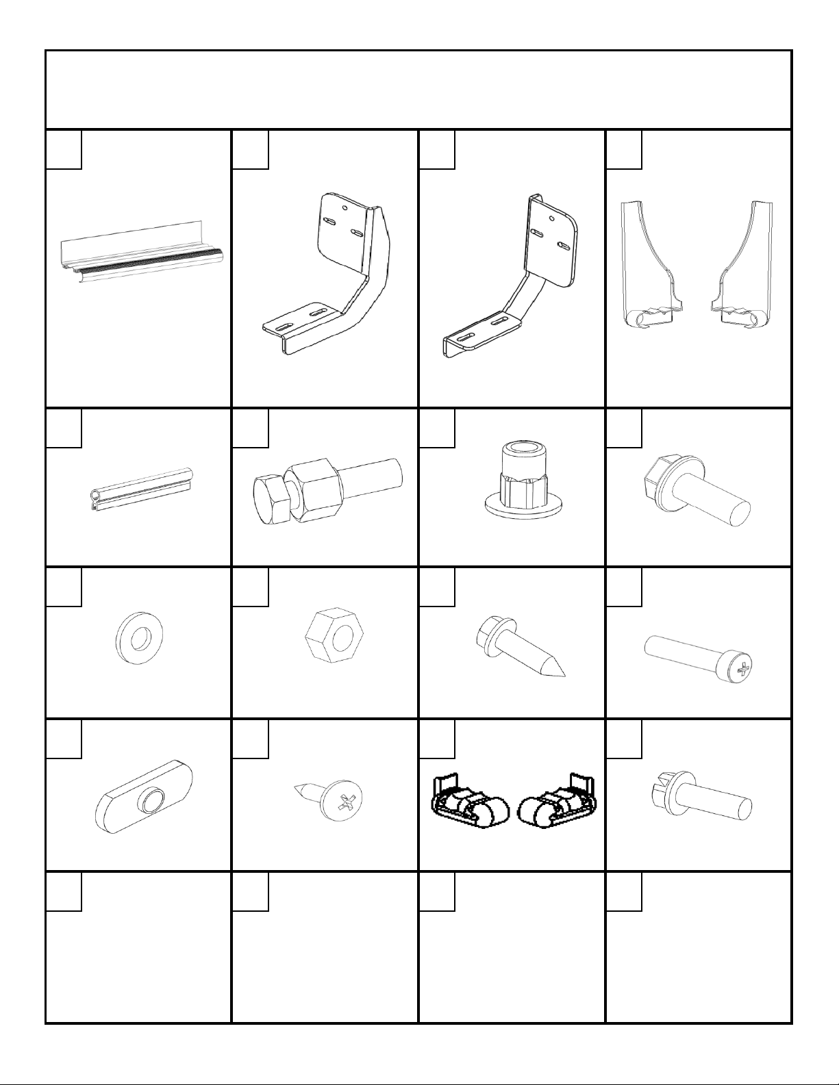
A B C D
RUNNING BOARD RH BRACKET LH BRACKET MUD FLAP
BULB GASKET NUTSERT SET TOOL 8mm HEX NUTSERT
E F G H
8mm X 25mm
FLANGE HEAD BOLT
I
1/4" FLAT WASHER 1/4" HEX NUT
M N O
8mm THREADED
PLATE
J K
#10 X 5/8" BLACK
PHILLIPS HEAD SCREW
SHEET
METAL SCREW
END CAPS
L
P
1/4 X 1" PHILLIPS
ROUND HEAD SCREW
BLACK
1/4 X 3/4"SLOTTED
HEX HEAD BOLT
FX 31927 1 OF 10 12/16/2011
Page 4
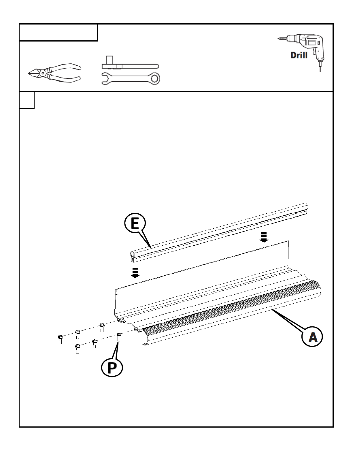
WRENCH/RATCHET
3/8", 7/16"
13mm, 15mm
TIN SNIPS
1/8"
DRILL BIT
Place the bulb-seal gasket [E] onto the backlip of the runing board [A]. Cut the bulb-seal gasket
with tin snips so that it is flush with the ends of the board
FOR REGULAR CAB:
Slide two 1/4 x 3/4" slotted hex head bolts [P] into both of the bolt channels on the bottom
side of the running board.
FOR QUAD, CREW, AND MEGA CAB:
Slide three 1/4 x 3/4" slotted hex head bolts [P] into both of the bolt channels on the bottom
side of the running board.
TOOLS REQUIRED
1
FX 31927 2 OF 10 12/16/2011
Page 5

Place the end cap [O] onto the running board as shown below. The image shown is the drivers side
side box board. Secure the end cap in place using a phillips head screwdriver and
two 1/4 x 1" black phillips head round head screws [L].
2
Place the mud flap [D] onto the running board as shown below. The image shown is the drivers side
side box board. Secure the mud flap in place using a 3/8" socket or wrench and
one black sheet metal screw [K]. Holding the end cap against the running board to minimize the
gap on the top surface, drill a 1/8" hole through the end cap and board on the bottom side .
Attached the end cap with a sheet metal screw [N].
3
FX 31927 3 OF 10 12/16/2011
Page 6

Locate the hexagon shaped holes on the inside of the rocker panel. There will be two holes
at each mounting location. The passenger side is shown below.
Insert an 8mm nutsert [G] at each location. The front of the vehicle is to the left of the picture.
4
The regular cab will not have
a middle mounting location.
FX 31927 4 OF 10 12/16/2011
Page 7

Use the nutsert set tool [F] to crimp the nutserts in the holes.
Hold the nut on the set tool with a 15mm wrench. Tighten the bolt in the set tool with a 13mm
Torque the nutserts to the spcification below to insure they are set correctly.
5
Put a 8mm x 25mm bolt [H] through the top hole in the brace [B] and thread into the
8mm threaded plate [M] until the bolt starts to come through the threaded plate.
Repeat this for the other braces.
6
socket.
FX 31927 5 OF 10 12/16/2011
Page 8

When the brace is put up to the vehicle mounting location, the threaded plate
must go into the large slot above the nutserts previously installed.
7
Thread 2 of the 8mm x 25mm bolts [H] through the slots in the braces into the nutserts.
Only engage the bolts a few threads into the nutserts.
Do NOT tighten at this time.
Repeat this step at the other two brace mounting locations.
FX 31927 6 OF 10 12/16/2011
Page 9

Remove and discard the small cladding located in front of the front door.
8
Align the bolt in the channels on the bottom of the running with the slots in the braces and
insert the bolts into the slots. Attach the running board to the braces using the 1/4" flat washers [I],
and the 1/4" hex nuts [J].
The flap should be located against the wheel well.
This step continued on the next page.
9
FX 31927 7 OF 10 12/16/2011
Page 10

Place the running board on the braces with the bulb seal up against the rocker panel.
The back lip of the board must sit on the outside of the rocker panel.
Push up on the brace to put tension on the threaded plate in the large slot. Tighten the bolt
with the threaded plate using a 13mm socket. Air tools are recommended for this.
After the bolt with the threaded plate is tightened, tighten the remaining two 8mm bolts.
10
FX 31927 8 OF 10 12/16/2011
Page 11

Align the board with the vehicle and make sure that the mud flap is up against the wheel well.
Once the board location is set, use a 7/16" socket/wrench to tighten the nuts attaching the
board to the brace.
11
Align the flap with the wheel well and
drill three 1/8" holes through the mudflap
and the sheet metal of the inner fender well.
On the bottom of the board drill a 1/8"
hole through the end cap into the board.
12
FX 31927 9 OF 10 12/16/2011
Page 12

Attach the mudflap using four #10 screws [N].
13
Check to insure that all hardware has been tightened.
Repeat process for other side of vehicle.
FX 31927 10 OF 10 12/16/2011
 Loading...