

Dee Zee DZ 951550, DZ 951600, DZ 951800 Installation Instructions Manual
INVIS-A-RACK INSTALLATION INSTRUCTION
DZ 951550, DZ 951600, DZ 951800
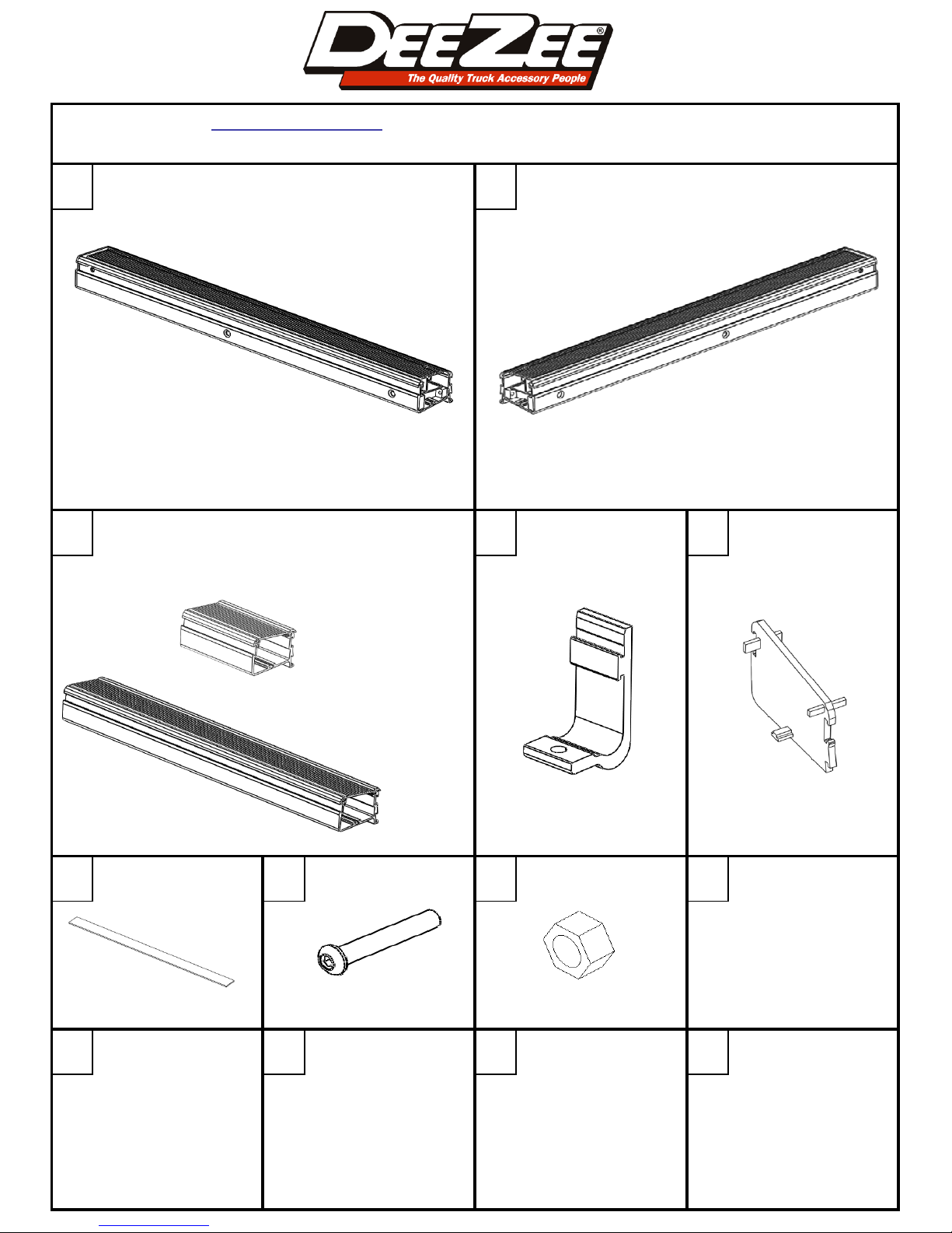
A B
DRIVER FRONT / PASSENGER REAR PASSENGER FRONT / DRIVER REAR
IR-HOUSING-ASSEML X2 IR-HOUSING-ASSEMR X2
BUNGEE BOX
MOUNTING HOOK SECTION CAP
EDC
THERE IS NO BUNGEE BOX IN THE 5 FT. APPLICATION
6 FT.
8 FT.
VARIES X2 DZE-539-150CP X8 ECIR4 X4
FOAM GASKET 3/8" BOLT 3/8" NUT
F G H
FGT 32 16 FT. PN 220 X8 PN 90 X8
WRENCH
UTILITY KNIFE OR SCISSORS
9/16"
7/32" ALLEN WRENCH OR SOCKET
RATCHET
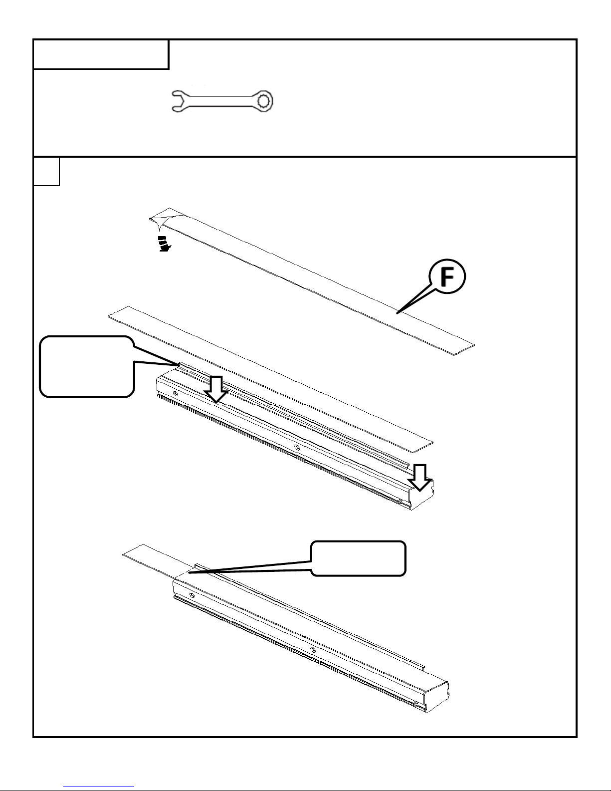
Peel a portion of the paper back from the adhesive on the foam gasket [F].
Apply the sticky side of the gasket to the bottom of the rack assemblies and bungee boxes (if applicable).
Use the lip on the bottom side as a guide to apply the gasket straight with the part.
TOOLS REQUIRED
After applying the gasket, use a utility knife to trim the gasket with the end of the part.
1
ALIGN GASKET
WITH THIS
EDGE
TRIM AT EDGE
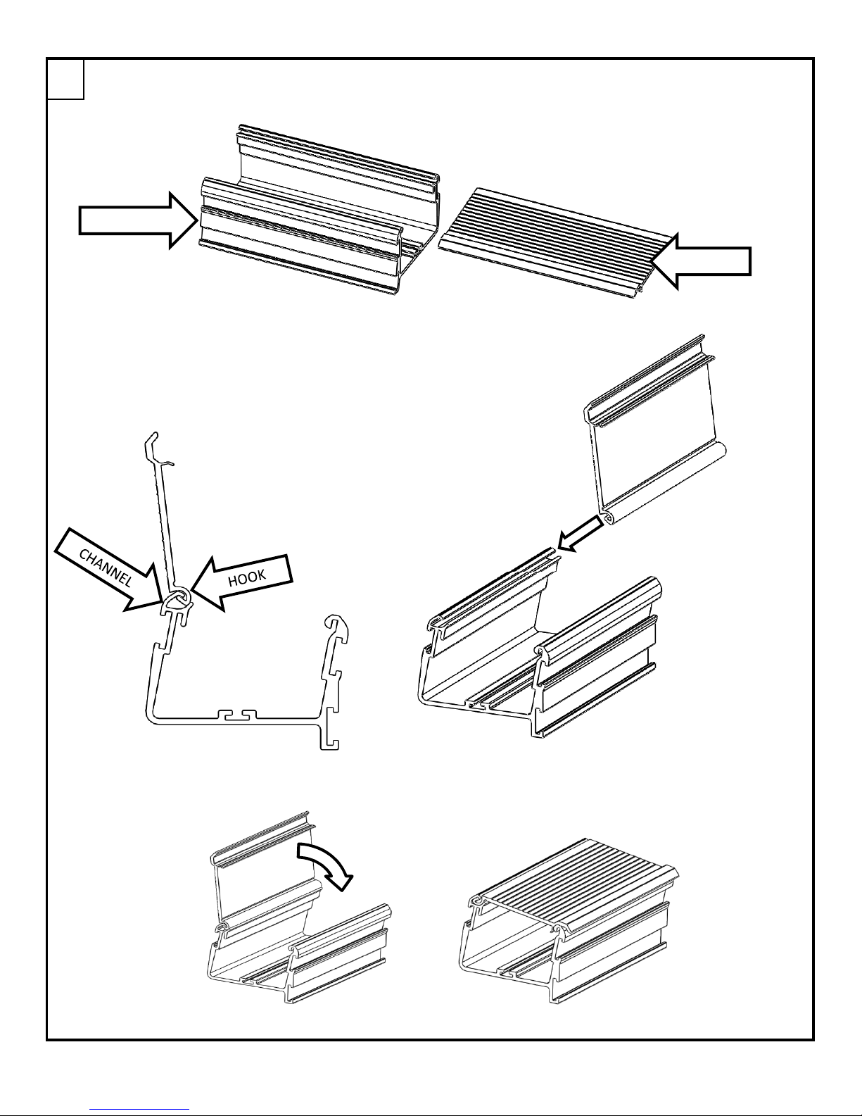
If your application includes bungee boxes, they will need to be assembled.
With the lid held almost perpendicular
to the base, align the hook on the back
of the lid with the channel on the base.
Slide the lid onto the base.
2
When the edges are flush, close the lid.
BASE
LID
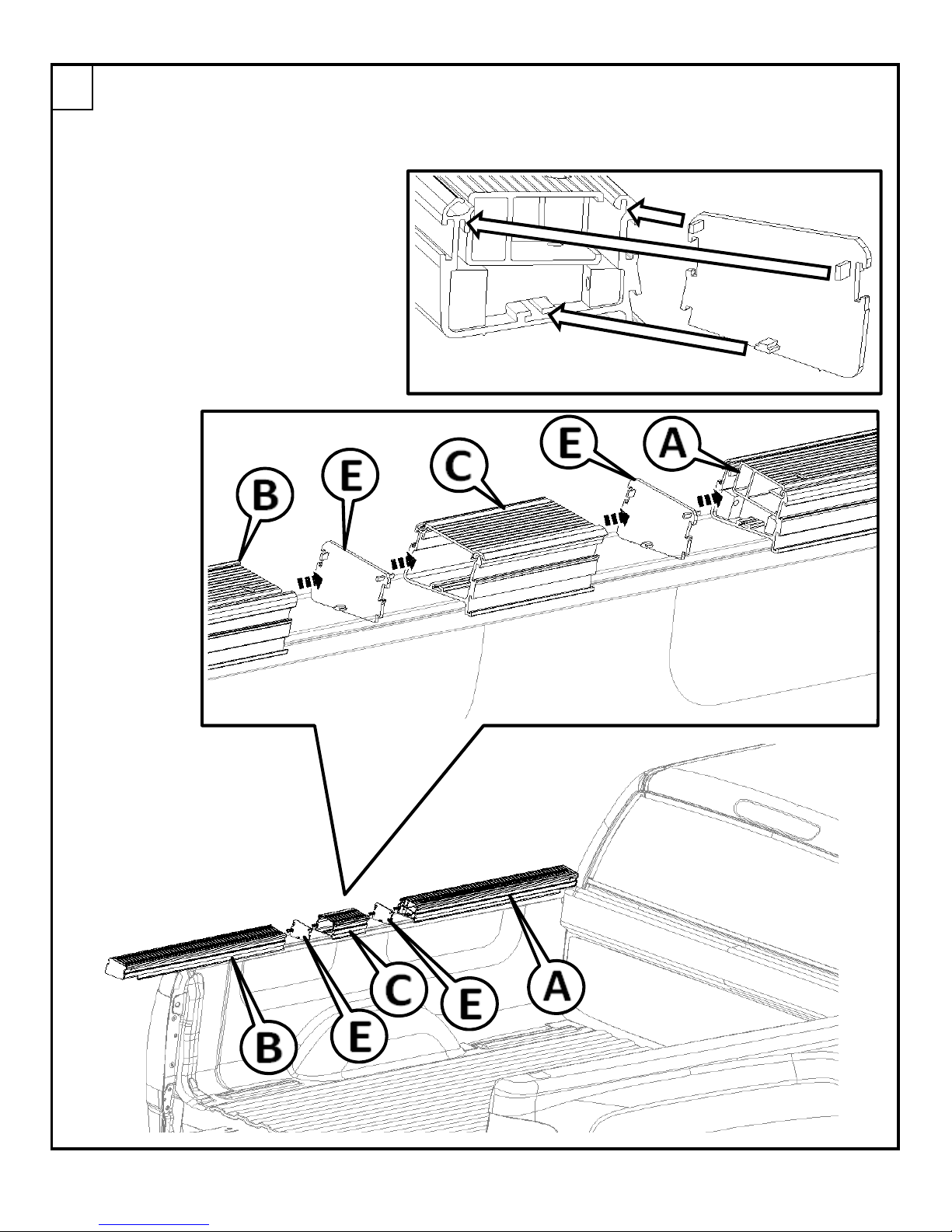
Set the first assembly [A] on the bed of the truck on the driver's side near the cab.
This step is shown with the small bungee box for the 6' bed. If you are installing on a 5.5' bed, there
will not be a bungee box, and you will only use one of the section cap [E] per side.
If you are installing on an 8' bed, the bungee box will be longer than what is shown
below, but will install in the same way.
Assemble the sections as shown below.
The tabs in the section cap [E] fit into
the extrusion as shown in this figure.
When installed to outside profile of the
section cap will match the extrusion
profile.
3
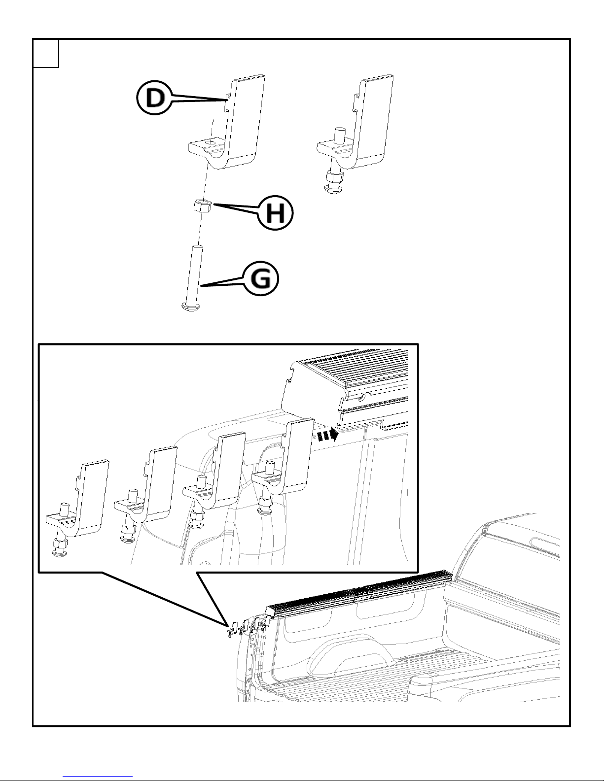
Thread one of the 3/8" nuts [H] onto the 3/8" bolt [G], then thread the bolt part way
into the hole on the hold down clamp [D]. There will be 4 of these used per side.
Slide the 4 hold down clamps into the bottom channel on the back side.
4
 Loading...