

Page 1

Before returning this product
to the store of purchase
Contact Dee Zee if you experience the following problems:
•MissingParts
•InstallationProblems/Questions
•WarrantyQuestions
1.800.779.2102
Hoursofoperation:8am-5pmCST,Mon-Friday
Reviewcompletewarrantypolicyandregisteryourproductat:
www.deezee.com
Page 2
Dee Zee Running Board Installation Instructions
Congratulations on your purchase of a quality Dee Zee product. Dee Zee is
recognized as having the highest quality running boards and accessories on
the market today. We have earned this reputation by offering our customers
a product they can be proud to place on their vehicles. Dee Zee meets all
the criteria of manufacturing a custom-fit product which guarantees it to
be the easiest product to install.
Note: Please take time to read all of the instructions before beginning this installation.
War ning! Please check for wiring or other obstr uctions before drilling any holes into
the vehicle. If it is necessar y to drill any holes into the vehicle, Dee Zee recommends
putting a sealant or rust inhibitor around all holes drilled into the body of the vehicle.
War ning! It is the sole responsibility of the vehicle owner to check for tire clearance.
War ning! It is unlawful and dangerous to ride on r unning boards or side box boards
while the vehicle is in motion.
Cleaning Instructions: To maintain the bright finish of your Dee Zee running boards,
clean with a mild deter gent. For our stainless steel products and accessories, the
application of a high grade automotive type wax is recommended.
If you should happen to have any questions with this product or you have an
installation question, please feel fr ee to call us at:
1-800-779-8222
If you would like to find out mor e infor mation on Dee Zee’s products please
feel free to visit our website at:
WWW.DEEZEE.COM
Page 3
*** BOARD SOLD SEPARATELY
X2
B 2014LP
X3
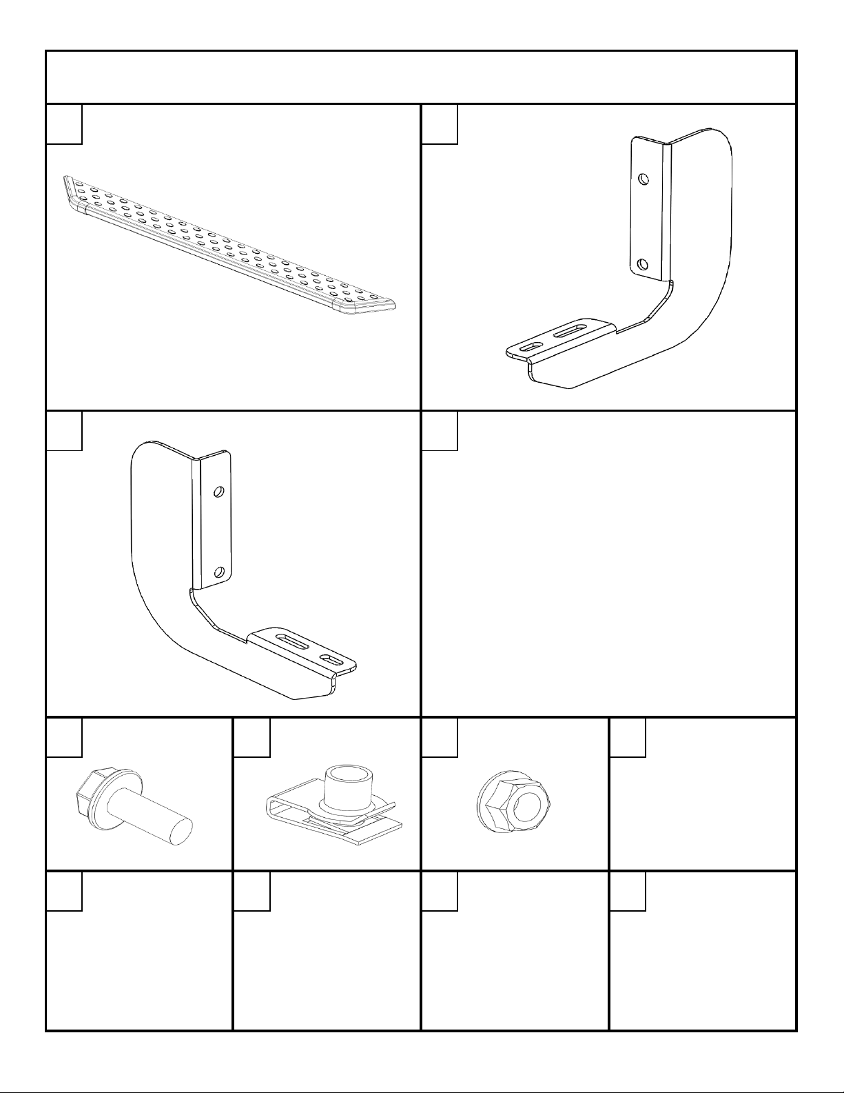
NXT RUNNING BOARD INSTALLATION INSTRUCTION
DZ 16326 FORD SUPER DUTY 1999-CURRENT
A B
B 2014RP
X3
PN 525
X12
PN 909
X12
PN 526
X12
SIDE STEP TUBE
BRACKET LEFT HAND
C
BRACKET RIGHT HAND
D E F
8mm X 25mm
FLANGE HEAD BOLT
8mm U-NUT 8mm X 20mm
FLANGE HEAD BOLT
DZ 16326 1 of 5 11/18/2011
Page 4
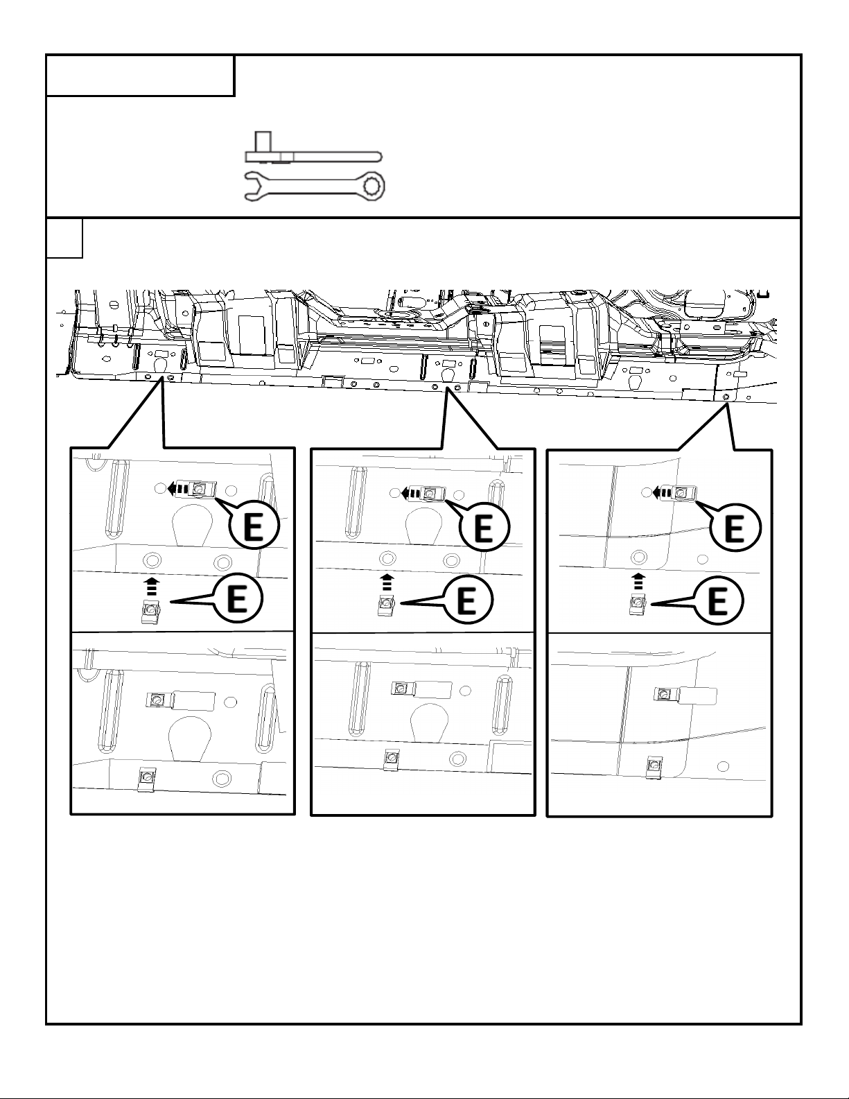
WRENCH/RATCHET
13mm
Install the 8mm u-nut [E] as shown below.
The driver's side crew cab is shown. The front of the vehicle is to the right of the picture.
TOOLS REQUIRED
The regular cab does not have a middle mounting location. Extra brackets and hardware
may be discarded.
1
DZ 16326 2 of 5 11/18/2011
Page 5

Attached the mounting brackets [B] to the mounting locations with the previously installed U-nuts
using the 8mm x 25mm bolt [D].
2
Bracket [C] will be used for the mounting locations on the passenger side.
Do not completely tighten at this time.
DZ 16326 3 of 5 11/18/2011
Page 6

Align the bolts in the channels on the underside of the running board with the slots in the
mounting braces and loosley attach the board to the brace at each location with the 8mm nuts [F].
Do not completely tighten at this time.
3
Using a 13mm socket/wrench, tighten the bolts that attach the brace to the vehicle. Once all of the braces
have been tighened, adjust the board front/back and in/out to align it with the vehicle.
4
DZ 16326 4 of 5 11/18/2011
Page 7

Once the board location has been set, tighten the nuts holding the board to the braces using
a 13mm socket/wrench.
5
Make sure all bolts are tightened. Repeat steps for other side.
DZ 16326 5 of 5 11/18/2011
Page 8

*** TUBES SOLD SEPARATELY
X2
X3
6" OVAL SIDE STEP INSTALLTION
FORD SUPER DUTY 1999-CURRENT
A B
X3
FROM TUBE
X8
FROM TUBE
X8
X12
X12
BOLT PACK
X12
BOLT PACK
X12
SIDE STEP TUBE
BRACKET LEFT HAND
C
BRACKET RIGHT HAND
D E F G
8mm X 25mm
FLANGE HEAD BOLT
8mm U-NUT
FLANGE HEAD BOLT
8mm U-NUT8mm X 20mm
1 of 5 1/4/2013
Page 9

WRENCH/RATCHET
13mm
Install the 8mm u-nut [E] as shown below.
The driver's side is crew cab is shown. The front of the vehicle is to the right of the picture.
TOOLS REQUIRED
The regular cab does not have a middle mounting location. Extra brackets and hardware
may be discarded.
1
2 of 5 1/4/2013
Page 10

Attached the mounting brackets [B] to the mounting locations with the previously installed U-nuts
using the 8mm x 25mm bolt [D].
2
Bracket [C] will be used for the mounting locations on the passenger side.
Tighten bolts with a 13mm Socket or wrench.
3 of 5 1/4/2013
Page 11

Once the brackets are in place, set the tube on the braces and adjust as necessary front to back.
Look under the tube to determine which sets of slots will be used to attach the tube to the braces.
The crew cab tube is shown.
3
Remove the tube and install the 8mm U-nuts [G] that were supplied with the tubes into the
slots identified in the previous step. Use 2 U-nuts per brace location.
4
4 of 5 1/4/2013
Page 12

Set the tube back on the brackets and slide the U-nuts in the tube slots so that they align
with the mounting slots in the braces. Repeat at all mounting locations.
Attach the tube to the braces using the 8mm x 20mm bolts [F] that were supplied
with the tube step. Tighten bolts with a 13mm wrench or socket. Repeat at all mounting locations.
5
Make sure all bolts are tightened. Repeat steps for other side.
5 of 5 1/4/2013
 Loading...