

Page 1
Before returning this product
to the store of purchase
Contact Dee Zee if you experience the following problems:
•MissingParts
•InstallationProblems/Questions
•WarrantyQuestions
1.800.779.2102
Hoursofoperation:8am-5pmCST,Mon-Friday
Reviewcompletewarrantypolicyandregisteryourproductat:
www.deezee.com
Page 2

Dee Zee Running Board Installation Instructions
Congratulations on your purchase of a quality Dee Zee product. Dee Zee is
recognized as having the highest quality running boards and accessories on
the market today. We have earned this reputation by offering our customers
a product they can be proud to place on their vehicles. Dee Zee meets all
the criteria of manufacturing a custom-fit product which guarantees it to
be the easiest product to install.
Note: Please take time to read all of the instructions before beginning this installation.
War ning! Please check for wiring or other obstr uctions before drilling any holes into
the vehicle. If it is necessar y to drill any holes into the vehicle, Dee Zee recommends
putting a sealant or rust inhibitor around all holes drilled into the body of the vehicle.
War ning! It is the sole responsibility of the vehicle owner to check for tire clearance.
War ning! It is unlawful and dangerous to ride on r unning boards or side box boards
while the vehicle is in motion.
Cleaning Instructions: To maintain the bright finish of your Dee Zee running boards,
clean with a mild deter gent. For our stainless steel products and accessories, the
application of a high grade automotive type wax is recommended.
If you should happen to have any questions with this product or you have an
installation question, please feel fr ee to call us at:
1-800-779-8222
If you would like to find out mor e infor mation on Dee Zee’s products please
feel free to visit our website at:
WWW.DEEZEE.COM
Page 3
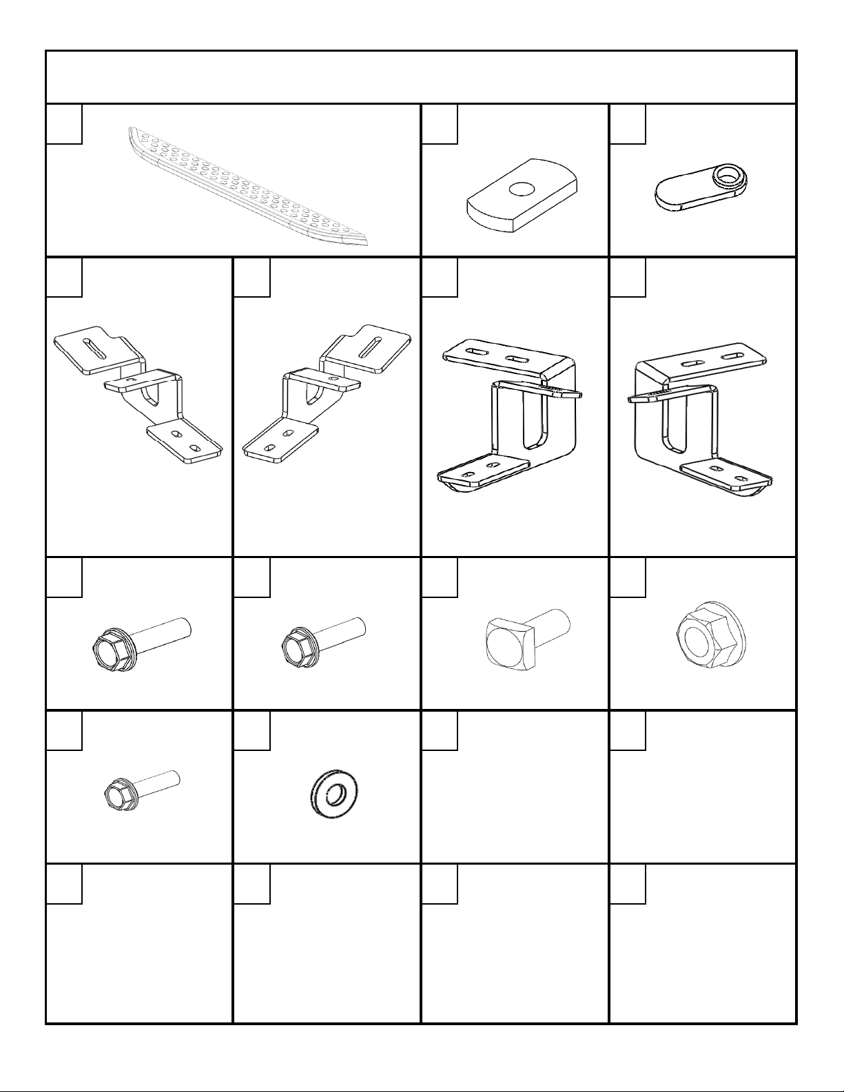
PLATE
DZ 16201
DZ 16202
DZ 16203
X2
PN 835
X6
PN 714
X6
BRACKET
BRACKET
BRACKET
BRACKET
B 1749LP
X1
B 1749RP
X1
B 1750LP
X2
B 1750RP
X2
PN 525
X6
PN 527
X6
PN 524
X12
PN 526
X12
PN 556
X1
PN 72B
X1
DZ 16260
DZ 16260DZ 16260
DZ 16260
TOYOTA HIGHLANDER
TOYOTA HIGHLANDERTOYOTA HIGHLANDER
TOYOTA HIGHLANDER
*SOLD SEPARATELY FROM THIS KIT*
LARGE THREADED SMALL THREADED
A B C
PLATE
D
H
LEFT FRONT
8mm X 25mm BOLT
E F G
RIGHT FRONT LEFT MIDDLE/REAR
I
8mm X 20mm BOLT
J
8mm SQUARE
HEAD BOLT
K
RIGHT MIDDLE/REAR
8mm NUT
L M
6mm x 20mm BOLT
DZ 16260 1 OF 13 1/30/2014
WASHER
Page 4
WRENCH/RATCHET
10mm, 13mm
TAPE
MEASURE
SCREWDRIVER
TIN SNIPS
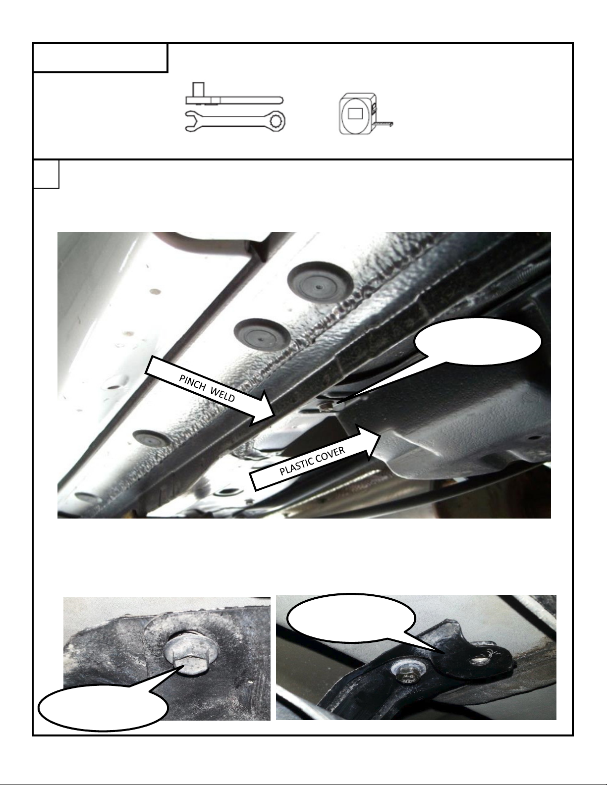
There are three brace mounting location on each side of the vehicle.
Locate the clips that attach the plastic cover to the vehicle. These will be located just inside the
pinch weld on the vehicle. There will either be 2 or 3 clips on the driver's side depending on what
model year vehicle you have. There will be 3 clips on the passenger side.
Using a 10mm socket, remove the bolt from the clip, and slide the plastic cover out of the clip.
If your vehicle only has 2 clips on the driver's side, the front mounting location for the plastic cover
will be attached with a bolt through the cover and into a metal bracket. Remove this bolt, but
do not discard it. It will be used to reattach the plastic cover.
TOOLS REQUIRED
1
BRACKET
CLIP
FRONT BOLT
DZ 16260 2 OF 13 1/30/2014
Page 5
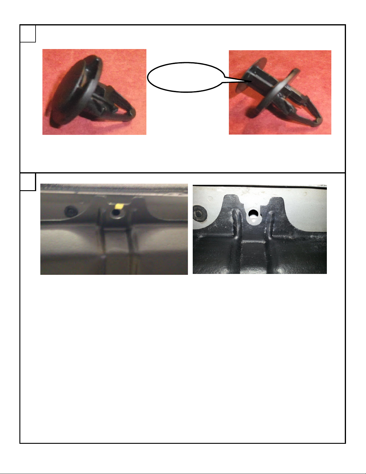
Remove the plastic clips from the vehicle. Do this by using a screwdriver to release the center
post in the clip.
Once the center post has been released, remove the clip from the vehicle and discard.
Cut the plastic cover tabs as shown for the middle and rear as shown.
If your vehicle did not have the metal bracket shown at the end of step one, you will also need
to cut the cover tab at the front mounting location.
2
3
POST
DZ 16260 3 OF 13 1/30/2014
Page 6

There are a series of rubber plugs on the outside of the pinch weld. 3 of these locations will
also be used to mount the bracing.
For the middle and rear braces:
Which plug will be used also varies by vehicle model year. The best way to determine which plugs
to remove is to hold the brace up to the mounting location where the clip was removed in Step 2
4
PLUG
DZ 16260 4 OF 13 1/30/2014
Page 7

For the front brace:
The plug directly in front of the metal bracket will be used. If your vehicle does not have a metal
bracket at this location, then it will be directly in front of the clip hole removed from Step 2.
Thread the short 8mm bolt [I] through the front slot in the brace [F] into the large threaded plate [B].
Thread the long 8mm bolt [H] through one of the back slots in the brace into the small threaded
plate [C].
If the rubber plugs match the first picture in Step 4, you will need to use the other slot
in the back of the brace.
5
INSTALL PLATE WITH
FLANGE TOWARD
DZ 16260 5 OF 13 1/30/2014
Page 8

For middle and rear braces:
Insert the small threaded plate into the hole where the plastic clip was removed in step 2.
Once the small threaded plate has been inserted, insert the large threaded plate into the hole that
the rubber plug was removed from in step 4.
6
DZ 16260 6 OF 13 1/30/2014
Page 9

Once both threaded plates have been inserted, slide the plastic cover tab in between the brace and
the vehicle to secure the cover.
Pull down on the brace to put tension on the threaded plates and tighten the bolts using a
13mm socket.
TIGHTEN
TIGHTEN
PULL DOWN
DZ 16260 7 OF 13 1/30/2014
Page 10

If the front driver's side mounting location has the metal bracket, remove the bolt that attaches it
to the vehicle using a 10mm socket. Discard the bolt.
Thread the short 8mm bolt [I] through the front slot in the brace [D] into the large threaded plate [B].
7
REMOVE BOLT
DZ 16260 8 OF 13 1/30/2014
Page 11

Insert the threaded plate into the hole from which the rubber plug was removed.
Using the 6mm bolt [L] and the washer [M], attach the brace to the vehicle through the metal
bracket that attaches the plastic cover.
Tighten the bolt using a 10mm socket.
BRACKET
DZ 16260 9 OF 13 1/30/2014
Page 12

Pull down on the brace to put tension on the threaded plate and tighten the bolt using a
13mm socket.
To reattach the cover at the driver's front location, the cover will need to be trimmed for brace
clearance.
9
TIGHTEN
PULL DOWN
TRIM BACK TO
VERTICAL WALL
DZ 16260 10 OF 13 1/30/2014
Page 13

Reattach the cover to the metal bracket with the bolt previously removed using a 10mm socket.
I
f there is no metal bracket at the front location
, the driver's side front brace [D] will attach like the
middle and rear braces. This is also how the front passenger side brace [E] attaches.
Thread the short 8mm bolt [I] through the front slot in the brace [D] into the large threaded plate [B].
Thread the long 8mm bolt [H] through the back slot in the brace into the small threaded
plate [C].
Repeat Step 6 for the front brace.
10
11
DZ 16260 11 OF 13 1/30/2014
Page 14

Slide two square head bolts [J] into the channels on the underside of the running board.
Line the bolts in the running board up with the slots in the braces.
Place the board on the braces with the bolts through the brace slots.
6
7
DZ 16260 12 OF 13 1/30/2014
Page 15

Slide the board to the desired location from front to rear. A tape measure may be used to insure
the board is centered between the wheel wells. Slide the board in/out on the brace slots to place
the board an even distance from the vehicle.
Attach the board to the braces using the flange nut [K]. Tighten all bolts with a 13mm socket.
Repeat process for passenger side.
8
DZ 16260 13 OF 13 1/30/2014
 Loading...