

Page 1
Before returning this product
to the store of purchase
Contact Dee Zee if you experience the following problems:
•MissingParts
•InstallationProblems/Questions
•WarrantyQuestions
1.800.779.2102
Hoursofoperation:8am-5pmCST,Mon-Friday
Reviewcompletewarrantypolicyandregisteryourproductat:
www.deezee.com
Page 2

Dee Zee Running Board Installation Instructions
Congratulations on your purchase of a quality Dee Zee product. Dee Zee is
recognized as having the highest quality running boards and accessories on
the market today. We have earned this reputation by offering our customers
a product they can be proud to place on their vehicles. Dee Zee meets all
the criteria of manufacturing a custom-fit product which guarantees it to
be the easiest product to install.
Note: Please take time to read all of the instructions before beginning this installation.
War ning! Please check for wiring or other obstr uctions before drilling any holes into
the vehicle. If it is necessar y to drill any holes into the vehicle, Dee Zee recommends
putting a sealant or rust inhibitor around all holes drilled into the body of the vehicle.
War ning! It is the sole responsibility of the vehicle owner to check for tire clearance.
War ning! It is unlawful and dangerous to ride on r unning boards or side box boards
while the vehicle is in motion.
Cleaning Instructions: To maintain the bright finish of your Dee Zee running boards,
clean with a mild deter gent. For our stainless steel products and accessories, the
application of a high grade automotive type wax is recommended.
If you should happen to have any questions with this product or you have an
installation question, please feel fr ee to call us at:
1-800-779-8222
If you would like to find out mor e infor mation on Dee Zee’s products please
feel free to visit our website at:
WWW.DEEZEE.COM
Page 3
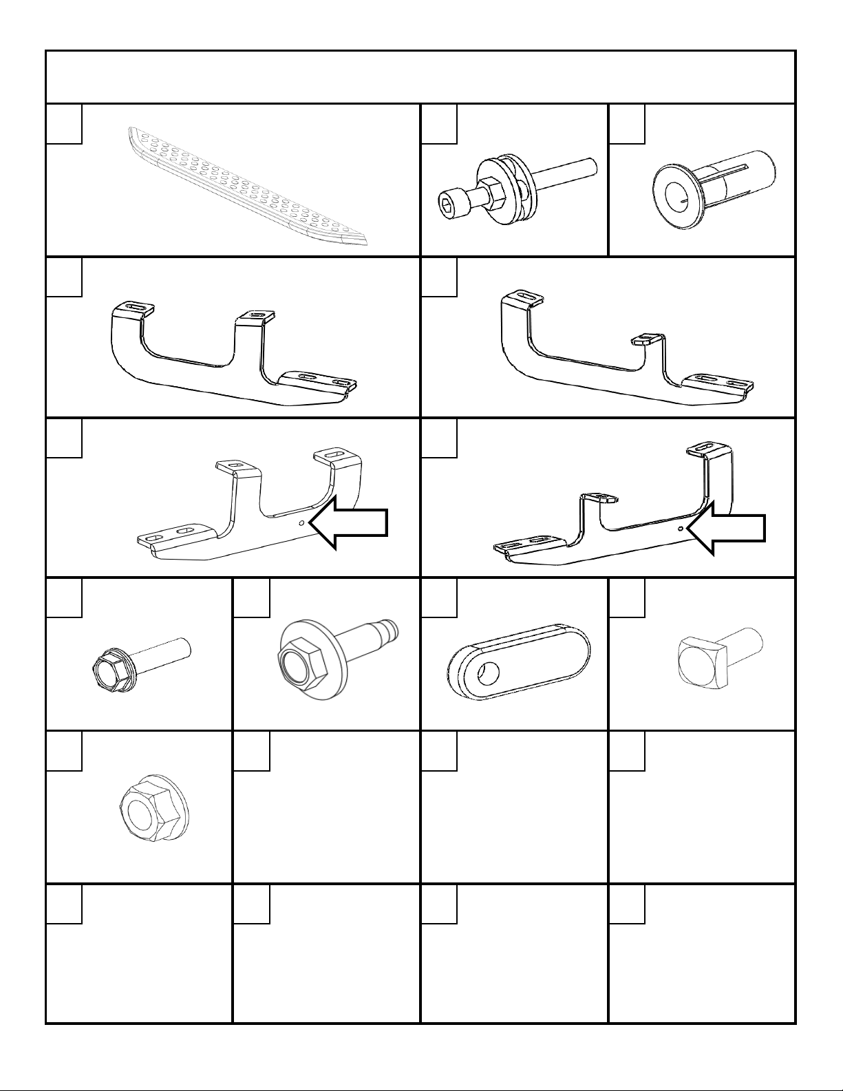
DZ 16201
DZ 16202
DZ 16203
X2
PN 685
X1
PN 1094
X4
DRIVER SIDE FRONT BRACE
DRIVER SIDE REAR BRACE
B 2179P
X1
B 2180P
X1
PASSENGER SIDE FRONT BRACE
PASSENGER SIDE FREAR BRACE
B 2181P
X1
B 2182P
X1
PN 525
X4
PN 653
X4
PN 741
X4
PN 524
X8
PN 526
X8
*SOLD SEPARATELY FROM THIS KIT*
DZ 16253
DZ 16253DZ 16253
DZ 16253
NISSAN PATHFINDER 2013-CURRENT
NISSAN PATHFINDER 2013-CURRENTNISSAN PATHFINDER 2013-CURRENT
NISSAN PATHFINDER 2013-CURRENT
NUTSERT SET TOOL 8mm NUTSERT
A B C
D
F G
HOLE
H
8mm X 25mm BOLT 6mm THREADED
I
6mm BOLT
E
J
PLATE
K
HOLE
8mm SQUARE
HEAD BOLT
L
8mm NUT
DZ 16253 1 OF 9 7/31/2013
Page 4
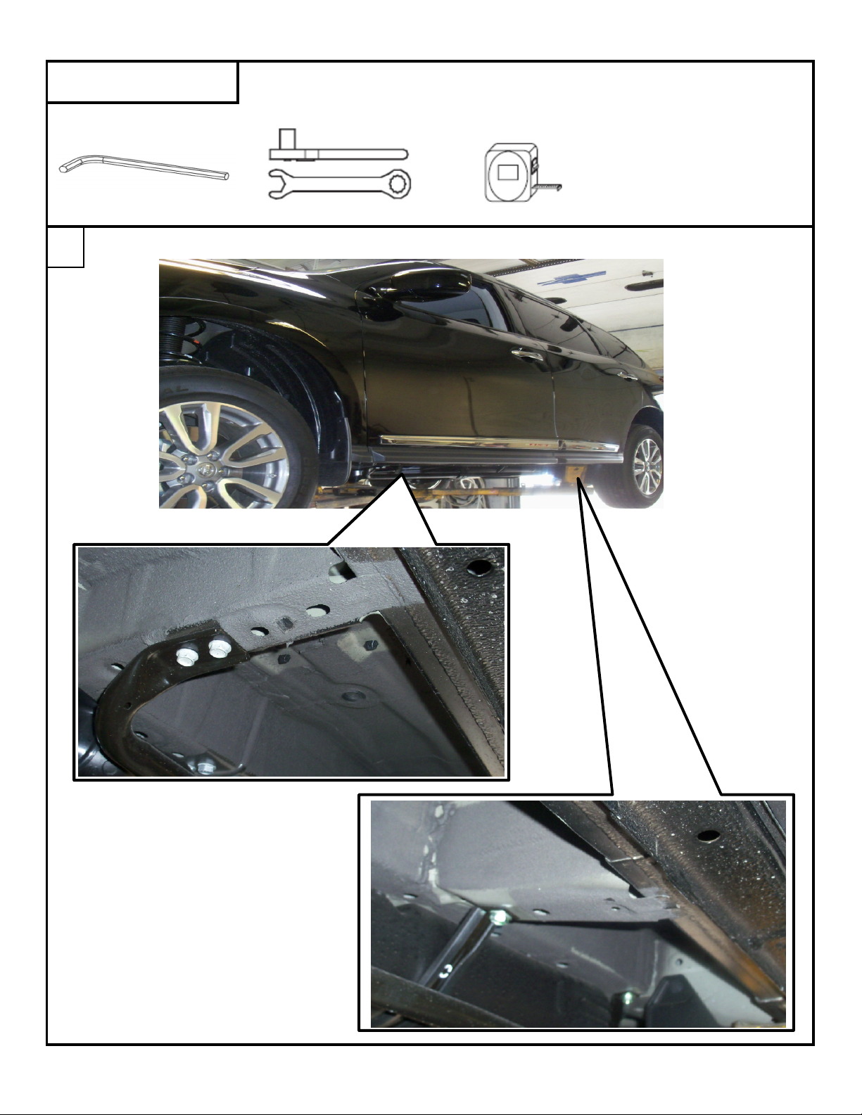
WRENCH/RATCHET
10mm, 13mm
TAPE
MEASURE
M6 ALLEN
Locate the mounting locations as shown below. The driver's side is shown.
TOOLS REQUIRED
1
DZ 16253 2 OF 9 7/31/2013
Page 5

There are 7 rubber plugs along the edge of the rocker panel.
Starting from the front tire, remove the 2nd and 5th rubber plug.
Thread a nutsert [C] on to the nutsert tool [B], and insert the nutsert into the hole shown below.
FRONT MOUNTING LOCATION
The nutsert will not stay in the hole
by itself until it has been
compressed. This image
illustrates how and where
the nutsert goes.
2
3
DZ 16253 3 OF 9 7/31/2013
Page 6

Using a 13 wrench and a 6mm allen socket, tighten
the nutsert into place. This is done by holding the
6mm allen wrench/socket stationary and turning the
with the 13mm wrench clockwise. It will take between
nine and twelve 360 degree turns to tightenthe nutsert.
Be careful not to overtighten the nutsert as this will
strip the threads.
Using the 6mm bolt [I] and threaded plate [J], thread the bolt into the plate in the front mounting
hole in the driver side front brace [D].
Only thread the bolt into the plate 3-4 turns.
4
13mm WRENCH
6mm ALLEN
5
DZ 16253 4 OF 9 7/31/2013
Page 7

Put the threaded plate into the hole where the 2nd rubber plug was removed.
Once the threaded plate is in the hole, attach the rear mounting hole in the brace with
an 8mm bolt [H] into the nutsert installed in a previous step.
Thread the 8mm bolt in until it is hand tight.
Pull down on the front part of the brace to put tension on the threaded plate that is in the
rocker panel hole. Tighten the 6mm bolt using a 10mm socket.
Torque the 8mm bolt to 10 ft-lbs. Torque the 6mm bolt to 8 ft-lbs.
6
TIGHTEN BOLT
HERE
PULL
BRACE
DOWN
DZ 16253 5 OF 9 7/31/2013
Page 8

Thread a nutsert [C] on to the nutsert tool [B], and insert the nutsert into the hole shown below.
Repeat the process fron Step 4 to install and torque the nutsert.
Using the 6mm bolt [I] and threaded plate [J], thread the bolt into the plate in the front mounting
hole in the driver side rear brace [E].
Only thread the bolt into the plate 3-4 turns.
7
8
DZ 16253 6 OF 9 7/31/2013
Page 9

Put the threaded plate into the hole where the 5th rubber plug was removed.
Once the threaded plate is in the hole, attach the rear mounting hole in the brace with
an 8mm bolt [H] into the nutsert installed in a previous step.
Thread the 8mm bolt in until it is hand tight.
Pull down on the front part of the brace to put tension on the threaded plate that is in the
rocker panel hole. Tighten the 6mm bolt using a 10mm socket.
Torque the 8mm bolt to 10 ft-lbs. Torque the 6mm bolt to 8 ft-lbs.
9
THREADED PLATE HERE
TIGHTEN BOLT
HERE
PULL
BRACE
DOWN
DZ 16253 7 OF 9 7/31/2013
Page 10

Slide two square head bolts [K] into the channels on the underside of the running board.
Line the bolts in the running board up with the slots in the braces.
Place the board on the braces with the bolts through the brace slots.
10
11
DZ 16253 8 OF 9 7/31/2013
Page 11

Slide the board to the desired location from front to rear. A tape measure may be used to insure
the board is centered between the wheel wells. Slide to board in/out on the brace slots to place
the board an even distance from the vehicle.
Attach the board to the braces using the flange nut [K]. Tighten all bolts with a 13mm socket.
Repeat process for passenger side.
12
DZ 16253 9 OF 9 7/31/2013
 Loading...