

Page 1
Before returning this product
to the store of purchase
Contact Dee Zee if you experience the following problems:
•MissingParts
•InstallationProblems/Questions
•WarrantyQuestions
1.800.779.2102
Hoursofoperation:8am-5pmCST,Mon-Friday
Reviewcompletewarrantypolicyandregisteryourproductat:
www.deezee.com
Page 2

Dee Zee Running Board Installation Instructions
Congratulations on your purchase of a quality Dee Zee product. Dee Zee is
recognized as having the highest quality running boards and accessories on
the market today. We have earned this reputation by offering our customers
a product they can be proud to place on their vehicles. Dee Zee meets all
the criteria of manufacturing a custom-fit product which guarantees it to
be the easiest product to install.
Note: Please take time to read all of the instructions before beginning this installation.
War ning! Please check for wiring or other obstr uctions before drilling any holes into
the vehicle. If it is necessar y to drill any holes into the vehicle, Dee Zee recommends
putting a sealant or rust inhibitor around all holes drilled into the body of the vehicle.
War ning! It is the sole responsibility of the vehicle owner to check for tire clearance.
War ning! It is unlawful and dangerous to ride on r unning boards or side box boards
while the vehicle is in motion.
Cleaning Instructions: To maintain the bright finish of your Dee Zee running boards,
clean with a mild deter gent. For our stainless steel products and accessories, the
application of a high grade automotive type wax is recommended.
If you should happen to have any questions with this product or you have an
installation question, please feel fr ee to call us at:
1-800-779-8222
If you would like to find out mor e infor mation on Dee Zee’s products please
feel free to visit our website at:
WWW.DEEZEE.COM
Page 3
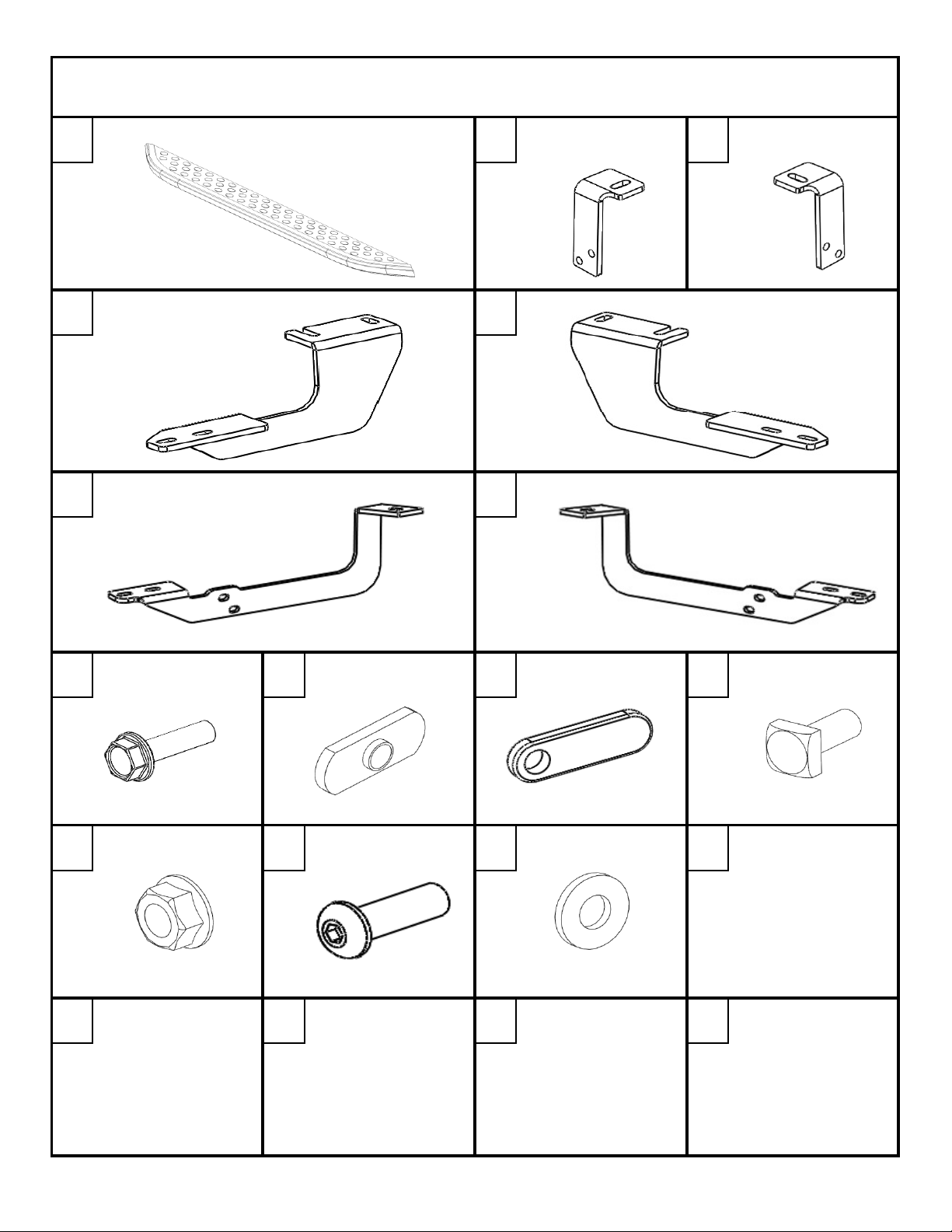
BRACKET
BRACKET
DZ 16201
DZ 16202
DZ 16203
X2
B 2189LP
X1
B 2189RP
X1
DRIVER SIDE FRONT BRACE
PASSENGER SIDE REAR BRACE
B 2190LP
X1
B 2190RP
X1
DRIVER SIDE REAR BRACE
PASSENGER SIDE REAR BRACE
B 2188LP
X1
B 2188RP
X1
PN 525
X8
PN 835
X4
PN 742
X4
PN 524
X8
PN 526
X12
PN 174
X 4
PN 113B
X4
DZ 16223
DZ 16223DZ 16223
DZ 16223
FORD ESCAPE
FORD ESCAPEFORD ESCAPE
FORD ESCAPE
*SOLD SEPARATELY FROM THIS KIT*
LEFT SUPPORT RIGHT SUPPORT
A B C
D
F
H
8mm X 25mm BOLT
E
G
I
8mm THREADED OFFSET THREADED
PLATE HEAD BOLT
J
PLATE
K
8mm SQUARE
L M
8mm NUT
DZ 16223 1 OF 15 8/9/2013
3/8 " BUTTON
HEAD BOLT
3/8" FLAT WASHER
ON
Page 4
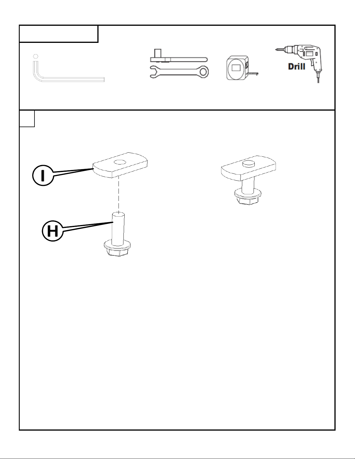
WRENCH/RATCHET
10mm, 13mm
TAPE
1/4" DRILL BIT
7/32" ALLEN
TIN SNIPS
MEASURE
Using the 8mm bolt [H] and threaded plate [I], thread the bolt into the plate.
TOOLS REQUIRED
1
DZ 16223 2 OF 15 8/9/2013
Page 5
Insert the threaded plate into the outer slot at the front mounting location.
2
DZ 16223 3 OF 15 8/9/2013
Page 6
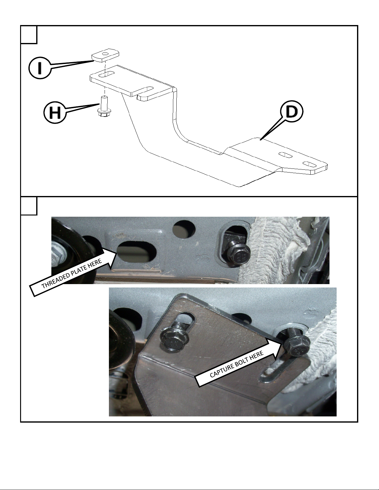
Using the 8mm bolt [H] and threaded plate [I], thread the bolt into the plate
through the slot shown below in the front driver side brace [D].
Once the bolt is threaded into the threaded plate, insert the threaded plate into the other slot in the
front mounting location. Rotate the brace to capture the bolt from Step 2 in the open ended slot.
3
4
DZ 16223 4 OF 15 8/9/2013
Page 7

Align the brace so that it is perpendicular to the vehicle. Pull down on the brace to put tension on
the threaded plates and tighten with a 13mm socket.
The rear mounting location is covered with a plastic panel.
Just in front of this panel is a cut out in the cladding.
5
TIGHTEN BOLT
HERE WITH
13mm
TIGHTEN BOLT
HERE WITH
13mm
PULL
BRACE
DOWN
6
CUT OUT
PLASTIC PANEL
DZ 16223 5 OF 15 8/9/2013
Page 8

To attach the rear mounting bracket, you will need to drill a 1/4" hole through the plastic cladding.
The 1/4" hole will be located 11/16" over from the cut-out.
It will be 1- 1/4" up from the edge of
the cladding.
ONLY DRILL THROUGH THE
PLASTIC CLADDING.
7
DZ 16223 6 OF 15 8/9/2013
Page 9

Once the hole has been drilled, release the 2 clips on either side of the cladding cut out.
Using a 10mm socket, remove the panel. One of the bolts is under the cladding.
NOTE:
SAVE THE BOLTS.
THEY WILL BE USED
TO REINSTALL
THE PANEL.
Using the 3/8" button head bolt [M],
3/8" washer [N], and offset threaded plate [J],
thread the bolt into the plate
through the slot in the mounting bracket [B].
8
9
RELEASE CLIP
10
REMOVE PANEL
DZ 16223 7 OF 15 8/9/2013
Page 10

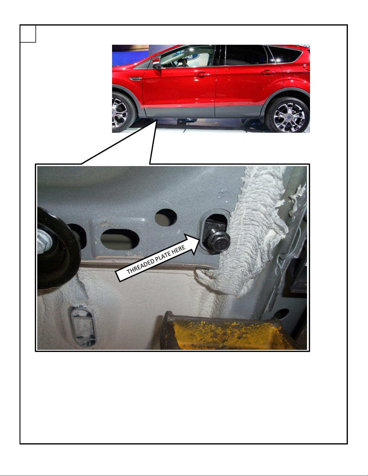
The threaded plate on mounting bracket [B] will be attaching to the hole shown below.
Pull down on the plastic cladding and insert the end of the threaded plate into the hole.
Maneuver the plate until it is completely in the opening.
11
12
THREADED PLATE HERE
DZ 16223 8 OF 15 8/9/2013
Page 11

Insert the 7/32" Allen through the hole drilled in Step 7 and into the head of the button head bolt.
Pull down on the mounting bracket to put the threaded plate under tension and tighten the bolt.
13
TIGHTEN BOLT
HERE WITH 7/32"
ALLEN
KEEP THE
BRACKET CLOSE
TO THE PINCH
WELD.
PULL
BRACE
DOWN
DZ 16223 9 OF 15 8/9/2013
Page 12

Using the 3/8" button head bolt [M],
3/8" washer [N], and offset threaded plate [J],
thread the bolt into the plate
through the slot in the rear brace [F].
Once installed on the rear brace, insert the threaded plate into the hole shown below.
14
15
THREADED PLATE HERE
DZ 16223 10 OF 15 8/9/2013
Page 13

Using the 8mm bolt [H] and 8mm nut [L], attach the rear brace to the mounting bracket.
Do NOT completely tighten at this time.
Move the brace and the threaded plate so that the threaded plate is contacting the hole on both sides.
Pull down on the brace to put tension on the threaded plate and tighten with a 7/32" Allen.
16
17
TIGHTEN BOLT
HERE WITH 7/32"
PULL
BRACE
DOWN
DZ 16223 11 OF 15 8/9/2013
Page 14

Once the rear inner bolt is tightened, tighten the bolts connecting the rear brace to the
mounting bracket using a 13mm socket/wrench.
The plastic panel that was removed in Step 9 must be modified to make room for the brace
before it can be reinstalled. Use tin snips or aviation snips to cut a notch.
Measure form the edge as shown below. The start of the cut out will be at 6 -3/4".
The notch needs to be 1/2" to 3/4" wide and extend to the second rib in the panel.
18
TIGHTEN BOLTS
HERE WITH
19
DZ 16223 12 OF 15 8/9/2013
Page 15

Once the panel has been trimmed, reinstall it using the 10mm sockets and the bolts that
were removed earlier.
Reinstall the clips that attach the cladding to the vehicle.
20
INSERT THE TOP
PORTION OF THE
CLIP INTO THE
SHEET METAL
FIRST
AFTER THE TOP IS
INSTALLED, PUSH
IN THE BOTTOM
PART OF THE CLIP
DZ 16223 13 OF 15 8/9/2013
Page 16

Slide two square head bolts [K] into the channels on the underside of the running board.
Line the bolts in the running board up with the slots in the braces.
Place the board on the braces with the bolts through the brace slots.
21
22
DZ 16223 14 OF 15 8/9/2013
Page 17

Slide the board to the desired location from front to rear. A tape measure may be used to insure
the board is centered between the wheel wells. Slide the board in/out on the brace slots to place
the board an even distance from the vehicle.
Attach the board to the braces using the flange nut [L]. Tighten all board bolts with a 13mm socket.
Check to make sure all bolts are tightened.
Repeat process for passenger side.
15
DZ 16223 15 OF 15 8/9/2013
 Loading...