

Page 1
Before returning this product
to the store of purchase
Contact Dee Zee if you experience the following problems:
•MissingParts
•InstallationProblems/Questions
•WarrantyQuestions
1.800.779.2102
Hoursofoperation:8am-5pmCST,Mon-Friday
Reviewcompletewarrantypolicyandregisteryourproductat:
www.deezee.com
Page 2
Dee Zee Running Board Installation Instructions
Congratulations on your purchase of a quality Dee Zee product. Dee Zee is
recognized as having the highest quality running boards and accessories on
the market today. We have earned this reputation by offering our customers
a product they can be proud to place on their vehicles. Dee Zee meets all
the criteria of manufacturing a custom-fit product which guarantees it to
be the easiest product to install.
Note: Please take time to read all of the instructions before beginning this installation.
War ning! Please check for wiring or other obstr uctions before drilling any holes into
the vehicle. If it is necessar y to drill any holes into the vehicle, Dee Zee recommends
putting a sealant or rust inhibitor around all holes drilled into the body of the vehicle.
War ning! It is the sole responsibility of the vehicle owner to check for tire clearance.
War ning! It is unlawful and dangerous to ride on r unning boards or side box boards
while the vehicle is in motion.
Cleaning Instructions: To maintain the bright finish of your Dee Zee running boards,
clean with a mild deter gent. For our stainless steel products and accessories, the
application of a high grade automotive type wax is recommended.
If you should happen to have any questions with this product or you have an
installation question, please feel fr ee to call us at:
1-800-779-8222
If you would like to find out mor e infor mation on Dee Zee’s products please
feel free to visit our website at:
WWW.DEEZEE.COM
Page 3
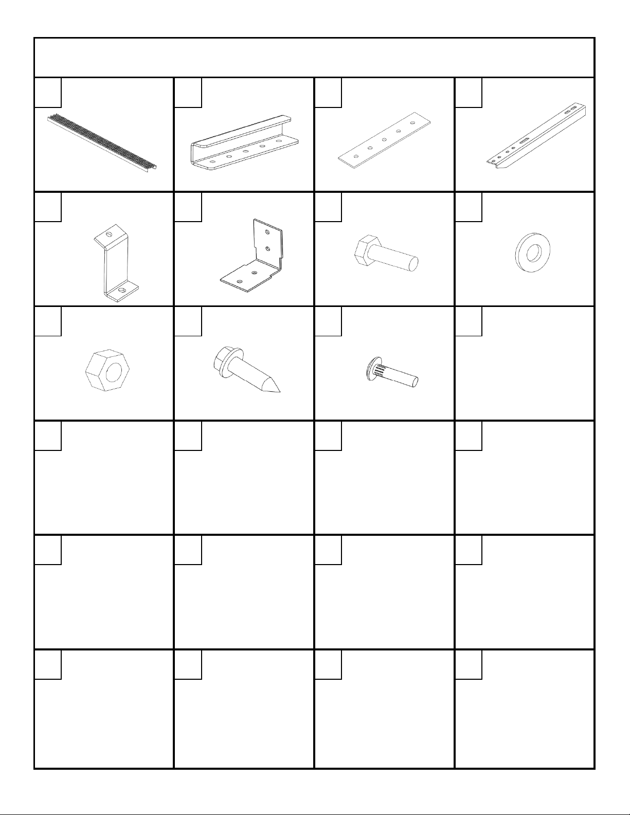
K2014P
X2
EC RSP
X4
B 1791P
X4
B 1984P
X6
BRACKET
B 1985P
X6
B 134
X6
PN 70B
X38
PN 72B
X 82
Dee Zee Rough Step Board Installation Instruction
DZ 1532 Chevy 135" & 155" WB Van
A B C D
PN 71B
X44
PN 97
X12
PN 87
X6
BOARD END CAP STRAP BRACKET ANGLE BRACE
E F
ROCKER PANEL
1/4" HEX NUT SHEET
I
FRAME BRACKET 1/4 X 3/4" HEX
G H
J K
METAL SCREW
1/4" FLAT WASHER
HEAD BOLT
1/4 X 1" RIBNECK
CARRIAGE BOLT
DZ 1532 1 OF 8 7/28/2011
Page 4

WRENCH/RATCHET
3/8", 7/16"
TAPE
MEASURE
3/16" DRILL BIT
1/4" DRILL BIT
Pre-assemble the end cap [B] and strap bracket [C] using two hex head bolts [G], four washers [H],
and two nuts [I]. Leave the parts somewhat loose for the next step.
TOOLS REQUIRED
Slide the pre-assembled end cap into the end of the board until the end cap is flush with the
end of the board. The end cap must be inside the board and the strap bracket outside the board.
Tighten the bolts with a 7/16" wrench and socket.
Repeat for the other end of the board.
1
2
DZ 1532 2 OF 8 7/28/2011
Page 5

Measure back from the front wheel well and mark the lower rocker panel at 22", 47" and 76".
This will be the approximate location for the rocker panel bracket [E].
3
Make sure there is nothing on the frame at these three location that would obstruct the frame bracket
from being installed in the later steps. If there is an obstruction, move the rocker panel bracket to
the front/rear as needed.
Hold the rocker panel bracket on the outside of the rocker panel to determine where to drill.
Make sure the vertical part of the rocker panel bracket is inside of the edge of the rocker panel
before drilling. Mark the hole, remove the bracket and drill a 1/4" hole.
Repeat this for each bracket location.
4
DZ 1532 3 OF 8 7/28/2011
Page 6

Attach the rocker brackets [E] to the rocker panel with a ribneck carriage bolt [K],
washer [H], and nut [I].
The top portion of the bracket should be inside the rocker panel.
5
Once the rocker panel brackets are installed, attach the angle braces to the bottom of the brackets
through the long slot in the angle brace using a hex head bolt [G], two washers [H], and a nut [I].
Do not completely tighten at this time.
6
DZ 1532 4 OF 8 7/28/2011
Page 7

Attach the frame bracket [F] to the angle brace using two hex head bolt [G], four washer [H],
and two nuts [I].
Do not completely tighten at this time.
Use a level to set the angle brace parallel to the ground. Clamp the frame bracket [F] to the frame.
7
Repeat this step for each bracket location.
8
DZ 1532 5 OF 8 7/28/2011
Page 8

Place the running board on the angle braces. Adjust the angle braces as needed to insure that
holes can be drilled through the bottom of the board to attach it to the braces.
ADJUST BRACE AS NEEDED
9
Do not remove the clamps holding the frame bracket [F] to the frame.
Once the angle braces are in the correct location, tighten the angle brace to the rocker panel brackets
and the frame brackets using a 7/16" socket and wrench.
Then drill 3/16" holes in the frame through the holes in the frame bracket
Repeat this step for each bracket location.
10
DZ 1532 6 OF 8 7/28/2011
Page 9

Attach the frame bracket to the frame using two sheet metal screws [J] using a 3/8" socket.
Remove the clamps holding the frame bracket [F] to the frame.
Repeat this step for each bracket location.
Use a tape measure to center the board between the wheel wells for the 135" wheel base van.
11
For the 155" wheel base van, set the board location 3" from the front wheel well.
Once the board is in the proper location, clamp the running board to the angle braces.
12
DZ 1532 7 OF 8 7/28/2011
Page 10

Drill 1/4" holes up through the slots into the board at the locations shown below.
13
Attach the running board to the angle brace using the hex head bolt [G],
1/4" flat washer [H], and 1/4" hex nut [I]. Tighten using a 7/16" wrench and socket.
Check all hardware to make sure it has been tightened.
Repeat the assembly steps for the other side of the vehicle.
14
DZ 1532 8 OF 8 7/28/2011
 Loading...