

Page 1

Before returning this product
DZ 1030
to the store of purchase
Contact Dee Zee if you experience the following problems:
•MissingParts
•InstallationProblems/Questions
•WarrantyQuestions
1.800.779.2102
Hoursofoperation:8am-5pmCST,Mon-Friday
Reviewcompletewarrantypolicyandregisteryourproductat:
www.deezee.com
Page 2

Dee Zee Running Board Installation Instructions
Congratulations on your purchase of a quality Dee Zee product. Dee Zee is
recognized as having the highest quality running boards and accessories on
the market today. We have earned this reputation by offering our customers
a product they can be proud to place on their vehicles. Dee Zee meets all
the criteria of manufacturing a custom-fit product which guarantees it to
be the easiest product to install.
Note: Please take time to read all of the instructions before beginning this installation.
Warning! Please check for wiring or other obstructions before drilling any holes into
the vehicle. If it is necessary to drill any holes into the vehicle, Dee Zee recommends
putting a sealant or rust inhibitor around all holes drilled into the body of the vehicle.
Warning! It is the sole responsibility of the vehicle owner to check for tire clearance.
Warning! It is unlawful and dangerous to ride on running boards or side box boards
while the vehicle is in motion.
Cleaning Instructions: To maintain the bright finish of your Dee Zee running boards,
clean with a mild detergent. For our stainless steel products and accessories, the
application of a high grade automotive type wax is recommended.
If you should happen to have any questions with this product or you have an
installation question, please feel free to call us at:
1-800-779-8222
If you would like to find out more information on Dee Zee’s products please
feel free to visit our website at:
WWW.DEEZEE.COM
DZ 1030.PDF 06/02/99
Page 3
DEE ZEE Running Boards
DZ 1030
96-99 Chevy / GMC Full Size 135" WB Van
A
M
X12
B ED
X2 X4
N P
Tools Required:
Outils Necessaires:
C
X2 X6
1/4“ x 1”1/4“ x 1”
X12
1/4“ x 3/4”
7/16“
3/8“
X42
S T
X54 X54
3/16“
1/4“
X6
1/4“1/4“
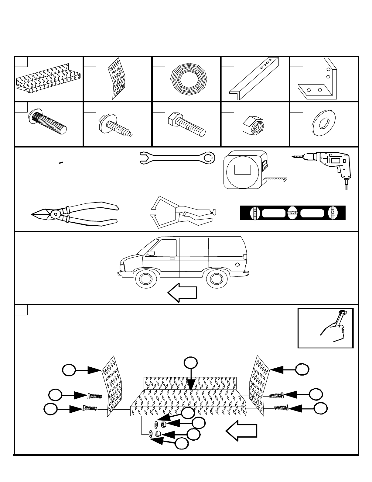
1
Place a britetread mudflap (B) onto each end of britetread running
board (A). Attach the britetread mudflap (B) to the britetread
running board (A) using 1/4 x 3/4“ hex head bolt (P), 1/4” flat
washer (T), and 1/4“ hex nut (S).
7/16“
A
B
P
P
P
B
P
T
S
S
T
DZ1030.PDF 06/02/99 PAGE 2
Page 4

2
Clean the backlip of britetread running board (A) using
a clean cloth.
3
Place foam gasket (C) onto the backlip of britetread running board (A).
C
4
Trim foam gasket (C) so that it is flush with
the ends of britetread running board (A).
C
C
5
Place britetread running board (A) up to the vehicle.
C
A
DZ1030.PDF 06/02/99 PAGE 3
A
Page 5

6
A
Drill five 1/4“ holes through
the backlip of the britetread
running board (A) as shown.
Secure britetread running board (A) into
7
place by using 1/4 x 3/4“ hex head bolts (P),
1/4“ flat washers (T), and 1/4” hex nuts (S).
S
T
7/16“
A
P
Level out the britetread running board (A) and then drill three 3/16“ holes through
8
each mudflap on the britetread running board (A). Secure into place using three
1/4 x 1“ sheet metal screws (N).
3/16“
9
D
D
D
Place angle braces (D) in the
locations shown to the right.
3/8“
N
P
A
D
17 1/2“
50 1/2“
82 1/2“
DZ1030.PDF 06/02/99 PAGE 4
A
Page 6

10
D
Drill two 1/4“ holes up through the bottom of britetread
running board (A) at each angle brace (D) location, using the
holes in angle brace (D) as a guide.
11
Secure angle brace (D) to the britetread running board (A) using 1/4 x 1“ ribneck
carriage head bolts (M), 1/4“ flat washers (T), and 1/4” hex nuts (S).
D
7/16“
12a
Place mounting brackets (E) up to the vehicle
frame and angle braces (D) as shown. Drill two
1/4“ holes through the frame, using the
mounting bracket (E) as a guide.
Note: Repeat this process for all of
the angle brace placements.
E
T
M
T
SS
D
12b
T
7/16“
P
S
E
Secure each mounting bracket (E)
into place using 1/4 x 3/4“ hex head bolts (P),
1/4” flat washers (T), and 1/4“ hex nuts (S).
Note: Repeat this process for all of the angle
brace placements.
DZ1030.PDF 06/02/99 PAGE 5
D
Page 7

13
Drill two 1/4“ holes through angle brace (D), using mounting brace (E)
as a guide. Note: Repeat this process for each angle brace (D) location.
E
D
14
7/16“
Place 1/4 x 3/4“ hex head bolts (P) through mounting bracket (E) and angle brace
(D). Secure into place using 1/4“ flat washer (T) and 1/4“ hex nut (S).
Note: Repeat this process for each
mounting bracket (E) location.
P
D
E
T
S
DZ1030.PDF 06/02/99 PAGE 6
 Loading...