

Page 1

RO-USB-INTERFACE
Hardware-Description
2010
Oktober
Page 2

INDEX
1. Introduction 5
1.1. General remarks 5
1.2. Customer satisfaction 5
1.3. Customer response 5
2. Hardware description 7
2.1. Overview screen 7
2.2. Technical data 8
2.3. Plug-in connector of the module 9
2.3.1. Power supply
2.3.2. USB interface
2.4. Control LEDs 10
2.4.1. Definition of the LEDs
10
3. Software 12
3.1. Using our products 12
3.1.1. Access via graphical applications
3.1.2. Access via the DELIB driver library
3.1.3. Access via protocol
3.1.4. Access via provided test programs
3.2. DELIB driver library 14
3.2.1. Overview
3.2.2. Supported operating systems
3.2.3. Supported programming languages
3.2.4. Installation DELIB driver library
3.2.5. DELIB Configuration Utility
3.3. Test programs 20
12
12
12
13
14
16
16
17
19
9
9
3.3.1. Digital Input-Output Demo
3.3.2. Analog Input-Output Demo
3.3.3. Stepper Demo
20
21
22
Index | 2Seite
Page 3

INDEX
4. Appendix 24
4.1. Revisions 24
4.2. Copyrights and trademarks 25
Index | 3Seite
Page 4

Introduction
I
Introduction | Seite 4
Page 5

1. Introduction
1.1. General remarks
First of all, we would like to congratulate you to the purchase of a high quality
DEDITEC product.
Our products are being developed by our engineers according to quality
requirements of high standard. Already during design and development we take
care that our products have -besides quality- a long availability and an optimal
flexibility.
Modular design
The modular design of our products reduces the time and the cost of
development. Therefor we can offer you high quality products at a competitive
price.
Availability
Because of the modular design of our products, we have to redesign only a
module instead of the whole product, in case a specific component is no longer
available.
1.2. Customer satisfaction
Our philosophy: a content customer will come again. Therefor customer
satisfaction is in first place for us.
If by any chance, you are not content with the performance of our product,
please contact us by phone or mail immediately.
We take care of the problem.
1.3. Customer response
Our best products are co-developments together with our customers. Therefor
we are thankful for comments and suggestions.
Introduction | Seite 5
Page 6

Hardware description
II
Hardware description |Seite 6
Page 7
2. Hardware description
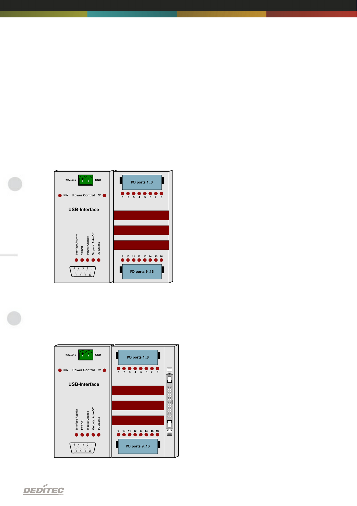
2.1. Overview screen
The figure below shows the control module with USB-interface (left side)
combined with an input/output module (right side). For a connection to the USB
bus, an adequate adapter module in form of a USB-stick is included.
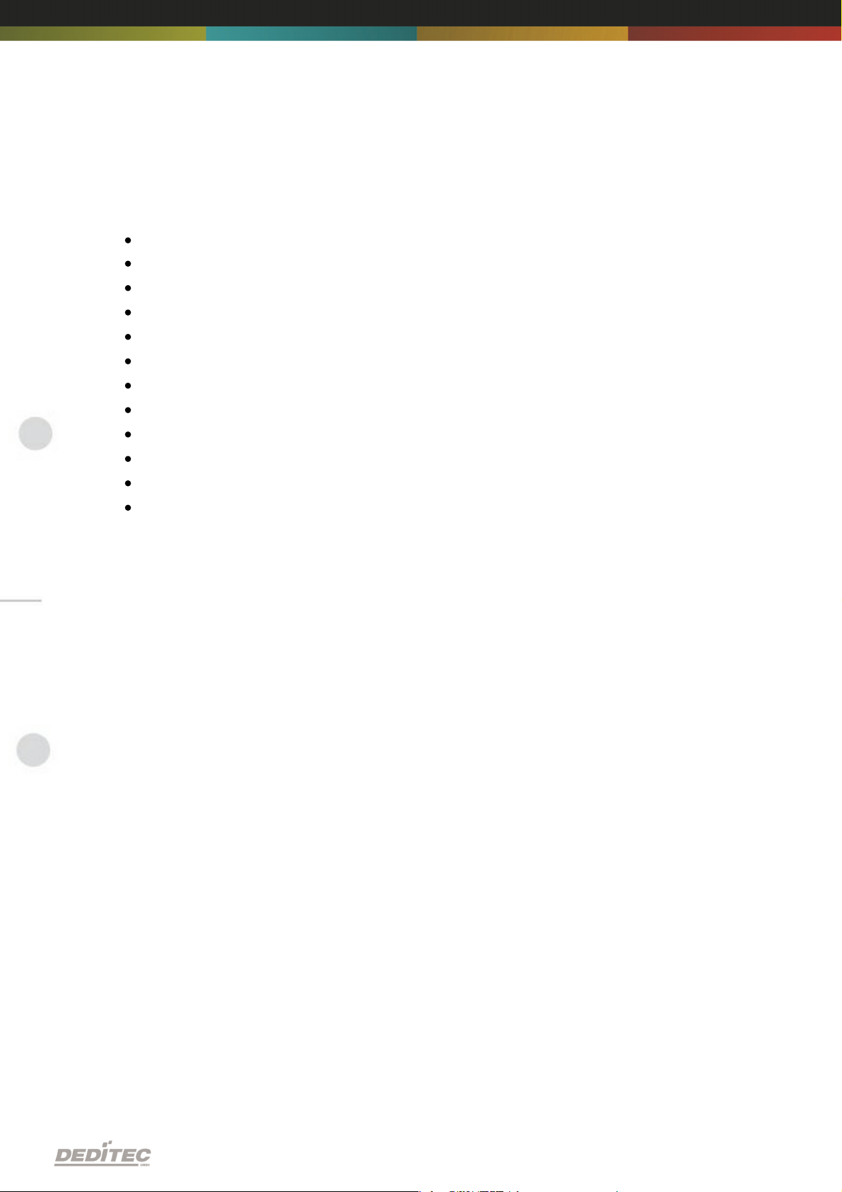
The figure below shows the control module with USB interface (left side)
combined with a flexible conntector input/output module (right side). For a
connection to the USB bus, an adequate adapter module in form of a USB-stick
is included with.
Hardware description |Seite 7
Page 8
2.2. Technical data
Single power supply +7V..+24V DC
7 control LEDs
USB interface
Transmission range up to 100m!
USB 2.0 and USB 1.1
Data transfer speed: 12 MBit/s or 1,5 MBit/s
Galvanically isolated interface using optocouplers
9 pol. D-SUB connector
Timeout feature providing ability to disconnect outputs for safety reasons
Comfortable connector system with ejection mechanism
Expandable in 16 gradations
Can be combined without any problem to other modules of the RO series
Hardware description |Seite 8
Page 9

2.3. Plug-in connector of the module
2.3.1. Power supply
The input-power-supply-range lies between +7V and +24V DC. Power supply
can be realized with a standard AC/DC adaptor with 1A output current. A
suitable plug-in connector is included.
2.3.2. USB interface
module in form of a USB stick with a connection cable. The stick has two
optocouplers ensuring a galvanical isolation to the PC.
The other end of the adapater is a 9 pol. D-SUB connector which is connected
to the RO-module.
Hardware description |Seite 9
Page 10
2.4. Control LEDs
LED
Description
3,3V
Internal 3,3V power supply
5V
Internal 5V power supply
Interface
Activity
Active communication- over the USB bus
ERROR
Error during USB-transfer (for details see document ”USB
protocol”)
Inputs:
Change
State change between 2 read-out cylces detected
Outputs:
Auto-Off
Due to timeout, all outputs are switched-off for safety
reasons
I/O Access
CPU-access on the inputs and outputs of the connected
modules
The USB module has a series of control LEDs. They are used for easy visual
indication of various state functions.
While switching-on the module, it should signalize the following sequence:
all five LEDs flashing briefly
right LED (I/O access) flashing briefly
all five LEDs flashing briefly
2.4.1. Definition of the LEDs
Hardware description |Seite 10
Page 11

Software
III
Software | Seite 11
Page 12

3. Software
3.1. Using our products
3.1.1. Access via graphical applications
We provide driverinterfaces e.g. for LabVIEW and ProfiLab. The DELIB driver
library is the basis, which can be directly activated by ProfiLAB.
For LabVIEW, we provide a simple driver connection with examples!
3.1.2. Access via the DELIB driver library
In the appendix, you can find the complete function reference for the integration
of our API-functions in your software. In addition we provide examples for the
following programming languages:
C
C++
C#
Delphi
VisualBasic
VB.NET
MS-Office
3.1.3. Access via protocol
The protocol for the activation of our products is open source. So you are able
to use our products on systems without Windows or Linux.
Software | Seite 12
Page 13

3.1.4. Access via provided test programs
We provide simple handling test programs for the most important functions of
our products. These will be installed automatically by the installation of the
DELIB driver library.
So you can test directly e.g. relays or you can check the voltage of an A/D
converter.
Software | Seite 13
Page 14

3.2. DELIB driver library
3.2.1. Overview
The following figure explains the structure of the DELIB driver library
The DELIB driver library allows an uniform response of DEDITEC hardware with
particular consideration of the following viewpoints:
Independent of operating system
Independent of programming language
Independent of the product
Program under diverse operating systems
The DELIB driver library allows an uniform response of our products on diverse
operating systems.
We has made sure, that all of our products can be responded by a few
commands.
Whatever which operating system you use. - Therefore the DELIB cares!
Software | Seite 14
Page 15

Program with diverse programming languages
We provide uniform commands to create own applications. This will be solved
by the DELIB driver library.
You choose the programming language!
It can be simply developed applications under C++, C, Visual Basic, Delphi or
LabVIEW®.
Program independent of the interface
Write your application independent of the interface !
Program an apllication for an USB product of us. - Also, it will work with an
ethernet or RS-232 product of us !
SDK-Kit for Programmer
Integrate the DELIB in your application. On demand you receive an installation
script for free, which allows you, to integrate the DELIB installation in your
apllication.
Software | Seite 15
Page 16
3.2.2. Supported operating systems
Our products support the following operating systems:
Windows 2000
Windows XP
Windows Vista
Windows 7
Linux
3.2.3. Supported programming languages
Our products are responsive via the following programming languages:
C
C++
C#
Delphi
VisualBasic
VB.NET
MS-Office
Software | Seite 16
Page 17
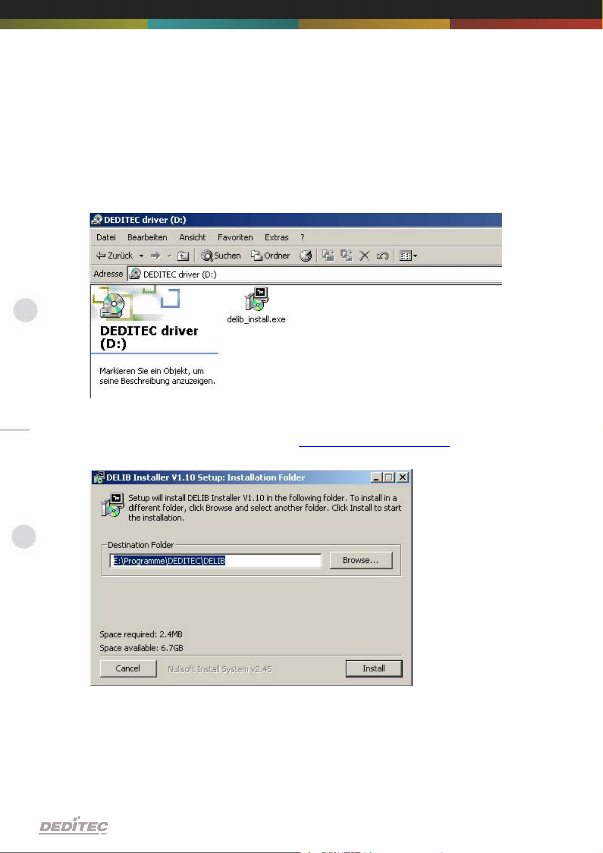
3.2.4. Installation DELIB driver library
DELIB stands for DEDITEC Library and contains the necessary libraries for the
modules in the programming languages C, Delphi and Visual Basic.
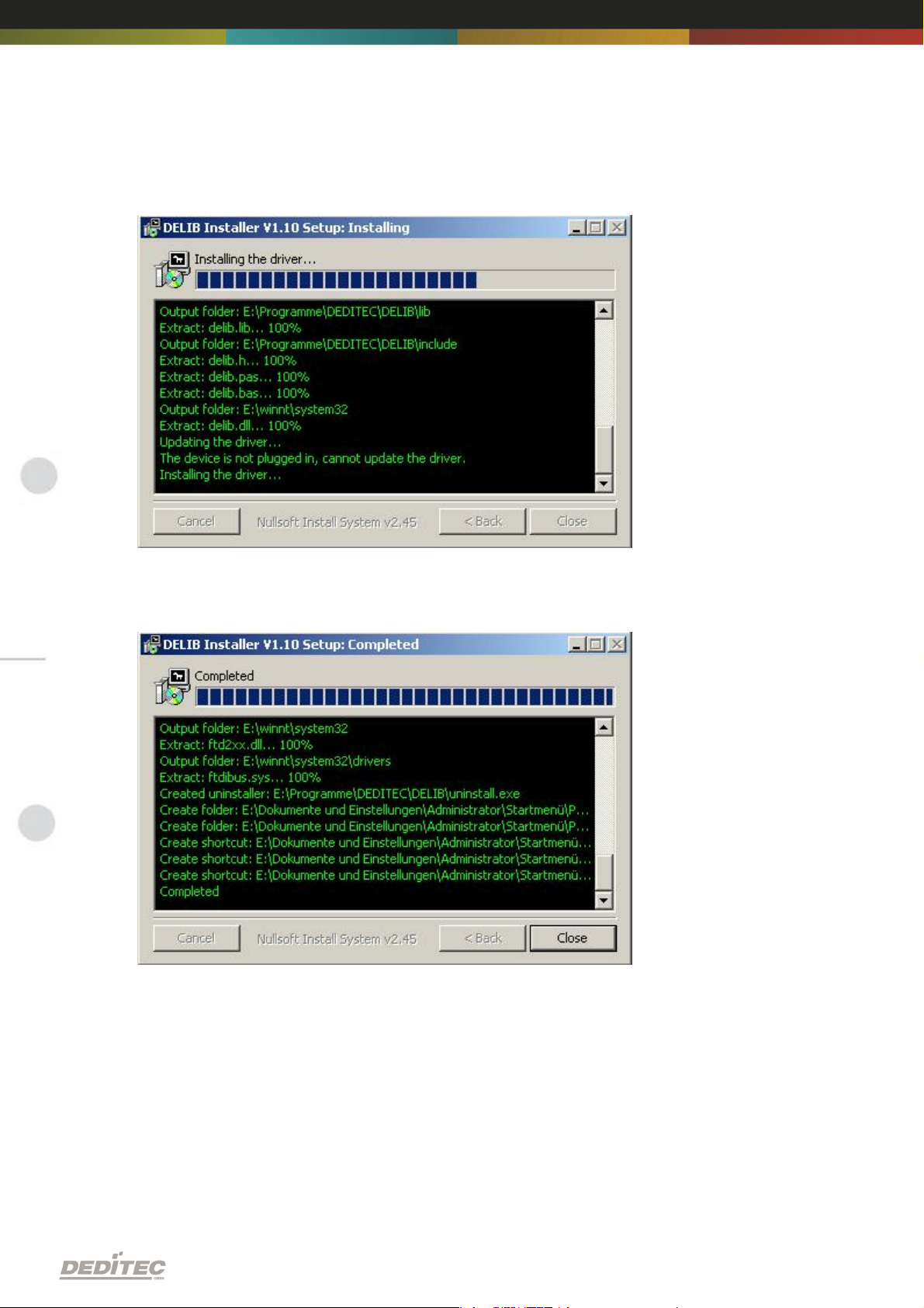
Insert the DEDITEC driver CD into the drive and start „delib_install.exe“. The
DELIB driver library is also available on http://www.deditec.en/delib
Click on „Install“.
Software | Seite 17
Page 18

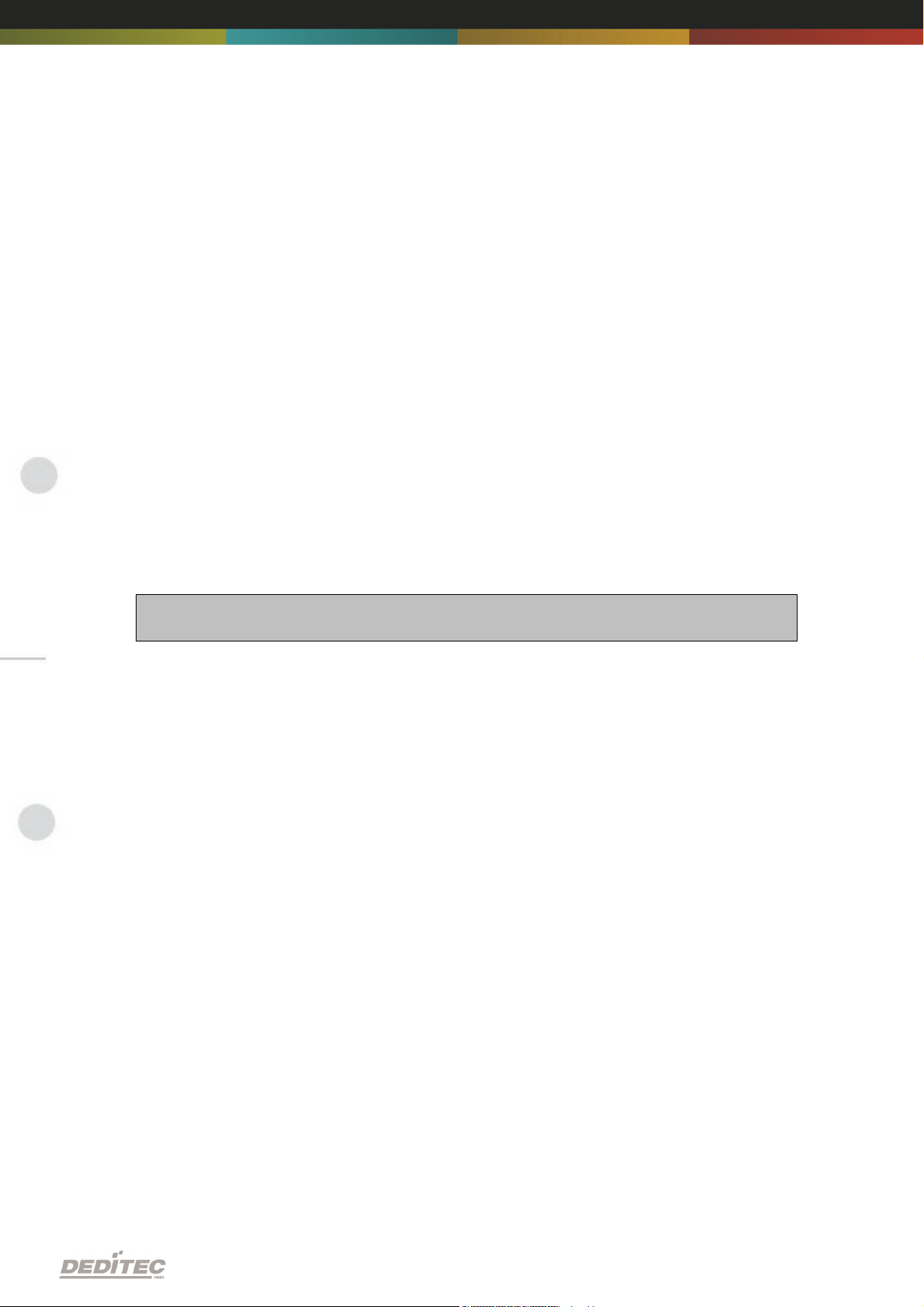
The drivers will be installed.
The DELIB driver library is now installed. Press „Close“ to finish the installation.
You can configure your module with the „DELIB Configuration Utility“ (see
next chapter). This is only necessary, if more than one module is present.
Software | Seite 18
Page 19

3.2.5. DELIB Configuration Utility
Start the “DELIB Configuration Utility” as follows:
Start Programs DEDITEC DELIB DELIB Configuration Utility.
The „DELIB Configuration Utility“ is a program to configure and subdivide
identical USB-modules in the system. This is only necessary if more than one
module is present.
Software | Seite 19
Page 20

3.3. Test programs
3.3.1. Digital Input-Output Demo
Start “Digital Input-Output Demo” as follows:
Start Programme DEDITEC DELIB Digital Input-Output Demo.
The screenshot shows a test of the RO-USB-O64-R64. The configuration of the
module (64 inputs and 64 outputs) is shown on the upper left side.
Software | Seite 20
Page 21

3.3.2. Analog Input-Output Demo
Start “Analog Input-Output Demo” as follows:
Start Programme DEDITEC DELIB Analog Input-Output Demo.
The screenshot shows a test of the RO-USB-AD16-DA2_ISO. The configuration
of the module (16 A/D inputs and 2 D/A outputs) is shown on the upper left side.
Software | Seite 21
Page 22

3.3.3. Stepper Demo
Start “Stepper Demo” as follows:
Start Programme DEDITEC DELIB Stepper Demo.
The screenshot shows a test of the RO-USB-STEPPER2. The configuration of
the module (2 Stepper) is shown on the upper left side.
Software | Seite 22
Page 23

Appendix
IV
Appendix | Seite 23
Page 24

4. Appendix
4.1. Revisions
Rev 1.00 First issue
Rev 2.00 Design change
Appendix | Seite 24
Page 25

4.2. Copyrights and trademarks
Linux is registered trade-mark of Linus Torvalds.
Windows CE is registered trade-mark of Microsoft Corporation.
USB is registered trade-mark of USB Implementers Forum Inc.
LabVIEW is registered trade-mark of National Instruments.
Intel is registered trade-mark of Intel Corporation
AMD is registered trade-mark of Advanced Micro Devices, Inc.
Appendix | Seite 25
Page 26

RO-DIGITAL-IN-OUT
Hardware-Description
2010
Oktober
Page 27
INDEX
1. Introduction 6
1.1. General remarks 6
1.2. Customer satisfaction 6
1.3. Customer response 6
2. Hardware description 8
2.1. Opto-coupler inputs 9
2.1.1. Overview screen
2.1.2. Technical data
2.1.3. 16-bit counter
2.1.4. Registering short input pulses
2.1.5. Galvanically decouppled through optocouplers
2.1.6. Plug-in connector on the module
2.1.6.1. Connection wiring
2.1.6.2. Visual control of the inputs
2.1.6.3. Pinout
2.1.7. Variable input voltage range
2.1.7.1. Changing the input voltage
10
11
11
11
12
12
13
13
13
14
2.2. Relay outputs 15
2.2.1. Overview screen
2.2.2. Technical data
2.2.3. Timeout-protection
2.2.4. Plug-in connector on the module
2.2.4.1. Relay-outputs (galvanically decoupled, max.
1A)
2.2.4.2. Connection wiring
2.2.4.3. Visual control of the outputs
2.2.4.4. Pinout
15
16
17
17
17
18
18
18
9
2.3. MOSFET outputs 19
2.3.1. Overview screen
2.3.2. Technical data
2.3.3. Timeout-protection
2.3.4. Plug-in connector on the module
19
20
21
21
Index | 2Seite
Page 28

INDEX
2.3.4.1. Optocoupler-outputs (galvanically isolated,
max. 2A DC)
2.3.4.2. Connection wiring
2.3.4.3. Pinout
3. Software 24
3.1. Using our products 24
21
22
22
3.1.1. Access via graphical applications
3.1.2. Access via the DELIB driver library
3.1.3. Access via protocol
3.1.4. Access via provided test programs
24
24
24
25
3.2. DELIB driver library 26
3.2.1. Overview
3.2.2. Supported operating systems
3.2.3. Supported programming languages
3.2.4. Installation DELIB driver library
3.2.5. DELIB Configuration Utility
26
28
28
29
31
3.3. Test programs 32
3.3.1. Digital Input-Output Demo
32
4. DELIB API reference 34
4.1. Management functions 34
4.1.1. DapiOpenModule
4.1.2. DapiCloseModule
4.2. Error handling 36
34
35
4.2.1. DapiGetLastError
4.2.2. DapiGetLastErrorText
36
37
4.3. Reading Digital inputs 38
4.3.1. DapiDIGet1
4.3.2. DapiDIGet8
4.3.3. DapiDIGet16
4.3.4. DapiDIGet32
4.3.5. DapiDIGet64
4.3.6. DapiDIGetFF32
4.3.7. DapiDIGetCounter
38
39
40
41
42
43
44
Index | 3Seite
Page 29
INDEX
4.4. Setting Digital outputs 45
4.4.1. DapiDOSet1
4.4.2. DapiDOSet8
4.4.3. DapiDOSet16
4.4.4. DapiDOSet32
4.4.5. DapiDOSet64
4.4.6. DapiDOReadback32
4.4.7. DapiDOReadback64
45
46
47
48
49
50
51
4.5. Output timeout management 52
4.5.1. DapiSpecialCMDTimeout
4.5.2. DapiSpecialCMDTimeoutGetStatus
52
53
4.6. Test functions 54
4.6.1. DapiPing
54
4.7. Example program 55
5. Appendix 58
5.1. Revisions 58
5.2. Copyrights and trademarks 59
Index | 4Seite
Page 30

Introduction
I
Introduction | Seite 5
Page 31

1. Introduction
1.1. General remarks
First of all, we would like to congratulate you to the purchase of a high quality
DEDITEC product.
Our products are being developed by our engineers according to quality
requirements of high standard. Already during design and development we take
care that our products have -besides quality- a long availability and an optimal
flexibility.
Modular design
The modular design of our products reduces the time and the cost of
development. Therefor we can offer you high quality products at a competitive
price.
Availability
Because of the modular design of our products, we have to redesign only a
module instead of the whole product, in case a specific component is no longer
available.
1.2. Customer satisfaction
Our philosophy: a content customer will come again. Therefor customer
satisfaction is in first place for us.
If by any chance, you are not content with the performance of our product,
please contact us by phone or mail immediately.
We take care of the problem.
1.3. Customer response
Our best products are co-developments together with our customers. Therefor
we are thankful for comments and suggestions.
Introduction | Seite 6
Page 32

Hardware description
II
Hardware description |Seite 7
Page 33

2. Hardware description
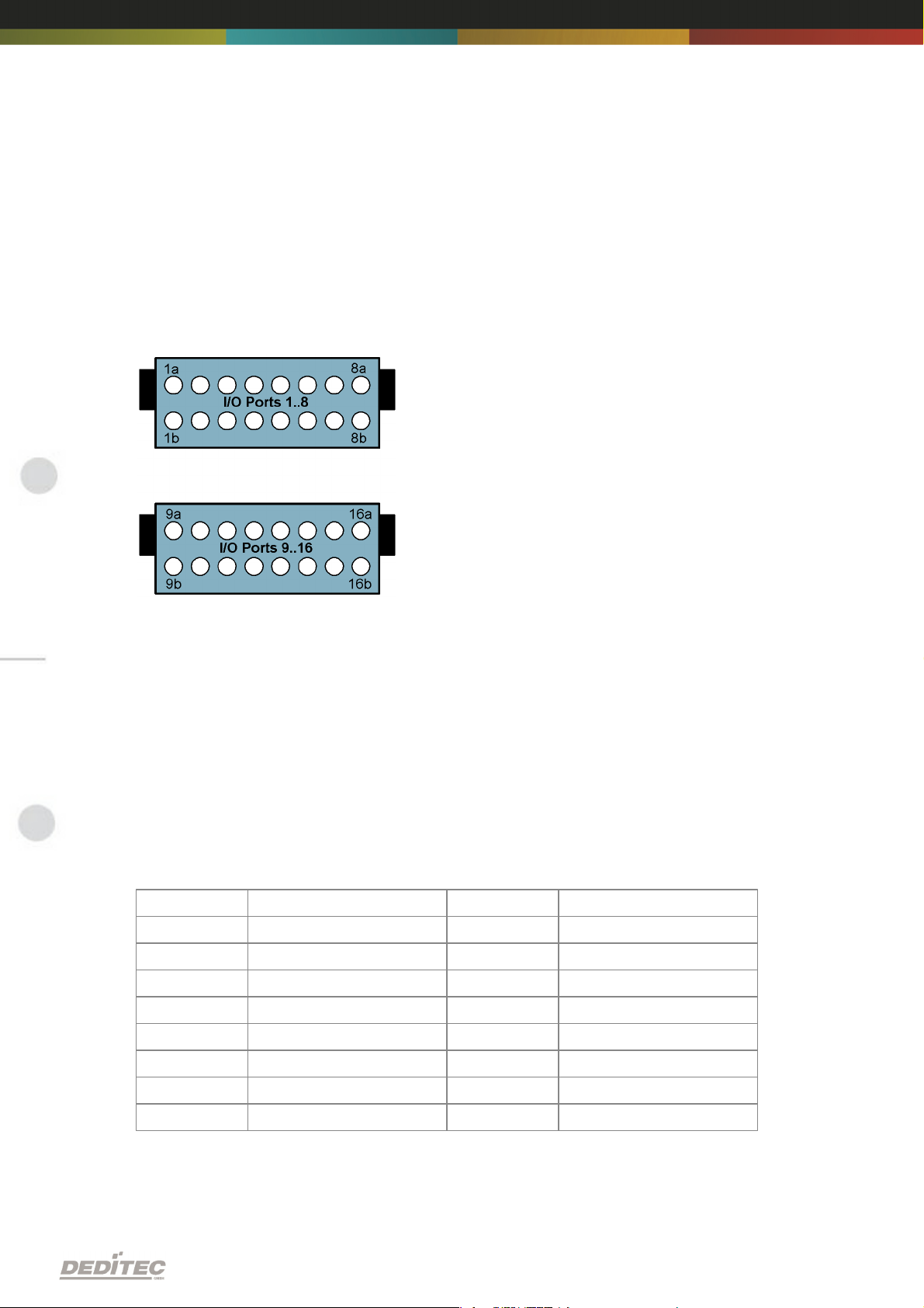
Using the in-/output modules is based on two 16 pol. connectors with each 8
different current circuits. Each state of these (total 16) current circuits is
signalized by a LED. The modules are numbered from left to right (see overview
screen).
Hardware description |Seite 8
Page 34

2.1. Opto-coupler inputs
2.1.1. Overview screen
The figure shows two modules next to each other with corresponding
numbering of the terminal blocks.
The lower figure shows a flexible conntector module with 32 outputs and
corresponding numbered ports. Each outer end of the module has a 26 pol. wire
trap connector. Thus, multiple modules can be connected in series using a
ribbon cable for each connection.
Hardware description |Seite 9
Page 35

2.1.2. Technical data
Variable power supply min. 5V, max. 30V AC
16-bit counter for the first 16 input channels
Pulse-detection between 2 read out cycles, indicated by LED
LED status indication of the inputs
Galvanically isolated using optocouplers
Comfortable connector system with ejection mechanism
Expandable in 16 gradations
Can be combined without any problem to other modules of the RO series
Hardware description |Seite 10
Page 36

2.1.3. 16-bit counter
The first 16 input channels have each a 16 bit counter. Thus, events as light
barriers, turnstiles or push-buttons are counted. Easy logical circuits are
realizable, which may e.g. switch one or several outputs, if a counter reached a
certain amount (set-point is reached). Please refer to the manual ”RO-series” to
implement such logical circuits into software.
2.1.4. Registering short input pulses
Short input pulses between to read-out cycles are registered through an
additional logic and can be separately read-out. A registered pulse on one or
more inputs is signalized by the LED ”Inputs: Change” on the control module.
The LED is extinguishing, if the software-register of the input state change is
read out by the user. For more indformation, see ”Register assignment”.
2.1.5. Galvanically decouppled through optocouplers
AC input optocouplers provide a galvanic isolation of the module towards the
connected equipment. They also provide a safe connection to the module for
reverse currents and high voltage peaks.
Hardware description |Seite 11
Page 37

2.1.6. Plug-in connector on the module
As terminal block, user-friendly terminal strips with locking protection and
ejection mechanism are used. They are reverse-polarity protected and allow
quick replugging. The wire connection itself is realised with a screwless
connector system. A tool is included with each module.
2.1.6.1. Connection wiring
Connecting the wires is to be effected at the ports with the same numbering, for
example: 1a & 1b, 2a & 2b. ...
The optocoupler inputs are suitable for AC voltage. Therefore it is not necessary
to take care of the connection polarity.
The figure shows two terminal blocks with numbered connection ports.
Hardware description |Seite 12
Page 38

2.1.6.2. Visual control of the inputs
Port
Pin
Port
Pin11a & 1b
9
9a & 9b
2
2a & 2b
10
10a & 10b
3
3a & 3b
11
11a & 11b
4
4a & 4b
12
12a & 12b
5
5a & 5b
13
13a & 13b
6
6a & 6b
14
14a & 14b
7
7a & 7b
15
15a & 15b
8
8a & 8b
16
16a & 16b
Input voltage range
5V – 15V
15V – 30V
Resistance value
1K
2K2
The state of each input is directly signalized by a separate LED. This simplifies
to detect and rectify wiring errors, because the signals on the cables are directly
observable.
2.1.6.3. Pinout
2.1.7. Variable input voltage range
The factory-default of the inputs is set to a voltage range of 15V to 30V. This
may be changed to a range of 5V to 15V (even afterward).
Hardware description |Seite 13
Page 39

2.1.7.1. Changing the input voltage
Each terminal block has 8 inputs sudivided in two groups and each group has its
own input voltage range (resulting groups: 1-4, 5-8, 9-12 und 13-16). Each
group‘s input voltage range is defined by a corresponding resistor network.
The following steps describes how to exchange one or more resistor networks.
Notice!
Bevore opening the device, please note the following:
Disconnect the power supply (unplug AC/DC adaptor)!
Do not touch electronic components. They could be destroyed by electrostatic
discharge! If necessary, touch grounded metal casings or radiators.
Remove a module‘s side element. Unscrew the three Phillips screws.
Pull the circuit board together with the front panel sideways out.
Lift the front panel from the module.
Every input module has two single rowed socket terminal strips in which the
resistor networks are plugged in. Please carefully remove the desired resistor
network and replace them it appropriate one.
Assembling the elements in done the reverse order.
Hardware description |Seite 14
Page 40

2.2. Relay outputs
2.2.1. Overview screen
The figure shows two modules next to each other with corresponding
numbering of the terminal blocks.
The lower figure shows a flexible conntector module with 32 outputs and
corresponding numbered ports. Each outer end of the module has a 26 pol. wire
trap connector. Thus, multiple modules can be connected in series using a
ribbon cable for each connection.
Hardware description |Seite 15
Page 41
2.2.2. Technical data
Timeout-protection
LED status indication of the outputs
Galvanically isolated using optocouplers
Comfortable connector system with ejection mechanism
Expandable in 16 gradations
Can be combined without any problem to other modules of the RO series
Max. switching voltage: 36V
Max. switching current: 1A
Max. switching power: 20W
Switching cycles according to the manufacturer: 10 Mio.
Hardware description |Seite 16
Page 42

2.2.3. Timeout-protection
The timeout-protection gives the possibility to switch-off automatically the
outputs on its own to prevent damage. This takes place, if in a predefined time
frame no communication with the module was possible. Reasons could be cable
disruption, PC-crash and more. This way damage control, surcharge of
connected equipment and risk of accidents can be avoided. Switching off the
outputs is indicated by a LED.
2.2.4. Plug-in connector on the module
As terminal block, user-friendly terminal strips with locking protection and
ejection mechanism are used. They are reverse-polarity protected and allow
quick replugging. The wire connection itself is realised with a screwless
connector system. A tool is included with each module.
2.2.4.1. Relay-outputs (galvanically decoupled, max. 1A)
The relays are able to switch voltages up to 36V. The max. current is 1A at a
max. power of 20W.
Additionally, the relays provide a safe electrical isolation of the module to the
connected equipment.
Hardware description |Seite 17
Page 43
2.2.4.2. Connection wiring
Port
Pin
Port
Pin11a & 1b
9
9a & 9b
2
2a & 2b
10
10a & 10b
3
3a & 3b
11
11a & 11b
4
4a & 4b
12
12a & 12b
5
5a & 5b
13
13a & 13b
6
6a & 6b
14
14a & 14b
7
7a & 7b
15
15a & 15b
8
8a & 8b
16
16a & 16b
Connecting the wires is to be effected at the ports with the same numbering, for
example: 1a & 1b, 2a & 2b. ...
It is not necessary to take care to the correct polarity.
2.2.4.3. Visual control of the outputs
The state of each output is directly signalized by a separate LED. This simplifies
to detect and rectify wiring errors, because the signals on the cables are directly
observable.
2.2.4.4. Pinout
Hardware description |Seite 18
Page 44

2.3. MOSFET outputs
2.3.1. Overview screen
The figure shows two modules next to each other with corresponding
numbering of the terminal blocks.
The lower figure shows a flexible conntector module with 32 outputs and
corresponding numbered ports. Each outer end of the module has a 26 pol. wire
trap connector. Thus, multiple modules can be connected in series using a
ribbon cable for each connection.
Hardware description |Seite 19
Page 45

2.3.2. Technical data
Timeout-protection
LED status indication of the outputs
Galvanically isolated using optocouplers
Comfortable connector system with ejection mechanism
Expandable in 16 gradations
Can be combined without any problem to other modules of the RO series
Max. switching voltage: 30V DC
Max. switching current: 2A DC
Max. switching power: 40W
Hardware description |Seite 20
Page 46

2.3.3. Timeout-protection
The timeout-protection gives the possibility to switch-off automatically the
outputs on its own to prevent damage. This takes place, if in a predefined time
frame no communication with the module was possible. Reasons could be cable
disruption, PC-crash and more. This way damage control, surcharge of
connected equipment and risk of accidents can be avoided. Switching off the
outputs is indicated by a LED.
2.3.4. Plug-in connector on the module
As terminal block, user-friendly terminal strips with locking protection and
ejection mechanism are used. They are reverse-polarity protected and allow
quick replugging. The wire connection itself is realised with a screwless
connector system. A tool is included with each module.
2.3.4.1. Optocoupler-outputs (galvanically isolated, max. 2A DC)
Every output is realized using high current optocouplers. Using optocouplers
provides a secure galvanical decoupling of the module-driven equipment to the
module itself.
Pay attention to the optocoupler’s output polarity while wiring (see figure below)!
Hardware description |Seite 21
Page 47

2.3.4.2. Connection wiring
Port
Pin
Port
Pin11a & 1b
9
9a & 9b
2
2a & 2b
10
10a & 10b
3
3a & 3b
11
11a & 11b
4
4a & 4b
12
12a & 12b
5
5a & 5b
13
13a & 13b
6
6a & 6b
14
14a & 14b
7
7a & 7b
15
15a & 15b
8
8a & 8b
16
16a & 16b
Connecting the wires is to be effected at the ports with the same numbering, for
example: 1a & 1b, 2a & 2b, ... Pay attention to the optocoupler’s output polarity
while wiring, else the outputs will get damaged. Connect the positive voltage to
port ”a”, and the switched positive voltage to port ”b”.
2.3.4.3. Pinout
Hardware description |Seite 22
Page 48

Software
III
Software | Seite 23
Page 49

3. Software
3.1. Using our products
3.1.1. Access via graphical applications
We provide driverinterfaces e.g. for LabVIEW and ProfiLab. The DELIB driver
library is the basis, which can be directly activated by ProfiLAB.
For LabVIEW, we provide a simple driver connection with examples!
3.1.2. Access via the DELIB driver library
In the appendix, you can find the complete function reference for the integration
of our API-functions in your software. In addition we provide examples for the
following programming languages:
C
C++
C#
Delphi
VisualBasic
VB.NET
MS-Office
3.1.3. Access via protocol
The protocol for the activation of our products is open source. So you are able
to use our products on systems without Windows or Linux.
Software | Seite 24
Page 50

3.1.4. Access via provided test programs
We provide simple handling test programs for the most important functions of
our products. These will be installed automatically by the installation of the
DELIB driver library.
So you can test directly e.g. relays or you can check the voltage of an A/D
converter.
Software | Seite 25
Page 51

3.2. DELIB driver library
3.2.1. Overview
The following figure explains the structure of the DELIB driver library
The DELIB driver library allows an uniform response of DEDITEC hardware with
particular consideration of the following viewpoints:
Independent of operating system
Independent of programming language
Independent of the product
Program under diverse operating systems
The DELIB driver library allows an uniform response of our products on diverse
operating systems.
We has made sure, that all of our products can be responded by a few
commands.
Whatever which operating system you use. - Therefore the DELIB cares!
Software | Seite 26
Page 52

Program with diverse programming languages
We provide uniform commands to create own applications. This will be solved
by the DELIB driver library.
You choose the programming language!
It can be simply developed applications under C++, C, Visual Basic, Delphi or
LabVIEW®.
Program independent of the interface
Write your application independent of the interface !
Program an apllication for an USB product of us. - Also, it will work with an
ethernet or RS-232 product of us !
SDK-Kit for Programmer
Integrate the DELIB in your application. On demand you receive an installation
script for free, which allows you, to integrate the DELIB installation in your
apllication.
Software | Seite 27
Page 53

3.2.2. Supported operating systems
Our products support the following operating systems:
Windows 2000
Windows XP
Windows Vista
Windows 7
Linux
3.2.3. Supported programming languages
Our products are responsive via the following programming languages:
C
C++
C#
Delphi
VisualBasic
VB.NET
MS-Office
Software | Seite 28
Page 54

3.2.4. Installation DELIB driver library
DELIB stands for DEDITEC Library and contains the necessary libraries for the
modules in the programming languages C, Delphi and Visual Basic.
Insert the DEDITEC driver CD into the drive and start „delib_install.exe“. The
DELIB driver library is also available on http://www.deditec.en/delib
Click on „Install“.
Software | Seite 29
Page 55
The drivers will be installed.
The DELIB driver library is now installed. Press „Close“ to finish the installation.
You can configure your module with the „DELIB Configuration Utility“ (see
next chapter). This is only necessary, if more than one module is present.
Software | Seite 30
Page 56

3.2.5. DELIB Configuration Utility
Start the “DELIB Configuration Utility” as follows:
Start Programs DEDITEC DELIB DELIB Configuration Utility.
The „DELIB Configuration Utility“ is a program to configure and subdivide
identical USB-modules in the system. This is only necessary if more than one
module is present.
Software | Seite 31
Page 57

3.3. Test programs
3.3.1. Digital Input-Output Demo
Start “Digital Input-Output Demo” as follows:
Start Programme DEDITEC DELIB Digital Input-Output Demo.
The screenshot shows a test of the RO-USB-O64-R64. The configuration of the
module (64 inputs and 64 outputs) is shown on the upper left side.
Software | Seite 32
Page 58

DELIB API reference
IV
DELIB API reference | Seite 33
Page 59

4. DELIB API reference
// USB-Modul öffnen
handle = DapiOpenModule(RO_USB1, 0);
printf("handle = %x\n", handle);
if (handle==0)
{
// USB Modul wurde nicht gefunden
printf("Modul konnte nicht geöffnet werden\n");
return;
}
4.1. Management functions
4.1.1. DapiOpenModule
Description
This function opens a particular module.
Definition
ULONG DapiOpenModule(ULONG moduleID, ULONG nr);
Parameters
moduleID=Specifies the module, which is to be opened (see delib.h)
nr=Indicates No of module which is to be opened.
nr=0 -> 1. module
nr=1 -> 2. module
Return value
handle=handle to the corresponding module
handle=0 -> Module was not found
Remarks
The handle returned by this function is needed to identify the module for all
other functions.
Example program
DELIB API reference | Seite 34
Page 60
4.1.2. DapiCloseModule
// Close the module
DapiCloseModule(handle);
Description
This command closes an opened module.
Definition
ULONG DapiCloseModule(ULONG handle);
Parameters
handle=This is the handle of an opened module
Return value
none
Example program
DELIB API reference | Seite 35
Page 61

4.2. Error handling
ULONG error;
error=DapiGetLastError();
if(error==0) return FALSE;
printf("ERROR = %d", error);
4.2.1. DapiGetLastError
Description
This function returns the last registered error.
Definition
ULONG DapiGetLastError();
Parameters
None
Return value
Error code
0=no error. (see delib.h)
Example program
DELIB API reference | Seite 36
Page 62
4.2.2. DapiGetLastErrorText
BOOL IsError ()
{
if (DapiGetLastError () != DAPI_ERR_NONE)
{
unsigned char msg[500];
DapiGetLastErrorText((unsigned char*) msg, sizeof(msg));
printf ("Error Code = %x * Message = %s\n", 0, msg);
return TRUE;
}
return FALSE;
}
Description
This function reads the text of the last registered error.
Definition
extern ULONG __stdcall DapiGetLastErrorText(unsigned char * msg, unsigned long msg_length);
Parameters
msg = text buffer
msg_length = length of the buffer
Example program
DELIB API reference | Seite 37
Page 63

4.3. Reading Digital inputs
4.3.1. DapiDIGet1
Description
This command reads a single digit input.
Definition
ULONG DapiDIGet1(ULONG handle, ULONG ch);
Parameters
handle=This is the handle of an opened module.
ch=Specifies the number of input that is to be read (0 ..).
Return value
State of the input (0 / 1).
DELIB API reference | Seite 38
Page 64

4.3.2. DapiDIGet8
Description
This command reads 8 digital inputs simultaneously.
Definition
ULONG DapiDIGet8(ULONG handle, ULONG ch);
Parameters
handle=This is the handle of an opened module.
ch=Specifies the number of the input, from which it begins to read from (0, 8,
16, 24, 32, ..)
Return value
State of the read inputs.
DELIB API reference | Seite 39
Page 65

4.3.3. DapiDIGet16
Description
This command reads 16 digital inputs simultaneously.
Definition
ULONG DapiDIGet16(ULONG handle, ULONG ch);
Parameters
handle=This is the handle of an opened module.
ch=Specifies the number of the input, from which it begins to read from (0, 16,
32, ..)
Return value
State of the read inputs.
DELIB API reference | Seite 40
Page 66

4.3.4. DapiDIGet32
unsigned long data;
// ---------------------------------------------------// Einen Wert von den Eingängen lesen (Eingang 1-31)
data = (unsigned long) DapiDIGet32(handle, 0);
// Chan Start = 0
printf("Eingang 0-31 : 0x%x\n", data);
printf("Taste für weiter\n");
getch();
// ---------------------------------------------------// Einen Wert von den Eingängen lesen (Eingang 32-64)
data = (unsigned long) DapiDIGet32(handle, 32);
// Chan Start = 32
printf("Eingang 32-64 : 0x%x\n", data);
printf("Taste für weiter\n");
getch();
Description
This command reads 32 digital inputs simultaneously.
Definition
ULONG DapiDIGet32(ULONG handle, ULONG ch);
Parameters
handle=This is the handle of an opened module.
ch=Specifies the number of the input, from which it begins to read from (0, 32,
64, ..)
Return value
State of the read inputs.
Example program
DELIB API reference | Seite 41
Page 67

4.3.5. DapiDIGet64
Description
This command reads 64 digital inputs simultaneously.
Definition
ULONGLONG DapiDIGet64(ULONG handle, ULONG ch);
Parameters
handle=This is the handle of an opened module.
ch=Specifies the number of the input,from which it begins to read from (0, 64, ..)
Return value
State of the read inputs.
DELIB API reference | Seite 42
Page 68

4.3.6. DapiDIGetFF32
Description
This command reads the flip-flops from the inputs and resets them. (Input state
change).
Definition
ULONGLONG DapiDIGet64(ULONG handle, ULONG ch);
Parameters
handle=This is the handle of an opened module .
ch=Specifies the number of the input, from which it begins to read from (0, 32,
..)
Return value
State of 32 input change states
DELIB API reference | Seite 43
Page 69

4.3.7. DapiDIGetCounter
value = DapiDIGetCounter(handle, 0 ,0);
// Reading counter of DI Chan 0
value = DapiDIGetCounter(handle, 1 ,0);
// Reading counter of DI Chan 1
value = DapiDIGetCounter(handle, 8 ,0);
// Reading counter of DI Chan 8
value = DapiDIGetCounter(handle, 0 ,DAPI_CNT_MODE_READ_WITH_RESET);
// Reading AND resetting counter of DI Chan 0
Description
This command reads the counter of a digital input
Definition
ULONG DapiDIGetCounter(handle, ch, par1);
Parameters
handle=This is the handle of an opened module.
ch=Specifies the digital input, from which the counter will be read
par1=0 (Normal counter function)
par1=DAPI_CNT_MODE_READ_WITH_RESET (Reading and resetting the
counter)
Return value
Value of the counter.
Example program
DELIB API reference | Seite 44
Page 70

4.4. Setting Digital outputs
4.4.1. DapiDOSet1
Description
This is the command to set a single output.
Definition
void DapiDOSet1(ULONG handle, ULONG ch, ULONG data);
Parameters
handle=This is the handle of an opened module
ch=Specifies the number of the output to be set to (0 ..)
data=Specifies the data value that is to be written (0 / 1)
Return value
None
DELIB API reference | Seite 45
Page 71

4.4.2. DapiDOSet8
Description
This command sets 8 digital outputs simultaneously.
Definition
void DapiDOSet8(ULONG handle, ULONG ch, ULONG data);
Parameters
handle=This is the handle of an opened module
ch=Specifies the number of the output, from which it begins to write to (0, 8, 16,
24, 32, ..)
data=Specifies the data values, to write to the outputs
Return value
None
DELIB API reference | Seite 46
Page 72

4.4.3. DapiDOSet16
Description
This command sets 16 digital outputs simultaneously.
Definition
void DapiDOSet16(ULONG handle, ULONG ch, ULONG data);
Parameters
handle=This is the handle of an opened module
ch=Specifies the number of the output, from which it begins to write to (0, 16,
32, ..)
data=Specifies the data values, to write to the outputs
Return value
None
DELIB API reference | Seite 47
Page 73

4.4.4. DapiDOSet32
// Einen Wert auf die Ausgänge schreiben
data = 0x0000ff00; // Ausgänge 9-16 werden auf 1 gesetzt
DapiDOSet32(handle, 0, data); // Chan Start = 0
printf("Schreibe auf Ausgänge Daten=0x%x\n", data);
printf("Taste für weiter\n");
getch();
// ---------------------------------------------------// Einen Wert auf die Ausgänge schreiben
data = 0x80000000; // Ausgang 32 wird auf 1 gesetzt
DapiDOSet32(handle, 0, data); // Chan Start = 0
printf("Schreibe auf Ausgänge Daten=0x%x\n", data);
printf("Taste für weiter\n");
getch();
// ---------------------------------------------------// Einen Wert auf die Ausgänge schreiben
data = 0x80000000; // Ausgang 64 wird auf 1 gesetzt
DapiDOSet32(handle, 32, data); // Chan Start = 32
printf("Schreibe auf Ausgänge Daten=0x%x\n", data);
printf("Taste für weiter\n");
getch();
Description
This command sets 32 digital outputs simultaneously.
Definition
void DapiDOSet32(ULONG handle, ULONG ch, ULONG data);
Parameters
handle=This is the handle of an opened module
ch=Specifies the number of the output, from which it begins to write to (0, 32,
64, ..)
data=Specifies the data values, to write to the outputs
Return value
None
Example program
DELIB API reference | Seite 48
Page 74

4.4.5. DapiDOSet64
Description
This command is to set 64 digital outputs.
Definition
void DapiDOSet64(ULONG handle, ULONG ch, ULONG data);
Parameters
handle=This is the handle of an opened module
ch=Specifies the number of the output, from which it begins to write to (0, 64, ..)
data=Specifies the data values, to write to the outputs
Return value
None
DELIB API reference | Seite 49
Page 75

4.4.6. DapiDOReadback32
Description
This command reads back the 32 digital outputs.
Definition
ULONG DapiDOReadback32(ULONG handle, ULONG ch);
Parameters
handle=This is the handle of an opened module
ch=Specifies the number of the input, from which it begins to read from (0, 32,
..)
Return value
Status of 32 outputs.
DELIB API reference | Seite 50
Page 76

4.4.7. DapiDOReadback64
Description
This command reads back the 64 digital outputs.
Definition
ULONGLONG DapiDOReadback64(ULONG handle, ULONG ch);
Parameters
handle=This is the handle of an opened module
ch=Specifies the number of the input, from which it begins to read from (0, 64,
..)
Return value
Status of 64 outputs.
DELIB API reference | Seite 51
Page 77

4.5. Output timeout management
DapiSpecialCommand(handle, DAPI_SPECIAL_CMD_TIMEOUT,
DAPI_SPECIAL_TIMEOUT_SET_VALUE_SEC, 3, 7);
//Die Zeit des Timeouts wird auf 3,7sek gesetzt.
DapiSpecialCommand(handle, DAPI_SPECIAL_CMD_TIMEOUT,
DAPI_SPECIAL_TIMEOUT_ACTIVATE, 0, 0);
//Der Timeout wird aktiviert.
DapiSpecialCommand(handle, DAPI_SPECIAL_CMD_TIMEOUT,
DAPI_SPECIAL_TIMEOUT_DEACTIVATE, 0, 0);
//Der Timeout wird deaktiviert.
4.5.1. DapiSpecialCMDTimeout
Description
This command serves to set the timeout time
Definition
DapiSpecialCommand(handle, DAPI_SPECIAL_CMD_TIMEOUT, cmd, par1, par2);
Parameters
handle=This is the handle of an opened module
Set timeout time
cmd=DAPI_SPECIAL_CMD_TIMEOUT_SET_VALUE_SEC
par1=Seconds [s]
par2=Milliseconds [100ms] (value 6 stands for 600ms)
Activate timeout
cmd=DAPI_SPECIAL_CMD_TIMEOUT_ACTIVATE
Deactivate timeout
cmd=DAPI_SPECIAL_CMD_TIMEOUT_DEACTIVATE
Return value
None
Example program
DELIB API reference | Seite 52
Page 78
4.5.2. DapiSpecialCMDTimeoutGetStatus
status = DapiSpecialCommand(handle, DAPI_SPECIAL_CMD_TIMEOUT,
DAPI_SPECIAL_TIMEOUT_GET_STATUS, 0, 0); //Abfrage des Timeout-Status.
Description
This command reads the timeout status.
Definition
ULONG DapiSpecialCommand(handle, DAPI_SPECIAL_CMD_TIMEOUT,
DAPI_SPECIAL_TIMEOUT_GET_STATUS, 0, 0);
Parameters
handle=This is the handle of an opened module
Return value
Return=0 (timeout is deactivated)
Return=1 (timeout is activated)
Return=2 (timeout has occurred)
Example program
DELIB API reference | Seite 53
Page 79

4.6. Test functions
4.6.1. DapiPing
Description
This command checks the connection of an opened module.
Definition
ULONG DapiPing(ULONG handle, ULONG value);
Parameters
handle=This is the handle of an opened module
value=Given test value to the module
Return value
The given test-value “value“ is also the return value
DELIB API reference | Seite 54
Page 80

4.7. Example program
// ****************************************************************************
// ****************************************************************************
// ****************************************************************************
// ****************************************************************************
// ****************************************************************************
//
// (c) DEDITEC GmbH, 2009
//
// web: http://www.deditec.de
//
// mail: vertrieb@deditec.de
//
//
//
// dtapi_prog_beispiel_input_output.cpp
//
//
// ****************************************************************************
// ****************************************************************************
// ****************************************************************************
// ****************************************************************************
// ****************************************************************************
//
//
// Folgende Bibliotheken beim Linken mit einbinden: delib.lib
// Dies bitte in den Projekteinstellungen (Projekt/Einstellungen/Linker(ObjektBibliothek-Module) .. letzter Eintrag konfigurieren
#include <windows.h>
#include <stdio.h>
#include "conio.h"
#include "delib.h"
// ---------------------------------------------------------------------------// ---------------------------------------------------------------------------// ---------------------------------------------------------------------------// ---------------------------------------------------------------------------// ----------------------------------------------------------------------------
void main(void)
{
unsigned long handle;
unsigned long data;
unsigned long anz;
unsigned long i;
unsigned long chan;
// ---------------------------------------------------// USB-Modul öffnen
handle = DapiOpenModule(USB_Interface8,0);
printf("USB_Interface8 handle = %x\n", handle);
if (handle==0)
{
// USB Modul wurde nicht gefunden
printf("Modul konnte nicht geöffnet werden\n");
printf("TASTE für weiter\n");
getch();
DELIB API reference | Seite 55
Page 81

return;
}
// Zum Testen - ein Ping senden
// ---------------------------------------------------printf("PING\n");
anz=10;
for(i=0;i!=anz;++i)
{
data=DapiPing(handle, i);
if(i==data)
{
// OK
printf(".");
}
else
{
// No answer
printf("E");
}
}
printf("\n");
// ---------------------------------------------------// Einen Wert auf die Ausgänge schreiben
data = 255;
DapiWriteByte(handle, 0, data);
printf("Schreibe auf Adresse=0 daten=0x%x\n", data);
// ---------------------------------------------------// Einen Wert auf die Ausgänge schreiben
data = 255;
DapiWriteByte(handle, 1, data);
printf("Schreibe auf Adresse=0 daten=0x%x\n", data);
// ---------------------------------------------------// Einen Wert auf die Ausgänge schreiben
data = 255;
DapiWriteByte(handle, 2, data);
printf("Schreibe auf Adresse=2 daten=0x%x\n", data);
// ---------------------------------------------------// Einen Wert von den Eingängen lesen
data = (unsigned long) DapiReadByte(handle, 0);
printf("Gelesene Daten = 0x%x\n", data);
// ---------------------------------------------------// Einen A/D Wert lesen
chan=11; // read chan. 11
data = DapiReadWord(handle, 0xff010000 + chan*2);
printf("Adress=%x, ret=%x volt=%f\n", chan, data, ((float) data) / 1024*5);//
Bei 5 Volt Ref
// ---------------------------------------------------// Modul wieder schliessen
DapiCloseModule(handle);
printf("TASTE für weiter\n");
getch();
return ;
}
DELIB API reference | Seite 56
Page 82

Appendix
V
Appendix | Seite 57
Page 83

5. Appendix
5.1. Revisions
Rev 1.00 First issue
Rev 2.00 Design change
Appendix | Seite 58
Page 84

5.2. Copyrights and trademarks
Linux is registered trade-mark of Linus Torvalds.
Windows CE is registered trade-mark of Microsoft Corporation.
USB is registered trade-mark of USB Implementers Forum Inc.
LabVIEW is registered trade-mark of National Instruments.
Intel is registered trade-mark of Intel Corporation
AMD is registered trade-mark of Advanced Micro Devices, Inc.
Appendix | Seite 59
Page 85

RO-Series
Hardware-Description
2010
November
Page 86

INDEX
1. Introduction 10
1.1. General remarks 10
1.2. Customer satisfaction 10
1.3. Customer response 10
2. Hardware description 12
2.1. Ethernet Interface 12
2.1.1. Hardware description
2.1.1.1. Overview screen
2.1.1.2. Technical data
2.1.1.3. Plug-in connector of the module
2.1.1.3.1. Power supply
2.1.1.3.2. Ethernet interface
2.1.1.4. Buttons of the module
2.1.1.5. Controll LEDs
2.1.1.5.1. Definition of LEDs
2.1.2. Restore basic configuration
2.1.2.1. Restore IP address
2.1.2.2. Restore firmware
2.1.3. Firmware Update
2.1.3.1. DEDITEC Flasher
2.1.3.2. Web interface
2.1.4. Configuring the module
2.1.4.1. Configuration via DELIB Configuration utility
2.1.4.2. Configuration via internal web server
2.1.4.3. Factory settings
12
12
14
15
15
15
16
17
17
18
18
18
19
19
20
22
22
26
27
2.2. CAN Interface 28
2.2.1. Hardware description
2.2.1.1. Overview screen
2.2.1.2. Technical data
2.2.1.3. Plug-in connector of the module
2.2.1.3.1. Power supply
2.2.1.3.2. CAN interface
2.2.1.4. Control LEDs
2.2.1.4.1. Definition of LEDs
Index |
28
28
29
30
30
30
31
31
2Seite
Page 87

INDEX
2.2.2. Configuring the module
2.2.2.1. DIP-switches
2.2.2.2. The “special mode”
2.2.2.3. Software mode
2.2.2.4. DIP-switch mode
2.2.2.4.1. Setting up the transfer rate
2.2.2.4.2. Setting up the CAN module address
32
32
33
34
36
36
37
2.3. RS-232/RS-485 Interface 39
2.3.1. Hardware description
2.3.1.1. Overview screen
2.3.1.2. Technical data
2.3.1.3. Selecting between RS-232 or RS-485 interface
2.3.1.4. Plug-in connector of the module
2.3.1.4.1. Power supply
2.3.1.4.2. RS-232/RS-485 Interface
2.3.1.4.2.1RS-232 Pinout
2.3.1.4.2.2RS-485 Pinout
2.3.1.5. Control LEDs
2.3.1.5.1. Definition of LEDs
2.3.2. Configuring the module
2.3.2.1. DIP-switches
2.3.2.2. The "special-mode"
2.3.2.3. Activating echo
2.3.2.4. Setting up Baud rate
2.3.2.5. Setting up module address (RS-485 only)
39
39
40
41
43
43
43
44
44
45
45
46
46
47
47
48
49
2.4. USB Interface 50
2.4.1. Hardware description
2.4.1.1. Overview screen
2.4.1.2. Technical data
2.4.1.3. Plug-in connector of the module
2.4.1.3.1. Power supply
2.4.1.3.2. USB interface
2.4.1.4. Control LEDs
2.4.1.4.1. Definition of the LEDs
50
50
51
52
52
52
53
53
2.5. Digital in-/output modules 54
2.5.1. Hardware description
2.5.1.1. Opto-coupler inputs
54
55
Index |
3Seite
Page 88

INDEX
2.5.1.1.1. Overview screen
2.5.1.1.2. Technical data
2.5.1.1.3. 16-bit counter
2.5.1.1.4. Registering short input pulses
2.5.1.1.5. Galvanically decouppled through optocouplers
2.5.1.1.6. Plug-in connector on the module
2.5.1.1.6.1Connection wiring
2.5.1.1.6.2Visual control of the inputs
2.5.1.1.6.3Pinout
2.5.1.1.7. Variable input voltage range
2.5.1.1.7.1Changing the input voltage
2.5.1.2. Relay outputs
2.5.1.2.1. Overview screen
2.5.1.2.2. Technical data
2.5.1.2.3. Timeout-protection
2.5.1.2.4. Plug-in connector on the module
2.5.1.2.4.1Relay-outputs (galvanically decoupled, max. 1A)
2.5.1.2.4.2Connection wiring
2.5.1.2.4.3Visual control of the outputs
2.5.1.2.4.4Pinout
2.5.1.3. MOSFET outputs
2.5.1.3.1. Overview screen
2.5.1.3.2. Technical data
2.5.1.3.3. Timeout-protection
2.5.1.3.4. Plug-in connector on the module
2.5.1.3.4.1Optocoupler-outputs (galvanically isolated, max. 2A DC)
2.5.1.3.4.2Connection wiring
2.5.1.3.4.3Pinout
55
56
57
57
57
58
58
59
59
59
60
61
61
62
63
63
63
64
64
64
65
65
66
67
67
67
68
68
2.6. Analog in-/output modules 69
2.6.1. Hardware description
2.6.1.1. RO-AD16-DA4
2.6.1.1.1. Overview screen
2.6.1.1.2. Technical data
2.6.1.1.3. Timeout-protection
2.6.1.1.4. Pinout
2.6.1.1.4.1A/D connection wiring (18pol)
2.6.1.1.4.2D/A connection wiring (10pol)
2.6.1.2. RO-AD16
2.6.1.2.1. Overview screen
69
69
70
71
72
73
73
73
74
74
Index |
4Seite
Page 89

INDEX
2.6.1.2.2. Technical data
2.6.1.2.3. Pinout
2.6.1.2.3.1A/D connection wiring (18pol)
2.6.1.3. RO-AD16_ISO
2.6.1.3.1. Overview screen
2.6.1.3.2. Technical data
2.6.1.3.3. Pinout
2.6.1.3.3.1A/D connection wiring (18pol)
2.6.1.4. RO-DA4
2.6.1.4.1. Overview screen
2.6.1.4.2. Technical data
2.6.1.4.3. Timeout-protection
2.6.1.4.4. Pinout
2.6.1.4.4.1D/A connection wiring (10pol)
2.6.1.5. RO-DA2_ISO
2.6.1.5.1. Overview screen
2.6.1.5.2. Technical data
2.6.1.5.3. Timeout-protection
2.6.1.5.4. Pinout
2.6.1.5.4.1D/A connection wiring (10pol)
75
76
76
77
77
78
79
79
80
80
81
82
82
82
83
83
84
85
86
86
2.7. Stepper module 87
2.7.1. Hardware description
2.7.1.1. Overview screen
2.7.1.2. Technical data
2.7.1.3. Stepping motor control
2.7.1.4. Stepper connection wiring (10pol) - pinout
87
87
88
88
89
3. Software 91
3.1. Using our products 91
3.1.1. Access via graphical applications
3.1.2. Access via the DELIB driver library
3.1.3. Access via protocol
3.1.4. Access via provided test programs
3.2. DELIB driver library 93
3.2.1. Overview
3.2.2. Supported operating systems
3.2.3. Supported programming languages
91
91
91
92
93
95
95
Index |
5Seite
Page 90

INDEX
3.2.4. Installation DELIB driver library
3.2.5. DELIB Configuration Utility
96
98
3.3. Test programs 99
3.3.1. Digital Input-Output Demo
3.3.2. Analog Input-Output Demo
3.3.3. Stepper Demo
99
100
101
4. DELIB API reference 103
4.1. Management functions 103
4.1.1. DapiOpenModule
4.1.2. DapiCloseModule
4.2. Error handling 105
4.2.1. DapiGetLastError
4.2.2. DapiGetLastErrorText
4.3. Reading Digital inputs 107
4.3.1. DapiDIGet1
4.3.2. DapiDIGet8
4.3.3. DapiDIGet16
4.3.4. DapiDIGet32
4.3.5. DapiDIGet64
4.3.6. DapiDIGetFF32
4.3.7. DapiDIGetCounter
4.4. Setting Digital outputs 114
103
104
105
106
107
108
109
110
111
112
113
4.4.1. DapiDOSet1
4.4.2. DapiDOSet8
4.4.3. DapiDOSet16
4.4.4. DapiDOSet32
4.4.5. DapiDOSet64
4.4.6. DapiDOReadback32
4.4.7. DapiDOReadback64
114
115
116
117
118
119
120
4.5. A/D converter functions 121
4.5.1. DapiADSetMode
4.5.2. DapiADGetMode
4.5.3. DapiADGet
121
123
124
Index |
6Seite
Page 91

INDEX
4.5.4. DapiADGetVolt
4.5.5. DapiADGetmA
125
126
4.6. D/A outputs management 127
4.6.1. DapiDASetMode
4.6.2. DapiDAGetMode
4.6.3. DapiDASet
4.6.4. DapiDASetVolt
4.6.5. DapiDASetmA
4.6.6. DapiSpecialCmd_DA
127
129
130
131
132
133
4.7. Stepper motor functions 135
4.7.1. DapiStepperCommands
4.7.1.1. DAPI_STEPPER_CMD_GO_POSITION
4.7.1.2.
DAPI_STEPPER_CMD_GO_POSITION_RELATIVE
4.7.1.3. DAPI_STEPPER_CMD_SET_POSITION
4.7.1.4. DAPI_STEPPER_CMD_SET_FREQUENCY
4.7.1.5. DAPI_STEPPER_CMD_GET_FREQUENCY
4.7.1.6.
DAPI_STEPPER_CMD_SET_FREQUENCY_DIRECTLY
4.7.1.7. DAPI_STEPPER_CMD_STOP
4.7.1.8. DAPI_STEPPER_CMD_FULLSTOP
4.7.1.9. DAPI_STEPPER_CMD_DISABLE
4.7.1.10.
DAPI_STEPPER_CMD_SET_MOTORCHARACTERISTIC
4.7.1.11.
DAPI_STEPPER_CMD_GET_MOTORCHARACTERISTIC
4.7.1.12.
DAPI_STEPPER_CMD_MOTORCHARACTERISTIC_EEP
ROM_SAVE
4.7.1.13.
DAPI_STEPPER_CMD_MOTORCHARACTERISTIC_EEP
ROM_LOAD
4.7.1.14.
DAPI_STEPPER_CMD_MOTORCHARACTERISTIC_LOA
D_DEFAULT
4.7.1.15. DAPI_STEPPER_CMD_GO_REFSWITCH
4.7.1.16. DAPI_STEPPER_CMD_GET_CPU_TEMP
4.7.1.17.
DAPI_STEPPER_CMD_GET_MOTOR_SUPPLY_VOLTAG
E
135
135
136
137
138
139
140
141
142
143
144
149
157
158
159
160
161
162
Index |
7Seite
Page 92

INDEX
4.7.2. DapiStepperGetStatus
4.7.2.1. DAPI_STEPPER_STATUS_GET_ACTIVITY
4.7.2.2. DAPI_STEPPER_STATUS_GET_POSITION
4.7.2.3. DAPI_STEPPER_STATUS_GET_SWITCH
4.7.3. DapiStepperCommandEx
163
163
164
165
166
4.8. Output timeout management 167
4.8.1. DapiSpecialCMDTimeout
4.8.2. DapiSpecialCMDTimeoutGetStatus
167
168
4.9. Test functions 169
4.9.1. DapiPing
169
4.10. Example program 170
5. Appendix 173
5.1. Revisions 173
5.2. Copyrights and trademarks 174
Index |
8Seite
Page 93

Introduction
I
Introduction |
Seite 9
Page 94

1. Introduction
1.1. General remarks
First of all, we would like to congratulate you to the purchase of a high quality
DEDITEC product.
Our products are being developed by our engineers according to quality
requirements of high standard. Already during design and development we take
care that our products have -besides quality- a long availability and an optimal
flexibility.
Modular design
The modular design of our products reduces the time and the cost of
development. Therefor we can offer you high quality products at a competitive
price.
Availability
Because of the modular design of our products, we have to redesign only a
module instead of the whole product, in case a specific component is no longer
available.
1.2. Customer satisfaction
Our philosophy: a content customer will come again. Therefor customer
satisfaction is in first place for us.
If by any chance, you are not content with the performance of our product,
please contact us by phone or mail immediately.
We take care of the problem.
1.3. Customer response
Our best products are co-developments together with our customers. Therefor
we are thankful for comments and suggestions.
Introduction |
Seite 10
Page 95

Hardware description
II
Hardware description |
Seite 11
Page 96

2. Hardware description
2.1. Ethernet Interface
2.1.1. Hardware description
2.1.1.1. Overview screen
The figure shows the control module with ethernet interface (left side) combined
with an input/output module (right side).
Hardware description |
Seite 12
Page 97

The figure shows the control module with ethernet interface (left side) combined
with a flexible connector input/output module (right side).
Hardware description |
Seite 13
Page 98

2.1.1.2. Technical data
Single power supply +7V..+24V DC
10/100 Mbit/sec Ethernet interface
Input/output access over TCP/IP
WEB interface
Configuration over web interface
9 Control LEDs
RJ45 Socket
Timeout feature providing ability to disconnect outputs for safety reasons
Expandable in 16 gradations
Can be combined without any problem to other modules of the RO series
Windows driver library DELIB
Hardware description |
Seite 14
Page 99

2.1.1.3. Plug-in connector of the module
LED
Description
1
Activity
2
10/100 Mbit
2.1.1.3.1. Power supply
The input-power-supply-range lies between +7V and +24V DC.The power
supply can be realized with a standard AC/DC adaptor with 1A output current. A
suitable plug-in connector is delivered.
2.1.1.3.2. Ethernet interface
The network connection is provided by a RJ45 socket.
Hardware description |
Seite 15
Page 100

2.1.1.4. Buttons of the module
Left Button:
Reset IP address to default
(see chapter 5.1)
Right Button:
Reset firmware to factory settings.
(see chapter 5.2)
Hardware description |
Seite 16
 Loading...