

EASYLIFE
S U S T A I N A B L E C O M F O R T
®
MW-2000377-4
Kaliko Split
Georgia Serbia
en
User Guide
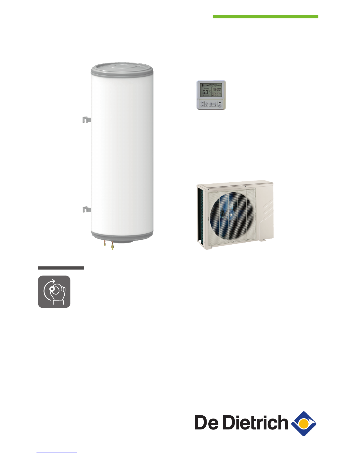
Thermodynamic water heater
KALIKO SPLIT
TWH Split WH 150 E
TWH Split WH 200 E
Serv. ref. SODU 2 M R1

Dear Customer,
Thank you very much for buying this appliance.
Please read through the manual carefully before using the product, and keep it in a safe place for later reference. In order to
ensure continued safe and efficient operation we recommend that the product is serviced regularly. Our service and customer
service organisation can assist with this.
We hope you enjoy years of problem-free operation with the product.

Contents
1 Safety . . . . . . . . . . . . . . . . . . . . . . . . . . . . . . . . . . . . . . . . . . . . . . . . . . . . . . . . . . . . . . . . . . . . . . . . . . . . . . . . . . . . . . . . . . . . 4
1.1 General safety instructions . . . . . . . . . . . . . . . . . . . . . . . . . . . . . . . . . . . . . . . . . . . . . . . . . . . . . . . . . . . . . . . . . . . . . . . 4
1.2 Recommendations . . . . . . . . . . . . . . . . . . . . . . . . . . . . . . . . . . . . . . . . . . . . . . . . . . . . . . . . . . . . . . . . . . . . . . . . . . . . . 5
1.3 R134a refrigerant . . . . . . . . . . . . . . . . . . . . . . . . . . . . . . . . . . . . . . . . . . . . . . . . . . . . . . . . . . . . . . . . . . . . . . . . . . . . . . 6
1.4 Liabilities . . . . . . . . . . . . . . . . . . . . . . . . . . . . . . . . . . . . . . . . . . . . . . . . . . . . . . . . . . . . . . . . . . . . . . . . . . . . . . . . . . . . . 8
1.4.1 Manufacturer's liability . . . . . . . . . . . . . . . . . . . . . . . . . . . . . . . . . . . . . . . . . . . . . . . . . . . . . . . . . . . . . . . . . . . 8
1.4.2 Installer's liability . . . . . . . . . . . . . . . . . . . . . . . . . . . . . . . . . . . . . . . . . . . . . . . . . . . . . . . . . . . . . . . . . . . . . . . 8
1.4.3 User's liability . . . . . . . . . . . . . . . . . . . . . . . . . . . . . . . . . . . . . . . . . . . . . . . . . . . . . . . . . . . . . . . . . . . . . . . . . .9
2 Operation . . . . . . . . . . . . . . . . . . . . . . . . . . . . . . . . . . . . . . . . . . . . . . . . . . . . . . . . . . . . . . . . . . . . . . . . . . . . . . . . . . . . . . . . .10
2.1 Energy-saving measures . . . . . . . . . . . . . . . . . . . . . . . . . . . . . . . . . . . . . . . . . . . . . . . . . . . . . . . . . . . . . . . . . . . . . . . 10
2.2 Description of the control panel keys . . . . . . . . . . . . . . . . . . . . . . . . . . . . . . . . . . . . . . . . . . . . . . . . . . . . . . . . . . . . . . 10
2.3 Description of the control panel display . . . . . . . . . . . . . . . . . . . . . . . . . . . . . . . . . . . . . . . . . . . . . . . . . . . . . . . . . . . . 10
2.4 Setting the time . . . . . . . . . . . . . . . . . . . . . . . . . . . . . . . . . . . . . . . . . . . . . . . . . . . . . . . . . . . . . . . . . . . . . . . . . . . . . . . 11
2.5 Activate / Deactivate the Holiday mode . . . . . . . . . . . . . . . . . . . . . . . . . . . . . . . . . . . . . . . . . . . . . . . . . . . . . . . . . . . . 11
2.6 Setting the domestic hot water temperature . . . . . . . . . . . . . . . . . . . . . . . . . . . . . . . . . . . . . . . . . . . . . . . . . . . . . . . . . 11
2.7 Programming the operating ranges . . . . . . . . . . . . . . . . . . . . . . . . . . . . . . . . . . . . . . . . . . . . . . . . . . . . . . . . . . . . . . . 11
2.8 Clearing the operating ranges . . . . . . . . . . . . . . . . . . . . . . . . . . . . . . . . . . . . . . . . . . . . . . . . . . . . . . . . . . . . . . . . . . . .12
2.9 Activate forced electrical back-up . . . . . . . . . . . . . . . . . . . . . . . . . . . . . . . . . . . . . . . . . . . . . . . . . . . . . . . . . . . . . . . . . 12
2.10 Displaying the measured values . . . . . . . . . . . . . . . . . . . . . . . . . . . . . . . . . . . . . . . . . . . . . . . . . . . . . . . . . . . . . . . . . . 12
3 Maintenance . . . . . . . . . . . . . . . . . . . . . . . . . . . . . . . . . . . . . . . . . . . . . . . . . . . . . . . . . . . . . . . . . . . . . . . . . . . . . . . . . . . . . . 14
3.1 General . . . . . . . . . . . . . . . . . . . . . . . . . . . . . . . . . . . . . . . . . . . . . . . . . . . . . . . . . . . . . . . . . . . . . . . . . . . . . . . . . . . . . 14
3.2 Maintenance operation intervals . . . . . . . . . . . . . . . . . . . . . . . . . . . . . . . . . . . . . . . . . . . . . . . . . . . . . . . . . . . . . . . . . . 14
3.3 Operate the safety valve or unit . . . . . . . . . . . . . . . . . . . . . . . . . . . . . . . . . . . . . . . . . . . . . . . . . . . . . . . . . . . . . . . . . . 14
4 Troubleshooting . . . . . . . . . . . . . . . . . . . . . . . . . . . . . . . . . . . . . . . . . . . . . . . . . . . . . . . . . . . . . . . . . . . . . . . . . . . . . . . . . . . .15
4.1 Resolving error codes . . . . . . . . . . . . . . . . . . . . . . . . . . . . . . . . . . . . . . . . . . . . . . . . . . . . . . . . . . . . . . . . . . . . . . . . . . 15
4.2 List of error codes . . . . . . . . . . . . . . . . . . . . . . . . . . . . . . . . . . . . . . . . . . . . . . . . . . . . . . . . . . . . . . . . . . . . . . . . . . . . . 15
4.3 Checks after a disconnection of the mains supply . . . . . . . . . . . . . . . . . . . . . . . . . . . . . . . . . . . . . . . . . . . . . . . . . . . . 15
5 Warranty . . . . . . . . . . . . . . . . . . . . . . . . . . . . . . . . . . . . . . . . . . . . . . . . . . . . . . . . . . . . . . . . . . . . . . . . . . . . . . . . . . . . . . . . . 17
5.1 General . . . . . . . . . . . . . . . . . . . . . . . . . . . . . . . . . . . . . . . . . . . . . . . . . . . . . . . . . . . . . . . . . . . . . . . . . . . . . . . . . . . . . 17
5.2 Terms of warranty . . . . . . . . . . . . . . . . . . . . . . . . . . . . . . . . . . . . . . . . . . . . . . . . . . . . . . . . . . . . . . . . . . . . . . . . . . . . . 17
6 Appendix . . . . . . . . . . . . . . . . . . . . . . . . . . . . . . . . . . . . . . . . . . . . . . . . . . . . . . . . . . . . . . . . . . . . . . . . . . . . . . . . . . . . . . . . . 18
6.1 Symbols used . . . . . . . . . . . . . . . . . . . . . . . . . . . . . . . . . . . . . . . . . . . . . . . . . . . . . . . . . . . . . . . . . . . . . . . . . . . . . . . . 18
6.1.1 Symbols used in the manual . . . . . . . . . . . . . . . . . . . . . . . . . . . . . . . . . . . . . . . . . . . . . . . . . . . . . . . . . . . . . 18
6.1.2 Symbols used on the appliance . . . . . . . . . . . . . . . . . . . . . . . . . . . . . . . . . . . . . . . . . . . . . . . . . . . . . . . . . . .18
6.2 Homologations . . . . . . . . . . . . . . . . . . . . . . . . . . . . . . . . . . . . . . . . . . . . . . . . . . . . . . . . . . . . . . . . . . . . . . . . . . . . . . . 18
6.2.1 NF certification . . . . . . . . . . . . . . . . . . . . . . . . . . . . . . . . . . . . . . . . . . . . . . . . . . . . . . . . . . . . . . . . . . . . . . . .18
6.2.2 Electrical Conformity / CE Marking . . . . . . . . . . . . . . . . . . . . . . . . . . . . . . . . . . . . . . . . . . . . . . . . . . . . . . . . 19
6.2.3 Directive 97/23/CE . . . . . . . . . . . . . . . . . . . . . . . . . . . . . . . . . . . . . . . . . . . . . . . . . . . . . . . . . . . . . . . . . . . . .19
6.2.4 Ecodesign Directive . . . . . . . . . . . . . . . . . . . . . . . . . . . . . . . . . . . . . . . . . . . . . . . . . . . . . . . . . . . . . . . . . . . 19
6.3 Disposal and Recycling . . . . . . . . . . . . . . . . . . . . . . . . . . . . . . . . . . . . . . . . . . . . . . . . . . . . . . . . . . . . . . . . . . . . . . . . .20
6.4 Package fiche - Water heaters . . . . . . . . . . . . . . . . . . . . . . . . . . . . . . . . . . . . . . . . . . . . . . . . . . . . . . . . . . . . . . . . . . . 20
6.5 Product fiche - Heat pump water heaters . . . . . . . . . . . . . . . . . . . . . . . . . . . . . . . . . . . . . . . . . . . . . . . . . . . . . . . . . . . 21
7 Maintenance form for the user . . . . . . . . . . . . . . . . . . . . . . . . . . . . . . . . . . . . . . . . . . . . . . . . . . . . . . . . . . . . . . . . . . . . . . . . 22
Contents
7647125 - v03 - 11092017 TWH Split WH 3
1 Safety
1.1 General safety instructions
Danger
This appliance can be used by children aged 8
years and above and by persons with reduced
physical, sensory or mental capabilities or lack of
experience and knowledge when they have been
given supervision or instruction concerning the
safe use of the device and understand the result
ing risks. Children must not be allowed to play
with the appliance. Cleaning and user mainte
nance must not be carried out by children without
supervision.
Danger
In the event of a refrigerant leakage:
1. Switch off the appliance.
2. Open the windows.
3. Do not use a naked flame, do not smoke, do
not operate electrical contacts.
4. Avoid contact with the refrigerant. Danger of
frost injuries.
5. Evacuate the property.
6. Contact a qualified professional.
Danger of electric shock
Before any work, switch off the mains supply to
the thermodynamic water heater.
Important
Only qualified professionals are permitted to in
stall the thermodynamic water heater, in accord
ance with prevailing local and national regula
tions.
Warning
Do not touch the refrigeration connection pipes
with your bare hands while the heat pump is run
ning. Danger of burn or frost injury.
1 Safety
4 TWH Split WH 7647125 - v03 - 11092017
Warning
A disconnection device must be fitted to the per
manent pipes in accordance with installation
rules.
Warning
If a power supply cable comes with the appliance
and it turns out to be damaged, it must be re
placed by the manufacturer, its after sales service
or persons with similar qualifications in order to
obviate any danger.
Caution
In order to prevent any danger owing to the unex
pected reset of the thermal circuit breaker, this
appliance must not be powered through an exter
nal switch, such as a timer, or be connected to a
circuit which is regularly switched on and off by
the electricity provider.
Warning
Respect the maximum water inlet pressure to en
sure correct operation of the appliance, referring
to the chapter Technical Specifications.
Warning
In order to limit the risk of being scalded, the in
stallation of a thermostatic mixing valve on the
domestic hot water flow pipes is obligatory.
Warning
Only qualified professionals are authorised to
work on the heat pump and the heating system.
Caution
The system must satisfy each point in the rules in
force in the country that govern works and inter
ventions in individual homes, blocks of flats or
other buildings.
1.2
Recommendations
Caution
To benefit from extended warranty cover, no
modifications must be made to the appliance.
Important
Keep this document close to the place where the
appliance is installed.
1 Safety
7647125 - v03 - 11092017 TWH Split WH 5
Important
Never remove or cover labels and data plates af
fixed to the appliances. Labels and data plates
must be legible throughout the entire lifetime of
the appliance.
Damaged or illegible instructions and warning
stickers must be replaced immediately.
Important
Keep the thermodynamic water heater accessible
at all times.
1.3
R134a refrigerant
Tab.1 Effects harmful to health
The vapours are heavier than air and may lead to asphyxia owing to reduced oxygen levels.
Liquefied gas Contact with the liquid may cause serious frost and eye injuries.
Product classification This product is not classified as a "hazardous preparation" accord
ing to European Union regulations.
Tab.2 Hazard identification
If the R134a refrigerant is mixed with air, it may cause pressure surges in the refrigeration
pipes and lead to an explosion and other hazards.
Tab.3 Composition of/Information on the R134a
Name Proportion Number CE Number CAS
GWP
(1)
1,1,1,2 - Tetrafluoroethane R134a 100% 212-377-0 811-97-2 1430
(1) Global Warming Potential
Tab.4 First aid
If inhaled
Evacuate the subject from the contaminated area and take
him into the open air
If feeling unwell: call a doctor.
In the event of contact with the
skin
Treat frost injuries like burns. Rinse with copious amounts
of tepid water, do not remove clothing (risk of adhesion to
the skin)
If skin burns appear, call a doctor immediately
In the event of contact with the
eyes
Rinse immediately with water, holding the eyelids well
apart (for at least 15 minutes)
Consult an ophthalmologist immediately
1 Safety
6 TWH Split WH 7647125 - v03 - 11092017
Tab.5 Fire prevention measures
Appropriate extinguishing agents All extinguishing agents can be used
Inappropriate extinguishing agents None to our knowledge. In the event of fire nearby, use
the appropriate extinguishing agents
Specific hazards Rise in pressure: in the presence of air, an inflamma
ble mixture may form under certain temperature and
pressure conditions
Toxic and corrosive vapours may be released by the
effect of the heat
Special intervention methods
Cool the volumes exposed to heat with water spray
Protection of the firemen Full self-contained breathing apparatus.
Complete body protection
Tab.6 In the event of accidental spillage
Individual precautions Avoid contact with the skin and eyes.
Do not intervene without appropriate protective equipment.
Do not inhale the vapour
Evacuate the hazardous area.
Stop the leakage.
Eradicate all sources of ignition.
Ventilate the spillage area mechanically (risk of asphyxia)
Cleaning / Decontamination
Allow residual product to evaporate
Tab.7 Personal protective equipment
Respiratory protec
tion
If ventilation is insufficient: AX-type cartridge mask
In confined spaces: self-contained breathing apparatus
Hand protection Protective gloves in leather or nitrile rubber
Eye protection Safety glasses with side protection
Skin protection Clothing made primarily of cotton
Industrial hygiene Do not drink, eat or smoke at the place of work
Tab.8 Handling
Technical measures
Ventilation
Precautions to be tak
en
No smoking.
Prevent the build-up of electrostatic charges.
Work in a well ventilated place
Tab.9 Considerations on disposal
Disposal must be done in compliance with prevailing local and national regulations.
1 Safety
7647125 - v03 - 11092017 TWH Split WH 7
Product waste Consult the manufacturer or the supplier for information on recovery or
recycling
Soiled packaging Reuse or recycle after decontamination. Destroy in authorised installa
tions
Tab.10 Regulation
Regulation (EU) No. 517/2014 of the European Parliament and of the Council of 16 April
2014 on fluorinated greenhouse gases and repealing Regulation (EC) No. 842/2006.
1.4
Liabilities
1.4.1
Manufacturer's liability
Our products are manufactured in compliance with the
requirements of the various Directives applicable. They
are therefore delivered with the
marking and any
documents necessary. In the interests of the quality of
our products, we strive constantly to improve them. We
therefore reserve the right to modify the specifications
given in this document.
Our liability as manufacturer may not be invoked in the
following cases:
Failure to abide by the instructions on installing the
appliance.
Failure to abide by the instructions on using the appli
ance.
Faulty or insufficient maintenance of the appliance.
1.4.2
Installer's liability
The installer is responsible for the installation and initial
commissioning of the appliance. The installer must ob
serve the following instructions:
Read and follow the instructions given in the manuals
provided with the appliance.
Install the appliance in compliance with prevailing leg
islation and standards.
Carry out initial commissioning and any checks neces
sary.
Explain the installation to the user.
If maintenance is necessary, warn the user of the obli
gation to check the appliance and keep it in good
working order.
Give all the instruction manuals to the user.
1 Safety
8 TWH Split WH 7647125 - v03 - 11092017

1.4.3
User's liability
To guarantee optimum operation of the system, you
must abide by the following instructions:
Read and follow the instructions given in the manuals
provided with the appliance.
Call on a qualified professional to carry out installation
and initial commissioning.
Get your installer to explain your installation to you.
Have the required inspections and maintenance car
ried out by a qualified installer.
Keep the instruction manuals in good condition close
to the appliance.
1 Safety
7647125 - v03 - 11092017 TWH Split WH 9

2 Operation
2.1 Energy-saving measures
Energy-saving advice.
1. Do not run hot and/or cold water pointlessly.
2. Install an energy-saving shower head, which can save up to 40 %
energy.
3. Take showers rather than baths. A bath consumes twice as much
water and energy.
2.2
Description of the control panel keys
1
Keys and :
Selection
Setting the values
2
On / off key for forced electrical back-up
3
Timer program access key
4
Confirm key
5
key:
Domestic hot water production
Holiday mode
6
Operating indicator light:
Indicator light on = Domestic hot water production active
Indicator light off = Holiday mode
2.3 Description of the control panel display
1 Hybrid mode operating
2 Heating temperature
Domestic hot water temperature
Error code detected
3 Error detected
4 Forced electrical back-up in operation
5 Compressor running
6 Time display
7 Timer program display
8 Off-peak rate optimisation mode in operation
Fig.1
MW-4000111-3
1
6
2
5
3 4
Electrical
Heating
Timer /
Clock
Enter
Opt ModeHybrid Mode
Fig.2
MW-4000112-3
Enter
Electrical
Heating
Timer /
Clock
Opt ModeHybrid Mode
2
3
4 5
6
7
8
1
2 Operation
10 TWH Split WH 7647125 - v03 - 11092017

2.4 Setting the time
1. Press the key to set the time.
The hours start flashing.
2. Set the hours and minutes by pressing the or keys.
3. Confirm the hours and minutes by pressing the key.
2.5 Activate / Deactivate the Holiday mode
For extended periods away, switch the thermodynamic water heater to
Holiday mode.
The Holiday mode should be used rather than shutting down the thermo
dynamic water heater to ensure the following functions operate:
Frost protection,
Saving control panel parameters.
1. Press the key on the control panel.
The indicator light goes out: Holiday mode is activated.
2. Press the key on the control panel.
The indicator light comes on: Holiday mode is deactivated.
2.6 Setting the domestic hot water temperature
The water temperature of the domestic hot water tank can be set accord
ing to the hot water usage.
1. Access the domestic hot water temperature settings by pressing the
key.
The domestic hot water temperature value will flash.
2. Set the domestic hot water temperature to the lowest possible set
ting to save energy without dropping below 55 °C by pressing the
or keys.
If there is insufficient hot water, increase the set point value.
3. Confirm by pressing the key.
2.7
Programming the operating ranges
The operating ranges of the thermodynamic water heater define the peri
ods when the water heater is to produce domestic hot water.
Two operating ranges are available: Timer 1 and Timer 2, they are set in
the same way, one after the other.
1. Select Timer 1 - On by pressing three times on the key.
2. Set the hours and minutes of the start time of the operating range by
pressing the or key.
3. Confirm the start of the operating range by pressing the key.
Fig.3
MW-4000168-3
Opt ModeHybrid Mode
Fig.4
MW-2000654-1
Electrical
Heating
Enter
Timer /
Clock
Opt ModeHybrid Mode
Fig.5
MW-4000177-4
Opt ModeHybrid Mode
Fig.6
MW-4000172-4
Opt ModeHybrid Mode
2 Operation
7647125 - v03 - 11092017 TWH Split WH 11

4. Set the hours and minutes of the end time of the operating range by
pressing the or key.
5. Confirm the end of the operating range by pressing the key.
6. Confirm the first operating range by pressing the key.
7. Select the second operating range by pressing the key, if neces
sary.
8. Repeat steps 2 to 6 to set the second operating range.
9. Confirm the second operating range by pressing the key.
2.8 Clearing the operating ranges
If one or two operating ranges are programmed, they can be cleared.
1. Clear the range or ranges by pressing the key for three seconds.
The two operating ranges will be cleared at once.
2. It is confirmed after a few seconds.
2.9
Activate forced electrical back-up
The forced electrical back-up mode enables domestic hot water to be pro
vided more quickly thanks to the simultaneous operation of the heat pump
and electrical back-up.
1. Activate forced electrical back-up by pressing the key.
The Electrical Heating icon flashes.
When the set temperature of the hot water is reached, the control
panel returns to Automatic mode.
2. It is confirmed after a few seconds.
2.10 Displaying the measured values
The system constantly measures different data, such as the water temper
ature or energy consumption. This data can be read on the control panel.
1. Press the and keys simultaneously.
Fig.7
MW-4000176-3
Opt ModeHybrid Mode
Fig.8
MW-4000178-4
Electrical
Heating
Timer /
Clock
Enter
Opt ModeHybrid Mode
2 Operation
12 TWH Split WH 7647125 - v03 - 11092017

2. Scroll through the measured values with the or keys.
Tab.11
Code Description Factory setting / Unit
Water temperature °C
Outside air temperature
(1)
°C
Evaporation temperature °C
Hysteresis for starting heating.
Can be set from 3 to 20°C.
5°C
Electric power consumption A
Differential live/neutral current A
Total energy consumption for the thermodynamic water heater kWh
Energy consumption of the heat pump from midnight Wh
Energy consumption of the immersion heater from midnight Wh
Total runtime for the thermodynamic water heater hours
Total duration of compressor operation hours
Total runtime for the immersion heater hours
Operating mode:
= : thermodynamic water heater off
= : heat pump on
= : electrical back-up on
Fan speed:
: fan off
: low speed
: high speed
First error code
Second error code
Third error code
Software version
(1) Negative temperatures are displayed as follows: –10 °C is displayed as –A, –11°C is displayed as –B, etc...
2 Operation
7647125 - v03 - 11092017 TWH Split WH 13

3 Maintenance
3.1 General
Caution
Do not neglect to service the domestic hot water tank or the heat
pump. Contact a qualified professional or take out a maintenance
contract for the obligatory annual servicing of the thermodynamic
water heater.
Failure to service the appliance voids the warranty.
The control and maintenance interventions for the appliance must be per
formed by a certified professional in accordance with prevailing statutory
texts and codes of practice.
Maintenance operations are important for the following reasons:
To guarantee optimum performance;
To extend the life of the equipment;
To provide an installation which offers the customer optimum comfort
over time.
Remove the thermodynamic water heater casing only to perform mainte
nance and repair work.
3.2 Maintenance operation intervals
The maintenance form is available in the appendix.
Tab.12 General maintenance
Operation Periodicity Installer User
Operate the safety valve or unit once a month X
Tab.13 Outdoor unit maintenance
Maintenance operations on the outdoor unit Periodicity Installer User
Clean the casing using a damp soft cloth once a year X
Check the cleanliness of the outdoor unit fan once a year X
Tab.14 Maintenance of the domestic hot water tank
Operations Periodicity Installer User
Clean the casing using a damp soft cloth once a year X
Descaling the domestic hot water tank after the first year of use
and then every two years
X
Checking the magnesium anode after the first year of use
and then every two years
X
3.3
Operate the safety valve or unit
To take the proper precautions against possible pressure surges which
would damage the domestic hot water tank, ensure the safety valve or unit
functions correctly. Failure to follow this maintenance requirement may
lead to damage of the domestic hot water tank and void its warranty.
1. Operate the safety valve or unit at least once a month.
2. Have the safety valve or unit replaced if necessary by an approved
installer.
3 Maintenance
14 TWH Split WH 7647125 - v03 - 11092017

4 Troubleshooting
4.1 Resolving error codes
If an error occurs, the control panel will display a key and a code The code
is important for the correct and rapid diagnosis of the type of malfunction
and for any technical assistance that may be needed.
1. Make a note of the code displayed.
2. Switch off the appliance.
3. Switch the appliance back on.
The appliance starts up again autonomously when the reason for
the disruption has been cleared.
4. If the error code is displayed again, correct the problem by following
the instructions in the table below.
4.2
List of error codes
If one of the following error codes is displayed, contact your authorised
maintenance technician.
Tab.15 Ex-type error codes
Code Description
Communication error between the outdoor unit and the control panel
Water temperature sensor T5L error
Evaporation temperature sensor T3 error
Air temperature sensor T4 error
Air suction temperature sensor Th error
Air discharge temperature sensor Tp error
Tab.16 Px type error codes
Code Description
High pressure error
Electrical overconsumption error on the compressor
Discharge temperature error: too high
Air temperature information outside the operating limits
Consumption error on the electrical back-up
The heat pump continues to operate but without electrical back-up
Error on the main controller
Frost protection running
4.3
Checks after a disconnection of the mains supply
1. Check that the thermodynamic water heater is running (green LED
on). Otherwise, press the MODE key.
2. Check the time setting on the control panel.
3. Check the programming of the operating ranges.
Fig.9
MW-4000188-3
Electrical
Heating
Enter
Timer /
Clock
Opt ModeHybrid Mode
4 Troubleshooting
7647125 - v03 - 11092017 TWH Split WH 15

For more information, see
Activate / Deactivate the Holiday mode, page 11
Setting the time, page 11
Programming the operating ranges, page 11
4 Troubleshooting
16 TWH Split WH 7647125 - v03 - 11092017

5 Warranty
5.1 General
We would like to thank you for buying one of our appliances and for your
trust in our product.
In order to ensure continued safe and efficient operation, we recommend
that the product is regularly inspected and maintained.
Your installer and our service department can assist with this.
5.2
Terms of warranty
The following provisions do not affect the application, in favour of the buy
er, of the legal provisions with regard to hidden defects that are applicable
in the buyer's country.
This appliance comes with a warranty that covers all manufacturing faults;
the warranty period will commence on the date of purchase stated on the
installer's invoice.
The warranty period is stated in our price list.
As a manufacturer, we can by no means be held liable if the appliance is
used incorrectly, is poorly maintained or not maintained at all, or is not in
stalled correctly (it is your responsibility to ensure that installation is carried
out by a qualified installer).
In particular, we cannot be held liable for material damage, intangible los
ses or physical injury resulting from an installation that does not comply
with:
Legal or regulatory requirements or provisions laid down by the local au
thorities.
National or local regulations and special provisions relating to the instal
lation.
Our manuals and installation instructions, in particular in terms of regular
maintenance of the appliances.
Our warranty is limited to the replacement or repair of the parts found to
be defective by our technical services team, excluding labour, transfer and
transport costs.
Our warranty does not cover replacement or repair costs for parts that may
become defective due to normal wear, incorrect usage, the intervention of
unqualified third parties, inadequate or insufficient supervision or mainte
nance, a mains supply that is not appropriate or the use of unsuitable or
poor quality fuel.
Smaller parts, such as motors, pumps, electrical valves etc., are guaran
teed only if these parts have never been dismantled.
The rights established in European Directive 99/44/EEC, implemented by
legal decree No. 24 of 2 February 2002 and published in Official Journal
No. 57 of 8 March 2002, remain in force.
5 Warranty
7647125 - v03 - 11092017 TWH Split WH 17

6 Appendix
6.1 Symbols used
6.1.1 Symbols used in the manual
This manual uses various danger levels to draw attention to special in
structions. We do this to improve user safety, to prevent problems and to
guarantee correct operation of the appliance.
Danger
Risk of dangerous situations that may result in serious personal
injury.
Danger of electric shock
Risk of electric shock.
Warning
Risk of dangerous situations that may result in minor personal in
jury.
Caution
Risk of material damage.
Important
Please note: important information.
See
Reference to other manuals or pages in this manual.
6.1.2 Symbols used on the appliance
1 Alternating current
2 Protective earthing
3 Before installing and commissioning the appliance, carefully read
the instruction manuals provided.
4 Dispose of used products through an appropriate recovery and re
cycling structure.
5 Caution: danger of electric shock, live parts. Disconnect the mains
power prior to carrying out any work.
6 Electrical back-up
7 CE Marking: equipment conforming to European legislation
8 NF Marking: equipment that respects French safety and perform
ance criteria
9 Protection rating.
6.2
Homologations
6.2.1 NF certification
Specifications LCIE 103–15/B (July 2011) for NF Electricity Performance
Marking
This product complies with the requirements of the following NF Electric
ity Standards:
EN 60335-1:2012 + A11:2014
EN 60335-2-21:2003 + A1:2005 + A2:2008
EN 60335-2-40:2003 + A11:2004 + A12:2005 + A1:2006 + A2:2009 +
A13:2012
Fig.10
MW-2000407-2
1
2
3
4
5
6
7
8
9
IP24
6 Appendix
18 TWH Split WH 7647125 - v03 - 11092017

EN 62233:2008
EN 16147:2011
EN 55014-1:2006+A1:2009+A2:2011
EN 55014-2:2015
EN 61000-3-2:2014
EN 61000-3-3:2013
6.2.2
Electrical Conformity / CE Marking
This product complies with the requirements of the following European Di
rectives and Standards:
Low Voltage Directive 2014/35/EU
Generic standard: EN 60335-1
Relevant standards: EN 60335-2-21, EN 60335-2-40
Electromagnetic Compatibility Directive 2014/30/EU
Generic standards: EN 61000-6-3, EN 61000-6-1
Relevant Standard: EN 55014
6.2.3
Directive 97/23/CE
This product conforms to the requirements of European Directive
97/23/EC, article 3, paragraph 3, on pressure equipment.
6.2.4 Ecodesign Directive
This product conforms to the requirements of European Directive
2009/125/EC on the ecodesign of energy-related products.
6 Appendix
7647125 - v03 - 11092017 TWH Split WH 19

6.3 Disposal and Recycling
Warning
The thermodynamic water heater must be dismantled and scrap
ped by a qualified professional in accordance with prevailing local
and national regulations.
6.4 Package fiche - Water heaters
Fig.12 Package fiche for water heaters indicating the water heating energy efficiency of the package
AD-3000762-01
%
1
‘I’
2
%(1.1 x ‘I’ - 10%) x ‘II’ - - ‘I’ = +
‘III’
<28%
XXL
XL
L
M
G F E D C B A A
+
A
++
A
+++
3
%
%+ 0.4 x =
23
%- 0.2 x =
23
The energy effi ciency of the package of products provided for in this fi che may not correspond to its actual energy effi ciency once installed
in a building, as this effi ciency is infl uenced by further factors such as heat loss in the distribution system and the dimensioning of the
products in relation to building size and characteristics.
Water heating energy effi ciency class of package under average climate
Water heating energy effi ciency of package under average climate
Auxiliary electricity
Solar contribution
Water heating energy effi ciency of water heater
from fi che of solar device
Colder:
Warmer:
Water heating energy effi ciency under colder and warmer climate conditions
Declared load profi le:
I The value of the water heating energy efficiency expressed in %.
II The value of the mathematical expression (220 · Q
ref
)/Q
nonsol
,
where Q
ref
is taken from Regulation EU 812/2013, Annex VII Table
3 and Q
nonsol
from the product fiche of the solar device for the de
clared load profile M, L, XL or XXL of the water heater.
Fig.11 Recycling
MW-3000179-03
6 Appendix
20 TWH Split WH 7647125 - v03 - 11092017

III The value of the mathematical expression (Q
aux
· 2,5)/(220 · Q
ref
),
expressed in %, where Q
aux
is taken from the product fiche of the
solar device and Q
ref
from Regulation EU 812/2013, Annex VII Ta
ble 3 for the declared load profile M, L, XL or XXL.
6.5 Product fiche - Heat pump water heaters
Tab.17 Product fiche for heat pump water heaters
Brand name - Product name Unit TWH Split WH
150 E
TWH Split WH
200 E
Declared load profile – LL LL
Water heating energy efficiency class under average climate conditions –
A
A
Water heating energy efficiency under average climate conditions % L140.00 L125.00
Annual energy consumption
kWh
(1)
GJ
(2)
L733 L818
Other load profiles for which the water heater is suitable to use and the
corresponding water heating energy efficiency and annual electricity con
sumption
(3)
- – –
Thermostat temperature setting °C 55.00 55.00
Sound power level LWA indoors
(1)
dB 15 15
Ability to function during off-peak hours
(1)
– No No
Enabled smart control settings
(4)
– No No
Water heating energy efficiency, under colder - warmer climate conditions % 90.00 - 154.00 85.00 - 144.00
Annual energy consumption, under colder - warmer climate conditions
kWh
(1)
GJ
(1)
1141 - 661 1210 - 710
Sound power level LWA outdoors dB 59 59
(1) Electricity
(2) Fuel
(3) If applicable.
(4) If smart control settings value is "1", the water heating energy efficiency and annual electricity and fuel consumption only relate to ena
bled smart control settings
See
For specific precautions concerning assembling, installing and
maintaining: Safety, page 4
6 Appendix
7647125 - v03 - 11092017 TWH Split WH 21

7 Maintenance form for the user
Tab.18 Maintenance carried out by the user
No. Operation Periodicity
1 Operate the safety valve or unit once a month
2 Clean the outdoor unit casing using a damp soft cloth once a year
3 Clean the domestic hot water tank casing using a damp soft cloth once a year
Tab.19 Maintenance carried out by user no. 1: Date __________
No. Remarks By Signature
1
2
3
Tab.20 Maintenance carried out by user no. 2: Date __________
No. Remarks By Signature
1
2
3
Tab.21 Maintenance carried out by user no. 3: Date __________
No. Remarks By Signature
1
2
3
Tab.22 Maintenance carried out by user no. 4: Date __________
No. Remarks By Signature
1
2
3
Tab.23 Maintenance carried out by user no. 5: Date __________
No. Remarks By Signature
1
2
3
7 Maintenance form for the user
22 TWH Split WH 7647125 - v03 - 11092017

© Copyright
All technical and technological information contained in these technical instructions, as well as any drawings and technical de
scriptions supplied, remain our property and shall not be multiplied without our prior consent in writing. Subject to alterations.

DE DIETRICH THERMIQUE
57, rue de la Gare F- 67580 MERTZWILLER - BP 30
MW-8000005-12
7647125 - v03 - 11092017
7647125-001-03
 Loading...