

Page 1
DIETRISOL
Solar domestic hot water tanks
TRIO DT 250 - TRIO DT 350
EN
M000854
User Guide
300028005-001-03
Page 2

Contents
1 Introduction . . . . . . . . . . . . . . . . . . . . . . . . . . . . . . . . . . . . . . . . . . . . . . . . . . . . . . . . . . . . . . . . . . . . . . . . . . . . .3
1.1 Symbols and abbreviations . . . . . . . . . . . . . . . . . . . . . . . . . . . . . . . . . . . . . . . . . . . . . . . . . . . . . . . . . . . . . . . . . . . . . . . . . . . . . . . .3
1.2 General. . . . . . . . . . . . . . . . . . . . . . . . . . . . . . . . . . . . . . . . . . . . . . . . . . . . . . . . . . . . . . . . . . . . . . . . . . . . . . . . . . . . . . . . . . . . . . . .3
1.2.1 Manufacturer's liability . . . . . . . . . . . . . . . . . . . . . . . . . . . . . . . . . . . . . . . . . . . . . . . . . . . . . . . . . . . . . . . . . . . . . . . . . . . . . . 3
1.2.2 Installer's liability . . . . . . . . . . . . . . . . . . . . . . . . . . . . . . . . . . . . . . . . . . . . . . . . . . . . . . . . . . . . . . . . . . . . . . . . . . . . . . . . . .3
1.2.3 User's liability . . . . . . . . . . . . . . . . . . . . . . . . . . . . . . . . . . . . . . . . . . . . . . . . . . . . . . . . . . . . . . . . . . . . . . . . . . . . . . . . . . . . .3
1.2.4 Compliance of design and manufacture. . . . . . . . . . . . . . . . . . . . . . . . . . . . . . . . . . . . . . . . . . . . . . . . . . . . . . . . . . . . . . . . .3
1.2.5 Electrical compliance / Marking 1 . . . . . . . . . . . . . . . . . . . . . . . . . . . . . . . . . . . . . . . . . . . . . . . . . . . . . . . . . . . . . . . . . . . .4
2 Safety instructions and recommendations. . . . . . . . . . . . . . . . . . . . . . . . . . . . . . . . . . . . . . . . . . . . . . . . . . . .4
2.1 Safety instructions . . . . . . . . . . . . . . . . . . . . . . . . . . . . . . . . . . . . . . . . . . . . . . . . . . . . . . . . . . . . . . . . . . . . . . . . . . . . . . . . . . . . . . .4
2.2 Recommendations . . . . . . . . . . . . . . . . . . . . . . . . . . . . . . . . . . . . . . . . . . . . . . . . . . . . . . . . . . . . . . . . . . . . . . . . . . . . . . . . . . . . . . .4
3 Technical description . . . . . . . . . . . . . . . . . . . . . . . . . . . . . . . . . . . . . . . . . . . . . . . . . . . . . . . . . . . . . . . . . . . . .5
3.1 Technical specifications . . . . . . . . . . . . . . . . . . . . . . . . . . . . . . . . . . . . . . . . . . . . . . . . . . . . . . . . . . . . . . . . . . . . . . . . . . . . . . . . . . .5
3.2 Main parts. . . . . . . . . . . . . . . . . . . . . . . . . . . . . . . . . . . . . . . . . . . . . . . . . . . . . . . . . . . . . . . . . . . . . . . . . . . . . . . . . . . . . . . . . . . . . .8
4 Setting the DHW calorifier outlet temperature . . . . . . . . . . . . . . . . . . . . . . . . . . . . . . . . . . . . . . . . . . . . . . . . .9
4.1 Programming and setting the electrical back-up. . . . . . . . . . . . . . . . . . . . . . . . . . . . . . . . . . . . . . . . . . . . . . . . . . . . . . . . . . . . . . . . .9
4.2 Setting the thermostatic mixing valve . . . . . . . . . . . . . . . . . . . . . . . . . . . . . . . . . . . . . . . . . . . . . . . . . . . . . . . . . . . . . . . . . . . . . . . . .9
5 Diemasol B solar regulator. . . . . . . . . . . . . . . . . . . . . . . . . . . . . . . . . . . . . . . . . . . . . . . . . . . . . . . . . . . . . . . .10
5.1 General description of how the unit operates . . . . . . . . . . . . . . . . . . . . . . . . . . . . . . . . . . . . . . . . . . . . . . . . . . . . . . . . . . . . . . . . . .10
5.2 Start-up. . . . . . . . . . . . . . . . . . . . . . . . . . . . . . . . . . . . . . . . . . . . . . . . . . . . . . . . . . . . . . . . . . . . . . . . . . . . . . . . . . . . . . . . . . . . . . .10
5.3 Adjustment keys . . . . . . . . . . . . . . . . . . . . . . . . . . . . . . . . . . . . . . . . . . . . . . . . . . . . . . . . . . . . . . . . . . . . . . . . . . . . . . . . . . . . . . . .11
5.4 LED message code . . . . . . . . . . . . . . . . . . . . . . . . . . . . . . . . . . . . . . . . . . . . . . . . . . . . . . . . . . . . . . . . . . . . . . . . . . . . . . . . . . . . .12
5.5 Measured values and adjustment parameters . . . . . . . . . . . . . . . . . . . . . . . . . . . . . . . . . . . . . . . . . . . . . . . . . . . . . . . . . . . . . . . . .12
6 Checking and maintenance . . . . . . . . . . . . . . . . . . . . . . . . . . . . . . . . . . . . . . . . . . . . . . . . . . . . . . . . . . . . . . .17
6.1 Solar installation . . . . . . . . . . . . . . . . . . . . . . . . . . . . . . . . . . . . . . . . . . . . . . . . . . . . . . . . . . . . . . . . . . . . . . . . . . . . . . . . . . . . . . . .17
6.2 Tank . . . . . . . . . . . . . . . . . . . . . . . . . . . . . . . . . . . . . . . . . . . . . . . . . . . . . . . . . . . . . . . . . . . . . . . . . . . . . . . . . . . . . . . . . . . . . . . . .17
6.2.1 Magnesium anodes . . . . . . . . . . . . . . . . . . . . . . . . . . . . . . . . . . . . . . . . . . . . . . . . . . . . . . . . . . . . . . . . . . . . . . . . . . . . . . .17
6.2.2 Safety valve or safety unit . . . . . . . . . . . . . . . . . . . . . . . . . . . . . . . . . . . . . . . . . . . . . . . . . . . . . . . . . . . . . . . . . . . . . . . . . .17
6.2.3 Descaling . . . . . . . . . . . . . . . . . . . . . . . . . . . . . . . . . . . . . . . . . . . . . . . . . . . . . . . . . . . . . . . . . . . . . . . . . . . . . . . . . . . . . . .17
6.2.4 Casing . . . . . . . . . . . . . . . . . . . . . . . . . . . . . . . . . . . . . . . . . . . . . . . . . . . . . . . . . . . . . . . . . . . . . . . . . . . . . . . . . . . . . . . . .17
6.2.5 Vent device . . . . . . . . . . . . . . . . . . . . . . . . . . . . . . . . . . . . . . . . . . . . . . . . . . . . . . . . . . . . . . . . . . . . . . . . . . . . . . . . . . . . .17
6.3 Solar circuit. . . . . . . . . . . . . . . . . . . . . . . . . . . . . . . . . . . . . . . . . . . . . . . . . . . . . . . . . . . . . . . . . . . . . . . . . . . . . . . . . . . . . . . . . . . .17
Warranty certificate . . . . . . . . . . . . . . . . . . . . . . . . . . . . . . . . . . . . . . . . . . . . . . . . . . . . . . . . . . . . . . . . . . . . . .19
2
TRIO DT 250 - TRIO DT 350 17/10/12 - 300028005-001-03
Page 3

1Introduction
1.1 Symbols and abbreviations
In these instructions, various markings and pictograms are used to
draw your attention to particular information. In so doing, De Dietrich
Thermique S.A.S wishes to safeguard the user's safety, obviate
hazards and guarantee correct operation of the appliance.
Danger
Risk of a dangerous situation causing serious physical
injury.
Warning
Risk of a dangerous situation causing slight physical
injury.
1.2 General
Congratulations on choosing a De Dietrich product, a product of
quality. We strongly recommend that you read the following
instructions in order to guarantee the optimal operation of your
appliance. We are sure that you will not be disappointed and that it
will satisfy all of your expectations.
1.2.1 Manufacturer's liability
Our products are manufactured in compliance with the requirements
of the various applicable European Directives. They are therefore
delivered with 1 marking and all relevant documentation.
In the interest of customers, we are continuously endeavouring to
make improvements in product quality. All the specifications stated in
this document are therefore subject to change without notice.
Caution
Risk of material damage.
Specific information.
Reference
Z
Refer to another manual or other pages in this instruction
manual.
` DHW: Domestic hot water.
Our liability as the manufacturer may not be invoked in the following
cases:
` Failure to abide by the instructions on using the appliance.
` Faulty or insufficient maintenance of the appliance.
` Failure to abide by the instructions on installing the appliance.
1.2.2 Installer's liability
The installer is responsible for the installation and inital start up of the
appliance. The installer must respect the following instructions:
` Read and follow the instructions given in the manuals provided
with the appliance.
` Carry out installation in compliance with the prevailing
legislation and standards.
1.2.3 User's liability
To ensure the optimum operation of your appliance, we strongly
recommend that you abide by the following instructions:
` Read and follow the instructions given in the manuals provided
with the appliance.
` Call on qualified professionals to carry out installation and initial
start up.
1.2.4 Compliance of design and manufacture
This product conforms to the requirements of european directive 97 /
23 / EC, article 3, paragraph 3, on pressure equipment.
` Perform the initial start up and carry out any checks necessary.
` Explain the installation to the user.
` If a maintenance is necessary, warn the user of the obligation
to check the appliance and maintain it in good working order.
` Give all the instruction manuals to the user.
` Get your installer to explain your installation to you.
` Have the required checks and services done.
` Keep the instruction manuals in good condition close to the
appliance.
17/10/12 - 300028005-001-03 TRIO DT 250 - TRIO DT 350
3
Page 4

1.2.5 Electrical compliance / Marking
1
This product complies to the requirements to the european directives
and following standards:
• 2006/95/EC Low Voltage Directive
Reference Standard: EN 60.335.1.
• 2004/108/EC Electromagnetic Compatibility Directive
Reference Standards: EN 50.081.1 / EN 50.082.1 / EN 55.014.
2 Safety instructions and recommendations
2.1 Safety instructions
Any work on the installation must be done by a qualified
professional in compliance with the codes of practice and
according to the instructions provided.
2.2 Recommendations
Have the installation regularly serviced to guarantee that it operates
correctly over time.
It is essential to check the magnesium anode in the DHW tank and
the installation and heat transporting fluid pressure every two years.
Never cut the power to the solar control system, even
during extended absences. The control system protects
the installation against overheating in summer when it is
running.
During extended absences, we recommend lowering the set
point temperature in the solar DHW calorifier to 50°C. When the
user is present, the set point must be set to 60°C.
Never drain the installation. Do not replace or add water or
solar fluid to the installation. These actions must be carried
out by a qualified technician.
Do not modify the control system parameters unless fully
conversant with them.
4
TRIO DT 250 - TRIO DT 350 17/10/12 - 300028005-001-03
Page 5
3 Technical description
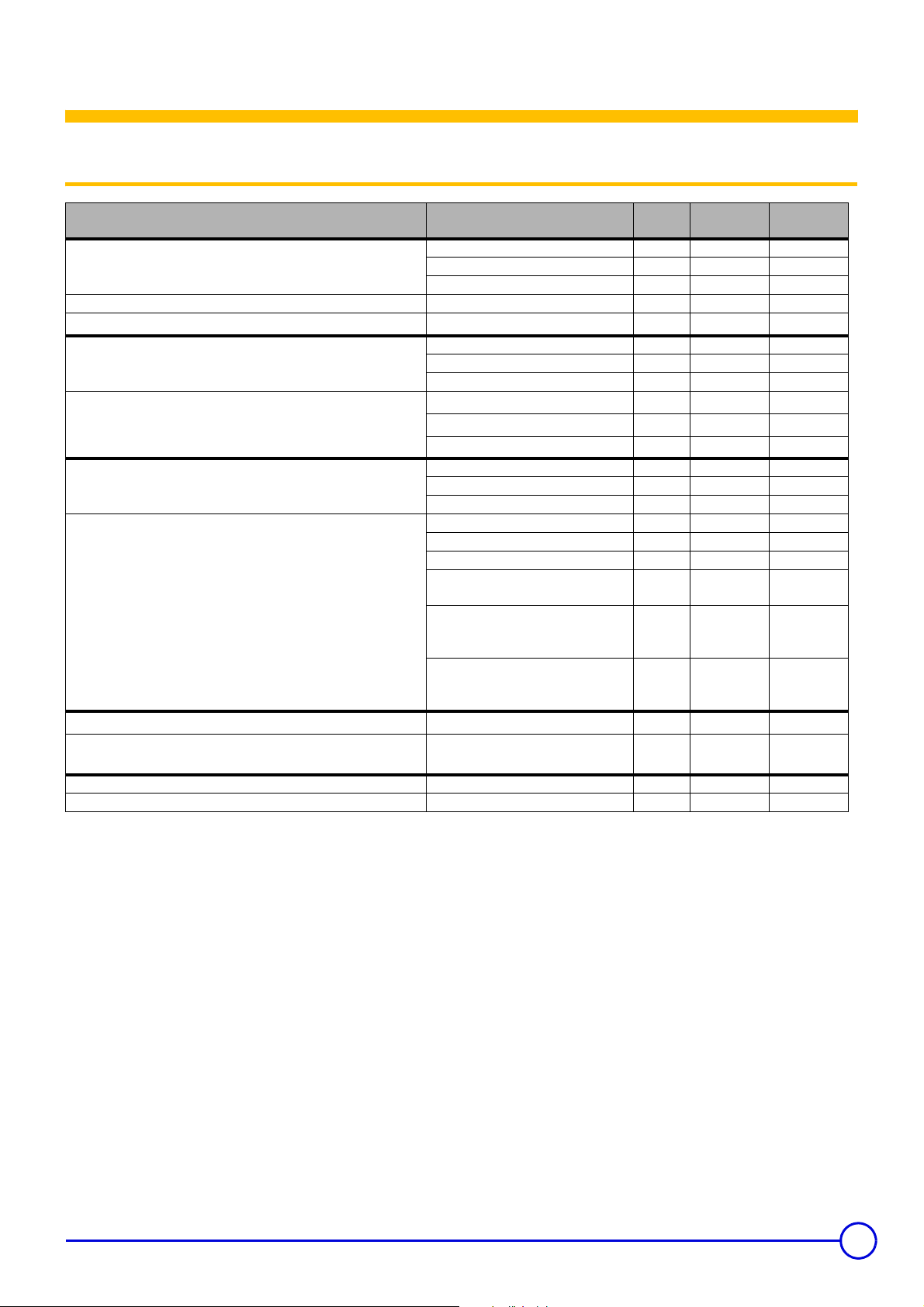
3.1 Technical specifications
DIETRISOL
TRIO DT 250
Solar exchangers °C 120 120
Maximum operating temperature
Maximum operating pressure bar 7 10
Maximum operating pressure in accordance with W/TPW
Water content
Surface area
Operation with boiler back-up
Operation with electrical back-up
Continuous output
Flow rate for 10 minutes where
(4)
Maintenance consumption kWh/24h - 2.7
Cooling constant Cr Wh/lKj 0.22 0.19
(1) Swiss Directives
(2) Domestic cold water input at 10°C - Primary inlet temperature at 80 °C
Values measured with a wall-mounted boiler
(3) Domestic hot water temperature: 45 °C
(4) Domestic hot water temperature: 40 °C
(5) Domestic cold water inlet 15 °C
(6) Values measured only on the back-up volume
Domestic hot water load setting: 60 °C
∆T = 35 K (2) (3)
∆T = 30 K (on make-up volume) (2)
(1)
Boiler heat exchanger °C 90 90
tank °C 90 90
bar 6 6
Solar exchangers litres 9 8.1
Boiler heat exchanger litres 4.3 4.9
tank litres 250 350
Upper solar heat exchanger
Lower solar heat exchanger
Boiler heat exchanger
Top up volume litres 105 127
Solar volume litres 145 223
Power exchanged (2) (3) kW 21 23
Top up volume litres 130 160
Solar volume litres 120 190
Output of the electrical back-up kW 2.4 3
Back-up volume heating time (from 15
to 60°C)
Vecs 40 (5) (6)
Domestic hot water storage
temperature: 55 °C
Vecs40 (5) (6)
Domestic hot water storage
temperature: 60 °C
2
m
2
m
2
m
h 2h50 2h50
litres 355 420
litres 385 450
l/h 515 565
l/10 mm 190 230
0.48 0.48
0.86 0.96
0.64 0.72
DIETRISOL
TRIO DT 350
17/10/12 - 300028005-001-03 TRIO DT 250 - TRIO DT 350
5
Page 6
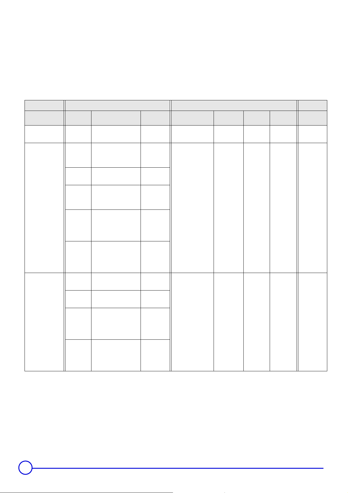
Composition of the NF CESI DIETRISOL TRIO solar systems packages (for France only)
Check the composition of the CESI solar system, which complies
with the requirements of the NF CESI mark, using the table below.
The references and packages listed must be shown on the invoice for
the system sold by the installer.
A system is complete and functional according to the NF CESI mark
if all system references appear on the invoice.
The system is composed of the following elements:
• A collector field with 1 or 2 solar collectors.
• A solar domestic hot water tank to which a solar station
incorporating a heating pump, an expansion vessel and a
Diemasol A control system is to be mounted.
• The solar fluid that protects the installation from frost and
corrosion.
The system is delivered to the installer in two units: a roof pack
containing the collectors, their mounting system and the hydraulic
connections on the one hand, and a cellar pack containing the
calorifier, the system components and the solar fluid on the other
hand.
CESI System Array of collectors Domestic hot water production Solar fluid
DIETRISOL TRIO
250-3
DIETRISOL TRIO
D 250-4
Number of
panels
1On roof
2
2
2
2
Type of mounting
On roof
(mechanical tiles -
Universal hook)
On roof
(Slates)
On roof
(mechanical tiles - On
rafter)
Roof-integral
Installation
(> 20°)
(mechanical tiles)
package /
Reference
ER 234
100019328
ER 432
100019695
ER 433
100019696
ER 434
100019697
ER 442
100019705
DHW calorifier type
DT 250
DT 250
package /
Reference
EC 340
100007796
EC 340
100007796
Volume
(litres)
250 Mixed
250 Mixed
Back-up
type
package /
Reference
89807792
89807792
EG 100
EG 100
DIETRISOL TRIO
250-5
2
2
2
2
2
(Delivered vertically)
(Delivered horizontally)
(Delivered vertically)
(Delivered horizontally)
Roof-integral
Installation
(> 20°)
(Slates / Flat tile)
On roof
On roof
Roof-integral
Installation
(> 20°)
Roof-integral
Installation
(> 20°)
ER 446
100019709
EC 521
100007869
EC 580
100009302
EC 531
100007879
EC 586
100009308
DT 250
EC 340
100007796
250 Mixed
EG 100
89807792
6
TRIO DT 250 - TRIO DT 350 17/10/12 - 300028005-001-03
Page 7
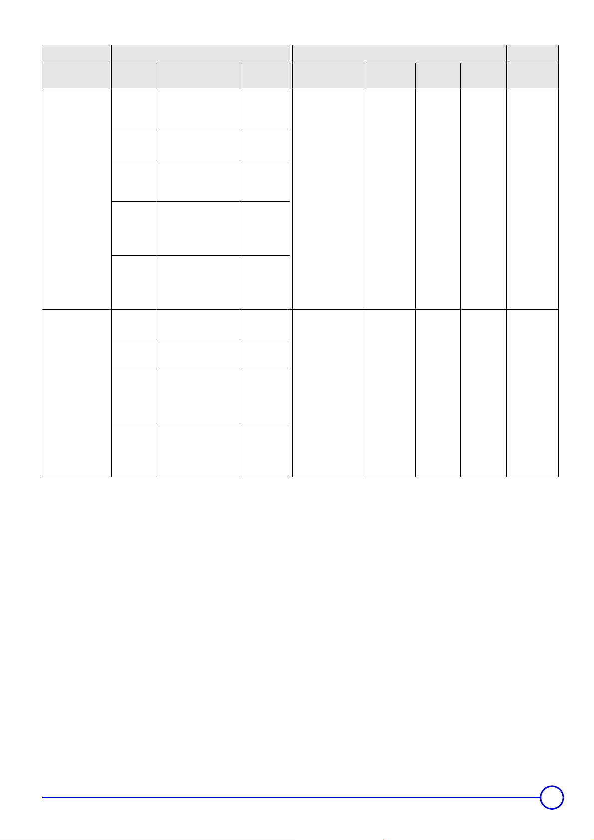
CESI System Array of collectors Domestic hot water production Solar fluid
Number of
panels
2
Type of mounting
On roof
(mechanical tiles -
Universal hook)
package /
Reference
ER 432
100019695
DHW calorifier type
package /
Reference
Volume
(litres)
Back-up
type
package /
Reference
DIETRISOL TRIO
D 350-4
DIETRISOL TRIO
350-5
2
2
2
2
2
2
2
(mechanical tiles - On
(Delivered vertically)
(Delivered horizontally)
(Delivered vertically)
On roof
(Slates)
On roof
rafter)
Roof-integral
Installation
(> 20°)
(mechanical tiles)
Roof-integral
Installation
(> 20°)
(Slates / Flat tile)
On roof
On roof
Roof-integral
Installation
(> 20°)
ER 433
100019696
ER 434
100019697
ER 442
100019705
ER 446
100019709
EC 521
100007869
EC 580
100009302
EC 531
100007879
DT 350
DT 350
EC 339
100007795
EC 339
100007795
350 Mixed
350 Mixed
EG 100
89807792
EG 100
89807792
2
See chapter: NF CESI data sheet.
Z
Roof-integral
Installation
(> 20°)
(Delivered horizontally)
EC 586
100009308
17/10/12 - 300028005-001-03 TRIO DT 250 - TRIO DT 350
7
Page 8
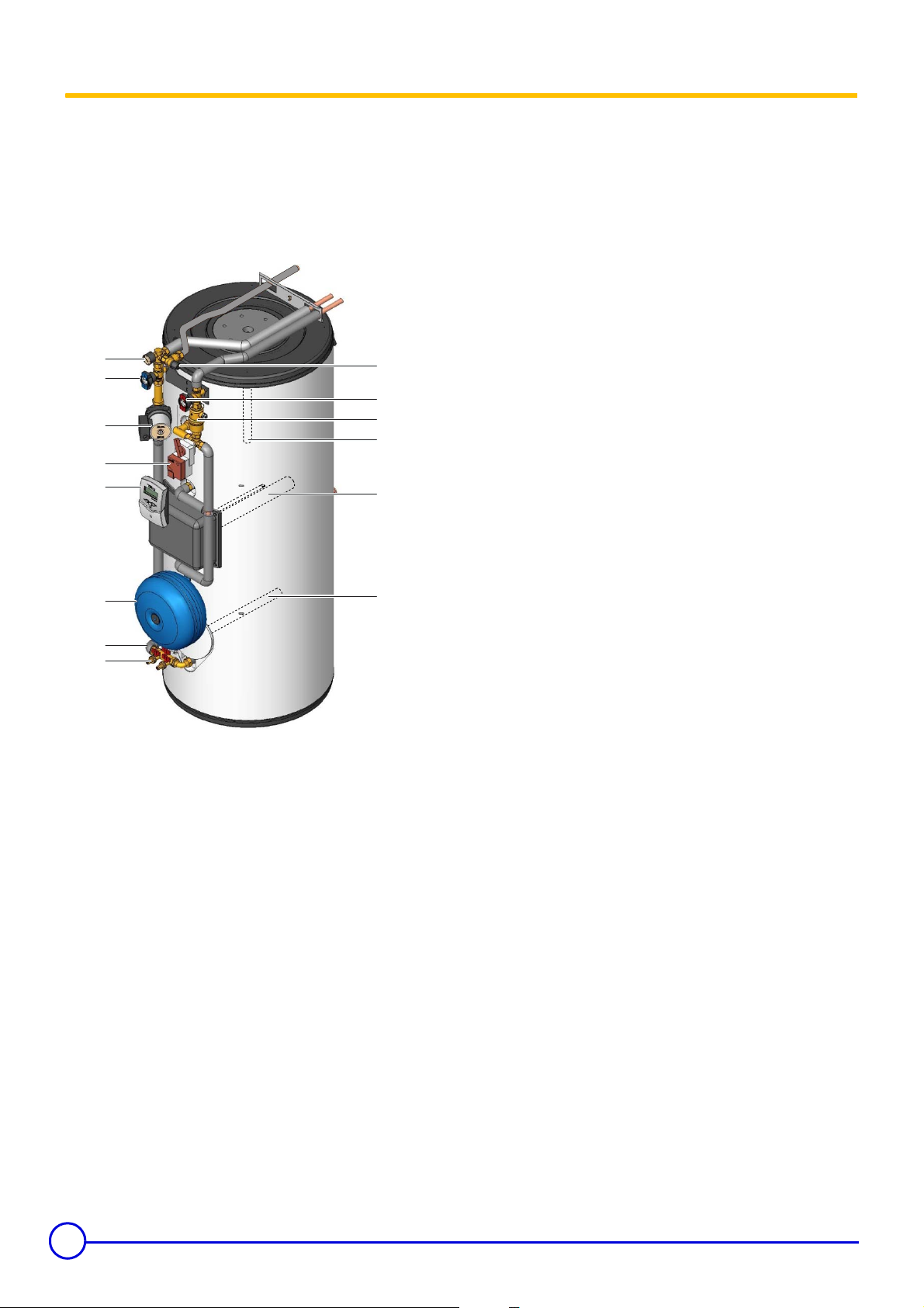
3.2 Main parts
Dietrisol TRIO DT ... is a high performance solar DHW tank/calorifier
designed to be connected to Dietrisol NEO or POWER solar
collectors and an De Dietrich central heating boiler.
It is designed in such a way as to be able to cope with a solar collector
surface area of up to 4.5 m
conditions set out in the chapter "Hydraulic Connection Primary Solar
Circuit".
1
2
(DT 250) and 6.5 m2 (DT 350) under the
2
3
4
5
6
12
7
8
13
tank
The high quality steel tank is lined with food standard quality
vitrified enamel, which protects it from corrosion and preserves
all the qualities of the domestic water.
The Dietrisol TRIO DT ... tank is fitted with 2 heat exchangers
per zone for solar heating and one heat exchanger for
supplementary heating by means of a fuel oil or gas boiler.
Protection against corrosion
The tank is also protected from corrosion by two magnesium
anodes which must be inspected every 2 years and replaced if
necessary.
Heat exchanger
The thermal exchanger welded into the tank is made of smooth
piping, the inside of which, which is in contact with the domestic
water, is enamelled.
Insulation
The tank is strongly insulated with high strength rigid
polyurethane foam with no chlorofluorocarbons (CFC), 50 mm
thick to minimise heat loss.
9
10
11
Pressure gauge - Primary solar circuit
1
Safety control unit for the solar circuit (6 bar)
2
Blue thermometer (tank solar heat exchangers outlet)
3
Red thermometer (tank solar heat exchangers inlet)
4
Primary solar circuit pump
5
Manual bleed degasser
6
2-position 3-way directional valve
7
Diemasol B regulator
8
8 l/6 bar expansion vessel, 2-bar pre-load
9
Automatic connection for expansion vessel
10
Primary solar circuit filling and draining device
11
Magnesium anode
12
Electric heating resistance
13
Magnesium anode
14
M001003
14
Casing
The outside casing is made of painted steel sheeting.
The top and side covers are made of ABS.
Solar station
The solar heating pump unit comprises the solar circuit safety
unit, a pressure and temperature gauge and a flowmeter to
visualise circulation of the solar fluid between the panels and the
DHW tank. An expansion vessel is connected to the solar unit; it
is used to compensate for the expansion of the solar fluid in
which the temperature varies between 0 and 150°C.
Diemasol B regulator
The control system is the solar system's brain; it makes the solar
heating pump run at variable speeds according to the difference
in temperature between the bottom of the DHW tank and the
solar panels. The control system manages the set point
temperature (temperature to be attained in the DHW tank),
overheating and nighttime cooling. The control system also
displays the various operating modes, the temperatures in the
collectors and in the bottom of the DHW tank, as well as
signalling any malfunctions.
8
TRIO DT 250 - TRIO DT 350 17/10/12 - 300028005-001-03
Page 9

4 Setting the DHW calorifier outlet temperature
4.1 Programming and setting the electrical back-up
The temperature of the volume of water heated by the electrical
resistor is set by the installer on commissioning of the installation
according to the size of the home.
Using the programming device installed in the electrical panel, it is
possible to adjust the volume of water heated to 40°C by the resistor
in two ways:
4.2 Setting the thermostatic mixing valve
57
` By forcing contunuous heating by the resistor (off-peak hours
contact) for significant unforeseen needs.
` By programming the heating time outside off-peak periods (2
hours maximum according to the DHW volume at 40°C
required) to compensate for the lack of sunshine in winter, for
example. The programmed period outside off-peak hours must
preferably be between 12 h and 18 h.
28
28. Domestic cold water inlet
57. DHW tank domestic hot water outlet
The mixing valve is set in the factory for a DHW outlet temperature of
60°C (position 6). To lower this temperature, remove the top cover
and turn the wheel anti-clockwise. In position 1, the outlet
temperature is lowered to 35°C.
C003732-A
17/10/12 - 300028005-001-03 TRIO DT 250 - TRIO DT 350
9
Page 10

5 Diemasol B solar regulator
Always fitted to installation type 1 (Parameter ANL 1).
Z
5.1 General description of how the unit operates
In automatic mode, the Diemasol B regulator operates in
accordance with the following principles:
` The sun's rays heat the transfer fluid in the collector. For the
regulation process to be triggered, a minimum temperature of
30 °C is required in the collector and there must be a
temperature difference of 10 K by comparison with the tank.
` During the self-calibration phase that follows (adjustment
parameter tu, factory setting: 3 minutes), the solar pump (relay
1) operates at full speed (100 %).
` Subsequently, the solar pump regime is calculated dynamically
depending on a difference between the reference temperature
(parameter DT, factory setting 20 K) and the calorifier
temperature.
` When the zonal reversal temperature is reached in the
collectors (adjustment parameter SZ, factory setting 55°C), the
relay R2 switches the reversal valve to the upper zone in the
calorifier. The user therefore has immediate access to domestic
hot water at the set temperature.
Installation 1
See next page (Start-up).
- If the heating return temperature is equal to or greater than the
temperature of the solar tank, heating return is direct to the boiler.
- If the temperature in the solar tank is higher than the heating
return temperature, heating return passes via the solar tank. The
energy coming from the sun's rays or from a biomass boiler is thus
exploited to heat the home.
` When the zonal reversal temperature is reached (adjustment
parameter SZ, factory setting 55°C), the set reference
temperature difference is lowered from 20 K to 10 K.
` Depending on the heat available, the system heats up the solar
tank and cuts off when the tank storage temperature is reached
(adjustment parameter SX, factory setting: 60 °C).
` When the temperature in the collectors reaches the maximum
value (adjustment parameter CX, factory setting 100°C), the
solar pump is triggered to cool the collectors. The pump
continues to operate until the temperature in the collectors is
lower than 5 K at parameter CX and/or the maximum storage
temperature (80°C) is reached in the hot water storage tank. As
soon as the temperature in the collectors drops below the
temperature in the calorifier, the calorifier is cooled down to its
set temperature. The installation is thus protected against
overheating and repeated stoppages, allowing thus the
prolonged absence of the user even in the summer period.
` The amount of heat transferred from the collectors to the tank
is displayed as parameter AH. The value is cumulative and is
constantly updated.
` The Diemasol B regulator (installation 2- ANL2 with heating
back-up) includes an additional function: A temperature sensor
S3 is located on the heating return.
Installation 2
5.2 Start-up
%
10
If the temperature in the solar collectors is higher
than 120°C, the control system operates in safety mode.
Wait until the evening before start-up or cool down (cover)
the solar collectors.
TRIO DT 250 - TRIO DT 350 17/10/12 - 300028005-001-03
Page 11

Switch on the device. The regulator starts an initialisation phase
during which the LED flashes red and green. When initialisation is
complete, the regulator changes to automatic mode. The factory
settings for this mode give optimum performance with most
installations.
The regulator is configured in the factory for installation type 1
(parameter ANL=1).
If special conditions make it necessary to change the settings, the
corresponding adjustment parameters can be reset.
5.3 Adjustment keys
Installation 1
Installation 2
The regulator is controlled by the 3 keys only located below the
display.
The right-hand key (>) takes you to the next menu or increases the
adjustment values.
The left-hand key (<) does the opposite.
The adjustment parameters are displayed after the measured values.
To access these parameters, press and hold the right-hand key for 2
sec. from parameter TC. When the display shows an adjustment
parameter, the word SET appears. To set the value displayed, press
the middle button SET.
1. Select the required parameter using keys > and <.
2. Press the SET key: The word SET flashes.
3. Adjust the value using keys > and <.
4. Press the SET key: The set value is stored. The word SET stops
flashing.
17/10/12 - 300028005-001-03 TRIO DT 250 - TRIO DT 350
11
Page 12

5.4 LED message code
Continuously green
At least one relay is closed.
Regulation operating normally (System Operating). Solar system
Operating. The temperature of the hot water tank (parameter TS)
- Initialisation phase
- Sensor fault.
increases.
- The installation is in manual mode.
Continuously red
All relays are open.
- Maximum tank temperature exceeded.
The installation is stopped. The solar collectors are not hot enough
(parameter TC) to enable operation.
- Maximum temperature of the solar collectors exceeded.
5.5 Measured values and adjustment parameters
Channel Abbreviation Range Increment Factory setting
Collector temperature
Calorifier temperature
Amount of heat
Pump regime
Self-calibration time
Return temperature
Additional temperature
Type of installation
Temperature difference enabling the passage of the heating
return via the solar tank
Temperature difference enabling heating return directly to the
boiler
Reference temperature difference
Zone changeover temperature (tank)
Set temperature of the solar calorifier
Maximum collector temperature
Self-calibration phase
Pump minimum speed
Tubular solar collector function
Maximum flow rate
Manual mode
Software version
Hardware version
TC [-50.0 ... 250.0] °C - -
TS [-50.0 ... 250.0] °C - -
kWh [0 ... 9999] kWh - -
PC [0 ... 100] % - -
tc [0 ... 5] minutes - -
TR -50...250°C - -
TM -50...250°C - -
ANL
DO [0.5 ... 19.5] K 0.1 6
DF [0.4 ... 19.5] K 0.1 4
DT [10 ... 20] K 0.1 20
SZ [20 ... 80] °C 0.1 55
SX [20 ... 80] °C 0.1 60
CX [100 ... 125] °C 0.1 100 °C
tu [1 ... 5] minutes 1 3
PN [50 ... 100] % 5 50
FT [0 ... 1] 1 0
Fx [0 … 20] l/min 0.1
MM [0 ... 4] 1 4
VN - - 1
PG - - 64.30
Flashing green/red
See chapter Sensor fault.
For automatic operation, set parameter MM to 4.
The hot water tank has reached the set temperature and the
installation is in overheating safety mode or in cooling mode.
The installation is in safety mode. It remains in this mode until the
temperature of the solar collectors has fallen back below the
maximum temperature.
Installation 1
Installation 2
- Installation 1
Installation 1: 6.7
Installation 2: 4.2
Measured values
Adjustment parameter
The regulator has a safety system that cuts off the tank at
temperatures of over 80°C.
12
TRIO DT 250 - TRIO DT 350 17/10/12 - 300028005-001-03
Page 13

Measured value TC - Collector temperature
The value TC shows the temperature in °C given by the collector
sensor in real time.
Measured value TS - DHW sensor temperature
Solar installation for the preparation of domestic hot water with a DC
mixed calorifier and for heating back-up with temperature control on
the heating return circuit. The temperature control on the heating
return circuit prevents the boiler having to maintain the temperature
of the back-up volume in the calorifier in the event of prolonged
absence of sunshine.
The value TS shows the temperature in °C given by the tank sensor
in real time
Measured value kWh - Amount of heat
The value kWh shows in kWh the total amount of heat produced by
the installation since the regulator was put into service.
The quantity of heat (kWh value) can only be used for checks
carried out for personal reasons.
Measured value tc - Self-calibration time
The value tc shows the self-calibration phase time remaining in
seconds. During the self-calibration phase, the pump operates at full
speed (100 %); its speed is only controlled after the self-calibration
phase.
Measured value TM - Additional temperature
An optional additional temperature sensor can be connected to
terminals 7 and 8. For example: Temperature in the top of the
calorifier.
Adjustment parameter ANL -Type of installation
Adjustment parameter DO - Temperature
difference enabling the passage of the heating
return via the solar tank
Adjustment range: 0.5 ... 19.5 K
Factory setting: 6 K
The parameter DO is used to set the temperature difference above
which heating return is directed via the 3-way valve to the solar tank.
Heating return thus passes via the solar tank if the solar tank
temperature is higher by at least 6°C than the heating return
temperature.
If the parameter ANL is set to 1 (installation 1), the parameter
DO is deactivated
Adjustment parameter DF - Temperature
difference enabling heating return directly to the
boiler
Adjustment range: 0.4 ... 19.5 K
Factory setting: 4 K
The parameter DF is used to set the temperature difference below
which heating return is directed from the 3-way valve directly to the
boiler. The solar energy stored in the solar tank is insufficient to
The adjustment parameter ANL is used to select the following
installation configurations:
ANL 1 = Installation 1:
- Preparation of domestic hot water using a DIETRISOL TRIO
calorifier.
- Preparation of domestic hot water using a tank with 2 exchangers
connected to the solar circuit.
ANL 2 = Installation 2:
17/10/12 - 300028005-001-03 TRIO DT 250 - TRIO DT 350
reheat the heating return. Heating return is thus directed directly to
the boiler if the solar tank temperature is lower by at least 4°C than
the heating return temperature.
If the parameter ANL is set to 1 (installation 1), the parameter
DF is deactivated
13
Page 14

Adjustment parameter DT - Reference
temperature difference
Adjustment range: 10 ... 20 K
Factory setting: 20 K
Switching-on difference: Non-adjustable value 10 K
Switching-off difference: Non-adjustable value 5 K
The regulator reads the temperatures measured by sensors S1 (TC)
and S2 (TS) and compares the resulting temperature difference with
the switching-on difference which is preset to 10 K. Regulation is
activated when the temperature difference ∆T is equal to or greater
than the preset value. The display shows . The LED changes to
green. When the value falls below the preset 5 K switching-off
difference, the regulator switches off. The regulator tries to achieve a
temperature difference of 20 K (factory setting) between the collector
and the tank to produce high temperature hot water as rapidly as
possible. To do this, it uses dynamic speed control.
Adjustment parameter SZ - Zone changeover
temperature
Adjustment parameter SX - Set temperature of the
solar calorifier
Adjustment range: 20 ... 80 °C
Factory setting: 60 °C
Maximum tank temperature (emergency cut-off): Non-
adjustable value 80 °C
The set temperature Sx is the desired temperature for the solar
calorifier.
If the maximum tank temperature is exceeded, tank heating is
interrupted to prevent damage due to overheating. The display
shows and (flashing) and the LED changes to flashing red/
green.
The higher the set temperature for the calorifier, the greater the
energy stored. Setting to 60 ... 75°C is suitable for normal use with
daily draw-offs.
In the event of prolonged absences (weekend, holidays):
- Reduce the calorifier temperature to 50°C
- Turn off the back-up (boiler or electrical resistance)
Adjustment range: 20 ... 80 °C
Factory setting: 55 °C
If the temperature in the collectors reaches value SZ, the relay R3
closes.
If the temperature in the collectors is lower than value SZ, the arrow
flashes.
"
If the temperature in the collectors is higher than value SZ, the arrow
flashes.
#
We advise you to set the domestic hot water booster
temperature to 50°C. If the customer wants a higher
temperature, parameter SZ will have to be changed. SZ is
set to 55°C in the factory and must always be 5K higher
than the DHW booster circuit temperature setting(s).
If the domestic hot water boiler circuit is set at more than
50°C, SZ must be adjusted to 5K above this DHW circuit
temperature setting.
If the booster is electric, the resistance thermostat must be
set at 50°C.
The installation is thus protected against overheating and the
longevity of the heat conducting fluid is conserved.
14
TRIO DT 250 - TRIO DT 350 17/10/12 - 300028005-001-03
Page 15

Adjustment parameter CX - Maximum collector
temperature
Adjustment parameter PN - Pump minimum
speed
Adjustment range: 100 ... 125 °C
Factory setting: 100 °C
Maximum collector temperature (overheating safety): Non-
adjustable value: 130 °C.
If the temperature in the collector rises above its maximum
temperature CX even though the solar circuit is stopped (tank set
storage temperature reached), the solar pump (R1) switches on and
cools the collector (system cooling). In these conditions, the tank
temperature rises, but it can't exceed 80 °C (safety cut-off).
If the calorifier reaches the maximum temperature of 80°C (safety
shutdown), the regulator switches off the solar pump.
The collectors may reach a temperature of 160 ... 200°C, which
is normal for a solar installation.
The cooling functions allows heat to dissipate; the system thus
remains operational longer during hot summers. When it leaves the
factory, the collector's maximum temperature is preset to 100 °C;
however, it is possible to change this within the range 100 ... 125 °C.
If the maximum collector temperature is exceeded, the display shows
, and (flashing) and the LED changes to flashing red/
green.
Adjustment parameter tu - Self-calibration phase
Adjustment range: 50 ... 100%
Factory setting: 50%
Adjustment parameter PN sets a minimum value for the solar pump
speed at the relay R1 output. The lower the pump regime, the lower
its flow.
Adjustment parameter FT - Tubular solar collector
function
Adjustment range: 0/1
Factory setting: 0
0: no
1: yes
If the regulator detects a temperature rise in the collector of 2 K
compared to the last measurement, the solar pump runs at full speed
for 30 seconds to measure the current average temperature.
The measured temperature thus becomes the new reference
temperature.
If the measured temperature (new reference) then increases again
by 2 K, the solar pump starts again for 30 seconds.
The regulator switches automatically to solar heating mode if the
temperature difference between the collector and the calorifer
exceeds the switching-on temperature difference when the solar
pump is operating or the system is stopped.
Adjustment range: 1 ... 5 minutes
Factory setting: 3 minutes
When the solar collector reaches a minimum temperature of 30 °C
and a preset temperature difference of 10 K from the tank
temperature, the regulator switches on the solar circulating pump at
full speed for the time period set by parameter tu. During this phase,
any air bubbles present in the solar collectors or the pipes are moved
to the complete solar station by the high circulation speed in the pipes
and eliminated by the Airstop system (manual bleed degasser).
After this phase, the regulator changes to "matched flow" mode. The
remaining self-calibration time is displayed with parameter tc.
17/10/12 - 300028005-001-03 TRIO DT 250 - TRIO DT 350
If the collector temperature falls by 2 K while the system is stopped,
the tubular solar collector activation temperature is rechecked.
Adjustment parameter Fx - Maximum flow rate
C000191
Adjustment range: 0 ... 20 l/min
Factory setting: Installation 1: 6.7 - Installation 2: 4.2
15
Page 16

In order for the regulator to calculate the quantity of heat produced by
the installation (parameter kWh), input parameter Fx. The parameter
Fx is equal to the flow in litres per minute in the solar circuit.
Determine the value Fx using the following tables, according to the
configuration of the installation and the number or surface area of the
collectors. When the flow is input incorrectly, the display kWh will also
be incorrect.
The quantity of heat (kWh value) can only be used for checks
carried out for personal reasons.
` Flat solar panels
Solar panel
installation
Area
2
m
3 ... 5 1 or 2 400 6.7
6 ... 8 3 or 4 300 5
8 ... 10 4 or 5 250 4.1
8 ... 10 2x2 750 12.5
12 ... 15 2x3 670 11.2
16 ... 20 2x4 450 7.5
12 ... 15 3x2 850 14.2
18 ... 23 3x3 800 13.4
24 ... 30 3x4 650 10.9
16 ... 20 4x2 1200 20
24 ... 30 4x3 850 14.2
Number of
panels
Flow rate
l/h
Flow rate
l/min
` Tubular solar panels
Number of panels
minimum: 1x4 820 13.7
1x5 750 12.5
1x6 680 11.4
1x7 610 10.2
1x8 540 9
1x9 470 7.8
1x10 250 4.1
2x3 1400 20
2x4 1250 20
2x5 1100 18.4
2x6 950 15.9
2x7 750 12.5
2x8 600 10
2x9 540 9
2x10 400 6.7
Adjustment parameter MM - Operating mode
Flow rate
l/h
Flow rate
l/min
Adjustment range: 0 ... 4
Factory setting: 4
For inspection and maintenance work, it is possible to operate the
regulator in manual mode. To operate the regulator in manual mode,
it is necessary to input parameter MM from the following table.
MM1 R1 R2 LED
0 Open Open Flashing green/red
1 Closed Open Flashing green/red
2 Open Closed Flashing green/red
3 Closed Closed Flashing green/red
4 automatic automatic automatic
16
TRIO DT 250 - TRIO DT 350 17/10/12 - 300028005-001-03
Page 17

6 Checking and maintenance
6.1 Solar installation
We recommend that you take out a preventive maintenance contract
to check the fluid level, antifreeze protection, pressure in the system,
leak test and general operation every year or every two years.
6.2 Tank
6.2.1 Magnesium anodes
The magnesium anode must be checked by a qualified professional
at least every 2 years.
6.2.2 Safety valve or safety unit
Have the condition of the anode checked after the first year. The
magnesium anode must be checked by a qualified professional at
least every 2 years.
6.2.3 Descaling
In hard water regions, it is advisable to ask the fitter to descale the
DHW tank exchanger once a year in order to maintain its level of
performance.
6.2.4 Casing
The casing of the DHW tank can be cleaned with soapy water.
6.2.5 Vent device
If the vent device is not used, the installer must check the seal on the
top vent connection.
6.3 Solar circuit
To check operation of the solar system, consult the display on the
control system. A steady red indicator light in fine weather indicates
a malfunction.
The pressure in the solar circuit can be checked on the solar station's
pressure gauge. If the pressure shown is lower than 0.5 bar, call the
installer.
Never carry out work on the solar circuit yourself. Never
work on the safety valve yourself.
17/10/12 - 300028005-001-03 TRIO DT 250 - TRIO DT 350
17
Page 18

Warranty
You have just purchased one of our appliances and we thank you
for the trust you have placed in our products. Please note that your
appliance will provide good service for a longer period of time if it is
regularly checked and maintained. Your fitter and our customer
support network are at your disposal at all times.
Warranty terms
Starting from the purchase date shown on the original fitter's
invoice, your appliance has a contractual guarantee against any
manufacturing defect.
The length of the guarantee is mentioned in the price catalogue.
The manufacturer is not liable for any improper use of the appliance
or failure to maintain or install the unit correctly (the user shall take
care to ensure that the system is installed by a qualified fitter). In
particular, the manufacturer shall not be held responsible for any
damage, loss or injury caused by installations which do not comply
with the following:
- applicable local laws and regulations
- specific requirements relating to the installation, such as national
and/or local regulations
- the manufacturer's instructions, in particular those relating to the
regular maintenance of the unit
- the rules of the profession
The warranty is limited to the exchange or repair of such parts as
have been recognised to be faulty by our technical department and
does not cover labour, travel and carriage costs. The warranty shall
not apply to the replacement or repair of parts damaged by normal
wear and tear, negligence, repairs by unqualified parties, faulty or
insufficient monitoring and maintenance, faulty power supply or the
use of unsuitable fuel. Sub-assemblies such as motors, pumps,
electric valves etc. are guaranteed only if they have never been
dismantled.
Italy
The duration of our warranty is shown on the certificate delivered
with the appliance.
Our liability as manufacturer may not be invoked in respect of
incorrect use of the appliance, incorrect or insufficient maintenance
thereof, or incorrect installation of the appliance (you must
therefore ensure that installation and maintenance operations are
carried out respectively by a qualified professional and by an after
sales service company).
The legislation laid down by European Directive 99/44/EEC,
transposed by Legislative Decree No. 24 of 2 February 2002
published in O.J. No. 57 of 8 March 2002, continues to apply.
Russia
The foregoing provisions in no way affect the rights of the
consumer, which are guaranteed by the legislation of the Russian
Federation as regards hidden defects.
The terms and conditions of warranty and the terms and conditions
of application of the warranty are indicated on the warranty form.
The warranty shall not apply as regards the replacement or repair
of wearing parts under normal use. Such parts include
thermocouples, injection nozzles, flame control and ignition
systems, fuses and gaskets.
Turkey
Due to the laws and regulations the product life for this product is
10 years. During that time the producer and/or the distributor has
to provide after sales services and spare parts.
Other countries
The above provisions do not restrict the benefit of the legal laws
regarding hidden defects applicable in the buyer's country.
France
The preceding dispositions are not exclusive of benefits for the
purchaser of the legal guarantee as stated in Civil Code articles
1641 to 1648.
Poland
Warranty conditions are included in the warranty card.
Switzerland
The application of the warranty is subject to the terms and
conditions of sale, delivery and warranty of the company marketing
our products.
Belgium
The preceding dispositions about the contractual guarantee are not
exclusive of profit if the need arises for the purchaser in Belgium of
the applicable legal dispositions on hidden defects.
18
TRIO DT 250 - TRIO DT 350 17/10/12 - 300028005-001-03
Page 19

Warranty certificate
Date of purchase: .............................................................................
Name and address of the purchaser: ...............................................
..........................................................................................................
..........................................................................................................
..........................................................................................................
..........................................................................................................
..........................................................................................................
Tel.:...................................................................................................
Information on the appliance (to be found on the nameplate):
Model: ...............................................................................................
Serial number: ..................................................................................
Retailer's stamp:
17/10/12 - 300028005-001-03 TRIO DT 250 - TRIO DT 350
19
Page 20

7NF CESI data sheet
(l)
(°C)
7.1 *1 data sheet (for France only)
AFNOR Certification 11, RUE FRANCIS DE PRESSENSE
93571 LA PLAINE SAINT-DENI S CEDEX
La marque NF garantit
la qualité de cette article
suivant les normes françaises
et Règles de certification de l'application
NF Chauffe-eau solaires individuels
DEFINIES PAR LES REGLES DE CERTIFI CATION
DE LA MARQUE NF CHAUFFE-EAU SOLAIRES INDIVIDUELS
FICHE INFORM ATIVE
NF 441 03/12
CONFORME AUX SPECIFICATIONS
CARACTERISTIQUES CERTIFI EES:
Résultat avec appoint électrique:
CESI certifié
TRIO 250-3 1,74
TRIO 250-5 3,24
TRIO 350-5 2,60
Résultat avec appoint hydraulique:
CESI certifié
TRIO 250-3 1,8
TRIO 250-5 3,59
TRIO 350-5 2,65
INFORMATI ONS COMPLEMENTAIRES:
CESI certifié
Efficacité
énergétique
Efficacité
énergétique
Type
d'appoint
A
c
(m²)
A
c
(m²)
Nbr de
capteurs
U
c
(Wm-2K-1)
U
c
(Wm-2K-1)
Volume
nominal
ballon
U
s
(WK-1)
U
s
(WK-1)
Puissance
(W)
C
s
(MJK-1)
C
s
(MJK-1)
T°
consigne
55
60
f
aux
f
aux
Relance
diurne
Ves 40
(l)
553h200420521E3-052 OIRT
553h200420522E5-052 OIRT
024h200030532E5-053 OIRT
583h200420521E3-052 OIRT
83h200420522E5-052 OIRT
5
054h200030532E5-053 OIRT
L000690-A
20
TRIO DT 250 - TRIO DT 350 17/10/12 - 300028005-001-03
Page 21

17/10/12 - 300028005-001-03 TRIO DT 250 - TRIO DT 350
21
Page 22

22
TRIO DT 250 - TRIO DT 350 17/10/12 - 300028005-001-03
Page 23

17/10/12 - 300028005-001-03 TRIO DT 250 - TRIO DT 350
23
Page 24

@
DE DIETRICH THERMIQUE S.A.S
Ȼɢɡɧɟɫɰɟɧɬɪ©ɑɚɣɤɚɉɥɚɡɚª
ɊɨɫɫɢɹɝɆɨɫɤɜɚ
Ɂɭɛɚɪɟɜɩɟɪɟɭɥɨɤɞ
ɨɮɢɫ
+7 (495) 221-31-51
IT
DUEDI S.r.l.
www.duediclima.it
Distributore Ufficiale Esclusivo
De Dietrich-Thermique Italia
Via Passatore, 12 - 12010
San Defendente di Cervasca
CUNEO
+39 0171 857170
+39 0171 687875
duediclima.it
info
ES
DE DIETRICH THERMIQUE Iberia S.L.U.
www.dedietrich-calefaccion.es
Av. Princep d’Astúries 43-45
08012 BARCELONA
+34 932 920 520
+34 932 184 709
© Copyright
All technical and technological information contained in these technical instructions, as well as any
drawings and technical descriptions supplied, remain our property and shall not be multiplied
without our prior consent in writing.
Subject to alterations.
17/10/12
DE DIETRICH THERMIQUE
300011678- 001- 02300011730- 001- 02300011679- 001- 02300021907- 001- 02300021907- 001- 02300012998- 001- 02300011677- 001- 02300012999- 001- 02300013050- 001- 02300013603- 001- 02300023459- 001- 02300017972- 001- 02300014428- 001- 02300021041- 001- 02300028003- 001- 03300028004- 001- 03300028005- 001- 03
57, rue de la Gare F- 67580 MERTZWILLER - BP 30
AD001NU-AH
 Loading...