

Page 1
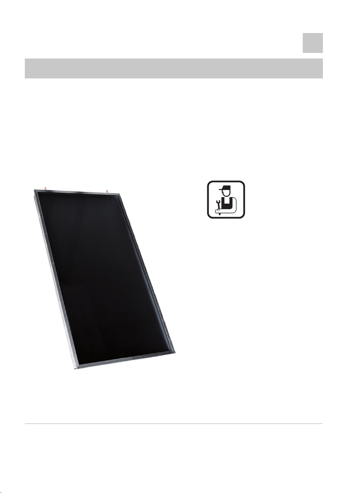
Flat solar panels
NEO 2.1 / SUN 211
EN
Installation and
Service Manual
Roof-integral
Installation
17° to 65°
mechanical tiles
300024195-001-02
Page 2

Contents
1 Introduction ................................................................................................4
1.1 Symbols used .......................................................4
1.2 General ..................................................................5
1.2.1 Manufacturer’s liability .............................................5
1.2.2 Installer’s liability .....................................................5
1.2.3 User’s liability ..........................................................5
2 Safety instructions and recommendations ..............................................7
2.1 Safety instructions ...............................................7
2.2 Recommendations ................................................7
3 Technical description ................................................................................8
3.1 Operating principle ...............................................8
3.2 Technical specifications ......................................8
3.2.1 Solar collectors ........................................................8
3.2.2 Load loss curve .......................................................9
4 Installation ................................................................................................10
4.1 Regulations governing installation ...................10
4.2 Package list .........................................................11
4.3 Main dimensions .................................................14
4.4 Installation diagrams ..........................................15
4.4.1 Vertical assembly, juxtaposed ...............................15
4.4.2 Example of an installation .....................................16
4.5 Assembling the solar collectors .......................17
4.5.1 Warning .................................................................17
4.5.2 Tools required .......................................................18
4.5.3 Dimensions ...........................................................19
4.5.4 Clearance to allow for ...........................................20
4.5.5 Fitting the battens ..................................................21
4.5.6 Mounting for an installation with 2 collectors .........22
4.5.7 Mounting for a system with up to 5 collectors .......37
4.5.8 Mounting for an installation with 1 collector ..........55
4.5.9 Put the tiles in place ..............................................66
4.6 Hydraulic connections .......................................67
4.6.1 Connection dimensions .........................................67
4.6.2 Connecting ............................................................67
4.6.3 Pipe insulation .......................................................68
1
20/02/2013 - 300024195-001-02
Page 3

Contents
4.7 Filling the system ...............................................68
5 Commissioning ........................................................................................70
5.1 Check points before commissioning ................70
5.2 Commissioning ...................................................70
6 Checking and maintenance .....................................................................71
6.1 General instructions ...........................................71
7 Spare parts ................................................................................................72
7.1 General ................................................................72
7.2 Spare parts ..........................................................72
2
20/02/2013 - 300024195-001-02
Page 4

3
20/02/2013 - 300024195-001-02
Page 5
NEO 2.1 / SUN 211 1. Introduction
1 Introduction
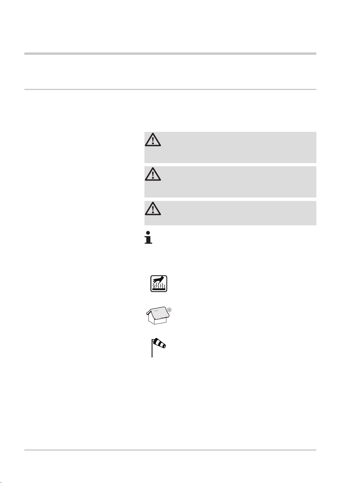
1.1 Symbols used
In these instructions, various danger levels are employed to draw the
user’s attention to particular information. In so doing, we wish to
safeguard the user’s safety, obviate hazards and guarantee correct
operation of the appliance.
DANGER
Risk of a dangerous situation causing serious physical
injury.
WARNING
Risk of a dangerous situation causing slight physical
injury.
CAUTION
Risk of material damage.
Signals important information.
¼Signals a referral to other instructions or other pages in the
instructions.
Caution: Risk of being burnt.
Zone susceptible to snow.
Zone susceptible to windy conditions.
20/02/2013 - 300024195-001-02
4
Page 6

1. Introduction
1.2 General
NEO 2.1 / SUN 211
1.2.1. Manufacturer’s liability
Our products are manufactured in compliance with the requirements
of the various applicable European Directives. They are therefore
delivered with [ marking and all relevant documentation.
In the interest of customers, we are continuously endeavouring to
make improvements in product quality. All the specifications stated in
this document are therefore subject to change without notice.
Our liability as the manufacturer may not be invoked in the following
cases:
4 Failure to abide by the instructions on using the appliance.
4 Faulty or insufficient maintenance of the appliance.
4 Failure to abide by the instructions on installing the appliance.
1.2.2. Installer’s liability
The installer is responsible for the installation and inital start up of the
appliance. The installer must respect the following instructions:
4 Read and follow the instructions given in the manuals provided
with the appliance.
4 Carry out installation in compliance with the prevailing legislation
and standards.
4 Perform the initial start up and carry out any checks necessary.
4 Explain the installation to the user.
4 If a maintenance is necessary, warn the user of the obligation to
check the appliance and maintain it in good working order.
4 Give all the instruction manuals to the user.
1.2.3. User’s liability
To guarantee optimum operation of the appliance, the user must
respect the following instructions:
4 Read and follow the instructions given in the manuals provided
with the appliance.
4 Call on qualified professionals to carry out installation and initial
start up.
4 Get your installer to explain your installation to you.
4 Have the required checks and services done.
4 Keep the instruction manuals in good condition close to the
appliance.
5
20/02/2013 - 300024195-001-02
Page 7

NEO 2.1 / SUN 211 1. Introduction
This appliance is not intended to be used by persons (including
children) whose physcial, sensory or mental capacity is impaired or
persons with no experience or knowledge, unless they have the
benefit, through the intermediary of a person responsible for their
safety, of supervision or prior instructions regarding use of the
appliance. Care should be taken to ensure that children do not play
with the appliance.
To prevent hazardous situations from arising, if the mains lead is
damaged it must be replaced by the original manufacturer, the
manufacturer’s dealer or another suitably skilled person.
20/02/2013 - 300024195-001-02
6
Page 8

2. Safety instructions and recommendations
2 Safety instructions and
recommendations
2.1 Safety instructions
DANGER
The permissible roof load of the building must not at any
time be exceeded. If necessary, a structural engineer
should be consulted before commencing work.
WARNING
Only a qualified professional may carry out the installation
in conformity with in force legislation and standards.
NEO 2.1 / SUN 211
2.2 Recommendations
CAUTION
Do not neglect to service the appliance. Contact a qualified
professional or take out a maintenance contract for the
annual servicing of the appliance.
WARNING
4 Any operation on the installation must be performed
by a qualified technician respecting professional
regulations and in accordance with this document.
4 When making the connections, it is imperative that
the standards and corresponding local directives are
respected.
4 The flat solar panels and fittings should be handled carefully during
transportation and storage. If the packing has nevertheless been
damaged during transit, the damage must be reported
immediately to and claimed against the carrier.
4 The contents of the assembly kit must be checked before
installation against the list which accompnaies each kit.
4 When installing the panels, take note of the safety instructions in
this document.
4 The packing material should be properly disposed of after
installation.
4 Insulate the pipes in rooms that are not heated (cellars and lofts).
4 Check regularly that the installation contains water and is
pressurised.
4 Service the appliance regularly to ensure that it operates correctly.
7
20/02/2013 - 300024195-001-02
Page 9
NEO 2.1 / SUN 211 3. Technical description
3 Technical description
3.1 Operating principle
The short-wave solar radiation (sunlight) striking the solar panel is
converted into heat by the selective coating on the absorber. From
there it is transferred by heat conduction to the absorber pipe and
carried by the heat-transporting fluid to the calorifier. The solar-panel
fluid heats the calorifier by means of the energy absorbed from the
sun and cools down itself in the process. The cooled heat-transporting
fluid then flows back to the solar panel in order to collect more solar
energy. An intelligent control system ensures that the circulation
system is only active when there is sufficient solar radiation, thus
optimising the collection of solar energy.
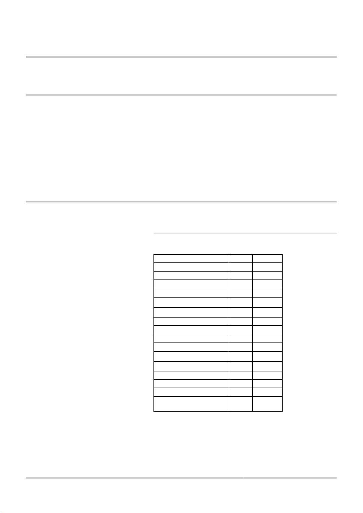
3.2 Technical specifications
3.2.1. Solar collectors
Length mm 1960
Width mm 1060
Height mm 70
Weight kg 34,45
Gross collector area A
Inlet surface Aa
Absorber surface A
Water content litres 1,2
Maximum operating pressure bar 10
Testing pressure bar 15
Optical efficiency η
Loss rating a
Loss rating a
Stagnation temperature °C 180
Hydraulic connections mm 12
Pressure drop mbar See below
Fitted tilt angle
minimum/maximum
1
2
G
A
o
2
m
2
m
2
m
W/m2.K
W/m2.K
° 17 to 65
2,1
1,88
1,90
0,773
3,676
0,0143
20/02/2013 - 300024195-001-02
8
Page 10

0
50
100
150
200
250
300
350
400
0 50 100 150 200 250 300
1
2
M002031-A
3. Technical description NEO 2.1 / SUN 211
3.2.2. Load loss curve
A
Z
Pressure drop (mbar)
Mass flow (Kg/h)
9
20/02/2013 - 300024195-001-02
Page 11

M001788-A
M002132-A
NEO 2.1 / SUN 211
4 Installation
4.1 Regulations governing installation
CAUTION
The installation must be equipped with a protective plastic
film (roof underlay film).
CAUTION
4 The installation must comply in all matters to the
4 The installation and maintenance of the appliance
4 Before installation, make sure that the framework is
4 Solar installations must be earthed to protect them
4 Protection of the environment: Place a container of
4 The roof mounting pack makes it possible to install
4. Installation
standards and rules which govern the work and
interventions in individual and collective homes, and
other constructions.
must be carried out by a qualified professional in
compliance with the statutory texts of the codes of
conduct in force.
solid and strong enough to comply with the static
requirements.
against lightning.
sufficient volume under the drain pipe and the valve
discharge pipe.
the solar collectors on roofs with structures
presenting a minimum incline of 17°.
20/02/2013 - 300024195-001-02
4 The roof-integral installation set is designed specifically as a
mounting system for the NEO 2.1 flat solar panels and may only
be used in accordance with their building regulations approval.
4 The mounting kit is designed for roof coverings in standard
mechanical roman roof tiles for the South of France.
4 The water drainage channels on the membrane should run into
the eaves (roof gutter).
4 The installation should therefore not be flushed or filled when the
collectors are hot (in strong sunshine).
4 The solar system must at all times be filled with heat transporting
fluid.
10
Page 12
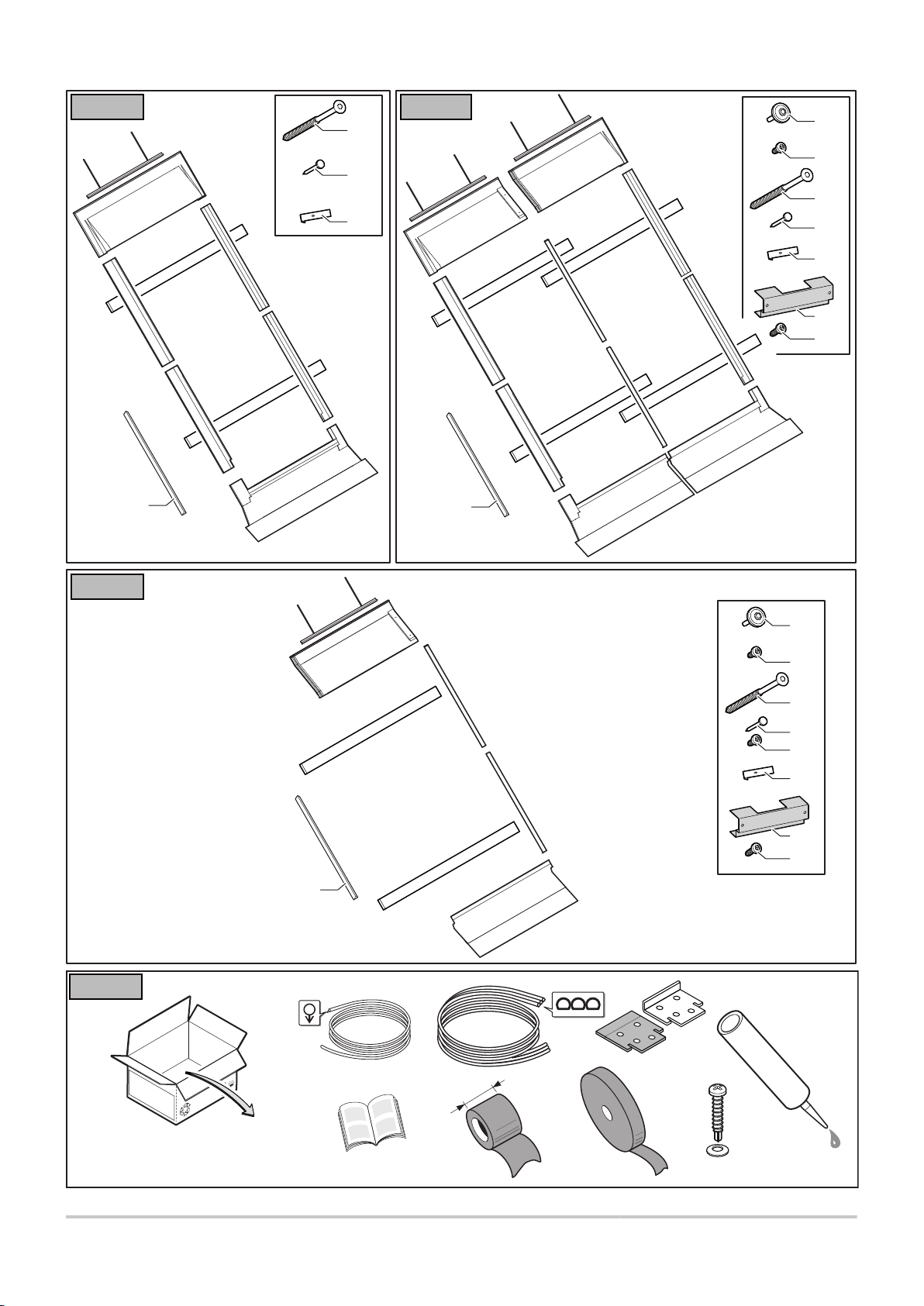
M001801-B
ER45 ER193
(5x)
(5x)
(2x)
(2x)
M001802-B
ER194 ER195
(10x)
(10x)
(4x)
(4x)
(5x)
(5x)
(2x)
(2x)
4. Installation NEO 2.1 / SUN 211
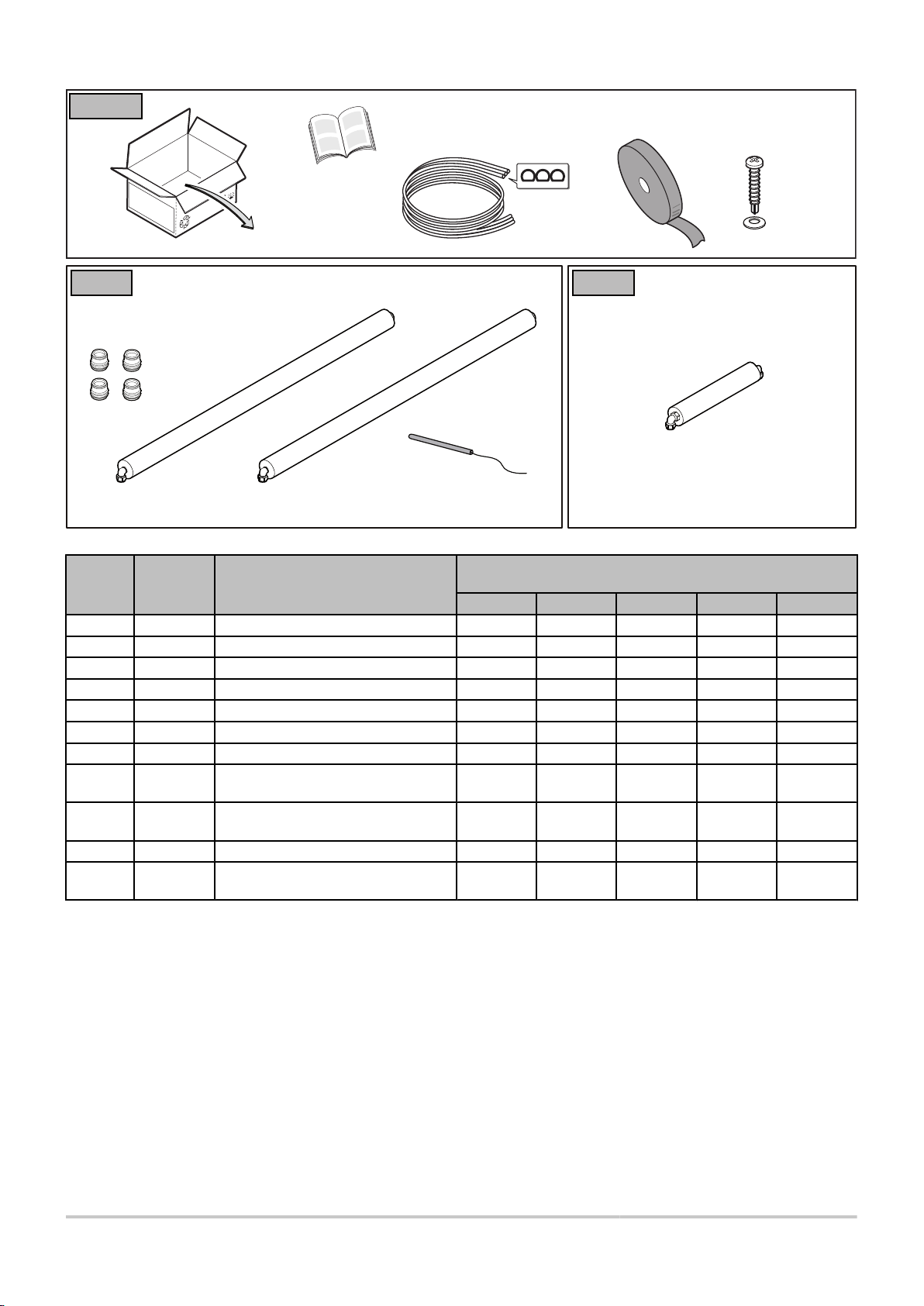
4.2 Package list
11
20/02/2013 - 300024195-001-02
Page 13
M002133-C
ER190 ER191
(7x)
(7x)
(10x)
(10x)
(10x)
(12x)
(2x)
(1x)
(2x)
(20x)
(12x)
(1x)
M002134-C
ER192
(1x)
(2x)
(2x)
(1x)
(1x)
(2x)
(2x)
(2x)
(1x)
30
ER236
C003463-C
NEO 2.1 / SUN 211 4. Installation
20/02/2013 - 300024195-001-02
12
Page 14
ER235
C003478-D
M001805-A
ER67 ER68
4. Installation NEO 2.1 / SUN 211
Pack no. Article no. Description Packages needed to construct the installation depending
on the number of solar collectors
1 2 3 4 5
ER 45 100013471 Solar collector 1 2 3 4 5
ER 193 100017965 Mounting kit 1 panel 1
ER 194 100017966 Mounting kit for 2 collectors
ER 195 100017967 Mounting kit for extension
ER 190 100015204 Sheet metal plate kit for 1 collector 1
ER 191 100015205 Sheet metal plate kit for 2 collectors
ER 192 100015206 Sheet metal plate kit for extension
ER 235 100017997 Waterproofing kit for integration of 1
collectors
ER 236 100017998 Waterproofing kit for integration of 2
collectors
ER 67 100013503 Hydraulic connection kit 1 1 1 1 1
ER 68 100013504 Hydraulic connection kit: Bridge 180°
DN12 230 mm
1
1 1 1 1
1 2 3
1 1 1 1
1 2 3
1 2 3 4
1 2 3 4
13
20/02/2013 - 300024195-001-02
Page 15
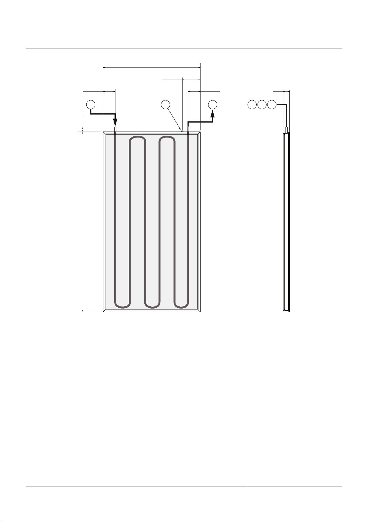
M001740-A
1060
113,5 113,5
175,5
371960
70
3
2
1 2 31
NEO 2.1 / SUN 211 4. Installation
4.3 Main dimensions
A
Z
E
Solar collector inlet
Solar collector outlet
Solar sensor probe
20/02/2013 - 300024195-001-02
14
Page 16
M001754-B
A
M001775-B
A
4. Installation NEO 2.1 / SUN 211
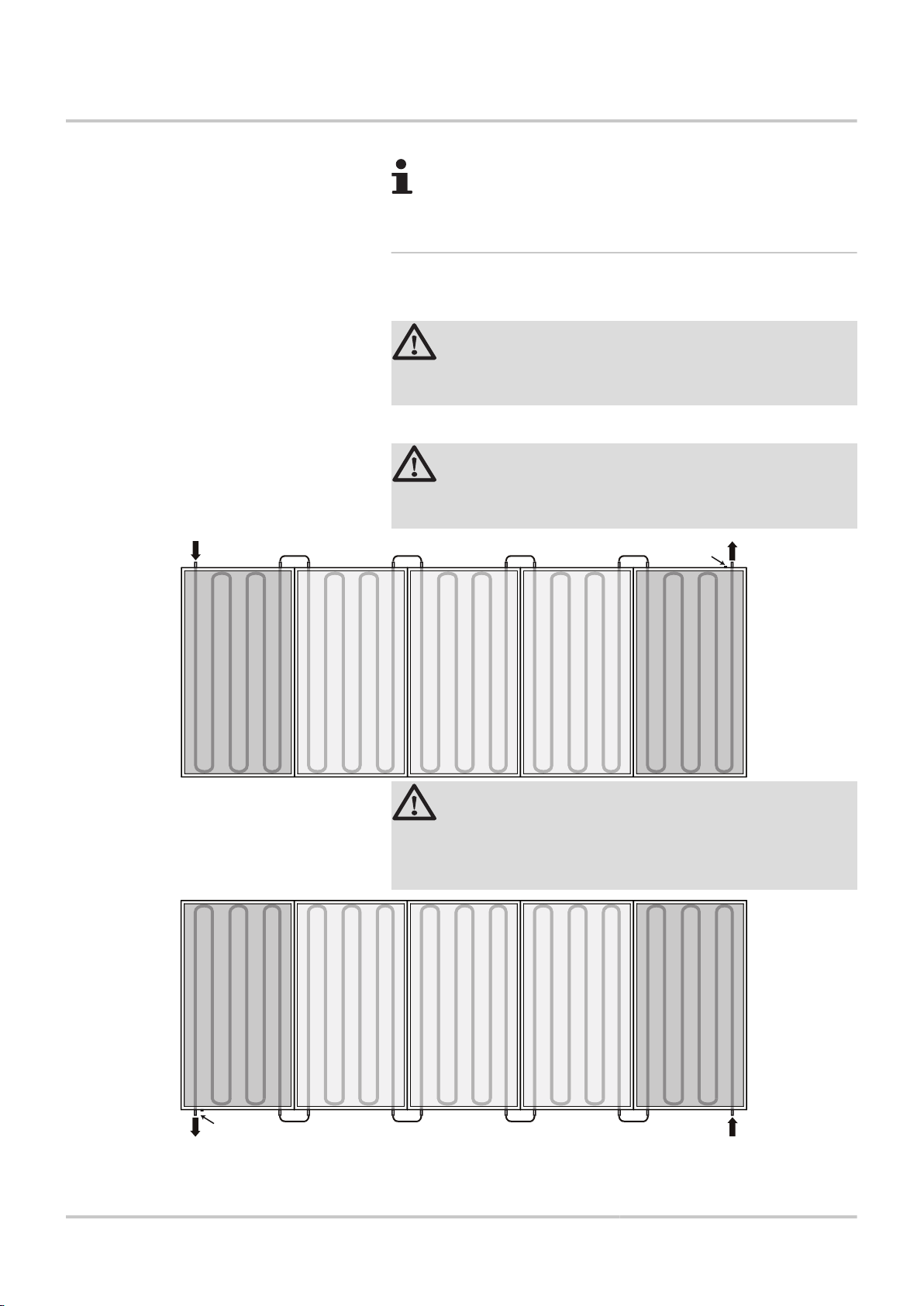
4.4 Installation diagrams
It is permitted to assemble a maximum of 5 interlinked
collectors.
4.4.1. Vertical assembly, juxtaposed
4 Connection for 1 to 5 collectors.
CAUTION
Place the collector sensor on the flow side of the solar
circuit (flow from the hottest collector).
A: Solar sensor probe.
CAUTION
Recommended mounting: Sensor A located at the top of
the collector.
15
CAUTION
If sensor A is located at the bottom of the collector, it is
necessary to use a batten from your delivery of a max.
height of 45 mm (¼ "Dimensions", page 19).
20/02/2013 - 300024195-001-02
Page 17
M001806-C
109
130
89
230V
50Hz
114
61
88
61 61
87
85
4
84
114
NEO 2.1 / SUN 211 4. Installation
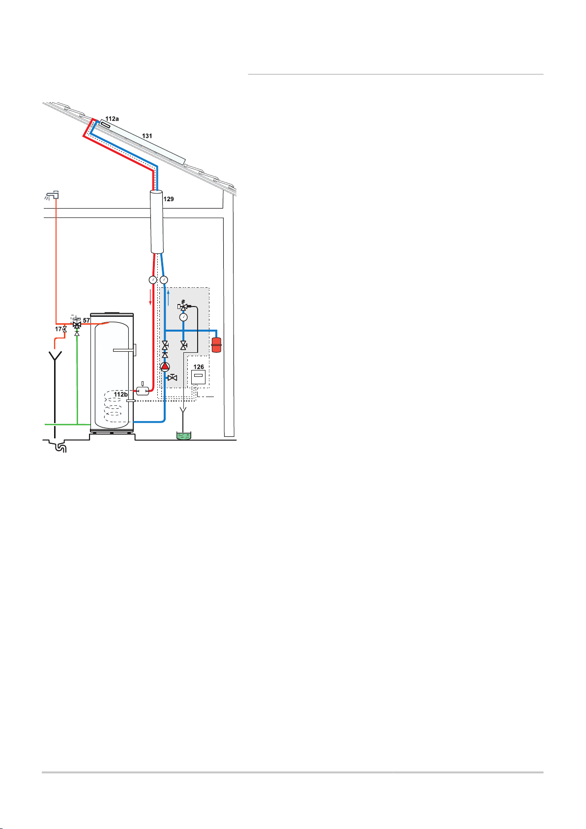
4.4.2. Example of an installation
4
17
57
61
84
85
87
88
89
109
112a
112b
114
126
129
130
131
Pressure gauge
Drain cock
Domestic hot water outlet
Thermometer
Stop valve with releasable non-return valve
Primary solar circuit pump
6-bar calibrated safety valve (primary solar)
Expansion vessel
Heat transfer fluid container
Domestic hot water thermostatic mixing valve
Solar sensor probe
Domestic hot water sensor
Solar circuit drainage valve
Solar regulator
Duo-Tube
Manual bleed degasser
Flat or tubular solar panel
20/02/2013 - 300024195-001-02
16
Page 18
M001748-A
4. Installation NEO 2.1 / SUN 211
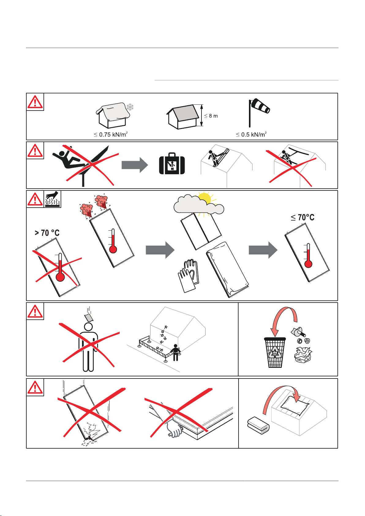
4.5 Assembling the solar collectors
4.5.1. Warning
17
20/02/2013 - 300024195-001-02
Page 19
M001719-B
10 10
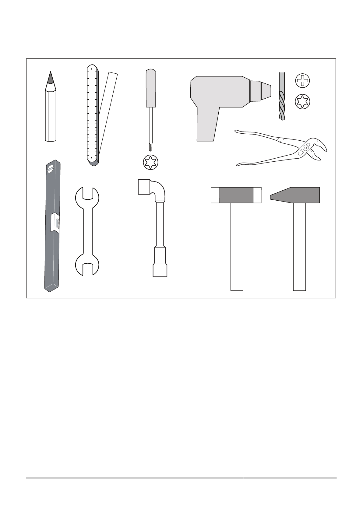
NEO 2.1 / SUN 211 4. Installation
4.5.2. Tools required
20/02/2013 - 300024195-001-02
18
Page 20
M002135-D
4
4 4 4 4
370
430
1980
2410
A
400 66066016580
10
10
17-65°
550
3
5
2
1
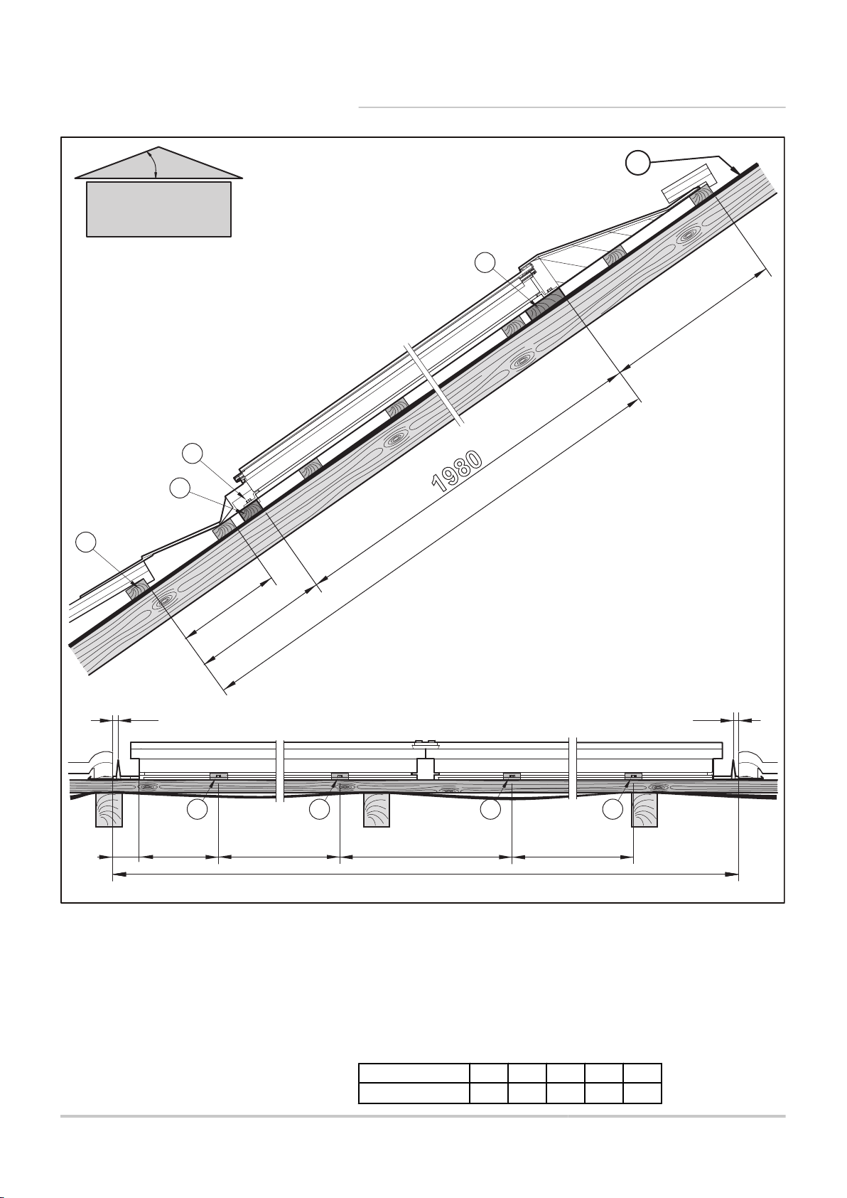
4. Installation NEO 2.1 / SUN 211
4.5.3. Dimensions
19
A
Z
E
R
T
Number of panels 1 2 3 4 5
Size A 1147 2210 3273 4336 5400
Existing batten
Starting batten to be laid, not provided (Width: 45 mm)
Fastening batten to be fitted supplied
Fixing lugs to be put in place on the starting batten
Protective tarpaulin
20/02/2013 - 300024195-001-02
Page 21
M002136-B
>A
>3700
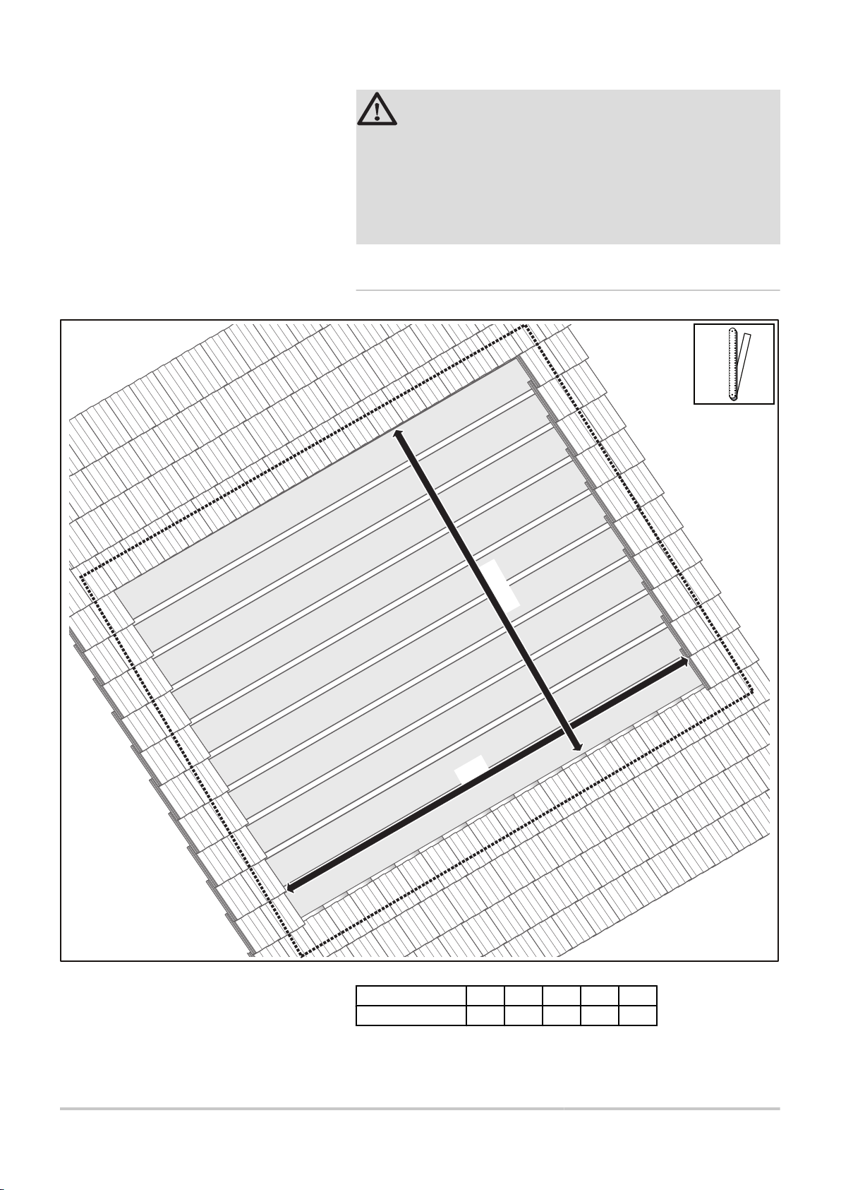
NEO 2.1 / SUN 211 4. Installation
CAUTION
4 Make sure that the roof liner sheet has been
fitted. If not, fit the protective plastic sheet.
4 Battens Z, E and R must be of the same thickness
as the existing battens.
4 Respect the dimension of 550 mm. If necessary, add
an extra batten.
4.5.4. Clearance to allow for
20/02/2013 - 300024195-001-02
Number of panels 1 2 3 4 5
Size A 1920 2980 4040 5100 6160
20
Page 22
M002137-C
370
1980
430
550
=
=
1
1
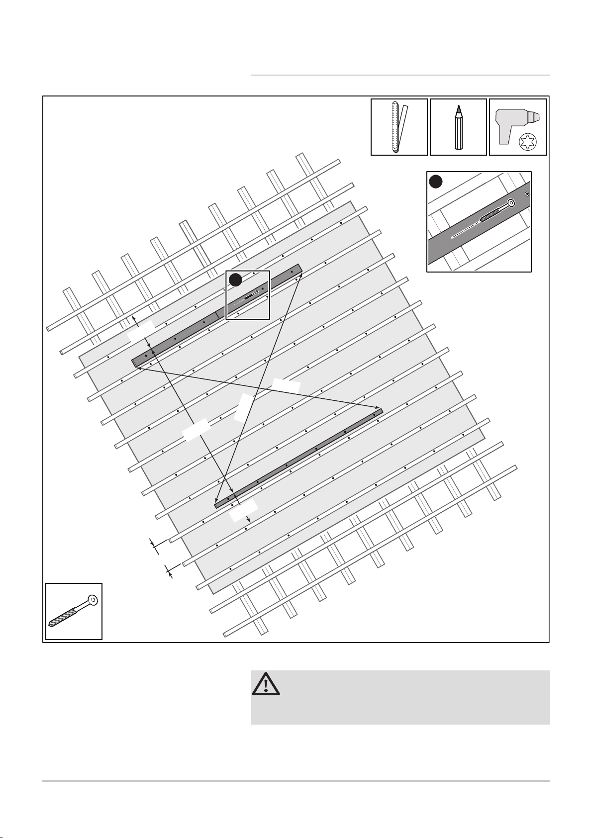
4. Installation NEO 2.1 / SUN 211
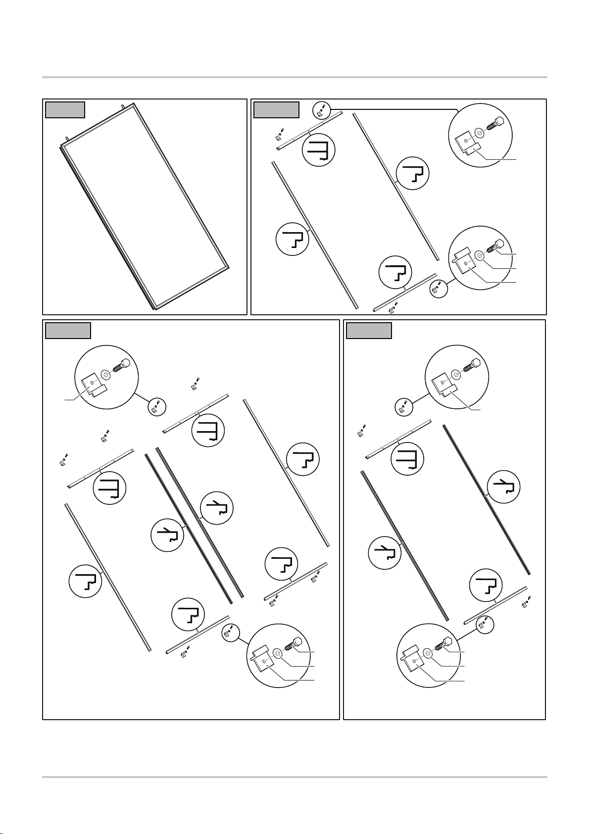
4.5.5. Fitting the battens
A
Secure the battens using the screws provided.
21
CAUTION
Respect the dimension of 550 mm. If necessary, add an
extra batten.
20/02/2013 - 300024195-001-02
Page 23
C003456-F
660
400
200
mini
660
1
2
3
3
3
3
3
1 2
1 2
1 2
1 2
80
165
NEO 2.1 / SUN 211
4.5.6. Mounting for an installation with 2
collectors
Positioning the solar collectors
n
4. Installation
1. Screw the lower fastening lugs onto the bottom batten.
2. Position the collectors. The fastening lugs must be fitted into the
holding groove.
3. Postion the upper fastening lugs in the holding groove on the
collectors and screw them onto the batten.
The solar panels should only be installed shortly before the solarheating system is to be commissioned. This will minimise the time that
the solar panels are exposed to heat while not filled with heattransporting fluid.
20/02/2013 - 300024195-001-02
22
Page 24

C003457-A
A
A
A
1
3
3
3
3
3
1
1
2
2
2
4. Installation
Fitting the intermediary seals and clips
n
NEO 2.1 / SUN 211
23
1. Clean the support surface.Fit the seal, without the clamp, into the
groove along the entire height of the 2 collectors.
2. Clean the surface before fitting the flat seal to it. Glue the
intermediary flat seal to the 2 collectors.
3. Fit the intermediary clips using the mallet, aligning them with the
bottom of the collectors.
20/02/2013 - 300024195-001-02
Page 25

C003458-C
B
B
B
B
B
A
1
1
2
NEO 2.1 / SUN 211 4. Installation
Assembling and securing the 2 collectors
n
20/02/2013 - 300024195-001-02
1. Slide the second solar panel up to the first. The collectors must be
fitted perfectly edge to edge.
2. Secure the collectors.
24
Page 26

A
C003459-B
A
1
2
3
2
1
3
3
3
3
3
A
4. Installation
Fitting the upper seals and clips
n
NEO 2.1 / SUN 211
25
1. Clean the support surface. Fit the seal, without the clamp, into the
upper groove on the 2 collectors.
2. Clean the surface before fitting the flat seal to it. Glue the flat seal
along the entire width of the 2 collectors.
3. Fit the upper clips using the mallet.
20/02/2013 - 300024195-001-02
Page 27

C003460-E
1
3
6
7
5
4
3
40
2
NEO 2.1 / SUN 211
Waterproofing the connection between the 2
n
collectors (upper)
4. Installation
1. Clean the support surface. Glue the BUTYL strip to the
intermediary clips, leaving 3 mm clearance.
2. Leave the BUTYL strip loose at the end of the intermediate clips.
3. Squeeze silicone on to the joints between the mounting
components.
4. Remove the protective film from the self-adhesive foam.
5. Glue the self-adhesive foam to the covering plate.
6. Cover the upper part of the covering plate with silicone.
7. Fit the covering plate, secure it and spread a veil of silicone over
it.
20/02/2013 - 300024195-001-02
26
Page 28

C003462-C
4. Installation NEO 2.1 / SUN 211
Fitting the foam seal
n
1. Clean the surface to which the foam seal is to be fitted.
2. Glue the foam seal to the top of the upper clip.
27
20/02/2013 - 300024195-001-02
Page 29

M002140-C
C + D
A
B
B
A
C
D
1
2
NEO 2.1 / SUN 211
Connecting the solar collectors
n
4. Installation
CAUTION
Install the temperature sensor in the sensor tube on the
solar collector, at the flow end of the bank of collectors.
The transfer of heat between the sensor socket and the
temperature sensor can be improved by the use of heatconducting paste on the temperature sensor.
1. Fit the collector/tank connections. Tighten the clamping ring screw
connections correctly.
2. Fit the temperature sensor. Push the temperature sensor through
the gasket.
20/02/2013 - 300024195-001-02
28
Page 30

A
B
M002320-A
4. Installation NEO 2.1 / SUN 211
Passing Pipes and Cable through the Roof
n
29
A
Scenario with two overlapping sheets of film under the
roof
B
Scenario with a single sheet of film under the roof
20/02/2013 - 300024195-001-02
Page 31

C003461-F
1
2
NEO 2.1 / SUN 211 4. Installation
Fitting the lower flat seal
n
Fit the flat seal along the lower part of the 2 collectors
1. Clean the surface before fitting the flat seal to it. Glue the flat seal.
Remove the self-adhesive tape at the top of the flat seal.
2. Cut the flat seal to the correct length.
20/02/2013 - 300024195-001-02
30
Page 32

M002141-F
1
3
4
2
4
3
A
A
A-A
4. Installation
Mounting the lower roofing plates
n
NEO 2.1 / SUN 211
CAUTION
4 If the collectors are mounted with the flow and return
connections at the bottom, reposition and tighten the
fittings before putting the lower roofing plate in place.
4 Check that the rigid flap is flush against the ridge
tiles. The lead flap should be moulded to the shape
of the tiles in order to allow as little daylight as
possible between tiles and flap along the entire
length.
1. Position the lower right roofing plate.
2. Position the lower left roofing plate.
31
20/02/2013 - 300024195-001-02
Page 33

C003923-C
2
4
5
6
6
3
1
NEO 2.1 / SUN 211
4. Installation
3. Put the lower right roofing plate in place. Put the lower right clip in
place.
4. Put the lower left roofing plate in place. Put the lower left clip in
place.
Waterproofing the connection between the 2
n
collectors (lower)
20/02/2013 - 300024195-001-02
1. Leave the BUTYL strip loose at the end of the intermediate clips.
Squeeze silicone on to the joints between the mounting
components.
2. Coat the inside of the central junction section with silicone.
3. Put the central junction section in place.
4. Coat the sections with silicone.
32
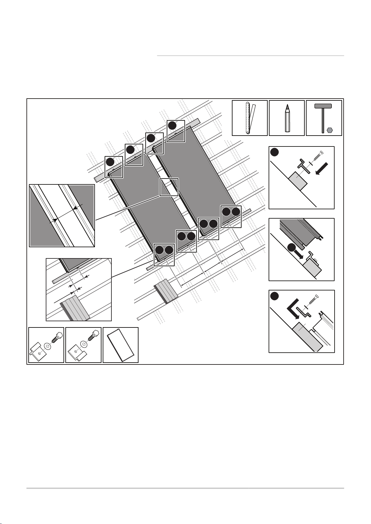
Page 34

M002142-F
7
8
1
2
3
4
5
6
7
8
A
D
E
B
B
C
9
9
4. Installation
NEO 2.1 / SUN 211
5. Fold the BUTYL strip back on to the junction section.
6. Secure the junction section.
Mounting the side roofing plates
n
33
1. Put the left side flaps A and B in place.
- Flap A should be placed as far over flap B as it can go to cover
it.
- Flaps A and B should be correctly aligned.
20/02/2013 - 300024195-001-02
Page 35

NEO 2.1 / SUN 211 4. Installation
2. Place the assembly of A + B on the lower flap.
- Flap A should be flush with the top of the collector.
- Flap B should be aligned with the bottom of the lower sheet metal
plate.
3. Fit the side clip C.
4. Put the right side flaps D and E in place.
5. Place the assembly of D + E on the lower flap.
- Flap D should be flush with the top of the collector.
- Flap E should be aligned with the bottom of the lower sheet metal
plate.
6. Fit the side clip F.
7. Put the upper junction part in place.
8. Put the lower junction part in place.
9. Put the screw in place.
20/02/2013 - 300024195-001-02
34
Page 36

M002143-D
1
2
3
4. Installation
Mounting the upper roofing plates
n
NEO 2.1 / SUN 211
CAUTION
If the collectors are mounted with the flow and return
1. Hook the right roofing plate on to the upper clip. Fold the assembly
over downwards while pulling the part upwards.
connections at the top, reposition and tighten the fittings
before putting the upper roofing plate in place.
35
20/02/2013 - 300024195-001-02
Page 37

M002144-C
2
3
1
1
1
2
1 1 2 3
3
NEO 2.1 / SUN 211
4. Installation
2. Hook the left roofing plate on to the upper clip. Fold the assembly
over downwards while pulling the part upwards.
Check that the lugs on the side flaps are slotted into the
part on top of the roofing units.
3. Insert the screws.
Fitting the fastening lugs and the tile rests
n
20/02/2013 - 300024195-001-02
1. Secure the side flaps and the top flaps with the sheet metal plates
.
2. Position the left tile rest on the upper flap 10 cm from the top.
Fit the flap to one of the battens using straps.
Cut the battens added to the original battening level with the side
flaps.
36
Page 38

M002149-D
(7x)
1
2
2
2
2
4. Installation NEO 2.1 / SUN 211
3. Position the right tile rest on the upper flap 10 cm from the top.
Fit the flap to one of the battens using straps.
Cut the battens added to the original battening level with the side
flaps.
Putting the foam in place
n
1. Remove the self-adhesive strip.
Clean the outside edge of the side lugs.
Glue the foam strips along the entire length of the kit without
leaving any space (from the lead lug to the top).
2. Glue the foam to the edge of the side and top roofing plates. If
need be, adjust to the correct length with a Stanley knife.
Check the corners of the lead flaps. The overhanging lead should
be turned over upwards with a downward roof gradient along the
width and length fitted under the tiles.
4.5.7. Mounting for a system with up to 5
collectors
CAUTION
It is permitted to assemble a maximum of 5 interlinked
collectors.
37
20/02/2013 - 300024195-001-02
Page 39

C003456-F
660
400
200
mini
660
1
2
3
3
3
3
3
1 2
1 2
1 2
1 2
80
165
NEO 2.1 / SUN 211
Positioning the solar collectors
n
4. Installation
1. Screw the lower fastening lugs onto the bottom batten.
2. Position the collectors. The fastening lugs must be fitted into the
holding groove.
3. Postion the upper fastening lugs in the holding groove on the
collectors and screw them onto the batten.
The solar panels should only be installed shortly before the solarheating system is to be commissioned. This will minimise the time that
the solar panels are exposed to heat while not filled with heattransporting fluid.
20/02/2013 - 300024195-001-02
38
Page 40

1
1
C003467-B
A
A
A
A
A
1
3
3
3
3
3
3
3
3
3
1 2
2
2
2
4. Installation
Fitting the intermediary seals and clips
n
NEO 2.1 / SUN 211
1. Clean the support surface. Fit the seal, without the clamp, into the
groove along the entire height of the 2 collectors.
2. Clean the surface before fitting the flat seal to it. Glue the
intermediary flat seal to the 2 collectors.
3. Fit the intermediary clips using the mallet, aligning them with the
bottom of the collectors.
39
20/02/2013 - 300024195-001-02
Page 41

C003468-C
B
B
B
B
B
A
1
1
2
NEO 2.1 / SUN 211 4. Installation
Assembling and securing the 3 collectors
n
1. Slide the second solar panel up to the first. The collectors must be
fitted perfectly edge to edge.
2. Secure the collectors.
20/02/2013 - 300024195-001-02
40
Page 42

A
A
C003469-A
A
1
2
3
2
1
3
3
3
3
3
3
3
A
4. Installation
Fitting the upper seals and clips
n
NEO 2.1 / SUN 211
41
1. Clean the support surface. Fit the seal, without the clamp, into the
upper groove on the 2 collectors.
2. Clean the surface before fitting the flat seal to it. Glue the flat seal
along the entire width of the 2 collectors.
3. Fit the upper clips using the mallet.
20/02/2013 - 300024195-001-02
Page 43

C003470-B
1
3
6
7
5
4
3
40
2
NEO 2.1 / SUN 211
Waterproofing the connection between the 3
n
collectors (upper)
4. Installation
1. Clean the support surface. Glue the BUTYL strip to the
intermediary clips, leaving 3 mm clearance.
2. Leave the BUTYL strip loose at the end of the intermediate clips.
3. Squeeze silicone on to the joints between the mounting
components.
4. Remove the protective film from the self-adhesive foam.
5. Glue the self-adhesive foam to the covering plate.
6. Cover the upper part of the covering plate with silicone.
7. Fit the covering plate, secure it and spread a veil of silicone over
it.
20/02/2013 - 300024195-001-02
42
Page 44

C003472-C
4. Installation NEO 2.1 / SUN 211
Fitting the foam seal
n
1. Clean the support surface.
2. Glue the foam seal to the top of the upper clip.
43
20/02/2013 - 300024195-001-02
Page 45

M002307-D
C + D
A
B
B
B
A
C
D
1
2
NEO 2.1 / SUN 211
Connecting the solar collectors
n
4. Installation
CAUTION
Install the temperature sensor in the sensor tube on the
solar collector, at the flow end of the bank of collectors.
The transfer of heat between the sensor socket and the
temperature sensor can be improved by the use of heatconducting paste on the temperature sensor.
20/02/2013 - 300024195-001-02
1. Fit the collector/tank connections. Tighten the clamping ring screw
connections correctly.
2. Fit the temperature sensor. Push the temperature sensor through
the gasket.
44
Page 46

A
B
M002320-A
4. Installation NEO 2.1 / SUN 211
Passing Pipes and Cable through the Roof
n
45
A
Scenario with two overlapping sheets of film under the
roof
B
Scenario with a single sheet of film under the roof
20/02/2013 - 300024195-001-02
Page 47

C003471-F
1
2
NEO 2.1 / SUN 211 4. Installation
Fitting the lower flat seal
n
Fit the flat seal along the lower part of the 3 collectors
1. Clean the surface before fitting the flat seal to it. Glue the flat seal.
Remove the self-adhesive tape at the top of the flat seal.
2. Cut the flat seal to the correct length.
20/02/2013 - 300024195-001-02
46
Page 48

M002308-F
1
4
3
6
2
5
A
A
4
5 6
A-A
4. Installation NEO 2.1 / SUN 211
Mounting the lower roofing plates
n
47
20/02/2013 - 300024195-001-02
Page 49

NEO 2.1 / SUN 211 4. Installation
CAUTION
4 If the collectors are mounted with the flow and return
connections at the bottom, reposition and tighten the
fittings before putting the lower roofing plate in place.
4 Check that the rigid flap is flush against the ridge
tiles. The lead flap should be moulded to the shape
of the tiles in order to allow as little daylight as
possible between tiles and flap along the entire
length.
1. Position the lower right roofing plate.
2. Position the lower central roofing plate.
3. Position the lower left roofing plate.
4. Put the lower right roofing plate in place. Put the lower right clip in
place.
5. Put the lower central roofing plate in place. Put the lower central
clip in place.
6. Put the lower left roofing plate in place. Put the lower left clip in
place.
20/02/2013 - 300024195-001-02
48
Page 50

C003924-B
2
4
5
6
6
3
1
4. Installation
Waterproofing the connection between the 3
n
collectors (lower)
NEO 2.1 / SUN 211
1. Leave the BUTYL strip loose at the end of the intermediate clips.
Squeeze silicone on to the joints between the mounting
components.
2. Coat the inside of the central junction section with silicone.
3. Put the central junction section in place.
4. Coat the sections with silicone.
5. Fold the BUTYL strip back on to the junction section.
6. Secure the junction section.
49
20/02/2013 - 300024195-001-02
Page 51

M002309-G
1
2
3
4
5
6
7
8
8
7
8
9
9
7
A
B
D
E
F
B
C
9
NEO 2.1 / SUN 211
Mounting the side roofing plates
n
4. Installation
20/02/2013 - 300024195-001-02
1. Put the left side flaps A and B in place.
- Flap A should be placed as far over flap B as it can go to cover
it.
- Flaps A and B should be correctly aligned.
50
Page 52

4. Installation NEO 2.1 / SUN 211
2. Place the assembly of A + B on the lower flap.
- Flap A should be flush with the top of the collector.
- Flap B should be aligned with the bottom of the lower sheet metal
plate.
3. Fit the side clip C.
4. Put the right side flaps D and E in place.
- Flap D should be placed as far over flap E as it can go to cover
it.
- Flaps D and E should be correctly aligned.
5. Place the assembly of D + E on the lower flap.
- Flap D should be flush with the top of the collector.
- Flap E should be aligned with the bottom of the lower sheet metal
plate.
6. Fit the side clip F.
7. Put the upper junction parts in place.
8. Put the lower junction parts in place.
9. Insert the screws.
51
20/02/2013 - 300024195-001-02
Page 53

M002310-D
1
2
3
4
NEO 2.1 / SUN 211
Mounting the upper roofing plates
n
4. Installation
CAUTION
If the collectors are mounted with the flow and return
connections at the top, reposition and tighten the fittings
before putting the upper roofing plate in place.
1. Hook the right roofing plate on to the upper clip. Fold the assembly
over downwards while pulling the part upwards.
2. Hook the central roofing plate on to the upper clip. Fold the
assembly over downwards while pulling the part upwards.
20/02/2013 - 300024195-001-02
52
Page 54

M002311-C
2
3
4
1
1
1
1 1 2 3 4
2 3 4
4. Installation
NEO 2.1 / SUN 211
3. Hook the left roofing plate on to the upper clip. Fold the assembly
over downwards while pulling the part upwards.
Check that the lugs on the side flaps are slotted into the
part on top of the roofing units.
4. Insert the screws.
Fitting the fastening lugs and the tile rests
n
1. Secure the side flaps and the top flaps with the sheet metal plates
.
2. Position the left tile rest on the upper flap 10 cm from the top.
Fit the flap to one of the battens using straps.
Cut the battens added to the original battening level with the side
flaps.
53
20/02/2013 - 300024195-001-02
Page 55

M002312-E
(8x)
2
2
2
1
2
NEO 2.1 / SUN 211
4. Installation
3. Position the central tile rest on the upper flap 10 cm from the
top.
Fit the flap to one of the battens using straps.
Cut the battens added to the original battening level with the side
flaps.
4. Position the right tile rest on the upper flap 10 cm from the top.
Fit the flap to one of the battens using straps.
Cut the battens added to the original battening level with the side
flaps.
Putting the foam in place
n
1. Remove the self-adhesive strip.
Clean the outside edge of the side lugs.
Glue the foam strips along the entire length of the kit without
leaving any space (from the lead lug to the top).
2. Glue the foam to the edge of the side and top roofing plates. If
need be, adjust to the correct length with a Stanley knife.
Check the corners of the lead flaps. The overhanging lead should
be turned over upwards with a downward roof gradient along the
width and length fitted under the tiles.
20/02/2013 - 300024195-001-02
54
Page 56

660
M002313-H
165
80
1
3
3
1 2
1 2
2
3
4. Installation
NEO 2.1 / SUN 211
4.5.8. Mounting for an installation with 1 collector
Installing the solar collector
n
1. Screw the lower fastening lugs onto the bottom batten.
2. Fit the collector. The fastening lugs must be fitted into the holding
groove.
3. Postion the upper fastening lugs in the holding groove on the
collectors and screw them onto the batten.
Respect the dimension of 245 mm from the tiled area when
fitting the fastening lugs and 80 mm from the edge of the
tiles to the collector to avoid having to cut tiles along one
edge.
The solar collector must be mounted shortly before commissioning
the solar system. This minimises the time during which the collector
is heated pointlessly, without heat transporting fluid.
55
20/02/2013 - 300024195-001-02
Page 57

C003464-B
A
1
2
1
2
2
A
NEO 2.1 / SUN 211
Fitting the seal and the upper clip
n
4. Installation
1. Clean the surface before fitting the flat seal to it. Glue the flat seal.
2. Fit the upper clip using the mallet.
20/02/2013 - 300024195-001-02
56
Page 58

A
M002314-D
B + C
A
2
1
B
C
4. Installation
Connecting the solar collector
n
NEO 2.1 / SUN 211
CAUTION
Install the temperature sensor in the sensor tube on the
solar collector.
The transfer of heat between the sensor socket and the
temperature sensor can be improved by the use of heatconducting paste on the temperature sensor.
1. Fit the collector/tank connections. Tighten the clamping ring screw
connections correctly.
2. Fit the temperature sensor. Push the temperature sensor through
the gasket.
57
20/02/2013 - 300024195-001-02
Page 59

A
B
M002320-A
NEO 2.1 / SUN 211 4. Installation
Passing Pipes and Cable through the Roof
n
20/02/2013 - 300024195-001-02
A
Scenario with two overlapping sheets of film under the
roof
B
Scenario with a single sheet of film under the roof
58
Page 60

C003473-E
1
2
4. Installation NEO 2.1 / SUN 211
Fitting the lower flat seal
n
Put the flat seal in place along the entire lower length of the
collector
1. Clean the surface before fitting the flat seal to it. Glue the flat seal.
Remove the self-adhesive tape at the top of the flat seal
2. Cut the flat seal to the correct length.
59
20/02/2013 - 300024195-001-02
Page 61

M002315-E
B
1
2
3
A-A
A
A
NEO 2.1 / SUN 211
Fitting the lower roofing plate
n
4. Installation
20/02/2013 - 300024195-001-02
CAUTION
4 If the collector is mounted with the flow and return
connections at the bottom, reposition and tighten the
joints before fitting the lower roofing plate.
4 Check that the rigid flap is flush against the ridge
tiles. The lead flap should be moulded to the shape
of the tiles in order to allow as little daylight as
possible between tiles and flap along the entire
length.
1. Position the lower plate.
2. Put the lower sheet metal plate in place.
3. Fit the lower clip.
60
Page 62

M002316-G
1
2
3
4
5
6
A
D
B
E
F
C
B
4. Installation
Mounting the side roofing plates
n
NEO 2.1 / SUN 211
1. Put the left side flaps A and B in place.
- Flap A should be placed as far over flap B as it can go to cover
it.
- Flaps A and B should be correctly aligned.
2. Place the assembly of A + B on the lower flap.
- Flap A should be flush with the top of the collector.
- Flap B should be aligned with the bottom of the lower sheet metal
plate.
3. Fit the side clip C.
4. Put the right side flaps D and E in place.
- Flap D should be placed as far over flap E as it can go to cover
it.
- Flaps D and E should be correctly aligned.
61
20/02/2013 - 300024195-001-02
Page 63

C003465-C
NEO 2.1 / SUN 211 4. Installation
5. Place the assembly of D + E on the lower flap.
- Flap D should be flush with the top of the collector.
- Flap E should be aligned with the bottom of the lower sheet metal
plate.
6. Fit the side clip F.
Fitting the foam seal
n
1. Clean the support surface.
2. Glue the foam seal to the top of the upper clip.
20/02/2013 - 300024195-001-02
62
Page 64

M002317-E
1
2
4. Installation
Mounting the upper roofing plate
n
NEO 2.1 / SUN 211
CAUTION
If the collector is mounted with the flow and return
connections to the bottom, reposition and tighten the
fittings before positioning the upper roofing plate.
1. Hook the roofing plate into the upper clip. Fold the assembly over
downwards while pulling the part upwards.
2. Check that the lugs on the side flaps are slotted into the part on
top of the roofing units.
63
20/02/2013 - 300024195-001-02
Page 65

M002318-C
2
1
1
1
1 1 2
2
NEO 2.1 / SUN 211
Fitting the fastening lugs and the tile rests
n
4. Installation
1. Secure the side flaps and the top flaps with the sheet metal plates
.
2. Fit the tile rest to the top flap 10 cm from the top.
Fit the flap to one of the battens using straps.
Cut the battens added to the original battening level with the side
flaps.
20/02/2013 - 300024195-001-02
64
Page 66

M002319-E
(7x)
2
2
2
1
2
4. Installation NEO 2.1 / SUN 211
Putting the foam in place
n
1. Remove the self-adhesive strip.
Clean the outside edge of the side lugs.
Glue the foam strips along the entire length of the kit without
leaving any space (from the lead lug to the top).
2. Glue the foam to the edge of the side and top roofing plates. If
need be, adjust to the correct length with a Stanley knife.
Check the corners of the lead flaps. The overhanging lead should
be turned over upwards with a downward roof gradient along the
width and length fitted under the tiles.
65
20/02/2013 - 300024195-001-02
Page 67

1
2
3
3
1
2
M002146-D
NEO 2.1 / SUN 211 4. Installation
4.5.9. Put the tiles in place
A
Z
E
Ridge or bevelled tile
Roof tile to be cut according to position
Roof tile cut to approximately 260 mm
20/02/2013 - 300024195-001-02
66
Page 68

1 2 3
4
M001755-A
M001756-A
4. Installation
4.6 Hydraulic connections
NEO 2.1 / SUN 211
4.6.1. Connection dimensions
Number of panels Size
2 14-15 40 m
3 14-15 40 m
4 16-18 40 m
5 16-18 40 m
Maximum length
(mm)
(Outlet + Return)
To be able to have pipework without degassers or bleed valves at
high points, the solar fluid flow rate must not fall below 0,4 m/s during
the degassing procedure.
The pipes must be as short as possible and always sloping
downwards between the collectors and the connection to the solar
calorifier.
If the installation criteria for good degassing cannot be met, a manual
bleed degasser R must always be installed at the high point(s) of the
solar equipment.
A
Z
E
R
Ideal
Incorrect (high point with no air vent)
Correct (high point with air vent)
Location of manual bleed valve degasser
4.6.2. Connecting
CAUTION
Soft soldering are not authorized.
The use of flux promotes corrosion conditions in systems
operating with propylene glycol as heat transfer fluid. In all
cases the inside of the pipes must be flushed.
4 Use of a hacksaw is prohibited.
4 Pipe connections by compression unions.
4 Hard soldering: Hard soldering: hard soldering filler metal without
flux in accordance with DIN EN 1044, e.g. L-Ag2P or L-CuP6.
4 Pipe unions: can only be used if they are resistant to glycol,
pressure (6 bar) depending on version) and temperature (-30 °C,
180 °C) (manufacturer’s data).
4 Sealing material: Hemp.
4 Press fitting (6 bar, 140 °C).
67
20/02/2013 - 300024195-001-02
Page 69

M001704-A
NEO 2.1 / SUN 211
4. Installation
4.6.3. Pipe insulation
CAUTION
To protect the insulation against mechanical damage, bird
pecking and UV light, add extra protection for the heat
insulation sleeves in the roof area by using an aluminium
sheet sleeve or aluminium adhesive tape. This additional
protection must be sealed with silicone.
4 If different copper pipes are used, the insulation must be:
- Resistant to constant temperatures up to 150 °C in the collector
zone and the hot outlet and also down to - 30 °C.
- Insulation preferably waterproof and continuous.
- with a thickness equal to the tube diameter and with a K
coefficient of 0.04 W/mK.
50 % reduction of the insulation is permitted when passing
through the roof and walls.
4.7 Filling the system
4 Recommended materials for temperatures up to 150 °C:
- Duo-Tube
- DuoFlex
- Armaflex HT
- mineral wool
- glass fibre
CAUTION
4 Do not fill / rinse a hot solar collector. Risk of being
burnt.
4 Before the filling of the installation, to check the
preload of the expansion vessel according to the
static height (Preload = static Height/10 + 0.3 bar).
4 check the connection to the series of collectors and
the collector sensor connection.
4 Since propylene glycol leaks much more easily than
water, check all connections and gaskets for leaks
after a few hours of operation at working pressure.
20/02/2013 - 300024195-001-02
Following installation of the solar panels and hydraulic connection of
the panels and piping, the system can undergo pressure tests and be
filled. When doing so, the thermal conditions and the particular
features of the installation must be taken into account. For that
reason, the system may only be filled, commissioned and maintained
by a suitably authorised technician.
Bring the pressure in the primary solar circuit up to the 2 bar working
pressure by topping up if necessary with heat transfer fluid.
68
Page 70

M001774-B
130
89
89
230V
50Hz
114
61
88
87
85
4
84
114
39
61 61
4. Installation NEO 2.1 / SUN 211
To prevent damage to the collectors and their connections by frost
and corrosion, it is essential that a high quality heat transporting fluid
be used to fill the solar installation. Use of the heat transporting fluid
that we propose provides good anti-frost protection down to
approximately -24°C.
To prevent any damage of the system, pressure tests should only
be carried out with the heat-transporting fluid used later on.
4 Testing pressure: 4 bar
4 Test time: minimum 1 hour
4
39
61
84
85
87
88
89
112b
114
126
130
131
132
Pressure gauge
Filling pump
Thermometer
Stop valve with releasable non-return valve
Primary solar circuit pump
Safety valve calibrated at 6 bar
Solar expansion vessel
Heat transfer fluid container
Domestic hot water sensor
Primary solar circuit filling and draining device
(a propylene glycol)
Solar regulator
Manual bleed degasser
Array of collectors
Solar station complete with DIEMASOL solar regulation
69
20/02/2013 - 300024195-001-02
Page 71

NEO 2.1 / SUN 211 5. Commissioning
5 Commissioning
5.1 Check points before commissioning
4 Check the solar collectors and their fastenings.
4 Fill the installation with water and check hydraulic tightness.
4 Check the pressure of the installation.
4 Check the electrical connections, particularly the earth.
4 Check that the sensors are correctly positioned.
4 Check that the sensors are operating correctly.
4 Check and ensure that the sensor and 230 V cables are
separated.
5.2 Commissioning
Commissioning the solar circuit:
¼See solar hot water calorifier instructions
See the instructions supplied with the solar control unit and any
remote control unit used.
20/02/2013 - 300024195-001-02
70
Page 72

6. Checking and maintenance NEO 2.1 / SUN 211
6 Checking and maintenance
6.1 General instructions
CAUTION
4 Maintenance operations must be done by a qualified
engineer.
4 An annual inspection is compulsory.
4 Only original spare parts must be used.
4 Protection of the environment: Place a container of
sufficient volume under the drain pipe and the valve
discharge pipe.
4
Check the solar collectors and their fastenings.
4 Check that there are no leaks on the hydraulic connections.
4 The hydraulic pressure must be a minimum of 2 bars.
4 Check that the sensors are operating correctly.
4 Check the safety devices (particularly the valve or safety unit),
referring to the instructions provided with these components.
4 Check the antifreeze power of the heat transporting fluid
(Minimum -20 °C).
4 Check the pH of the heat transporting fluid; it should be between
7 and 8.
4 Clean the surface of the solar collectors using a soft, damp cloth.
4 Check that the gaskets and connections are in good condition.
4 Check that the insulation is in good condition (no mechanical
deterioration or damage caused by the pecking of birds or UV).
71
20/02/2013 - 300024195-001-02
Page 73

M002303-B
ER190 ER191
(7x)
(7x)
(10x)
(10x)
(10x)
(12x)
(2x)
(1x)
(2x)
(20x)
(12x)
(1x)
1
2
3
4
NEO 2.1 / SUN 211 7. Spare parts
7 Spare parts
7.1 General
When it is observed subsequent to inspection or maintenance work
that a component in the appliance needs to be replaced, use only
original spare parts or recommended spare parts and equipment.
To order a spare part, give the reference number shown
on the list.
7.2 Spare parts
Spare parts list reference: 300024195-002-B
20/02/2013 - 300024195-001-02
72
Page 74

M002304-A
ER192 ER45
(2x)
(2x)
(1x)
(1x)
(2x)
(2x)
(2x)
(1x)
9
7
8
10
M002305-B
ER193 - ER194 - ER195 ER67 ER68
16 18
17
13 14
20
7. Spare parts NEO 2.1 / SUN 211
Markers Reference Description
1 200017411 Screws
2 200016005 Top tie plate NEO collector
3 200016004 Bottom tie plate NEO collector
4 200017412 Screws
7 200016005 Top tie plate NEO collector
8 200016004 Bottom tie plate NEO collector
9 200017413 Screws
10 100013470 Collector - NEO 2.1
13 200017620 Bottom retaining lugs
14 200017621 Top retaining lugs
16 300021241 Reduction 18/15
17 300021242 Reduction 18/16
18 300021243 PT 1000 sensor
20 300002002 12 x 12 cleat fitting
ER 190
ER 191
ER 192
ER 45
ER 193 - ER 194 - ER 195
ER 67
ER 68
73
20/02/2013 - 300024195-001-02
Page 75

NEO 2.1 / SUN 211 7. Spare parts
20/02/2013 - 300024195-001-02
74
Page 76

© Copyright
300024195- 001- 02
All technical and technological information contained in these technical instructions,
as well as any drawings and technical descriptions supplied, remain our property
and shall not be multiplied without our prior consent in writing.
20/02/2013
 Loading...