

Page 1
EASYLIFE
S U S T A I N A B L E C O M F O R T
®
KALIKO
MW-C004128-03
en
Installation and Service Manual
Thermodynamic water heater
KALIKO
TWH 200 EV
Page 2

Contents
1 Safety . . . . . . . . . . . . . . . . . . . . . . . . . . . . . . . . . . . . . . . . . . . . . . . . . . . . . . . . . . . . . . . . . . . . . . . . . . . . . . . . . . . . . . . . . . . . 5
1.1 Safety . . . . . . . . . . . . . . . . . . . . . . . . . . . . . . . . . . . . . . . . . . . . . . . . . . . . . . . . . . . . . . . . . . . . . . . . . . . . . . . . . . . . . . . 5
1.1.1 Installation . . . . . . . . . . . . . . . . . . . . . . . . . . . . . . . . . . . . . . . . . . . . . . . . . . . . . . . . . . . . . . . . . . . . . . . . . . . . 5
1.1.2 Water connections . . . . . . . . . . . . . . . . . . . . . . . . . . . . . . . . . . . . . . . . . . . . . . . . . . . . . . . . . . . . . . . . . . . . . .5
1.1.3 Electrical connections . . . . . . . . . . . . . . . . . . . . . . . . . . . . . . . . . . . . . . . . . . . . . . . . . . . . . . . . . . . . . . . . . . . 6
1.1.4 Website . . . . . . . . . . . . . . . . . . . . . . . . . . . . . . . . . . . . . . . . . . . . . . . . . . . . . . . . . . . . . . . . . . . . . . . . . . . . . . 6
1.1.5 Others . . . . . . . . . . . . . . . . . . . . . . . . . . . . . . . . . . . . . . . . . . . . . . . . . . . . . . . . . . . . . . . . . . . . . . . . . . . . . . . 7
1.2 Recommendations . . . . . . . . . . . . . . . . . . . . . . . . . . . . . . . . . . . . . . . . . . . . . . . . . . . . . . . . . . . . . . . . . . . . . . . . . . . . . 7
1.3 Liabilities . . . . . . . . . . . . . . . . . . . . . . . . . . . . . . . . . . . . . . . . . . . . . . . . . . . . . . . . . . . . . . . . . . . . . . . . . . . . . . . . . . . . . 7
1.3.1 Manufacturer's liability . . . . . . . . . . . . . . . . . . . . . . . . . . . . . . . . . . . . . . . . . . . . . . . . . . . . . . . . . . . . . . . . . . . 7
1.3.2 Installer's liability . . . . . . . . . . . . . . . . . . . . . . . . . . . . . . . . . . . . . . . . . . . . . . . . . . . . . . . . . . . . . . . . . . . . . . . 8
1.4 Safety data sheet: refrigerant fluid R-134a . . . . . . . . . . . . . . . . . . . . . . . . . . . . . . . . . . . . . . . . . . . . . . . . . . . . . . . . . . . 8
1.4.1 Product identification . . . . . . . . . . . . . . . . . . . . . . . . . . . . . . . . . . . . . . . . . . . . . . . . . . . . . . . . . . . . . . . . . . . . 8
1.4.2 Hazard identification . . . . . . . . . . . . . . . . . . . . . . . . . . . . . . . . . . . . . . . . . . . . . . . . . . . . . . . . . . . . . . . . . . . . 8
1.4.3 Composition of/Information on the ingredients . . . . . . . . . . . . . . . . . . . . . . . . . . . . . . . . . . . . . . . . . . . . . . . . 9
1.4.4 First aid . . . . . . . . . . . . . . . . . . . . . . . . . . . . . . . . . . . . . . . . . . . . . . . . . . . . . . . . . . . . . . . . . . . . . . . . . . . . . . 9
1.4.5 Fire prevention measures . . . . . . . . . . . . . . . . . . . . . . . . . . . . . . . . . . . . . . . . . . . . . . . . . . . . . . . . . . . . . . . . 9
1.4.6 In the event of accidental spillage . . . . . . . . . . . . . . . . . . . . . . . . . . . . . . . . . . . . . . . . . . . . . . . . . . . . . . . . . 10
1.4.7 Handling . . . . . . . . . . . . . . . . . . . . . . . . . . . . . . . . . . . . . . . . . . . . . . . . . . . . . . . . . . . . . . . . . . . . . . . . . . . . .10
1.4.8 Personal protection . . . . . . . . . . . . . . . . . . . . . . . . . . . . . . . . . . . . . . . . . . . . . . . . . . . . . . . . . . . . . . . . . . . . 10
1.4.9 Considerations on disposal . . . . . . . . . . . . . . . . . . . . . . . . . . . . . . . . . . . . . . . . . . . . . . . . . . . . . . . . . . . . . . 11
1.4.10 Regulations . . . . . . . . . . . . . . . . . . . . . . . . . . . . . . . . . . . . . . . . . . . . . . . . . . . . . . . . . . . . . . . . . . . . . . . . . . 11
2 About this manual . . . . . . . . . . . . . . . . . . . . . . . . . . . . . . . . . . . . . . . . . . . . . . . . . . . . . . . . . . . . . . . . . . . . . . . . . . . . . . . . . . 12
2.1 Symbols used in the manual . . . . . . . . . . . . . . . . . . . . . . . . . . . . . . . . . . . . . . . . . . . . . . . . . . . . . . . . . . . . . . . . . . . . .12
2.2 Abbreviations . . . . . . . . . . . . . . . . . . . . . . . . . . . . . . . . . . . . . . . . . . . . . . . . . . . . . . . . . . . . . . . . . . . . . . . . . . . . . . . . 12
3 Technical specifications . . . . . . . . . . . . . . . . . . . . . . . . . . . . . . . . . . . . . . . . . . . . . . . . . . . . . . . . . . . . . . . . . . . . . . . . . . . . . 13
3.1 Homologations . . . . . . . . . . . . . . . . . . . . . . . . . . . . . . . . . . . . . . . . . . . . . . . . . . . . . . . . . . . . . . . . . . . . . . . . . . . . . . . 13
3.1.1 Certifications . . . . . . . . . . . . . . . . . . . . . . . . . . . . . . . . . . . . . . . . . . . . . . . . . . . . . . . . . . . . . . . . . . . . . . . . . 13
3.1.2 Accessibility of the appliance . . . . . . . . . . . . . . . . . . . . . . . . . . . . . . . . . . . . . . . . . . . . . . . . . . . . . . . . . . . . .13
3.2 Technical specifications . . . . . . . . . . . . . . . . . . . . . . . . . . . . . . . . . . . . . . . . . . . . . . . . . . . . . . . . . . . . . . . . . . . . . . . . 13
4 Description of the product . . . . . . . . . . . . . . . . . . . . . . . . . . . . . . . . . . . . . . . . . . . . . . . . . . . . . . . . . . . . . . . . . . . . . . . . . . . . 15
4.1 General description . . . . . . . . . . . . . . . . . . . . . . . . . . . . . . . . . . . . . . . . . . . . . . . . . . . . . . . . . . . . . . . . . . . . . . . . . . . .15
4.2 Main components . . . . . . . . . . . . . . . . . . . . . . . . . . . . . . . . . . . . . . . . . . . . . . . . . . . . . . . . . . . . . . . . . . . . . . . . . . . . . 16
4.3 Operating principle . . . . . . . . . . . . . . . . . . . . . . . . . . . . . . . . . . . . . . . . . . . . . . . . . . . . . . . . . . . . . . . . . . . . . . . . . . . . 16
4.3.1 Linear network . . . . . . . . . . . . . . . . . . . . . . . . . . . . . . . . . . . . . . . . . . . . . . . . . . . . . . . . . . . . . . . . . . . . . . . . 17
4.3.2 Direct connection to the thermodynamic water heater . . . . . . . . . . . . . . . . . . . . . . . . . . . . . . . . . . . . . . . . . 18
4.3.3 Multi-duct network with collector . . . . . . . . . . . . . . . . . . . . . . . . . . . . . . . . . . . . . . . . . . . . . . . . . . . . . . . . . . 18
4.3.4 Schematic diagram . . . . . . . . . . . . . . . . . . . . . . . . . . . . . . . . . . . . . . . . . . . . . . . . . . . . . . . . . . . . . . . . . . . . 19
5 Installation . . . . . . . . . . . . . . . . . . . . . . . . . . . . . . . . . . . . . . . . . . . . . . . . . . . . . . . . . . . . . . . . . . . . . . . . . . . . . . . . . . . . . . . . 20
5.1 Installation regulations . . . . . . . . . . . . . . . . . . . . . . . . . . . . . . . . . . . . . . . . . . . . . . . . . . . . . . . . . . . . . . . . . . . . . . . . . 20
5.2 Package list . . . . . . . . . . . . . . . . . . . . . . . . . . . . . . . . . . . . . . . . . . . . . . . . . . . . . . . . . . . . . . . . . . . . . . . . . . . . . . . . . .20
5.2.1 Standard delivery . . . . . . . . . . . . . . . . . . . . . . . . . . . . . . . . . . . . . . . . . . . . . . . . . . . . . . . . . . . . . . . . . . . . . .20
5.2.2 Accessories . . . . . . . . . . . . . . . . . . . . . . . . . . . . . . . . . . . . . . . . . . . . . . . . . . . . . . . . . . . . . . . . . . . . . . . . . . 20
5.2.3 System configuration . . . . . . . . . . . . . . . . . . . . . . . . . . . . . . . . . . . . . . . . . . . . . . . . . . . . . . . . . . . . . . . . . . . 21
5.3 Storing and transporting the appliance . . . . . . . . . . . . . . . . . . . . . . . . . . . . . . . . . . . . . . . . . . . . . . . . . . . . . . . . . . . . . 25
5.3.1 Transport . . . . . . . . . . . . . . . . . . . . . . . . . . . . . . . . . . . . . . . . . . . . . . . . . . . . . . . . . . . . . . . . . . . . . . . . . . . . 25
5.4 Choice of the location . . . . . . . . . . . . . . . . . . . . . . . . . . . . . . . . . . . . . . . . . . . . . . . . . . . . . . . . . . . . . . . . . . . . . . . . . . 26
5.4.1 Data plate . . . . . . . . . . . . . . . . . . . . . . . . . . . . . . . . . . . . . . . . . . . . . . . . . . . . . . . . . . . . . . . . . . . . . . . . . . . 26
5.4.2 Position of the appliance . . . . . . . . . . . . . . . . . . . . . . . . . . . . . . . . . . . . . . . . . . . . . . . . . . . . . . . . . . . . . . . . 26
5.4.3 Main dimensions . . . . . . . . . . . . . . . . . . . . . . . . . . . . . . . . . . . . . . . . . . . . . . . . . . . . . . . . . . . . . . . . . . . . . . 28
5.5 Positioning the appliance . . . . . . . . . . . . . . . . . . . . . . . . . . . . . . . . . . . . . . . . . . . . . . . . . . . . . . . . . . . . . . . . . . . . . . . 29
5.5.1 Unpacking the appliance . . . . . . . . . . . . . . . . . . . . . . . . . . . . . . . . . . . . . . . . . . . . . . . . . . . . . . . . . . . . . . . . 29
5.5.2 Positioning the appliance . . . . . . . . . . . . . . . . . . . . . . . . . . . . . . . . . . . . . . . . . . . . . . . . . . . . . . . . . . . . . . . .31
5.5.3 Levelling the appliance . . . . . . . . . . . . . . . . . . . . . . . . . . . . . . . . . . . . . . . . . . . . . . . . . . . . . . . . . . . . . . . . . 31
5.6 Water connections . . . . . . . . . . . . . . . . . . . . . . . . . . . . . . . . . . . . . . . . . . . . . . . . . . . . . . . . . . . . . . . . . . . . . . . . . . . . 31
5.6.1 Connecting the water heater to the domestic water circuit . . . . . . . . . . . . . . . . . . . . . . . . . . . . . . . . . . . . . . 31
5.6.2 Fitting the dielectric union . . . . . . . . . . . . . . . . . . . . . . . . . . . . . . . . . . . . . . . . . . . . . . . . . . . . . . . . . . . . . . . 33
5.7 Air duct connections . . . . . . . . . . . . . . . . . . . . . . . . . . . . . . . . . . . . . . . . . . . . . . . . . . . . . . . . . . . . . . . . . . . . . . . . . . . 33
5.8 Condensate discharge . . . . . . . . . . . . . . . . . . . . . . . . . . . . . . . . . . . . . . . . . . . . . . . . . . . . . . . . . . . . . . . . . . . . . . . . . 34
5.9 Fitting and connecting the control module . . . . . . . . . . . . . . . . . . . . . . . . . . . . . . . . . . . . . . . . . . . . . . . . . . . . . . . . . . 34
Contents
2 TWH 200 EV EN-7602142 - v11 - 24042019
Page 3

5.9.1 Radio connection (installation strongly recommended) . . . . . . . . . . . . . . . . . . . . . . . . . . . . . . . . . . . . . . . . . 34
5.9.2 Wire connection . . . . . . . . . . . . . . . . . . . . . . . . . . . . . . . . . . . . . . . . . . . . . . . . . . . . . . . . . . . . . . . . . . . . . . .36
5.9.3 Integration into the front panel of the water heater (optional) . . . . . . . . . . . . . . . . . . . . . . . . . . . . . . . . . . . . 37
5.10 Electrical connections . . . . . . . . . . . . . . . . . . . . . . . . . . . . . . . . . . . . . . . . . . . . . . . . . . . . . . . . . . . . . . . . . . . . . . . . . . 38
5.10.1 Recommendations . . . . . . . . . . . . . . . . . . . . . . . . . . . . . . . . . . . . . . . . . . . . . . . . . . . . . . . . . . . . . . . . . . . . .38
5.10.2 Peak rate/off-peak rate electrical connection . . . . . . . . . . . . . . . . . . . . . . . . . . . . . . . . . . . . . . . . . . . . . . . . .38
5.10.3 Connection with peak rate/off-peak rate signal connected . . . . . . . . . . . . . . . . . . . . . . . . . . . . . . . . . . . . . . 39
5.10.4 Connection with timer programming . . . . . . . . . . . . . . . . . . . . . . . . . . . . . . . . . . . . . . . . . . . . . . . . . . . . . . . 41
5.10.5 Connection with timer programming and photovoltaic signal . . . . . . . . . . . . . . . . . . . . . . . . . . . . . . . . . . . . 42
5.11 Schematic wiring diagram . . . . . . . . . . . . . . . . . . . . . . . . . . . . . . . . . . . . . . . . . . . . . . . . . . . . . . . . . . . . . . . . . . . . . . .43
5.12 Filling the thermodynamic water heater . . . . . . . . . . . . . . . . . . . . . . . . . . . . . . . . . . . . . . . . . . . . . . . . . . . . . . . . . . . . 44
6 Commissioning . . . . . . . . . . . . . . . . . . . . . . . . . . . . . . . . . . . . . . . . . . . . . . . . . . . . . . . . . . . . . . . . . . . . . . . . . . . . . . . . . . . . 45
6.1 Control panel description . . . . . . . . . . . . . . . . . . . . . . . . . . . . . . . . . . . . . . . . . . . . . . . . . . . . . . . . . . . . . . . . . . . . . . . 45
6.1.1 Description of the keys . . . . . . . . . . . . . . . . . . . . . . . . . . . . . . . . . . . . . . . . . . . . . . . . . . . . . . . . . . . . . . . . . 45
6.1.2 Description of the display . . . . . . . . . . . . . . . . . . . . . . . . . . . . . . . . . . . . . . . . . . . . . . . . . . . . . . . . . . . . . . . .45
6.1.3 Browsing in the menus . . . . . . . . . . . . . . . . . . . . . . . . . . . . . . . . . . . . . . . . . . . . . . . . . . . . . . . . . . . . . . . . . 46
6.2 Points to check before commissioning . . . . . . . . . . . . . . . . . . . . . . . . . . . . . . . . . . . . . . . . . . . . . . . . . . . . . . . . . . . . . 47
6.3 Commissioning the appliance . . . . . . . . . . . . . . . . . . . . . . . . . . . . . . . . . . . . . . . . . . . . . . . . . . . . . . . . . . . . . . . . . . . . 47
6.3.1 Initial commissioning . . . . . . . . . . . . . . . . . . . . . . . . . . . . . . . . . . . . . . . . . . . . . . . . . . . . . . . . . . . . . . . . . . . 47
6.3.2 Pairing the control module and the tank . . . . . . . . . . . . . . . . . . . . . . . . . . . . . . . . . . . . . . . . . . . . . . . . . . . . 48
6.4 Checks and settings after commissioning . . . . . . . . . . . . . . . . . . . . . . . . . . . . . . . . . . . . . . . . . . . . . . . . . . . . . . . . . . .48
6.5 Selecting the operating mode . . . . . . . . . . . . . . . . . . . . . . . . . . . . . . . . . . . . . . . . . . . . . . . . . . . . . . . . . . . . . . . . . . . . 49
6.6 Reading out measured values . . . . . . . . . . . . . . . . . . . . . . . . . . . . . . . . . . . . . . . . . . . . . . . . . . . . . . . . . . . . . . . . . . . 49
6.6.1 Measurements menu . . . . . . . . . . . . . . . . . . . . . . . . . . . . . . . . . . . . . . . . . . . . . . . . . . . . . . . . . . . . . . . . . . .49
6.6.2 Counters . . . . . . . . . . . . . . . . . . . . . . . . . . . . . . . . . . . . . . . . . . . . . . . . . . . . . . . . . . . . . . . . . . . . . . . . . . . . 50
6.7 Modifying the installer parameters . . . . . . . . . . . . . . . . . . . . . . . . . . . . . . . . . . . . . . . . . . . . . . . . . . . . . . . . . . . . . . . . 51
6.7.1 Accessing the parameters . . . . . . . . . . . . . . . . . . . . . . . . . . . . . . . . . . . . . . . . . . . . . . . . . . . . . . . . . . . . . . . 51
6.7.2 List of parameters . . . . . . . . . . . . . . . . . . . . . . . . . . . . . . . . . . . . . . . . . . . . . . . . . . . . . . . . . . . . . . . . . . . . . 52
6.7.3 Adjusting the air duct vacuum pressure . . . . . . . . . . . . . . . . . . . . . . . . . . . . . . . . . . . . . . . . . . . . . . . . . . . . .53
6.7.4 Control system sequence . . . . . . . . . . . . . . . . . . . . . . . . . . . . . . . . . . . . . . . . . . . . . . . . . . . . . . . . . . . . . . . 54
6.7.5 Restoring the factory settings . . . . . . . . . . . . . . . . . . . . . . . . . . . . . . . . . . . . . . . . . . . . . . . . . . . . . . . . . . . . 54
6.8 SERVICE menu . . . . . . . . . . . . . . . . . . . . . . . . . . . . . . . . . . . . . . . . . . . . . . . . . . . . . . . . . . . . . . . . . . . . . . . . . . . . . . 55
6.9 Radio test menu . . . . . . . . . . . . . . . . . . . . . . . . . . . . . . . . . . . . . . . . . . . . . . . . . . . . . . . . . . . . . . . . . . . . . . . . . . . . . . 55
7 Decommissioning . . . . . . . . . . . . . . . . . . . . . . . . . . . . . . . . . . . . . . . . . . . . . . . . . . . . . . . . . . . . . . . . . . . . . . . . . . . . . . . . . . 57
7.1 Shutting down the system . . . . . . . . . . . . . . . . . . . . . . . . . . . . . . . . . . . . . . . . . . . . . . . . . . . . . . . . . . . . . . . . . . . . . . .57
7.2 Frost protection . . . . . . . . . . . . . . . . . . . . . . . . . . . . . . . . . . . . . . . . . . . . . . . . . . . . . . . . . . . . . . . . . . . . . . . . . . . . . . . 57
8 Maintenance . . . . . . . . . . . . . . . . . . . . . . . . . . . . . . . . . . . . . . . . . . . . . . . . . . . . . . . . . . . . . . . . . . . . . . . . . . . . . . . . . . . . . . 58
8.1 General instructions . . . . . . . . . . . . . . . . . . . . . . . . . . . . . . . . . . . . . . . . . . . . . . . . . . . . . . . . . . . . . . . . . . . . . . . . . . . 58
8.2 Standard inspection and maintenance operations . . . . . . . . . . . . . . . . . . . . . . . . . . . . . . . . . . . . . . . . . . . . . . . . . . . . 58
8.2.1 Refrigerant circuit . . . . . . . . . . . . . . . . . . . . . . . . . . . . . . . . . . . . . . . . . . . . . . . . . . . . . . . . . . . . . . . . . . . . . .58
8.2.2 Check the hydraulic circuit . . . . . . . . . . . . . . . . . . . . . . . . . . . . . . . . . . . . . . . . . . . . . . . . . . . . . . . . . . . . . . .58
8.2.3 Aeraulics . . . . . . . . . . . . . . . . . . . . . . . . . . . . . . . . . . . . . . . . . . . . . . . . . . . . . . . . . . . . . . . . . . . . . . . . . . . . 58
8.2.4 Impressed current anode . . . . . . . . . . . . . . . . . . . . . . . . . . . . . . . . . . . . . . . . . . . . . . . . . . . . . . . . . . . . . . . .60
8.2.5 Checking the safety valve or safety unit . . . . . . . . . . . . . . . . . . . . . . . . . . . . . . . . . . . . . . . . . . . . . . . . . . . . 60
8.2.6 Drain the thermodynamic water heater . . . . . . . . . . . . . . . . . . . . . . . . . . . . . . . . . . . . . . . . . . . . . . . . . . . . . 60
8.2.7 Descaling the tank . . . . . . . . . . . . . . . . . . . . . . . . . . . . . . . . . . . . . . . . . . . . . . . . . . . . . . . . . . . . . . . . . . . . . 61
8.2.8 Cleaning the casing . . . . . . . . . . . . . . . . . . . . . . . . . . . . . . . . . . . . . . . . . . . . . . . . . . . . . . . . . . . . . . . . . . . . 61
8.2.9 Cleaning the condensate discharge pipe . . . . . . . . . . . . . . . . . . . . . . . . . . . . . . . . . . . . . . . . . . . . . . . . . . . .61
8.3 Accessing the bottom inspection trap . . . . . . . . . . . . . . . . . . . . . . . . . . . . . . . . . . . . . . . . . . . . . . . . . . . . . . . . . . . . . . 62
8.4 Cleaning the installation's extractor outlets . . . . . . . . . . . . . . . . . . . . . . . . . . . . . . . . . . . . . . . . . . . . . . . . . . . . . . . . . .62
8.5 Maintenance form . . . . . . . . . . . . . . . . . . . . . . . . . . . . . . . . . . . . . . . . . . . . . . . . . . . . . . . . . . . . . . . . . . . . . . . . . . . . . 62
9 Troubleshooting . . . . . . . . . . . . . . . . . . . . . . . . . . . . . . . . . . . . . . . . . . . . . . . . . . . . . . . . . . . . . . . . . . . . . . . . . . . . . . . . . . . .64
9.1 Error messages . . . . . . . . . . . . . . . . . . . . . . . . . . . . . . . . . . . . . . . . . . . . . . . . . . . . . . . . . . . . . . . . . . . . . . . . . . . . . . .64
9.1.1 Lockout ( or type code) . . . . . . . . . . . . . . . . . . . . . . . . . . . . . . . . . . . . . . . . . . . . . . . . . . . . . . .64
9.1.2 Lockout ( type code) . . . . . . . . . . . . . . . . . . . . . . . . . . . . . . . . . . . . . . . . . . . . . . . . . . . . . . . . . . . . . . 67
9.2 Log of messages and faults . . . . . . . . . . . . . . . . . . . . . . . . . . . . . . . . . . . . . . . . . . . . . . . . . . . . . . . . . . . . . . . . . . . . . 67
9.2.1 Error display Err . . . . . . . . . . . . . . . . . . . . . . . . . . . . . . . . . . . . . . . . . . . . . . . . . . . . . . . . . . . . . . . . . . . . . . .68
9.2.2 Displaying lockouts bL . . . . . . . . . . . . . . . . . . . . . . . . . . . . . . . . . . . . . . . . . . . . . . . . . . . . . . . . . . . . . . . . . .68
9.2.3 Resetting the lockout and error memory to zero . . . . . . . . . . . . . . . . . . . . . . . . . . . . . . . . . . . . . . . . . . . . . . 69
10 Spare parts . . . . . . . . . . . . . . . . . . . . . . . . . . . . . . . . . . . . . . . . . . . . . . . . . . . . . . . . . . . . . . . . . . . . . . . . . . . . . . . . . . . . . . . 70
10.1 General . . . . . . . . . . . . . . . . . . . . . . . . . . . . . . . . . . . . . . . . . . . . . . . . . . . . . . . . . . . . . . . . . . . . . . . . . . . . . . . . . . . . . 70
Contents
EN-7602142 - v11 - 24042019 TWH 200 EV 3
Page 4

10.2 Spare parts . . . . . . . . . . . . . . . . . . . . . . . . . . . . . . . . . . . . . . . . . . . . . . . . . . . . . . . . . . . . . . . . . . . . . . . . . . . . . . . . . . 70
10.2.1 Heat pump . . . . . . . . . . . . . . . . . . . . . . . . . . . . . . . . . . . . . . . . . . . . . . . . . . . . . . . . . . . . . . . . . . . . . . . . . . . 70
10.2.2 Water heater . . . . . . . . . . . . . . . . . . . . . . . . . . . . . . . . . . . . . . . . . . . . . . . . . . . . . . . . . . . . . . . . . . . . . . . . . 72
11 Appendix . . . . . . . . . . . . . . . . . . . . . . . . . . . . . . . . . . . . . . . . . . . . . . . . . . . . . . . . . . . . . . . . . . . . . . . . . . . . . . . . . . . . . . . . . 74
11.1 Information on the ecodesign and energy labelling directives . . . . . . . . . . . . . . . . . . . . . . . . . . . . . . . . . . . . . . . . . . . 74
11.1.1 Specific information . . . . . . . . . . . . . . . . . . . . . . . . . . . . . . . . . . . . . . . . . . . . . . . . . . . . . . . . . . . . . . . . . . . . 74
11.2 EC Declaration of Conformity . . . . . . . . . . . . . . . . . . . . . . . . . . . . . . . . . . . . . . . . . . . . . . . . . . . . . . . . . . . . . . . . . . . . 74
Contents
4 TWH 200 EV EN-7602142 - v11 - 24042019
Page 5
1 Safety
1.1 Safety
Danger
This appliance can be used by children aged from
8 years and above and persons with reduced
physical, sensory or mental capabilities or lack of
experience and knowledge if they have been
given supervision or instruction concerning use of
the appliance in a safe way and understand the
hazards involved. Children shall not play with the
appliance. Cleaning and user maintenance
should not be carried out by children without adult
supervision.
1.1.1
Installation
Ensure sufficient space is available to allow correct
installation of the appliance.
See
Position of the appliance section (Installation and
Service Manual).
1.1.2
Water connections
The appliance is intended to be permanently
connected to the water mains.
Maximum / minimum water inlet pressure:
See
Technical specifications section.
The safety valve (not supplied) must be regularly
operated in order to remove limescale deposits and
ensure that it is not blocked.
Draining: shut off the domestic cold water inlet. Open
a hot water tap in the installation and then open the
drain valve on the cold water inlet. When the water
stops flowing, the appliance has been drained.
A pressure reducer (not provided) is necessary when
the supply pressure exceeds 80% of the calibration of
the safety valve or safety unit and it must be located
upstream of the appliance.
As water may flow out of the discharge pipe on the
pressure limiter device, the discharge pipe must be
kept clear and open.
1 Safety
EN-7602142 - v11 - 24042019 TWH 200 EV 5
Page 6

Connect the pressure limiter device to a drain pipe,
kept open to the air, in a frost-free environment, and
at a continuous downward gradient.
1.1.3 Electrical connections
A disconnection device must be fitted to the
permanent pipes in accordance with installation rules.
If the power cable is damaged, it must be replaced by
the manufacturer, its after sales service or persons
with similar qualifications in order to obviate any
danger.
This appliance must not be powered through an
external switch, such as a timer, or be connected to a
circuit which is regularly switched on and off by the
electricity provider.
Install the appliance in accordance with national rules
on electrical installation.
The control panel for the appliance must remain
switched on to ensure that the impressed current
anode can operate. Failure to comply with this
instruction may cause deterioration to the water
heater tank and cancel its warranty.
Wiring diagram:
See
Wiring diagram section (Installation and Service
Manual).
Connecting the appliance to the mains:
See
Electrical connections section (Installation and
Service Manual).
Fuse type and calibre:
See
Electrical connections section (Installation and
Service Manual).
1.1.4
Website
The installation manual can also be found on our
website.
1 Safety
6 TWH 200 EV EN-7602142 - v11 - 24042019
Page 7

1.1.5
Others
Danger
If flue gas is released or there is a refrigerant
leak:
Do not use a naked flame, do not smoke, do not
operate electrical contacts or switches (doorbell,
light, motor, lift, etc.).
Open the windows.
Switch off the appliance.
Avoid contact with the refrigerant. Danger of
frost injuries.
Locate the probable leak and seal it
immediately.
Warning
According to the appliance settings:
Do not touch the refrigerant connection pipes
with bare hands when the appliance is
operating. Risk of scalding.
Caution
Do not neglect to service the appliance.
In order to limit the risk of being scalded, a
thermostatic mixing valve must be installed on
the domestic hot water flow pipes.
1.2
Recommendations
Warning
Only a certified professional who has complete
suitable training is authorised to work on the
appliance and on the installation.
Warning
Before any work, switch off the power supply to
the appliance.
1.3
Liabilities
1.3.1 Manufacturer's liability
Our products are manufactured in compliance with the
requirements of the various Directives applicable. They
are therefore delivered with the
marking and any
documents necessary. In the interests of the quality of
our products, we strive constantly to improve them. We
therefore reserve the right to modify the specifications
given in this document.
1 Safety
EN-7602142 - v11 - 24042019 TWH 200 EV 7
Page 8

Our liability as manufacturer may not be invoked in the
following cases:
Failure to abide by the instructions on installing and
maintaining the appliance.
Failure to abide by the instructions on using the
appliance.
Faulty or insufficient maintenance of the appliance.
1.3.2 Installer's liability
The installer is responsible for the installation and initial
commissioning of the appliance. The installer must
observe the following instructions:
Read and follow the instructions given in the manuals
provided with the appliance.
Install the appliance in compliance with prevailing
legislation and standards.
Carry out initial commissioning and any checks
necessary.
Explain the installation to the user.
If maintenance is necessary, warn the user of the
obligation to check the appliance and keep it in good
working order.
Give all the instruction manuals to the user.
1.4
Safety data sheet: refrigerant fluid R-134a
1.4.1
Product identification
Name of the refrigerant fluid: R–134a.
Emergency call: Anti-poison Centre INRS/ORFILA:
+33 (0) 1 45 42 59 59.
1.4.2
Hazard identification
Effects harmful to health:
The vapours are heavier than air and may lead to
asphyxia owing to reduced oxygen levels.
Liquefied gas: Contact with the liquid may cause
serious frost and eye injuries.
Product classification: This product is not classified as a
"hazardous preparation" according to European Union
regulations.
1 Safety
8 TWH 200 EV EN-7602142 - v11 - 24042019
Page 9
Caution
If the refrigerant is mixed with air, it may cause
pressure surges in the refrigeration pipes and
lead to an explosion and other hazards.
1.4.3 Composition of/Information on the
ingredients
Chemical nature: R-134a 1,1,1,2-Tetrafluoroethane.
Ingredients that may lead to hazardous situations:
Tab.1
Substance
name
Concentration CAS number CE number Classification GWP
R-134a
1,1,1,2-Tetra
fluoroethane
100% 811-97-2 212-377-0 1430
1.4.4
First aid
If inhaled:
Evacuate the subject from the contaminated area and
take him into the open air.
If feeling unwell: call a doctor.
In the event of contact with the skin:
Treat frost injuries like burns. Rinse with copious
amounts of tepid water, do not remove clothing (risk of
adhesion to the skin).
If skin burns appear, call a doctor immediately.
In the event of contact with the eyes:
Rinse immediately in water, holding the eyelids well
apart (at least 15 minutes).
Consult an ophthalmologist immediately.
1.4.5 Fire prevention measures
Appropriate extinguishing agents:
All extinguishing agents can be used.
Inappropriate extinguishing agents:
None to our knowledge. In the event of fire nearby,
use the appropriate extinguishing agents.
Specific hazards:
Pressure elevation: in the presence of air, an
inflammable mixture may form under certain
temperature and pressure conditions.
1 Safety
EN-7602142 - v11 - 24042019 TWH 200 EV 9
Page 10

Effect of heat: release of toxic and corrosive vapours.
Special intervention methods:
Cool the volumes exposed to heat with water spray.
Protection of the firemen:
Full self-contained breathing apparatus.
Complete body protection.
1.4.6
In the event of accidental spillage
Individual precautions:
Avoid contact with the skin and eyes.
Do not intervene without appropriate protective
equipment.
Do not inhale the vapours.
Evacuate the hazardous area.
Stop the leakage.
Eradicate all sources of ignition.
Ventilate the spillage area mechanically (risk of
asphyxia).
Cleaning / Decontamination:
Allow residual product to evaporate.
1.4.7 Handling
Technical measures:
Ventilation.
Precautions to be taken:
No smoking.
Prevent the build-up of electrostatic charges.
Work in a well ventilated place.
1.4.8 Personal protection
Respiratory protection:
If ventilation is insufficient: AX type cartridge mask.
In confined spaces: self-contained breathing
apparatus.
Hand protection:
Protective gloves in leather or nitrile rubber.
Eye protection:
Safety glasses with side protection.
Skin protection:
Clothing made mostly of cotton.
Industrial hygiene:
1 Safety
10 TWH 200 EV EN-7602142 - v11 - 24042019
Page 11
Do not drink, eat or smoke in the work place.
1.4.9 Considerations on disposal
Product waste:
Consult the manufacturer or the supplier for
information on recovery or recycling.
Soiled packaging:
Reuse or recycle after decontamination. Destroy in
authorised installations.
Warning
Disposal must be completed in compliance with
prevailing local and national regulations.
1.4.10
Regulations
Regulation (EU) No. 517/2014 of the European
Parliament and of the Council of 16 April 2014 on
fluorinated greenhouse gases and repealing
Regulation (EC) No. 842/2006.
Classified installations No. 1185.
1 Safety
EN-7602142 - v11 - 24042019 TWH 200 EV 11
Page 12
2 About this manual
2.1 Symbols used in the manual
This manual uses various danger levels to draw attention to special
instructions. We do this to improve user safety, to prevent problems and to
guarantee correct operation of the appliance.
Danger
Risk of dangerous situations that may result in serious personal
injury.
Danger of electric shock
Risk of electric shock.
Warning
Risk of dangerous situations that may result in minor personal
injury.
Caution
Risk of material damage.
Important
Please note: important information.
See
Reference to other manuals or pages in this manual.
2.2 Abbreviations
HP: Heat pump
DHW: Domestic Hot Water
LP: Low pressure
HP: High pressure
CFC: Chlorofluorocarbon
Pes: Power absorbed at stabilised rate
COP: Coefficient of performance
HP/HC: Peak rate / Off-peak rate
CMV: Controlled mechanical ventilation
2 About this manual
12 TWH 200 EV EN-7602142 - v11 - 24042019
Page 13
3 Technical specifications
3.1 Homologations
3.1.1 Certifications
CSTBat certification
This product:
complies with Technical Specification 14.5/17–2285_V1 and its
commercial extension 14.5/17–2285_V1–E1.
is CSTBat Humidity-Controlled Ventilation certified (www.certita.fr):
CSTBat–71/01–CHY5–2285
NF certification
Specifications LCIE 103-15/B 07/2011 for NF Electricity Performance
Marking
This product complies with the requirements of the following NF
Electricity Standards:
EN 60335-1:2002 +A1:2004 +A11:2004 +A12:2006 +A2:2006
+A13:2008 +A14:2010
EN 60335-2-21:2003 +A1:2005 +A2:2008
EN 60335-2-40:2003 +A11:2004 +A12:2005 +A1:2006 +A2:2009
EN 62233:2008
Directives
This product complies with the requirements of the following European
Directives and Standards:
Pressure Equipment Directive 2014/68/EU
Low Voltage Directive 2014/35/EU
Generic standard: EN 60335-1
Relevant standards: EN 60335-2-21, EN 60335-2-40
Electromagnetic Compatibility Directive 2014/30/EU
Generic standards: EN 61000-6-3, EN 61000-6-1
Relevant Standard: EN 55014
3.1.2 Accessibility of the appliance
Classification of the appliance: Appliance not accessible to the public.
3.2 Technical specifications
Tab.2
Capacity l 214
Output (heat pump) at 20°C Air W 780
Absorbed electrical power for heating at 150 m3/h (heat pump)
W 225
COP at minimum air flow of 59 m3/h
(1)
2.9
COP at maximum air flow of 150 m3/h
(2)
3.29
Immersion heater output W 2400
Maximum operating pressure bar (MPa) 10 (1)
Power supply voltage V 230
Circuit breaker A 16
Heating time at 150 m3/h (10-54°C)
(1)
h 13.6
Heating time at 59 m3/h (10-54°C)
(1)
h 15.6
Pes kW 0.020 – 0.027
Heating temperature (Minimum/Maximum) °C 7 / 35
3 Technical specifications
EN-7602142 - v11 - 24042019 TWH 200 EV 13
Page 14
Maximum domestic hot water temperature without electrical back-up °C 65
Maximum domestic hot water temperature with electrical back-up °C 75
Vmax (Maximum usable volume of hot water)
(1)
l 303.1
Modulating air flow rate (Maximum)
m3/h
265
Modulating air flow rate (Minimum)
m3/h
35
Available air pressure
(3)
Pa 100 or 125
Sound output dB(A) 54
R–134a refrigerant kg 0.85
R-134a refrigerant
(4)
tCO2e 1.22
Tilting dimension mm 1755
Weight (empty) kg 92
(1) Value obtained with an air temperature of 20°C and a wet temperature of 16.5°C. Water inlet temperature of 10°C. Cycle L
(2) Value obtained with an air temperature of 20°C and a wet temperature of 16.5°C. Water inlet temperature of 10°C. Cycle L
(3) According to the configuration, see the Operating principle section
(4) Quantity of refrigerant calculated in tonnes of CO2 equivalent.
Important
The R-134a refrigerant is contained in equipment that has been
hermetically sealed.
For more information, see
Operating principle, page 16
3 Technical specifications
14 TWH 200 EV EN-7602142 - v11 - 24042019
Page 15

4 Description of the product
4.1 General description
The TWH 200 EV water heater has the following specifications:
Floor-standing thermodynamic storage water heater
Thermodynamic unit extracting energy from the air
Remote control panel (wireless) with display of the volume of heated
water and timer programming
Steatite immersion heater (2.4 kW)
Enamelled tank, protected by impressed current anode
Very thick insulation (0% CFCs)
The thermodynamic water heater is a hot water tank heated by:
The heat pump (up to 65°C)
The immersion heater (Electrical back-up – AUTO and BOOST mode)
(up to 75°C)
Management of the energy consumption:
To provide energy savings, the water heater is designed to be connected
to a day/night or HP/HC switch. This switch will authorise the water heater
to automatically start up at the energy provider's scheduled off-peak rate,
therefore at the lowest tariff. The switch has three positions enabling the
water heater to run in auto or continuous mode, or be switched off.
4 Description of the product
EN-7602142 - v11 - 24042019 TWH 200 EV 15
Page 16
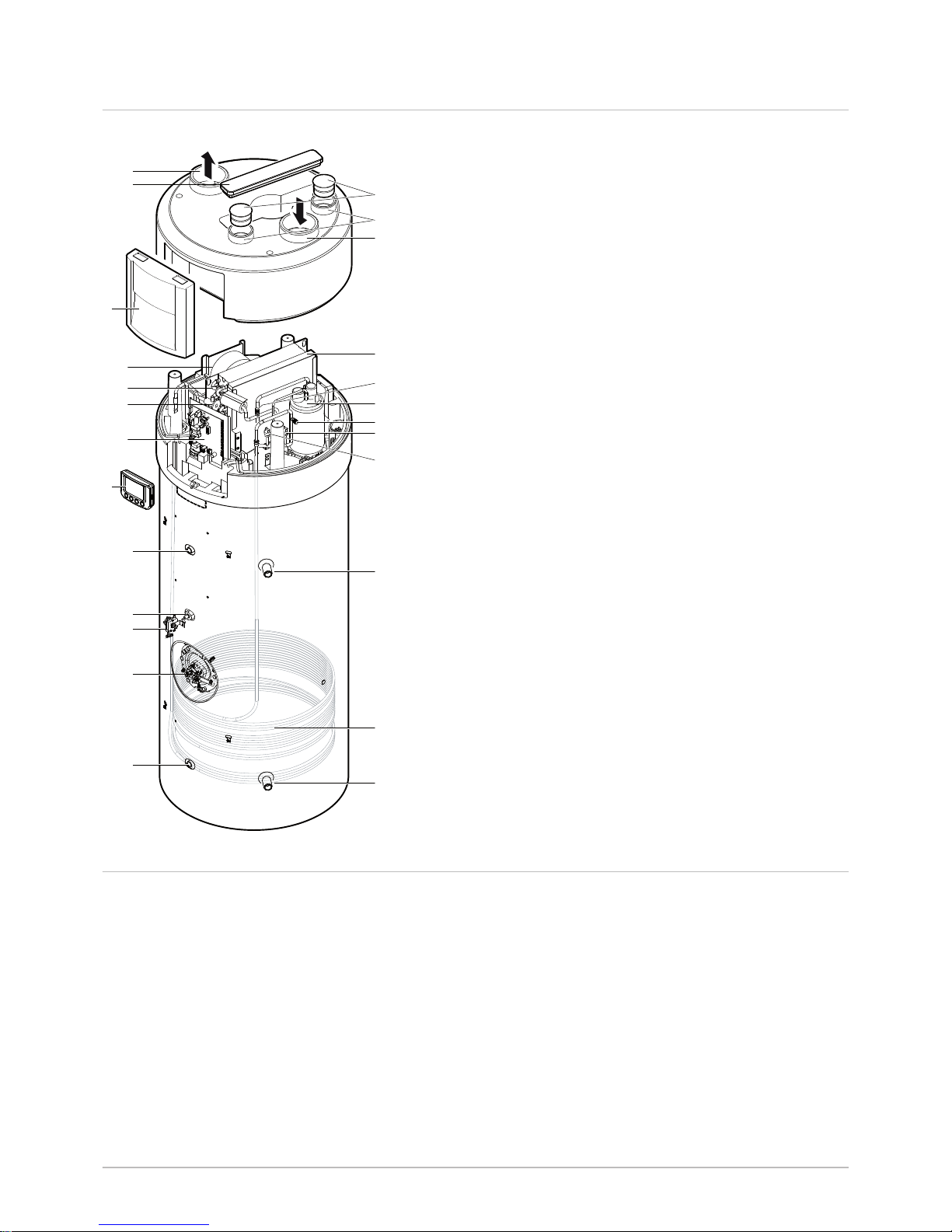
4.2 Main components
1 Air discharge connection, Ø160
2 Filter access hatch
3 Cover
4 Fan
5 Evaporator
6 Expansion valve
7 Control system
8 Control module
9 Housing for temperature sensor
10 Impressed current anode
11 Safety thermostat
12 Steatite immersion heater
13 Housing for temperature sensor
14 Cold water inlet
15 Condenser
16 Domestic hot water outlet
17 HP pressure switch
18 LP pressure switch
19 Pressure measurement point – High pressure (HP)
20 Compressor
21 Pressure measurement point – Low pressure (LP)
22 Air filter
23 Air intake connection, Ø160
24 Domestic air fitting, Ø80
25 Plug, Ø80
4.3
Operating principle
The thermodynamic water heater groups the domestic hot water tank and
controlled mechanical ventilation functions. The calories contained in the
air extracted from the building are used for the production of domestic hot
water.
The refrigerant circuit is a closed circuit in which the R-134a refrigerant
plays the role of an energy carrier.
The heat from the intake air is transferred to the refrigerant in the finned
heat exchanger at a low evaporation temperature.
The refrigerant is drawn in, in vapour form, by a compressor which raises it
to a higher pressure and temperature and sends it to the condenser. In the
condenser, the heat extracted in the evaporator and some of the energy
absorbed by the compressor are released into the water.
The refrigerant is depressurised in the thermostatic expansion valve and
then cooled. The refrigerant can again extract the heat contained in the
intake air from the evaporator.
Fig.1
M002826-G
9
13
14
15
16
23
22
20
8
17
18
21
19
10
11
12
5
4
6
7
1
2
3
25
24
4 Description of the product
16 TWH 200 EV EN-7602142 - v11 - 24042019
Page 17
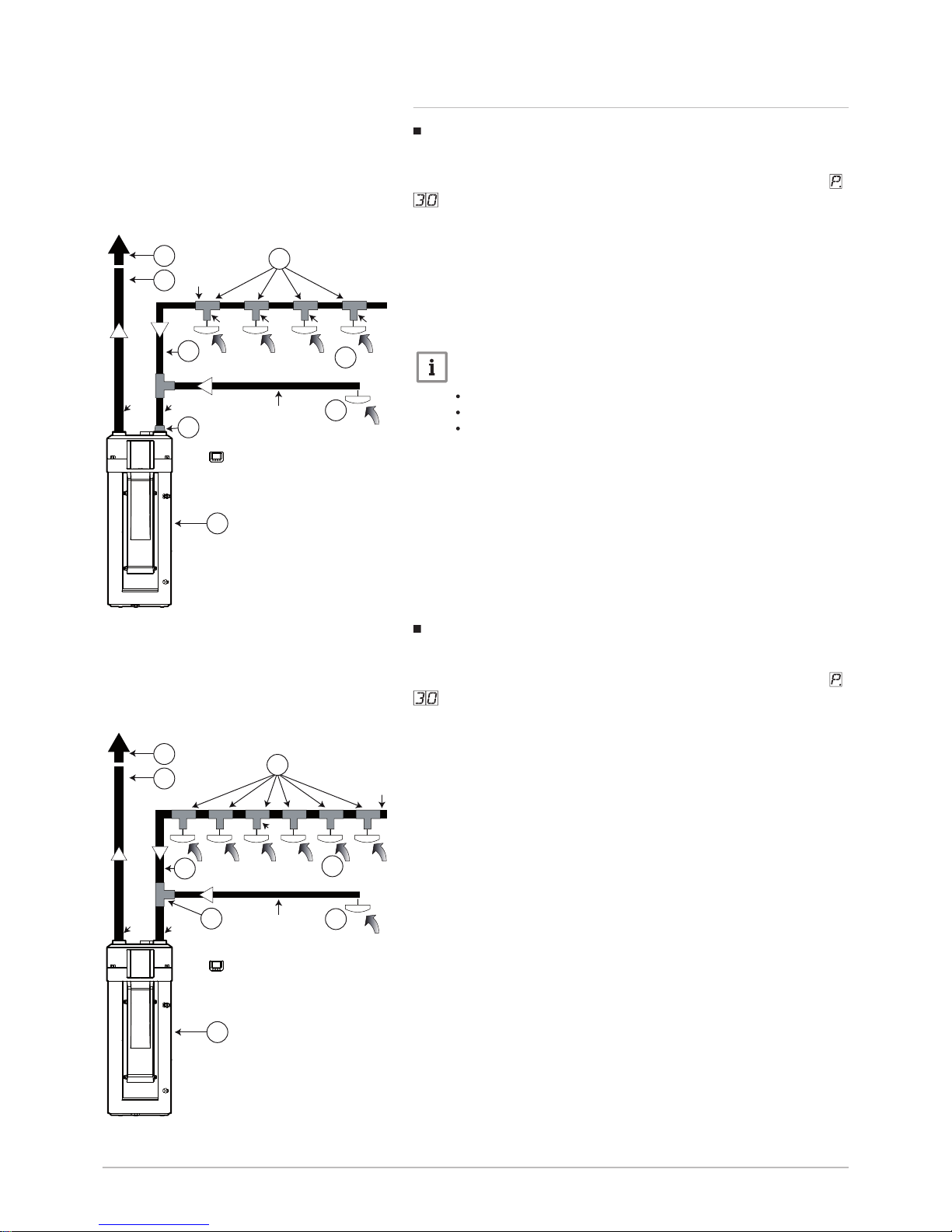
4.3.1 Linear network
Linear network with a maximum of four sanitary extractor fan
outlets
In this configuration, the air duct vacuum pressure set point (parameter
) must be set to 1 (= 100 Pa).
1 Sanitary extractor fan outlets, Ø 80 mm (bathroom/WC)
2 Kitchen extractor fan outlet, Ø 125 mm
3 Thermodynamic water heater
4 Roof-mounted discharge
5 Duct (insulated if outside of the heated area)
6 125/80 Tee fitting
7 160 Tee fitting + 160/125 reduction sleeve
Important
This configuration may include a maximum of:
2 bathrooms
2 WCs
1 kitchen
Linear network with a maximum of 6 sanitary extractor fan
outlets
In this configuration, the air duct vacuum pressure set point (parameter
) must be set to 1 (= 100 Pa).
1 Sanitary extractor fan outlets, Ø 80 mm (bathroom/WC)
2 Kitchen extractor fan outlet, Ø 125 mm
3 Thermodynamic water heater
4 Roof-mounted discharge
5 Duct (insulated if outside of the heated area)
6 160/80 Tee fitting + 160/80 reduction sleeve
7 160/80 reduction sleeve
Fig.2
M002827-E
1
7
5
2
Ø125
Ø125
Ø160
Ø125
Ø80 Ø80 Ø80 Ø80
4
5
6
3
Fig.3
C004747-A
1
5
7
2
Ø125
Ø160
Ø160
Ø160
Ø80
4
5
3
6
4 Description of the product
EN-7602142 - v11 - 24042019 TWH 200 EV 17
Page 18
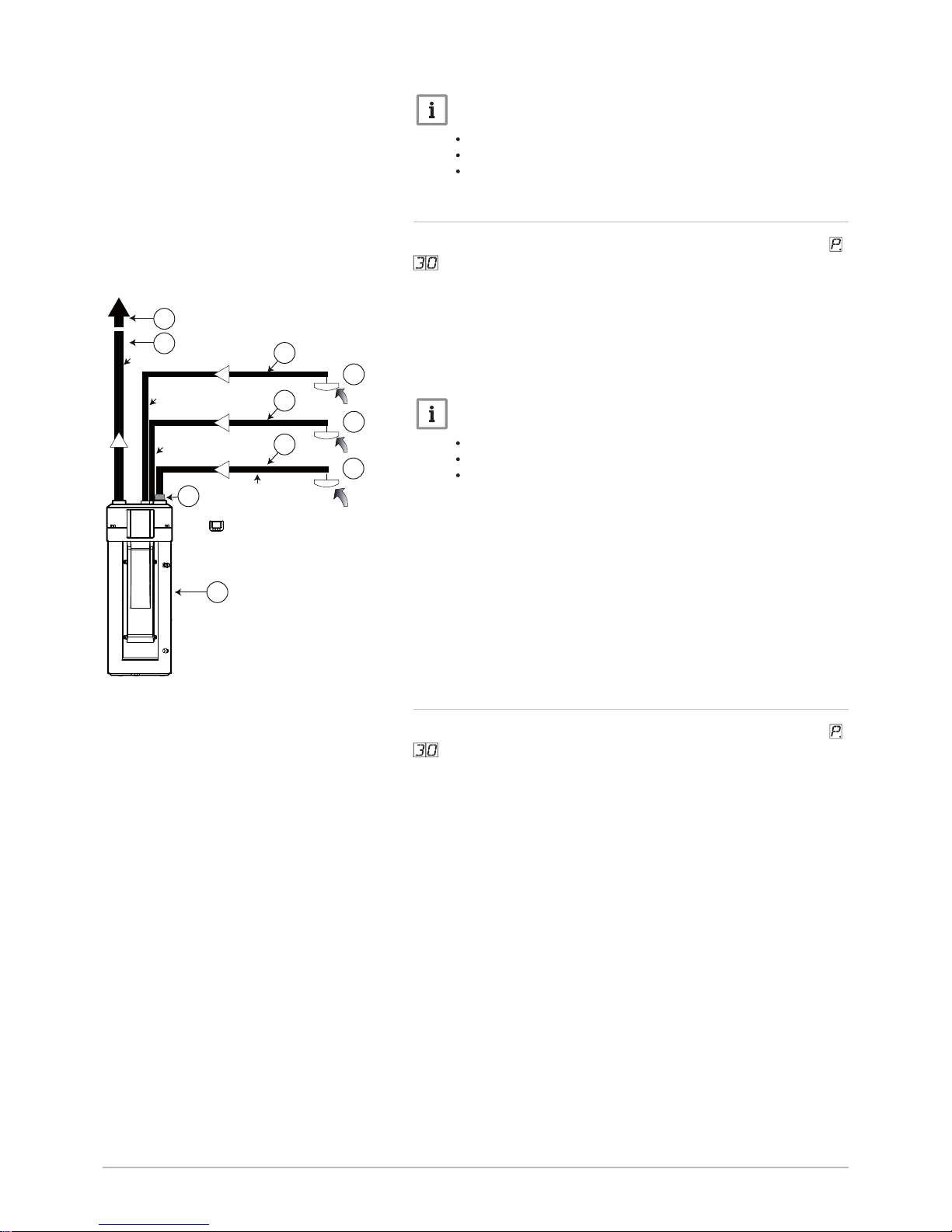
Important
This configuration may include a maximum of:
3 bathrooms
3 WCs
1 kitchen
4.3.2 Direct connection to the thermodynamic water heater
In this configuration, the air duct vacuum pressure set point (parameter
) must be set to 1 (= 100 Pa).
1 Sanitary extractor fan outlets, Ø 80 mm (bathroom / WC)
2 Kitchen extractor fan outlet, Ø 125 mm
3 Thermodynamic water heater
4 Roof-mounted discharge
5 Duct (insulated if outside of the heated area)
6 160/125 reduction sleeve
Important
This configuration may include a maximum of:
1 bathroom
1 WC
1 kitchen
4.3.3 Multi-duct network with collector
In this configuration, the air duct vacuum pressure set point (parameter
) must be set to 2 (= 125 Pa).
Fig.4
C004496-B
1
1
6
2
Ø125
Ø160
Ø80
Ø80
4
5
5
5
5
3
4 Description of the product
18 TWH 200 EV EN-7602142 - v11 - 24042019
Page 19
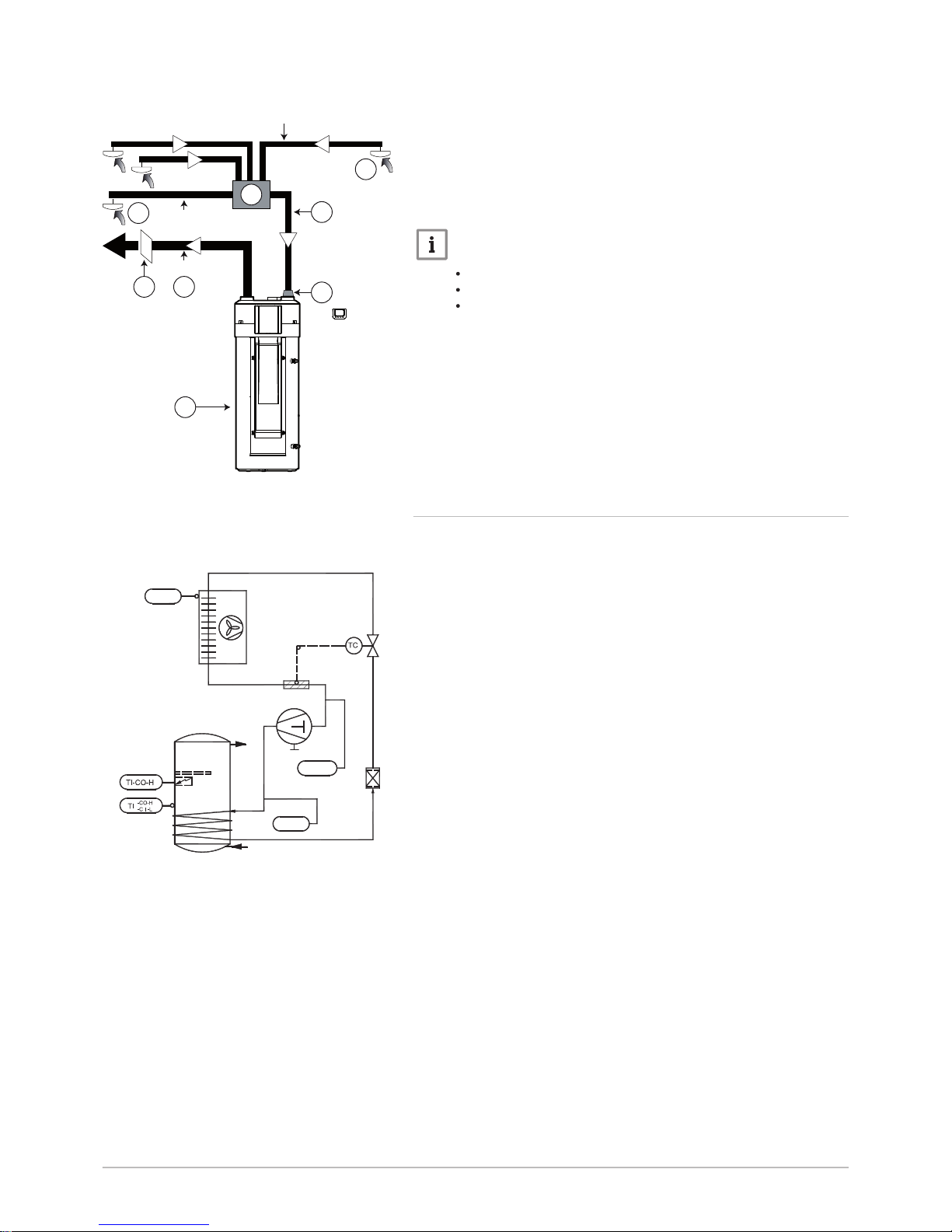
1 Sanitary extractor fan outlets, Ø 80 mm (bathroom/WC)
2 Kitchen extractor fan outlet, Ø 125 mm
3 Thermodynamic water heater
4 Duct (insulated if outside of the heated area)
5 Wall-mounted discharge
6 Collector
7 160 Tee fitting + 160/125 reduction sleeve
Important
This configuration may include a maximum of:
3 bathrooms
3 WCs
1 kitchen
4.3.4 Schematic diagram
1 Compressor
2 LP pressure switch
3 Condenser
4 Domestic hot water tank
5 Steatite immersion heater
6 Impressed current anode
7 Temperature controller (heat pump)
8 Safety thermostat (immersion heater)
9 Filter-drier
10 Thermostatic expansion valve
11 HP pressure switch
12 Ambient air sensor
13 Evaporator with air filter
14 Expansion valve bulb
Fig.5
M002828-E
1
2
3
4
7
Ø80
6
Ø125
Ø160
45
Fig.6
M002829-C
11
2
1
14
13
12
4
5
6
8
7
3
9
10
4 Description of the product
EN-7602142 - v11 - 24042019 TWH 200 EV 19
Page 20
5 Installation
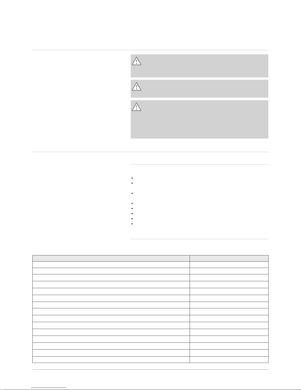
5.1 Installation regulations
Caution
The appliance must be installed and maintained by a certified
professional in accordance with prevailing statutory texts and
codes of practice.
Caution
Install the thermodynamic water heater in a dry, frost-free location
which is within the thermal envelope of the home.
Caution
Attach the CMV network ducts to the water heater using adhesive
tape or a clamp, ensuring compliance with the requirements of
standard 60 335-1 article 22.111 relating to the strength of this
assembly. Ensure that there are no gaps in the sealing, as this will
prevent issues including excess energy consumption, poor
ventilation in the home, or a lack of domestic hot water.
5.2
Package list
5.2.1 Standard delivery
The delivery includes:
The thermodynamic water heater
The control system display, not fitted so it can be installed in the desired
room
A dielectric union (supplied in the documentation bag for the water
heater)
A condensates discharge hose
One screw bag
A refrigerant sticker with its manual
The Installation and Service Manual
The User Guide
5.2.2 Accessories
Tab.3
Accessories Package
Gripping kit ER239
Trim for fitting the control module on the appliance EH290
Battery-powered humidity-controlled extractor fan for kitchens 10/40/90 m3/h
EH703
Battery-powered humidity-controlled extractor fan for kitchens 10/45/135 m3/h
EH293
Humidity-controlled extractor fan with pull-cord for kitchens 10/40/90 m3/h
EH707
Humidity-controlled extractor fan with pull-cord for kitchens 10/45/135 m3/h
EH297
Battery-powered humidity-controlled extractor fan for bathrooms 5/40 m3/h EH299
Humidity-controlled extractor fan for bathrooms 5/40/30 m3/h
EH882
Humidity-controlled extractor fan for bathrooms 15/45/40 m3/h
EH883
Battery-powered humidity-controlled extractor fan for bathrooms 10/45 m3/h
EH302
Battery-powered humidity-controlled extractor fan for bathrooms 15/45/45 m3/h
EH712
Battery-powered humidity-controlled extractor fan for bathrooms 10/40 m3/h
EH301
Battery-powered humidity-controlled extractor fan for WC 5/30 m3/h
EH303
Humidity-controlled air intake kit 5/45 m3/h
EH715
Plastic sleeve, Ø 125 for extractor fan EH307
5 Installation
20 TWH 200 EV EN-7602142 - v11 - 24042019
Page 21
Accessories Package
Roof cowl, Ø 160 (tile colour) EH309
Roof cowl, Ø 160 (slate colour) EH370
Wall duct with grille, Ø 160 EH208
External grille, Ø 160 (aluminium) EH209
Flexible insulated duct, Ø 80 (insulation thickness 50 mm and length 6 m) EH312
Flexible insulated duct, Ø 125 (insulation thickness 50 mm and length 6 m) EH313
Flexible insulated duct, Ø 160 (insulation thickness 50 mm and length 6 m) EH314
Collector unit with 6 x Ø 80 connections and 2 x Ø 125 connections EH315
PPE duct, Ø 125, length 2x1 m + sleeve (2x) EH317
PPE duct, Ø 160, length 2x1 m + sleeve (2x) EH272
90° elbow (PPE) Ø 160 (2x) + sleeve (2x) EH273
90° elbow (PPE) Ø 125 (2x) + sleeve (2x) EH319
PPE sleeve, Ø 160 (2x) EH274
PPE sleeve, Ø 125 (2x) EH321
Galvanised straight Tee fitting, 90°, Ø 125 EH322
Galvanised straight Tee fitting, 90°, Ø 160 EH323
Galvanised straight Tee fitting, 90°, Ø 125x80 EH324
Galvanised straight Tee fitting, 90°, Ø 160x125 EH325
Galvanised reduction, Ø 125x80 EH326
Galvanised reduction, Ø 160x80 EH327
Galvanised reduction, Ø 160x125 EH328
Galvanised sleeve, Ø 125 EH329
Galvanised sleeve, Ø 160 EH330
Set of 10 clamps, Ø 80 - Ø 125 EH331
Set of 2 clamps, Ø 160 EH207
Filter EH334
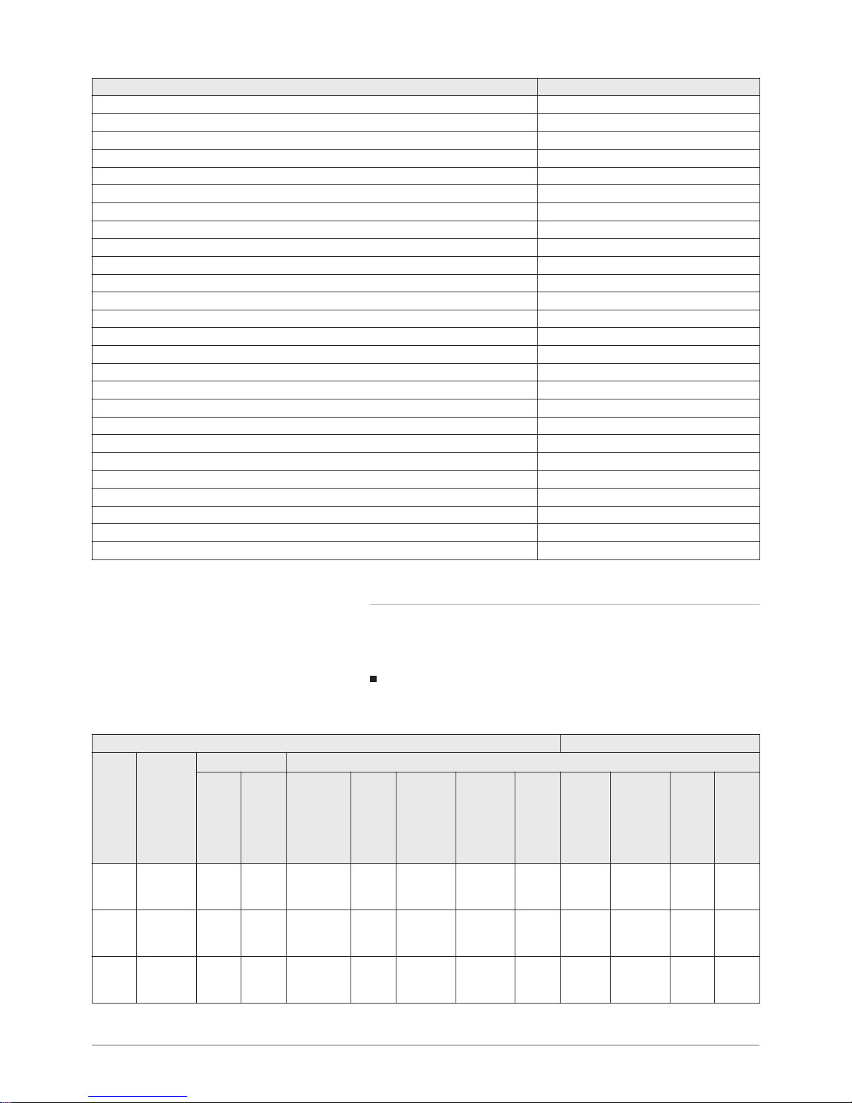
5.2.3 System configuration
The system configuration must comply with the Technical Specification
14.5/17-2285_V1 and its commercial extension 14.5/17-2285_V1-E1.
For more details, consult the Technical Specification.
Sizing a type A humidity-controlled VMC
Tab.4
Basic configuration Additional technical components
Type
of
home
Humid
rooms
Air inlet module
Extractor fans: flow rate (m3/h) / package no.
Living
room
Flow
rate
(m
3
/h)
Per
bed
room
Flow
rate
(m
3
/h)
Kitchen Bath
room
BthRm /
WC1
Bath
room /
WC2
WC Other
bath
room
Other
bath
room /
WC
Other WCWash
room
Studio
flat
1 bath
room/WC
2x45 – 10/40/90
EH707 or
EH703
– 15/45/45
EH712
- - 5/40
EH299
15/45/45
EH712
– 5/40
EH299
Studio
flat
1 bath
room/WC
2x45 – 10/40/90
EH707 or
EH703
– 15/45/45
EH712
- - - 15/45/45
EH712
5/30
EH303
5/40
EH299
Studio
flat
1 bath
room +
1 WC
2x45 – 10/40/90
EH707 or
EH703
10/40
EH301
- - 5/30
EH303
10/40
EH301
5/40/30
EH882
5/30
EH303
5/40
EH299
5 Installation
EN-7602142 - v11 - 24042019 TWH 200 EV 21
Page 22

Basic configuration Additional technical components
Type
of
home
Humid
rooms
Air inlet module
Extractor fans: flow rate (m3/h) / package no.
Living
room
Flow
rate
(m3/h)
Per
bed
room
Flow
rate
(m3/h)
Kitchen Bath
room
BthRm /
WC1
Bath
room /
WC2
WC Other
bath
room
Other
bath
room /
WC
Other WCWash
room
1-bed
flat
1 bath
room/WC
2x30 30 10/40/90
EH707 or
EH703
– 15/45/40
EH883
- - 5/40
EH299
15/45/45
EH712
– 5/40
EH299
1-bed
flat
1 bath
room/WC
2x30 30 10/40/90
EH707 or
EH703
– 15/45/40
EH883
- - - 15/45/45
EH712
5/30
EH303
5/40
EH299
1-bed
flat
1 bath
room +
1 WC
2x30 30 10/40/90
EH707 or
EH703
10/45
EH302
- - 5/30
EH303
10/45
EH302
5/40/30
EH882
5/30
EH303
5/40
EH299
2-bed
flat
1 bath
room/WC
2x30 30 10/45/135
EH297 or
EH293
– 15/45/40
EH883
- - 5/40
EH299
15/45/45
EH712
– 5/40
EH299
2-bed
flat
1 bath
room/WC
2x30 30 10/45/135
EH297 or
EH293
– 15/45/40
EH883
- - - 15/45/45
EH712
5/30
EH303
5/40
EH299
2-bed
flat
1 bath
room +
1 WC
2x30 30 10/45/135
EH297 or
EH293
10/45
EH302
- - 5/30
EH303
10/45
EH302
5/40/30
EH882
5/30
EH303
5/40
EH299
3-bed
flat
1 bath
room/WC
45 30 10/45/135
EH297 or
EH293
– 15/45/40
EH883
- - 5/40
EH299
15/45/45
EH712
– 5/40
EH299
3-bed
flat
1 bath
room/WC
45 30 10/45/135
EH297 or
EH293
– 15/45/40
EH883
- - - 15/45/45
EH712
5/30
EH303
5/40
EH299
3-bed
flat
1 bath
room +
1 WC
45 30 10/45/135
EH297 or
EH293
10/45
EH302
- - 5/30
EH303
10/45
EH302
5/40/30
EH882
5/30
EH303
5/40
EH299
4-bed
flat
1 bath
room/WC
45 30 10/45/135
EH297 or
EH293
– 15/45/40
EH883
- - 5/40
EH299
15/45/45
EH712
– 5/40
EH299
4-bed
flat
1 bath
room/WC
45 30 10/45/135
EH297 or
EH293
– 15/45/40
EH883
- - - 15/45/45
EH712
5/30
EH303
5/40
EH299
4-bed
flat
1 bath
room +
1 WC
45 30 10/45/135
EH297 or
EH293
10/45
EH302
- - 5/30
EH303
10/45
EH302
5/40/30
EH882
5/30
EH303
5/40
EH299
5-bed
flat
2 bath
rooms/W
C
45 30 10/45/135
EH297 or
EH293
– 15/45/40
EH883
15/45/40
EH883
– 5/40
EH299
15/45/45
EH712
– 5/40
EH299
5-bed
flat
2 bath
rooms/W
C
45 30 10/45/135
EH297 or
EH293
– 15/45/40
EH883
15/45/40
EH883
- - 15/45/45
EH712
5/30
EH303
5/40
EH299
5-bed
flat
1 bath
room/WC
1 bath
room +
1 WC
45 30 10/45/135
EH297 or
EH293
10/45
EH302
15/45/40
EH883
– 5/30
EH303
– 15/45/45
EH712
5/30
EH303
5/40
EH299
6-bed
flat
2 bath
rooms/W
C
45 30 10/45/135
EH297 or
EH293
– 15/45/40
EH883
15/45/40
EH883
– 5/40
EH299
15/45/45
EH712
– 5/40
EH299
5 Installation
22 TWH 200 EV EN-7602142 - v11 - 24042019
Page 23
Basic configuration Additional technical components
Type
of
home
Humid
rooms
Air inlet module
Extractor fans: flow rate (m3/h) / package no.
Living
room
Flow
rate
(m3/h)
Per
bed
room
Flow
rate
(m3/h)
Kitchen Bath
room
BthRm /
WC1
Bath
room /
WC2
WC Other
bath
room
Other
bath
room /
WC
Other WCWash
room
6-bed
flat
2 bath
rooms/W
C
45 30 10/45/135
EH297 or
EH293
– 15/45/40
EH883
15/45/40
EH883
- - 15/45/45
EH712
5/30
EH303
5/40
EH299
6-bed
flat
1 bath
room/WC
1 bath
room +
1 WC
45 30 10/45/135
EH297 or
EH293
10/45
EH302
15/45/40
EH883
– 5/30
EH303
– 15/45/45
EH712
5/30
EH303
5/40
EH299
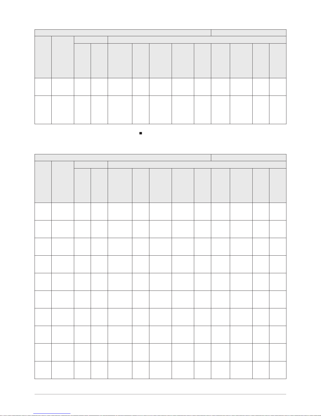
Sizing a type B humidity-controlled VMC
Tab.5
Basic configuration Additional technical components
Type
of
home
Humid
rooms
Air inlet module
Extractor fans: flow rate (m3/h) / package no.
Living
room
Flow
rate
(m
3
/h)
Per
bed
room
Flow
rate
(m
3
/h)
Kitchen Bath
room
BthRm /
WC1
Bath
room /
WC2
WC Other
bath
room
Other
bath
room /
WC
Other WCWash
room
Studio
flat
1 bath
room/WC
2x5/45
EH715
or 45
– 10/40/90
EH707 or
EH703
– 15/45/45
EH712
- - 5/40
EH299
15/45/45
EH712
– 5/40
EH299
Studio
flat
1 bath
room/WC
2x5/45
EH715
or 45
– 10/40/90
EH707 or
EH703
– 15/45/45
EH712
- - - 15/45/45
EH712
5/30
EH303
5/40
EH299
Studio
flat
1 bath
room +
1 WC
2x5/45
EH715
or 45
– 10/40/90
EH707 or
EH703
10/40
EH301
- - 5/30
EH303
10/40
EH301
5/40/30
EH882
5/30
EH303
5/40
EH299
1-bed
flat
1 bath
room/WC
5/45
EH715
5/45
EH715
10/40/90
EH707 or
EH703
– 15/45/45
EH712
- - 5/40
EH299
15/45/45
EH712
– 5/40
EH299
1-bed
flat
1 bath
room/WC
5/45
EH715
5/45
EH715
10/40/90
EH707 or
EH703
– 15/45/45
EH712
- - - 15/45/45
EH712
5/30
EH303
5/40
EH299
1-bed
flat
1 bath
room +
1 WC
5/45
EH715
5/45
EH715
10/40/90
EH707 or
EH703
10/40
EH301
- - 5/30
EH303
10/40
EH301
5/40/30
EH882
5/30
EH303
5/40
EH299
2-bed
flat
1 bath
room/WC
5/45
EH715
5/45
EH715
10/45/135
EH297 or
EH293
– 15/45/45
EH712
- - 5/40
EH299
15/45/45
EH712
– 5/40
EH299
2-bed
flat
1 bath
room/WC
5/45
EH715
5/45
EH715
10/45/135
EH297 or
EH293
– 15/45/45
EH712
- - - 15/45/45
EH712
5/30
EH303
5/40
EH299
2-bed
flat
1 bath
room +
1 WC
5/45
EH715
5/45
EH715
10/45/135
EH297 or
EH293
10/40
EH301
- - 5/30
EH303
10/40
EH301
5/40/30
EH882
5/30
EH303
5/40
EH299
3-bed
flat
1 bath
room/WC
5/45
EH715
5/45
EH715
10/45/135
EH297 or
EH293
– 15/45/45
EH712
- - 5/40
EH299
15/45/45
EH712
– 5/40
EH299
5 Installation
EN-7602142 - v11 - 24042019 TWH 200 EV 23
Page 24

Basic configuration Additional technical components
Type
of
home
Humid
rooms
Air inlet module
Extractor fans: flow rate (m3/h) / package no.
Living
room
Flow
rate
(m3/h)
Per
bed
room
Flow
rate
(m3/h)
Kitchen Bath
room
BthRm /
WC1
Bath
room /
WC2
WC Other
bath
room
Other
bath
room /
WC
Other WCWash
room
3-bed
flat
1 bath
room/WC
5/45
EH715
5/45
EH715
10/45/135
EH297 or
EH293
– 15/45/45
EH712
- - - 15/45/45
EH712
5/30
EH303
5/40
EH299
3-bed
flat
1 bath
room +
1 WC
5/45
EH715
5/45
EH715
10/45/135
EH297 or
EH293
10/40
EH301
- - 5/30
EH303
10/40
EH301
5/40/30
EH882
5/30
EH303
5/40
EH299
4-bed
flat
1 bath
room/WC
5/45
EH715
5/45
EH715
10/45/135
EH297 or
EH293
– 15/45/45
EH712
- - 5/40
EH299
15/45/45
EH712
– 5/40
EH299
4-bed
flat
1 bath
room/WC
5/45
EH715
5/45
EH715
10/45/135
EH297 or
EH293
– 15/45/45
EH712
- - - 15/45/45
EH712
5/30
EH303
5/40
EH299
4-bed
flat
1 bath
room +
1 WC
5/45
EH715
5/45
EH715
10/45/135
EH297 or
EH293
10/40
EH301
- - 5/30
EH303
10/40
EH301
5/40/30
EH882
5/30
EH303
5/40
EH299
5-bed
flat
2 bath
rooms/W
C
5/45
EH715
5/45
EH715
10/45/135
EH297 or
EH293
– 15/45/45
EH712
15/45/40
EH883
– 5/40
EH299
15/45/45
EH712
– 5/40
EH299
5-bed
flat
2 bath
rooms/W
C
5/45
EH715
5/45
EH715
10/45/135
EH297 or
EH293
– 15/45/45
EH712
15/45/40
EH883
- - 15/45/45
EH712
5/30
EH303
5/40
EH299
5-bed
flat
1 bath
room/WC
1 bath
room +
1 WC
5/45
EH715
5/45
EH715
10/45/135
EH297 or
EH293
10/40
EH301
15/45/40
EH883
– 5/30
EH303
– 15/45/45
EH712
5/30
EH303
5/40
EH299
6-bed
flat
2 bath
rooms/W
C
5/45
EH715
5/45
EH715
10/45/135
EH297 or
EH293
– 15/45/45
EH712
15/45/40
EH883
– 5/40
EH299
15/45/45
EH712
– 5/40
EH299
6-bed
flat
2 bath
rooms/W
C
5/45
EH715
5/45
EH715
10/45/135
EH297 or
EH293
– 15/45/45
EH712
15/45/40
EH883
- - 15/45/45
EH712
5/30
EH303
5/40
EH299
6-bed
flat
1 bath
room/WC
1 bath
room +
1 WC
5/45
EH715
5/45
EH715
10/45/135
EH297 or
EH293
10/40
EH301
15/45/40
EH883
– 5/30
EH303
– 15/45/45
EH712
5/30
EH303
5/40
EH299
5 Installation
24 TWH 200 EV EN-7602142 - v11 - 24042019
Page 25

5.3 Storing and transporting the appliance
Caution
Have 2 people available.
Use a 3-wheel hand truck.
Handle the appliance with gloves.
The appliance cover cannot be used for transport operations.
The cover is not capable of withstanding heavy weights.
Ensure the room height is a minimum of approximately 2.10 m.
Important
To facilitate handling of the appliance and prevent damage, it is
recommended that the ER239 gripper kit is used.
The thermodynamic water heater must be stored and transported in its
packaging and not filled with water.
Permissible ambient transport and storage temperatures: -15 to +60°C.
5.3.1
Transport
Important
We recommend shipping the appliance vertically.
It is possible to transport the appliance horizontally over short distances
and only whilst resting on its rear panel.
5 Installation
EN-7602142 - v11 - 24042019 TWH 200 EV 25
Page 26

Caution
It is prohibited to stack or set down the appliance any of its other
sides, as this may lead to malfunctions or faults.
5.4
Choice of the location
5.4.1
Data plate
The data plate must be accessible at all times.
The data plate identifies the product and provides the following
information:
Appliance type
Date of manufacture (Year - Week)
Serial number
5.4.2
Position of the appliance
Caution
When installing the appliance, comply with the IP21 protection
rating.
Caution
Do not position the air intake in areas exposed to gas, vapours
or dust. Do not position the air intake in an atmosphere with
chlorine (swimming pool) or fluorine (aerosols, detergents,
solvents, etc.).
Temperature of the air extracted by the heat pump, for optimum
operation: approximately 20°C.
Important
Fig.7
MW-1000371-1
Fig.8
M002830-D
5 Installation
26 TWH 200 EV EN-7602142 - v11 - 24042019
Page 27

Recommended positions
Install the appliance in a dry, frost-free room at a minimum temperature
of 7 °C (optimum temperature: 20 °C).
Install the appliance on a flat, solid surface.
Install the appliance on a base frame. The base frame must be able to
support the load sufficiently at all times.
Free installation
1. Allow sufficient space around the appliance to allow access and
facilitate maintenance.
Installation in a cupboard
1. Provide a movable partition to allow access to the appliance and
facilitate maintenance operations.
Fig.9
=
=
650
min.
400
1675
min. 700
C004118-D
Fig.10
C004136-B
650
50°
Fig.11
C004137-B
650
700
50°
5 Installation
EN-7602142 - v11 - 24042019 TWH 200 EV 27
Page 28

5.4.3 Main dimensions
Fig.12
M002832-E
1675
1332
1069
249
667
50°
133°
1
2
3
(1)
o 632
o 160
o 160
o 80
o 80
346
360
266
154
18
147
1 Domestic hot water outlet G 3/4" – Dielectric union
fitted
2 Domestic cold water inlet G 3/4"
3 Condensates outlet
(1) Adjustable feet
For more information, see
Positioning the appliance, page 29
5 Installation
28 TWH 200 EV EN-7602142 - v11 - 24042019
Page 29

5.5 Positioning the appliance
5.5.1 Unpacking the appliance
Caution
Remove all packaging materials. Check that the contents are
intact. If you notice a defect, do not use the appliance and contact
the supplier.
1. Remove the 3 retaining screws.
2. Lift and remove the cover.
Warning
Lift the cover, ensuring it remains along the vertical axis. Risk of
damage to the insertion guides.
Fig.13
C004122-D
1
2
5 Installation
EN-7602142 - v11 - 24042019 TWH 200 EV 29
Page 30

3. Undo the 3 nuts placed on top of the compressor retaining
components and discard.
4. Remove the compressor retaining components and discard.
5. Remove the control system display from its transport housing.
6. Refit the cover.
Warning
Check that no foreign bodies have made their way inside the
cover.
7. Put the retaining screws in place.
Fig.14
3
4
M002965-B
Fig.15
6
5
7
M002966-B
5 Installation
30 TWH 200 EV EN-7602142 - v11 - 24042019
Page 31

5.5.2 Positioning the appliance
See
Instructions affixed to the appliance packaging
Caution
After positioning the appliance, wait 3 hours before
commissioning.
5.5.3
Levelling the appliance
1. Level the appliance using the adjustable feet.
(1)
Adjustable feet
Basic dimension: 4 mm
Possible adjustment: from 4 mm to 21 mm
5.6 Water connections
Caution
Before attaching the water connections, it is essential to flush the
circuits to remove any particles which risk causing damage to
certain components (safety valve, pumps, valves, etc.).
If flushing has to be done using an aggressive product, neutralise
the rinsing water before disposing of it in the waste water network.
Important
Using hoses which are too short or too rigid encourages the
transmission of vibrations and the production of noises.
5.6.1 Connecting the water heater to the domestic water circuit
When making the connection, it is imperative that the standards and
corresponding local directives be respected.
Fig.16
M002833-C
(1)
19
5 Installation
EN-7602142 - v11 - 24042019 TWH 200 EV 31
Page 32

Specific precautions
Caution
Do not connect the domestic hot water connection directly to
copper pipes in order to prevent galvanic couplings in iron/copper
(risk of corrosion).
It is compulsory to fit the domestic hot water connection with a
dielectric union (provided).
Safety valve or safety unit
Caution
Germany: In accordance with the safety regulations, a safety
unit calibrated to 0.6 MPa (6 bar) must be fitted on the domestic
cold water inlet on the domestic hot water tank.
Belgium: In accordance with the safety regulations, a safety unit
calibrated to 0.7 MPa (7 bar), and approved by Belgaqua, must
be fitted on the domestic cold water inlet on the domestic hot
water tank.
Other countries: In accordance with the safety regulations, a
safety unit calibrated to 0.7 MPa (7 bar) must be fitted on the
domestic cold water inlet on the domestic hot water tank.
We recommend NF-marked hydraulic diaphragm safety units.
Integrate the safety valve in the cold water circuit.
Install the safety valve close to the water heater in a place with easy
access.
Sizing
The diameter of the safety unit and its connection to the water heater must
be at least equal to the diameter of the domestic cold water inlet on the
water heater.
There must be no cut-off devices between the safety valve or unit and
the water heater.
The discharge pipe in the safety valve or unit must not be blocked.
To prevent the flow of water being hindered or obstructed in the event of a
pressure surge:
The discharge pipe from the safety unit must have a continuous and
sufficient gradient, and its cross section must be at least equal to the
cross section of the opening of the safety unit outlet (to prevent the flow
of water being hindered if the pressure is too high).
The cross section of the discharge pipe from the safety unit must be at
least equal to the cross section of the opening on the safety unit outlet
Pressure reducer
If the supply pressure exceeds 80% of the safety valve or unit calibration
(e.g.: 0.55 MPa/5.5 bar for a safety unit calibrated to 0.7 MPa/7 bar), a
pressure reducer must be located upstream of the appliance.
Install the pressure reducer downstream of the water meter in such a way
as to ensure the same pressure in all of the system's pipes.
Measures to take to prevent hot water flow return
Fit a non-return valve to the domestic cold water circuit.
5 Installation
32 TWH 200 EV EN-7602142 - v11 - 24042019
Page 33

5.6.2 Fitting the dielectric union
Important
The dielectric union and its gasket are provided in the
documentation bag.
1. Screw the dielectric union onto the domestic hot water outlet, inserting
the gasket.
5.7
Air duct connections
1. Ensure that the intake and outlet tubes are held in place with clamps.
2. If the ducts are routed outside of the heated area, they must be
insulated.
3. Check the tightness after assembly.
Caution
Do not route the intake and outlet ducts on top of the filter.
Fig.17
C004590-C
1
Fig.18
C004123-C
5 Installation
EN-7602142 - v11 - 24042019 TWH 200 EV 33
Page 34

5.8 Condensate discharge
1. Fit a siphon into the condensate discharge duct.
Caution
If no siphon is fitted, there is a risk of problems with the discharge
of condensates when the compressor is running.
2. Attach the run-off collector.
5.9
Fitting and connecting the control module
The regulator control module is not fitted on the water heater when
delivered, so that it can be installed in one of the living areas, to make it
easier to use.
This control module can be installed remotely with a wire or radio
connection, or integrated.
5.9.1 Radio connection (installation strongly recommended)
Fitting the control module
Warning
Choose a location which enables good radio reception.
See
To test the quality of the radio reception, see the section: “Radio
test menu”.
Important
The quality of the radio reception may be affected by the
construction materials used within the home (thickness of the
walls or floor tiles, types of materials used).
Placing a hand in front of the control module may affect the
reception.
Fig.19
M002834-E
1
min. 200
5 Installation
34 TWH 200 EV EN-7602142 - v11 - 24042019
Page 35

Fig.20
C004121-D
1
2
3
6
7
6
1,5V
1,5V
5
4
1. Drill 2 holes 6 mm in diameter.
2. Put the plugs in place.
3. Attached the wall bracket (washers + screws provided).
Important
The screws and plugs are supplied in the bag of hardware.
4. Remove the protective cover from the battery compartment (batteries
provided) at the back of the control module.
5. Remove the protective tab from the batteries and discard it.
6. Position the control system module.
7. The water heater and the control module will communicate.
Important
Type of batteries: AA – LR6 – 1,5 V
Do not use rechargeable batteries.
Do not discard used batteries in the dustbin. Take them to an
appropriate collection place.
Important
When powering on for the first time, the control module will
automatically pair with the water heater control system PCB.
For more information, see
Pairing the control module and the tank, page 48
5 Installation
EN-7602142 - v11 - 24042019 TWH 200 EV 35
Page 36

5.9.2 Wire connection
Fig.21
C004124-D
8
9
1
2
3
6
7
6
4
5
1. Drill 2 holes 6 mm in diameter.
2. Put the plugs in place.
3. Attached the wall bracket (washers + screws provided).
Important
The screws and plugs are supplied in the bag of hardware.
4. Remove the cover from the control panel on the front of the appliance:
insert a screwdriver into the opening located underneath the control
panel cover, pushing it in as far as it will go.
5. Pull the bottom of the cover forward to release it.
6. Remove the cover from the control panel on the front of the appliance.
7. Connect the 2 wires (not provided) on the water heater PCB.
8. Route the wire between the wall and the control module wall bracket.
5 Installation
36 TWH 200 EV EN-7602142 - v11 - 24042019
Page 37

9. Connect the wire to the back of the control module then clip the
control module into its bracket.
Important
Remove the batteries from the control module.
A Control module
B Water heater PCB
Important
Type of cable: H05VV-F 2x1.0 mm2 (for example)
5.9.3
Integration into the front panel of the water heater
(optional)
Fig.23
C004127-D
4
5
6
7
NEW
3
1
2
1. Remove the cover from the control panel on the front of the appliance:
insert a screwdriver into the opening located underneath the control
panel cover, pushing it in as far as it will go.
2. Pull the bottom of the cover forward to release it.
3. Dispose of the cover.
Fig.22
C004125-C
A
B
5 Installation
EN-7602142 - v11 - 24042019 TWH 200 EV 37
Page 38

4. Fit the control module onto the front panel supplied in the option
package (washers + screws provided).
Important
The screws and washers are supplied in the EH290 accessories
package.
5. Connect the 2 wires on the control panel side.
6. Clip the bracket onto the front of the water heater.
7. Clip the control module into its bracket.
Important
Remove the batteries from the control module.
5.10
Electrical connections
5.10.1
Recommendations
Warning
Only qualified professionals may carry out electrical
connections, always with the power off.
Do not connect the power supply directly to the HP/HC contact.
Earthing must comply with the NFC 15-100 standard.
Power the appliance via a circuit that includes a type D curve omnipolar 16
A circuit breaker with a contact opening distance of 3 mm or more.
The appliance is supplied with a power supply cable. If the power cable is
damaged, it must be replaced by the manufacturer, its after sales service
or persons with similar qualifications in order to prevent any danger.
Electrical power is supplied by means of a power cord (~230 V, 50 Hz)
and an electrical socket.
Separate the sensor cables from the 230 V cables.
5.10.2
Peak rate/off-peak rate electrical connection
1. Access the PCB:
Radio or wire-connected control
module
Remove the cover from the appli
ance's front panel
Integrated into the front panel of
the water heater
Unclip the control module and re
move its support from the appli
ance's front panel
5 Installation
38 TWH 200 EV EN-7602142 - v11 - 24042019
Page 39

2. Connect the electrical connection using a cable with a cross section of
1.5 mm2.
For more information, see
Fitting and connecting the control module, page 34
5.10.3
Connection with peak rate/off-peak rate signal connected
Connection with HP/HC relay via a shunt
Fig.25
M002835-C
A
A
B
C1 C2
538 kW/h
1
1
A1
A2
0
Auto
0
15 / 45 A
500 mA
TEST
16 A40 A 2 A
30
mA
L
N
X11-2 HP/H
X11-1 LINE
C
1 2
3 4 4
1 Counter
2 Connection circuit breaker
3 AC-type/30 mA differential switch
4 Circuit breaker
A
1.5 mm2 control
B
1.5 mm2 shunt
Set the parameter to 2.
Fig.24
X11
HC/HP
C004499-A
5 Installation
EN-7602142 - v11 - 24042019 TWH 200 EV 39
Page 40

The heat pump and the back-up are not authorised to operate at peak
rate.
Boost one-touch quick heating.
The 2 wires for the HP/HC signal must be connected to the terminal
block X11 on the water heater PCB.
For more information, see
List of parameters, page 52
Connection with direct peak rate/off-peak rate contact on the
counter
Fig.26
M002836-C
C1 C2
538 kW/h
1
0
15 / 45 A
500 mA
TEST
16 A40 A 2 A
30
mA
L
N
X11-2 HP/HC
X11-1 LINE
A
1 2
3 4 4
1 Counter
2 Connection circuit breaker
3 AC-type/30 mA differential switch
4 Circuit breaker
A
1.5 mm2 control
Set the parameter to 2.
The heat pump and the back-up are not authorised to operate at peak
rate.
Boost one-touch quick heating.
The 2 wires for the peak rate/off-peak rate signal must be connected to
the terminal block X11 on the water heater PCB.
For more information, see
List of parameters, page 52
5 Installation
40 TWH 200 EV EN-7602142 - v11 - 24042019
Page 41

5.10.4 Connection with timer programming
Fig.27
M002837-C
C1 C2
538 kW/h
1
0
15 / 45 A
500 mA
TEST
16 A40 A 2 A
30
mA
L
N
1 2
3 4 4
1 Counter
2 Connection circuit breaker
3 AC-type/30 mA differential switch
4 Circuit breaker
Easy to install.
Opt for timer programming to benefit from the peak rate/off-peak rate
tariff.
5 Installation
EN-7602142 - v11 - 24042019 TWH 200 EV 41
Page 42

5.10.5 Connection with timer programming and photovoltaic
signal
Fig.28
C004822-B
A
TEST
16 A40 A 2 A
30
mA
L
N
X11-2 HP/H
PV-S
DC AC
X11-1 LINE
C
3
5
6
4 4
3 AC-type differential switch
4 Circuit breaker
5 Photovoltaic panel
6 Reversible
A
1.5 mm2 voltage cable
1. The heat pump and the electrical back-up are authorised to operate
according to the timer programming.
2. When the photovoltaic signal is active, the tank set point is 62 °C, and
can be adjusted via the parameter.
3. If the photovoltaic signal is active when the contact is open, set the
parameter to 3.
4. If the photovoltaic signal is active when the contact is closed, set the
parameter to 4.
5 Installation
42 TWH 200 EV EN-7602142 - v11 - 24042019
Page 43

5.11 Schematic wiring diagram
Fig.29
X1
Impressed current anode
X2
Bottom domestic hot water temperature sensor
X3
Middle domestic hot water temperature sensor
X4
Top domestic hot water temperature sensor
X5
Room temperature sensor, LP pressure switch
X6
Fan control
X7
Air pressure sensor
X10
Electrical back-up, Compressor, Condenser, Fan
X11
Off-peak rate contact
X14
Control module
LP
Low pressure
HP
High pressure
Earth
L
Live
N
Neutral
5 Installation
EN-7602142 - v11 - 24042019 TWH 200 EV 43
Page 44

5.12 Filling the thermodynamic water heater
1. Turn on a hot water tap.
A Domestic cold water inlet
2. Open the cold water tap located on the safety unit. Ensure that the
drain valve on the unit is properly closed.
3. When the water flows out from the hot water tap, the appliance is full.
Close the hot water tap.
Fig.30
M002838-F
A
5 Installation
44 TWH 200 EV EN-7602142 - v11 - 24042019
Page 45

6 Commissioning
6.1 Control panel description
6.1.1 Description of the keys
–
Browse keys
MODE Selection key for the operating modes
MENU Access key for the various menus
6.1.2 Description of the display
Available quantity of domestic hot water (according to the
set point)
Setting the parameters
! Alarm
Fan ON
(( )) Radio transmission activated
Programming or timer program currently active
:
Display of the date (day:month) or the time (hour:minutes)
1 2 3 4 5 6 7 Display of the day of the week (1 = Monday, 2 =
Tuesday, ... 7 = Sunday)
Numeric display
Number of baths available (40°C)
ltrs Quantity of water (litres)
°C Unit of temperature
kWh Consumed energy unit
Decreases the setting values
Increases the setting values
Confirm key
reset Resets the control system after a fault
Resets the default values to zero
Solar pump activated (depending on the configuration)
Automatic mode or Comfort mode
Eco mode
Boost mode
days
Holiday mode
Domestic hot water production mode indicator
The main display indicates the domestic hot water production mode.
Fig.31
C003197-B
MENUMODE
Fig.32
1
2
3
4
5
6
7
1
4
3
4
1
2
MW-C003186-2
6 Commissioning
EN-7602142 - v11 - 24042019 TWH 200 EV 45
Page 46

Tab.6
Display Domestic hot water pro
duction
Description
MW-C003487-03
Heat pump The 2 sections of the tank flash simultaneously when domestic hot water produc
tion is provided by the heat pump
MW-C003484-03
Electrical back-up The right-hand section of the tank flashes when domestic hot water production is
provided by the electrical back-up
MW-C003486-03
Heat pump + Electrical
back-up
The 2 sections of the tank flash in turn when domestic hot water production is
provided by the heat pump and the electrical back-up
Indicator for the available volume of water
During production of domestic hot water, the display indicates the number
of baths available and the filling level for the tank (available quantity of hot
water).
The number of baths is calculated based on a domestic hot water
temperature of 40°C.
The tank is filled based on the set point temperature.
Set the parameter according to the volume of water required for a
bath.
For more information, see
Modifying the installer parameters, page 51
6.1.3 Browsing in the menus
1. Press the MENU key once.
The SEtP 1 menu is displayed (Temperature measurement).
2. Use the and keys to scroll through the menus (see table
below).
3. To go into the selected menu, press the MODE key ( ).
4. To return to the previous display, press the MENU key.
Fig.33
C003493-B
1
4
3
4
1
2
Fig.34
C003203-E
1x
3
1
4
3
4
1
2
MENUMODE
Fig.35
M002843-B
1
4
3
4
1
2
MENUMODE
6 Commissioning
46 TWH 200 EV EN-7602142 - v11 - 24042019
Page 47

5. To return to the main display, press the MENU key once.
Tab.7
Accessing
the menu
Menu Description See
1x MENU SEtP 1 Setting the required number of water heater
baths
User Guide
1x SE nS 2 Measurements menu Measurements menu section
2x CL OC 3 Setting the time and date User Guide
3x Pr oG 4 Modifying a timer program User Guide
4x Co un 5 Counters Counters section
5x PA rA 6 Setting parameters User Guide
6x Er bL 7 Error history Log of messages and faults section
7x Co dE 8 Installer parameters Section on Modifying the installer parameters
8x SErV 9 Servicing the filter Section on Cleaning and replacing the filter
9x TSHF 10 Radio range test
This menu is only available in Radio mode
Radio test menu section
6.2 Points to check before commissioning
1. Check that the thermodynamic water heater is full of water.
2. Check the tightness of the connections.
3. Check that the safety devices are working correctly.
4. Check the operating mode.
6.3
Commissioning the appliance
6.3.1 Initial commissioning
Caution
Initial commissioning must be performed by a qualified
professional.
Carry out the commissioning operations in the following order:
1. Connect to the mains.
2. Check that no error codes or messages are shown on the display.
Important
When powering on for the first time, the control module will
automatically pair with the water heater control system PCB.
Important
The domestic hot water temperature set point is factory-set to
55°C in comfort mode.
3. Select the Boost operating mode.
4. The compressor and the back-up start to produce domestic hot water
if there is a domestic hot water production request.
For more information, see
Pairing the control module and the tank, page 48
Selecting the operating mode, page 49
6 Commissioning
EN-7602142 - v11 - 24042019 TWH 200 EV 47
Page 48

6.3.2 Pairing the control module and the tank
Important
Only affects appliances with a control module which has been
installed in radio mode.
Powering on for the first time
Important
When powering on for the first time, the control module will
automatically pair with the water heater control system PCB.
If there are any issues when pairing, perform a forced pairing procedure.
See
Forcing pairing from the control module section.
Forcing pairing from the control module
1. Simultaneously press the and MODE keys.
The Pair SEt menu is displayed.
2. Press the MODE key to confirm to start pairing.
3. If pairing is successful, the control module displays InIt.
Forcing manual pairing
1. Remove the batteries from the control module.
2. Connect the control module with a wire to the tank control system
PCB.
3. Switch on the power to the tank.
4.
Press the key for 5 seconds.
The rSt HMi menu is displayed.
5. Press the MODE ( ) key.
6. Switch off the power to the tank.
7. Perform the radio connection procedure for the control module.
For more information, see
Wire connection, page 36
6.4
Checks and settings after commissioning
1. Check the tightness of the connections.
2. Check the temperature on the 3 domestic hot water temperature
sensors to ensure that the appliance is working correctly.
If the readout values are incorrect, check the positioning of the
sensors in the sensor tube.
Fig.36
C004779-B
1
4
3
4
1
2
MENUMODE
Fig.37
C004780-B
1
4
3
4
1
2
MENUMODE
Fig.38
C004781-B
1
4
3
4
1
2
MENUMODE
6 Commissioning
48 TWH 200 EV EN-7602142 - v11 - 24042019
Page 49

3. A few days after commissioning of the appliance, a visual inspection
must be performed to check for any leaks in the water system or any
blockages in the condensate run-off.
4. Check the pressure at the extractor fans (see table below).
Tab.8
Hygro-adjustable Self-adjusting
At the minimum
flow rate
Check that the pressure at the extractor fans is be
tween 80 and 160 Pa using a pressure gauge.
Check that the pressure at the extractor fans is be
tween 50 and 160 Pa using a pressure gauge.
At the maximum
flow rate
Activate the kitchen high flow rate.
Check that the pressure at the kitchen extractor fan
is greater than 70 Pa.
Activate the kitchen high flow rate.
Check that the pressure at the kitchen extractor fan
is greater than 70 Pa.
6.5
Selecting the operating mode
The operating mode is indicated on the main display.
1. To change the operating mode, press the MODE key several times,
until the symbol corresponding to the required operating mode is
shown on the display.
Important
During peak rate, or outside of the programmed timer ranges, the
compressor may start up to ensure the production of domestic hot
water.
Tab.9
Display Operating mode Description
Automatic or comfort Comfort program active
The production of domestic hot water is ensured by the heat pump and, if neces
sary, by the electrical back-up.
If the production of domestic hot water is not fulfilled by the end of the specified
period, the back-up starts up automatically.
Eco Reduced program active
The production of domestic hot water is ensured by the heat pump only.
After the compressor stops, the display showing the available quantity of domes
tic hot water may not be full ( ).
Boost Forced operation active
The production of domestic hot water is ensured by the heat pump and the backup simultaneously for a defined period (factory setting: 6 hours).
days Holiday Holiday period:
Production of domestic hot water is stopped.
The domestic hot water temperature is maintained at 10°C (for a maximum of 99
days).
6.6
Reading out measured values
6.6.1
Measurements menu
1. Press the MENU key once.
The SEtP 1 menu is displayed.
2. Press the key.
The SE nS 2 menu is displayed.
3. Press the MODE key to go into the Measurements menu.
The SE 01 menu is displayed.
Fig.39
C003493-B
1
4
3
4
1
2
6 Commissioning
EN-7602142 - v11 - 24042019 TWH 200 EV 49
Page 50

4. Use the and keys to switch between measurements.
Tab.10
Parameters Description Unit
Top domestic hot water tempera
ture sensor
°C
Middle domestic hot water tem
perature sensor
°C
Bottom domestic hot water tem
perature sensor
°C
Room temperature sensor °C
Air duct vacuum pressure Pa
Electricity tariff:
HP1: Peak rate
HC0: Off-peak rate
Status - Sub-status for operation
of the control system sequence
Internal set point for the com
pressor
°C
Internal set point for the electrical
back-up
°C
6.6.2 Counters
Displaying the counters
1. Press the MENU key once.
The SEtP 1 menu is displayed.
2. Press the key 4 times.
The Co un 5 menu is displayed.
3. Press the MODE key to go into the Counters menu.
The number for the counter is shown on the right-hand side of the
screen.
4. Use the and keys to switch between counters (see table
below).
5. To exit this menu, press the MODE key.
Fig.40
C003206-D
1x
2x
3x
.
.
.
1
4
3
4
1
2
MENUMODE
Fig.41
C004786-A
1
4
3
4
1
2
MENUMODE
Fig.42
C003210-C
1
1
4
3
4
1
2
MENUMODE
6 Commissioning
50 TWH 200 EV EN-7602142 - v11 - 24042019
Page 51

6. To return to the main display, press the MENU key.
Tab.11
Counter Description Unit
1 Estimated electrical energy consumption kWh
2 Electrical energy consumed by the compressor over the last 24 hours
The counter is reset to zero every day at 00:00
Wh
3 Electrical energy consumed by the electrical back-up over the last 24 hours
The counter is reset to zero every day at 00:00
Wh
4 Number of hours powered on h
5 Instantaneous output
This value is only available if the control module is connected using a wire
W
Resetting the counters to zero
1. Press the MENU key once.
The SEtP 1 menu is displayed.
2. Press the key 4 times.
The Co un 5 menu is displayed.
3. Press the MODE key to go into the Counters menu.
The number for the counter is shown on the right-hand side of the
screen.
4. Use the and keys to display Coun rSt.
5. Press the reset key to reset all the counters to zero.
6. Confirm with the MODE key.
7. To return to the main display, press the MENU key.
6.7 Modifying the installer parameters
Caution
Modification of the factory settings may adversely affect the
operation of the appliance.
6.7.1 Accessing the parameters
To prevent handling errors, access to this menu requires the use of the
access code 012.
The parameters to must only be edited by a qualified
professional.
1. Press the MENU key once.
The SEtP 1 menu is displayed.
Fig.43
C004786-A
1
4
3
4
1
2
MENUMODE
Fig.44
C003210-C
1
1
4
3
4
1
2
MENUMODE
6 Commissioning
EN-7602142 - v11 - 24042019 TWH 200 EV 51
Page 52

2. Press the key 7 times.
The Co dE menu is displayed.
3. Enter the access code using the or keys.
4. Press the MODE key to access the menu.
The parameter is displayed.
5. Press the MODE key to confirm.
6. Scroll through the parameters using the or keys.
7. To edit a parameter, press the MODE key.
The parameter value flashes.
8. Adjust the required value using the or keys.
9. Confirm with the MODE key.
6.7.2 List of parameters
Tab.12
Parameters Description Adjustment range Factory setting
DHW set point in Auto mode - Monday 40 to 70 °C 55°C
DHW set point in Auto mode - Tuesday 40 to 70 °C 55°C
DHW set point in Auto mode - Wednesday 40 to 70 °C 55°C
DHW set point in Auto mode - Thursday 40 to 70 °C 55°C
DHW set point in Auto mode - Friday 40 to 70 °C 55°C
DHW set point in Auto mode - Saturday 40 to 70 °C 55°C
DHW set point in Auto mode - Sunday 40 to 70 °C 55°C
DHW set point in Eco mode - Monday 40 to 65°C 55°C
DHW set point in Eco mode - Tuesday 40 to 65°C 55°C
DHW set point in Eco mode - Wednesday 40 to 65°C 55°C
DHW set point in Eco mode - Thursday 40 to 65°C 55°C
DHW set point in Eco mode - Friday 40 to 65°C 55°C
DHW set point in Eco mode - Saturday 40 to 65°C 55°C
DHW set point in Eco mode - Sunday 40 to 65°C 55°C
Automatic switch to summer time (last Sunday in
March) and to winter time (last Sunday in October):
0 = Function not active (for countries where the time
changes on other dates or daylight saving time is not
used)
1 = Function active
0 – 1 1
DHW set point in Boost mode 40 to 70 °C 62 °C
Fig.45
C004192-A
1
4
3
4
1
2
MENUMODE
Fig.46
C004788-A
1
4
3
4
1
2
MENUMODE
°C
6 Commissioning
52 TWH 200 EV EN-7602142 - v11 - 24042019
Page 53

Parameters Description Adjustment range Factory setting
Selecting the mode for the DHW Comfort period:
0 = Use the timer programs.
1 = Use the electricity tariff information input. Used to
find out whether or not production of domestic hot wa
ter is authorised (HP1 = not authorised => Contact
closed, HC0 = authorised => Contact open).
2 = Use the electricity tariff information input. Used to
find out whether or not production of domestic hot wa
ter is authorised (HP1 = not authorised => Contact
open, HC0 = authorised => Contact closed).
3 = Use the timer programs. The status of the Elec
tricity tariff information input is used to activate the
Boost function with compressor only (HP1 = Boost
deactivated => Contact closed, HC0 = Boost activa
ted => Contact open).
4 = Use the timer programs. The status of the Elec
tricity tariff information input is used to activate the
Boost function with compressor only (HP1 = Boost
activated => Contact open, HC0 = Boost deactivated
=> Contact closed).
5 = Use the timer programs. The status of the Elec
tricity tariff information input is used to activate the
Boost function with compressor and back-up (HP1 =
Boost deactivated => Contact closed, HC0 = Boost
activated => Contact open).
6 = Use the timer programs. The status of the Elec
tricity tariff information input is used to activate the
Boost function with compressor and back-up (HP1 =
Boost activated => Contact open, HC0 = Boost deac
tivated => Contact closed).
0 – 6 0
Duration of the longest off-peak rate period (Hours)
Parameter only active if is set to 1 or 2
2 – 10 5
Anti-legionella function. The tank is superheated every
Saturday between 01:00 and 05:00 (65°C).
0 = Deactivated
1 = Activated outside of the holidays
2 = Always activated
0 – 2 0
Protection by impressed current anode
0 = Deactivation
1 = Activation
0 – 1 1
Volume of water for one bath (l) 40 – 100 60
Maximum duration of Boost mode (h) 2 – 10 5
Do not change Do not change Do not change
Required air duct vacuum pressure set point (Pa)
See the Adjusting the air duct vacuum pressure section
1 (=100 Pa)
2 (=125 Pa)
2
Hysteresis for starting production of domestic hot water
(Reduced period)
10 – 70 20
Hysteresis for starting production of domestic hot water
(Comfort period)
5 – 25 6
Duration of filter use before the appearance of a service
message requesting its replacement (Months)
6 – 24 12
6.7.3 Adjusting the air duct vacuum pressure
The parameter is used to adjust the air duct vacuum pressure to
the required value, according to the installation network type.
6 Commissioning
EN-7602142 - v11 - 24042019 TWH 200 EV 53
Page 54

Tab.13
Network type
Value for parameter
Linear network
= 1 (= 100 Pa)
Linear network with the Ø 80 option
= 1 (= 100 Pa)
Multi-duct network
= 2 (= 125 Pa)
Warning
If this parameter is not set correctly, the installation will not
comply with the technical specifications.
We cannot be held liable for any damage or disruption caused
by a failure to respect these instructions.
For more information, see
Operating principle, page 16
6.7.4 Control system sequence
Tab.14 Control system sequence
Status Sub-status Operating
0 0 Standby
5 Post-operation of the compressor
8 Management of the fan
1 1 Anti-short cycle
5 Post-operation of the compressor
8 Management of the fan
4 1 Anti-short cycle
2 Domestic hot water production with the compressor
3 Domestic hot water production with back-up
4 Domestic hot water production with the compressor and back-
up
5 Post-operation of the compressor
9 – Lockout present
6.7.5 Restoring the factory settings
1. Simultaneously press the and keys for 5 seconds.
The rSt menu is displayed.
Fig.47
C003495-C
3
1
4
3
4
1
2
MENUMODE
6 Commissioning
54 TWH 200 EV EN-7602142 - v11 - 24042019
Page 55

2. Press the MODE key to restore the factory settings for all the
parameters.
6.8
SERVICE menu
To prevent handling errors, access to this menu requires the use of the
access code 012.
1. Press the MENU key once.
The SEtP 1 menu is displayed.
2. Press the key 8 times.
The SErV menu is displayed.
3. Enter the access code using the or keys.
4. Press the MODE key to access the menu.
The time passed since the filter was installed at the last service is
displayed (in number of months).
5. Press the MODE key to access the reset.
6. To reset to zero, press the Reset key (MODE ).
7. Press the MENU key to exit the menu.
6.9
Radio test menu
This menu is used to measure the quality of the radio transmission (value
between 0 and 10) between the control module and the water heater
control system PCB.
1. Press the MENU key once.
The SEtP 1 menu is displayed.
Fig.48
C004193-A
1
4
3
4
1
2
MENUMODE
Fig.49
C004580-A
1
4
3
4
1
2
MENUMODE
Fig.50
C004782-B
1
4
3
4
1
2
MENUMODE
Fig.51
C004783-B
1
4
3
4
1
2
MENUMODE
6 Commissioning
EN-7602142 - v11 - 24042019 TWH 200 EV 55
Page 56

2. Press the key 9 times.
The TSHF 10 menu is displayed.
3. Press the MODE key to access the menu. The reception level is
shown at the bottom of the display.
0: Lowest level of reception
10: Highest level of reception
4. Press the MODE key to access the reset.
5. Press the MENU key to exit the menu.
Fig.52
C004784-A
1
4
3
4
1
2
MENUMODE
6 Commissioning
56 TWH 200 EV EN-7602142 - v11 - 24042019
Page 57

7 Decommissioning
7.1 Shutting down the system
Warning
Avoid powering off the appliance in order to:
ensure frost protection is operational
ensure protection against corrosion
ensure there are no interruptions to the ventilation
7.2
Frost protection
During extended periods of absence (holidays), program the
corresponding number of days.
The temperature of the water contained in the tank is maintained at 10°C.
See
User Guide.
7 Decommissioning
EN-7602142 - v11 - 24042019 TWH 200 EV 57
Page 58

8 Maintenance
8.1 General instructions
Caution
The appliance must be installed and maintained by a certified
professional in accordance with prevailing statutory texts and
codes of practice.
Caution
Before working on the appliance, ensure that it is switched off and
safe.
Caution
Check the discharge from the compressor capacitor.
Caution
Before working on the refrigeration circuit, switch off the appliance
and wait a few minutes. Certain items of equipment such as the
compressor and the pipes can reach temperatures in excess of
100 °C and high pressures, which may cause serious injuries.
Important
When the appliance is powered off, the fan continues to run for
approximately one minute, due to inertia.
Maintenance operations are important for the following reasons:
To guarantee optimum performance
To extend the life span of the equipment
To provide an installation which offers the customer optimum comfort
over time.
Caution
The control components must never come into contact with water.
Before starting any cleaning, disconnect the mains power supply
plug or power off the appliance.
8.2 Standard inspection and maintenance operations
8.2.1 Refrigerant circuit
No maintenance is required on the refrigerant circuit in the thermodynamic
water heater.
8.2.2 Check the hydraulic circuit
1. Check the tightness of the hydraulic connections.
8.2.3 Aeraulics
Cleaning the evaporator
Danger
Risk of injury on the sharp-edged fins.
Caution
Do not distort or damage the fins.
1. Clean the evaporator at regular intervals using a soft-haired brush.
2. If the fins are bent, straighten them carefully using an adapted comb.
8 Maintenance
58 TWH 200 EV EN-7602142 - v11 - 24042019
Page 59

Cleaning the fan
1. Check the cleanliness of the fan once a year.
Cleaning and replacing the filter
Check the filter every 6 months.
Replace the filter at least once a year.
Caution
The appearance of the filter is not an indicator of its level of
clogging.
Replacement of the filter:
1. Remove the filter cover.
2. Remove the filter from its housing.
3. If the filter is clogged, discard it.
4. Unpack the new filter.
Fig.53
1
C004584-A
Fig.54
C004585-A
2
3
Fig.55
C004586-A
4
NEW
8 Maintenance
EN-7602142 - v11 - 24042019 TWH 200 EV 59
Page 60

5. Fit the new filter in its housing, checking the direction of fitting.
6. Refit the filter cover.
8.2.4
Impressed current anode
No maintenance operations are required on an impressed current anode.
Important
The control panel for the appliance must remain switched on to
ensure that the impressed current anode can operate. Failure to
comply with this instruction may cause deterioration to the water
heater tank and cancel its warranty.
8.2.5
Checking the safety valve or safety unit
Operate the safety valve or safety unit at least once a month to check that
it is running correctly. This check helps to protect against any pressure
surges that may damage the water heater.
Caution
Failure to comply with this maintenance rule may cause damage
to the water heater tank and invalidate its warranty.
8.2.6
Drain the thermodynamic water heater
To drain the thermodynamic water heater, proceed as follows:
1. Shut off the domestic cold water inlet.
2. Open a hot water tap in the installation.
3. Open the valve on the safety unit.
When the water stops flowing, the thermodynamic water heater is
drained.
Fig.56
C004587-A
5
Fig.57
6
C004588-A
8 Maintenance
60 TWH 200 EV EN-7602142 - v11 - 24042019
Page 61

8.2.7 Descaling the tank
Important
Fit a new leak tight gasket to the inspection hatch.
In hard water regions, you are recommended to ask the installer to
descale the water heater exchanger once a year in order to maintain its
performance levels.
1. Shut off the domestic cold water inlet.
2. Drain the water heater.
3. Remove the insulation from the inspection hatch.
4. Take out the domestic hot water sensor.
5. Remove the inspection hatch (13-mm spanner).
6. Take out the safety thermostat bulb.
7. Remove the limescale deposited in the tank in the form of sludge or
strips. Leave the limescale on the walls of the tank: it provides
effective protection against corrosion and enhances the water heater's
insulation.
8. Then replace all the parts in reverse order.
Important
Each time it is opened, the lip gasket must be replaced to
guarantee tightness. Place the positioning lug on the gasket
towards the outside of the water heater.
9. After each intervention, ensure that the installation is watertight.
Important
The screws for the inspection hatch must be tightened to 6 N·m
+1/-0. Use a torque wrench.
8.2.8 Cleaning the casing
1. Clean the outside of the appliance with a damp cloth and soapy water.
8.2.9 Cleaning the condensate discharge pipe
A dust obstruction may cause poor condensates flow or even a risk of
excessive accumulation of water.
1. Check the cleanliness of the condensate discharge pipe.
Fig.58
M002839-B
8 Maintenance
EN-7602142 - v11 - 24042019 TWH 200 EV 61
Page 62

8.3 Accessing the bottom inspection trap
Important
Have a new lip gasket and a new retainer ring on hand for the
inspection hatch.
1. Disconnect the power supply.
2. Drain the water heater.
3. Move the appliance to the repair position (1).
4. Check the extent of scaling in the tank and on the exchanger.
Leave the limescale on the walls of the tank: it provides effective
protection against corrosion and enhances the water heater's
insulation.
Remove limescale deposits from the bottom of the tank.
Remove limescale deposits from the exchanger to guarantee its
performance.
5. Remount the unit.
Caution
Each time it is opened, the lip gasket + retainer ring unit must be
replaced to guarantee a tight seal. Place the positioning lug on the
gasket towards the outside of the water heater.
6. After reassembly, check the tightness of the lower flange.
Important
The screws for the inspection hatch must be tightened to 6 N·m
+1/-0. Use a torque wrench.
8.4 Cleaning the installation's extractor outlets
Clean the extractor outlets at least twice a year:
1. Remove the body from the plate. The plate integrated into the duct
must not be removed.
2. Clean the body of the extraction outlet with soapy water, without
removing the damper.
3. Check the batteries for extractor outlets with a sensor.
4. Refit the body on the plate.
8.5
Maintenance form
Tab.15
No. Date Checks made Remarks By Signature
Fig.59
85°
1
M002840-A
Fig.60
C004785-A
8 Maintenance
62 TWH 200 EV EN-7602142 - v11 - 24042019
Page 63

No. Date Checks made Remarks By Signature
8 Maintenance
EN-7602142 - v11 - 24042019 TWH 200 EV 63
Page 64

9 Troubleshooting
9.1 Error messages
9.1.1 Lockout ( or type code)
In the event of a disruption, the control panel displays a message and a
corresponding code.
1. Make a note of the code displayed.
The code is important for the correct and rapid diagnosis of the type of
malfunction and for any technical assistance that may be needed.
2. Disconnect then reconnect the mains power cable.
The appliance will only resume operating when the malfunction has
been resolved.
3. If the code is displayed again, resolve the problem by following the
instructions in the table below.
4. If the causes of the lockout are still present after several automatic
start-up attempts, the appliance switches to Lockout mode (also called
"Malfunction").
For more information, see
Restoring the factory settings, page 54
Radio test menu, page 55
Pairing the control module and the tank, page 48
Lockout ( type code), page 67
List of or type codes
Tab.16
Code Description Checking / solution
Parameters error on the PCU PCB. Reset the parameters.
See
Restoring factory settings section
Maximum domestic hot water temperature excee
ded when domestic hot water production is not
guaranteed (by either the compressor or the backup).
Check the top domestic hot water sensor con
nection.
Check that the back-up is not permanently actu
ated.
Air pressure too high Check the connection between the output X6 on
the PCB and the input CONTROL PWM FAN on
the fan.
Check that the fan is operating correctly.
Check the condition of the filter.
Check that the PCB is operating correctly.
The impressed current anode is in open circuit. Check that the connection cable between the
SCU PCB and the anode is not severed.
Check that the anode is not broken.
Check that the water heater tank is correctly fil
led with water.
Remarks:
Production of domestic hot water is stopped but
may be restarted by pressing the reset key (for
72 hours).
Protection against corrosion is not assured.
9 Troubleshooting
64 TWH 200 EV EN-7602142 - v11 - 24042019
Page 65

Code Description Checking / solution
The impressed current anode is in short circuit. Check that the connection cable between the
PCU PCB and the anode is not in short circuit.
Check that the anode is not in short circuit.
Remarks:
Production of domestic hot water is stopped but
may be restarted by pressing the reset key (for
72 hours).
Protection against corrosion is not assured.
LP pressure switch alarm.
Note: Domestic hot water production is assured by
the back-up, if the back-up is authorised.
Check the compressor power supply.
Check the pressure switch connection.
The room temperature is less than 5°C.
Note: Domestic hot water production is assured by
the back-up, if the back-up is authorised.
Modify the following parameters in line with the
recommendations in the manual.
The compressor will assure production of do
mestic hot water once the room temperature ex
ceeds 5°C.
The room temperature is above 35°C. The com
pressor is outside of its operating range.
Note: Domestic hot water production is assured by
the back-up, if the back-up is authorised.
Modify the following parameters in line with the
recommendations in the manual.
The compressor will assure production of do
mestic hot water once the room temperature is
below 35°C.
The maximum operating time for the compressor is
exceeded.
Wait one hour, after which the compressor will re
start on request.
Air pressure switch open. Bad connection
Check that the sensor is correctly connected.
Check the connection and the connectors.
Check that the corresponding sensor is correctly
fitted.
Defective sensor
Replace the sensor if necessary.
Air pressure switch in short circuit. Bad connection
Check that the sensor is correctly connected.
Check the connection and the connectors.
Check that the corresponding sensor is correctly
fitted.
Defective sensor
Replace the sensor if necessary.
Very low air pressure within the installation.
Note: Domestic hot water production is assured by
the back-up, if the back-up is authorised
Check that the fan is operating correctly.
Check the condition of the filter.
The room temperature sensor is in short circuit
Note: Domestic hot water production is ensured by
the back-up, if the back-up is authorised
Bad connection
Check whether the sensor is connected
Check the link and the connectors
Check that the sensor has been correctly fitted
Sensor failure
Check the Ohmic value of the sensor
Replace the sensor if necessary
The room temperature sensor is open
Note: Domestic hot water production is ensured by
the back-up, if the back-up is authorised
Bad connection
Check whether the sensor is connected
Check the link and the connectors
Check that the sensor has been correctly fitted
Sensor failure
Check the Ohmic value of the sensor
Replace the sensor if necessary
Low air pressure within the installation. Check that the fan is operating correctly.
Check the condition of the filter.
9 Troubleshooting
EN-7602142 - v11 - 24042019 TWH 200 EV 65
Page 66

Code Description Checking / solution
The middle domestic hot water temperature sensor
is open.
Bad connection
Check whether the sensor is connected.
Check the connection and the connectors.
Check that the sensor has been fitted properly.
Sensor failure
Check the Ohmic value of the sensor.
Replace the sensor if necessary.
The middle domestic hot water temperature sensor
is in short circuit.
Bad connection
Check whether the sensor is connected.
Check the connection and the connectors.
Check that the sensor has been fitted properly.
Sensor failure
Check the Ohmic value of the sensor.
Replace the sensor if necessary.
The top domestic hot water temperature sensor is
open.
Bad connection
Check whether the sensor is connected.
Check the connection and the connectors.
Check that the sensor has been fitted properly.
Sensor failure
Check the Ohmic value of the sensor.
Replace the sensor if necessary.
The top domestic hot water temperature sensor is
in short circuit.
Bad connection
Check whether the sensor is connected.
Check the connection and the connectors.
Check that the sensor has been fitted properly.
Sensor failure
Check the Ohmic value of the sensor.
Replace the sensor if necessary.
The bottom domestic hot water temperature sen
sor is open.
Bad connection
Check whether the sensor is connected.
Check the connection and the connectors.
Check that the sensor has been fitted properly.
Sensor failure
Check the Ohmic value of the sensor.
Replace the sensor if necessary.
The bottom domestic hot water temperature sen
sor is in short circuit.
Bad connection
Check whether the sensor is connected.
Check the connection and the connectors.
Check that the sensor has been fitted properly.
Sensor failure
Check the Ohmic value of the sensor.
Replace the sensor if necessary.
Filter servicing date passed. Replace the filter.
The control module batteries do not have sufficient
charge.
Replace the batteries.
No radio communication between the water heater
and the control module.
Check that the water heater is receiving power.
Remove the batteries from the control module,
then refit them.
Test the radio connection (Radio test menu).
Pairing of the control module and the water heater
not possible.
Force pairing from the control module or perform
manual pairing.
9 Troubleshooting
66 TWH 200 EV EN-7602142 - v11 - 24042019
Page 67

9.1.2 Lockout ( type code)
1. The display shows:
The symbol (!)
The symbol reset
The malfunction code (for example ).
2. After resolving the malfunction, press the reset key for 2 seconds. If
the error code is still shown, find the cause in the table of errors and
apply the solution.
List of lockout codes ( type codes)
Tab.17
Code Description Checking / solution
The parameter storage unit for the PCU PCB is de
fective.
Replace the PCU PCB.
The top and middle domestic hot water tempera
ture sensors are defective.
Note: Domestic hot water production is not assur
ed.
Incorrect connection
Check whether the sensor is connected.
Check the connection and the connectors.
Check that the sensor has been fitted properly.
Sensor failure
Check the Ohmic value of the sensor.
Replace the sensor if necessary.
The Air pressure too high alarm has been triggered
more than 3 times during the last 24 hours (Error
code )
Note: Ventilation is no longer assured - Fan off
Check the connection between the output X8 on
the PCB and the input CONTROL PWM FAN on
the fan.
Check that the fan is operating correctly.
Check the condition of the filter.
Check that the PCB is operating correctly.
The LP pressure switch alarm has been triggered
more than 3 times during the last 24 hours (Error
code )
Note: Domestic hot water production is assured by
the back-up, if the back-up is authorised.
Check the position of the evaporator tempera
ture sensor.
Check that the fan is operating correctly.
Check that the condensates can flow freely.
Check the refrigerant charge.
The LP pressure switch alarm has been active for
more than 120 seconds.
Note: Domestic hot water production is assured by
the back-up, if the back-up is authorised.
Check the position of the evaporator tempera
ture sensor.
Check that the fan is operating correctly.
Check that the condensates can flow freely.
9.2
Log of messages and faults
The Er bL 7 menu is used to consult the most recent messages and faults
displayed by the control panel.
Wire connection: display of the last 10 messages and last 10 faults
Radio connection: display of the last 4 messages and last 4 faults
Fig.61
C003212-B
2"
1
4
3
4
1
2
MENUMODE
9 Troubleshooting
EN-7602142 - v11 - 24042019 TWH 200 EV 67
Page 68

1. Press the MENU key once.
The SEtP 1 menu is displayed.
2. Press the key 6 times.
The Er bL 7 menu is displayed.
3. Press the MODE key to go into this menu.
Tab.18
Accessing the
menu
Menu Description
1x Err Error memory
2x bL History of lockouts
3x CLr Resets the lockout and error
memory to zero
4. The Er r menu is displayed with the number of errors which have
occurred.
5. To return to the previous display, press the MENU key.
9.2.1 Error display Err
1. When the Err menu is displayed, press the MODE key.
2. The code for the most recent error is displayed, along with its
time and date displayed in turn.
3. Press the MODE key to access the details of the error.
Use the and keys to scroll through the list of errors.
Use the MENU key to return to the list of errors.
9.2.2 Displaying lockouts bL
1. When the bL menu is displayed, press the MODE key.
2. The code for the most recent lockout is displayed, along with its
time and date displayed in turn.
3. Press the MODE key to access the details of the lockout.
Use the and keys to scroll through the list of lockouts.
Use the MENU key to return to the list of lockouts.
Fig.62
C003203-E
1x
3
1
4
3
4
1
2
MENUMODE
Fig.63
C004581-A
1
4
3
4
1
2
MENUMODE
Fig.64
C004190-A
1
4
3
4
1
2
MENUMODE
9 Troubleshooting
68 TWH 200 EV EN-7602142 - v11 - 24042019
Page 69

9.2.3 Resetting the lockout and error memory to zero
1. When the CLr menu is displayed, press the MODE key.
The lockout and error memory is reset to zero.
Fig.65
C004191-A
1
4
3
4
1
2
MENUMODE
9 Troubleshooting
EN-7602142 - v11 - 24042019 TWH 200 EV 69
Page 70

10 Spare parts
10.1 General
When it is observed subsequent to inspection or maintenance work that a
component in the appliance needs to be replaced, use only original spare
parts or recommended spare parts and equipment.
Important
To order a spare part, give the reference number shown on the
list.
10.2
Spare parts
10.2.1
Heat pump
Fig.66
C004599-C
3
2
1
4
5
15
25
23
22
24
24
10
31
1213 36
1
3
4
5
32
33
2
6
20
28
21
17
35
34
16
19
26
27
18
8
11
9
7
14
29
30
Tab.19
Markers Reference Description
1 89705516 Kit with 4 M10 screws
2 96110104 L102N washer
3 7603185 5x50 PLASGOB screws (10x)
4 S100963 LL5 washer
5 7601419 Spacer (casing)
6 7601420 Bracket for PCBs
7 96550354 Spacer
8 95320187 Cable clamp 222.01.0087
9 95740600 CB Z 3.5x25 ZN screw (yellow)
10 96493042 Earth pop rivet
11 300028321 PCU-199 control board
12 7601640 Wiring harness
13 7601641 Sensor harness
14 7601399 Evaporator (300x275)
10 Spare parts
70 TWH 200 EV EN-7602142 - v11 - 24042019
Page 71

Markers Reference Description
15 7601630 CBLZ ST 4.8-16 ZN3 screw
16 7601382 Compressor bracket
17 7601401 Compressor
18 7601408 Spacer (compressor)
19 7601463 EPTR antivibration mount
20 7601371 DANFOSS expansion valve
21 SFH21038 Filter-drier
22 SFH22234 LP pressure switch
23 7602629 HP pressure switch
24 7601631 SCHRADER plug
25 7603325 EH334 filter
26 7703933 Schrader Valve 42996
27 SFH81066 3/8" clamp
28 7601611 Air pressure switch
29 7601415 Fan
30 7601418 Fan bracket
31 95740621 M4x12 screw
32 94994705 Pipe (external Ø 9 - internal Ø 6)
33 7603173 Capacitor
34 96110061 Washer
35 95800252 HM6 nut
36 7609181 HP pressure switch cable
10 Spare parts
EN-7602142 - v11 - 24042019 TWH 200 EV 71
Page 72

10.2.2 Water heater
Fig.67
28
10
12
33
34
35
3029
13
25
26
27
15
17
18
19
MW-C004247-2
2
4
1
6
3
24
23
7
8
9
14
20
16
21
22
11
37
35
36
31
32
Tab.20
Markers Reference Description
1 7601636 Heat pump chassis
2 7602756 Trim panel
3 300025930 Front cover
4 7601626 Wiring harness, 3 tank sensors
6 7601781 Control module
7 300019082 Heating element (up to December 2016)
8 97866635 Mounting plate (up to December 2016)
9 7601513 Complete safety thermostat
10 200006681 Power supply wire (Black - L300) (up to December 2016)
11 300019070 Connection point (up to December 2016)
12 8953-4902 Earth wire
10 Spare parts
72 TWH 200 EV EN-7602142 - v11 - 24042019
Page 73

Markers Reference Description
13 7603136 Power supply cable
14 95013133 Ø 82 lip gasket
15 200021118 Complete G3/4" fitting for impressed current anode
16 7603137 Impressed current anode cable
17 200011550 Titanium anode
18 95013060 Green gasket 24x17x2
19 300027388 G3/4" - Ø15 female fitting
20 95365613 Sensor tube separator - Length 90
21 95320950 Cable clamp to clip
22 94950709 Injection plug (Black)
23 89705511 7 mm gasket + retainer ring kit
24 89525501 Complete lower inspection hatch
25 7602241 Condensate discharge duct
26 97860646 M10x35 adjustable foot
27 7605675 3/4" dielectric union
28 200020217 Screws for casing
29 76014444 Cap
30 97758783 RAP CJ 4818 40 cage nut
31 7614372 Heating body
32 300025932 Hatch insulation
33 97525071 Clamp
34 97525072 Square plate
35 7617252 HM5x10 screw
36 7614973 Pre-wired electrical resistance (from January 2017)
37 7607345 Mounting plate (from January 2017)
10 Spare parts
EN-7602142 - v11 - 24042019 TWH 200 EV 73
Page 74

11 Appendix
11.1 Information on the ecodesign and energy labelling directives
11.1.1 Specific information
Recommendations
Danger
Only qualified persons are authorised to assemble, install and
maintain the installation.
Ecodesign Directive
This product conforms to the requirements of European Directive
2009/125/EC on the ecodesign of energy-related products.
Technical data - Heat pump water heaters
Tab.21 Technical parameters for heat pump water heaters
TWH 200 EV
Daily electricity consumption
Q
elec
kWh 4.020
Declared load profile L
Sound power level, indoors
(1)
L
WA
dB 54
Storage volume V l 215.0
Mixed water at 40°C V40 l 303
(1) If applicable.
Circulating pump
Important
The benchmark for the most efficient circulating pumps is EEI ≤
0.20.
Disposal and Recycling
Warning
The thermodynamic water heater must be dismantled and
scrapped by a qualified professional in accordance with prevailing
local and national regulations.
1. Switch off the thermodynamic water heater.
2. Cut the mains electricity supply to the thermodynamic water heater.
3. Close the water mains.
4. Drain the installation.
5. Dismantle the thermodynamic water heater.
6. Scrap or recycle the thermodynamic water heater in accordance with
local and national regulations.
11.2
EC Declaration of Conformity
The appliance complies with the standard type described in the EC
declaration of conformity. It has been manufactured and put into
circulation in accordance with the requirements of European Directives.
The original of the declaration of compliance is available from the
manufacturer.
Fig.68 Recycling
MW-3000179-03
11 Appendix
74 TWH 200 EV EN-7602142 - v11 - 24042019
Page 75

© Copyright
All technical and technological information contained in these technical instructions, as well as any drawings and technical
descriptions supplied, remain our property and shall not be multiplied without our prior consent in writing. Subject to alterations.
Page 76

DE DIETRICH
FRANCE
www.dedietrich-thermique.fr
03 88 80 27 00
03 88 80 27 99
Direction de la Marque
57, rue de la Gare - F-67580 Mertzwiller
NEUBERG S.A.
LU
DE DIETRICH SERVICE
AT
DE DIETRICH
CN
www.neuberg.lu
www.dedietrich-heating.com
www.dedietrich-heating.com
www.dedietrich-heiztechnik.com
+352 (0)2 401 401
0800 / 201608 freecall
+86 (0)106 581 4017
+86 (0)106 581 4018
+86 (0)106 581 7056
+86 (0)106 581 4019
contactBJ@dedietrich.com.cn
VAN MARCKE
BE
www.vanmarcke.be
+32 (0)56/23 75 11
Weggevoerdenlaan 5
B- 8500 KORTRIJK
39 rue Jacques Stas - B.P.12
L- 2549 LUXEMBOURG
Room 512, Tower A, Kelun Building
12A Guanghua Rd, Chaoyang District
C-100020 BEIJING
DE DIETRICH THERMIQUE
I
beria S.L.U
ES
www.dedietrich-calefaccion.es
+34 935 475 850
info@dedietrich-calefaccion.es
C/Salvador Espriu, 11
08908 L’HOSPITALET de LLOBREGAT
BDR THERMEA C
zech Republic s.r.o
CZ
DE DIETRICH
Technika Grzewcza sp. z o.o.
PL
www.dedietrich.cz
www.facebook.com/DeDietrichPL
www.dedietrich.pl
+420 271 001 627
dedietrich@bdrthermea.cz
+48 71 71 27 400
biuro@dedietrich.pl
Jeseniova 2770/56 - 130 00 Praha 3
ul. Północna 15-19, 54-105 Wrocław
000 «БДP T Pyc»
RU
www.dedietrich.ru
8 800 333-17-18
info@dedietrich.ru
129164, Россия, г. Москва
Зубарев переулок, д. 15 /1
Бизнес-центр «Чайка Плаза»,офис 309
DUEDI S.r.l
IT
www.duediclima.it
+39 0171 85717 0
+39 0171 687875
info@duediclima.it
Distributore Uffi ciale Esclusivo
De Dietrich-Thermique Italia Via Passatore, 12
12010 San Defendente di Cervasca CUNEO
801 080 881
Infocentrala
MEIER TOBLER AG
CH
www.meiertobler.ch
+41 (0) 44 806 41 41
info@meiertobler.ch
Bahnstrasse 24 - CH - 8603 SCHWERZENBACH
Serviceline
+41 (0)8 00 846 846
MEIER TOBLER SA
CH
www.meiertobler.ch
+41 (0) 21 943 02 22
info@meiertobler.ch
Chemin de la Veyre-d'En-Haut B6,
CH -1806 St-Légier-La-Chiésaz
Serviceline
+41 (0)8 00 846 846
EN-7602142 - v11 - 24042019
EN-7602142-001-11
 Loading...