

DeDietrich INNOVENS PRO MCA 160 User Manual
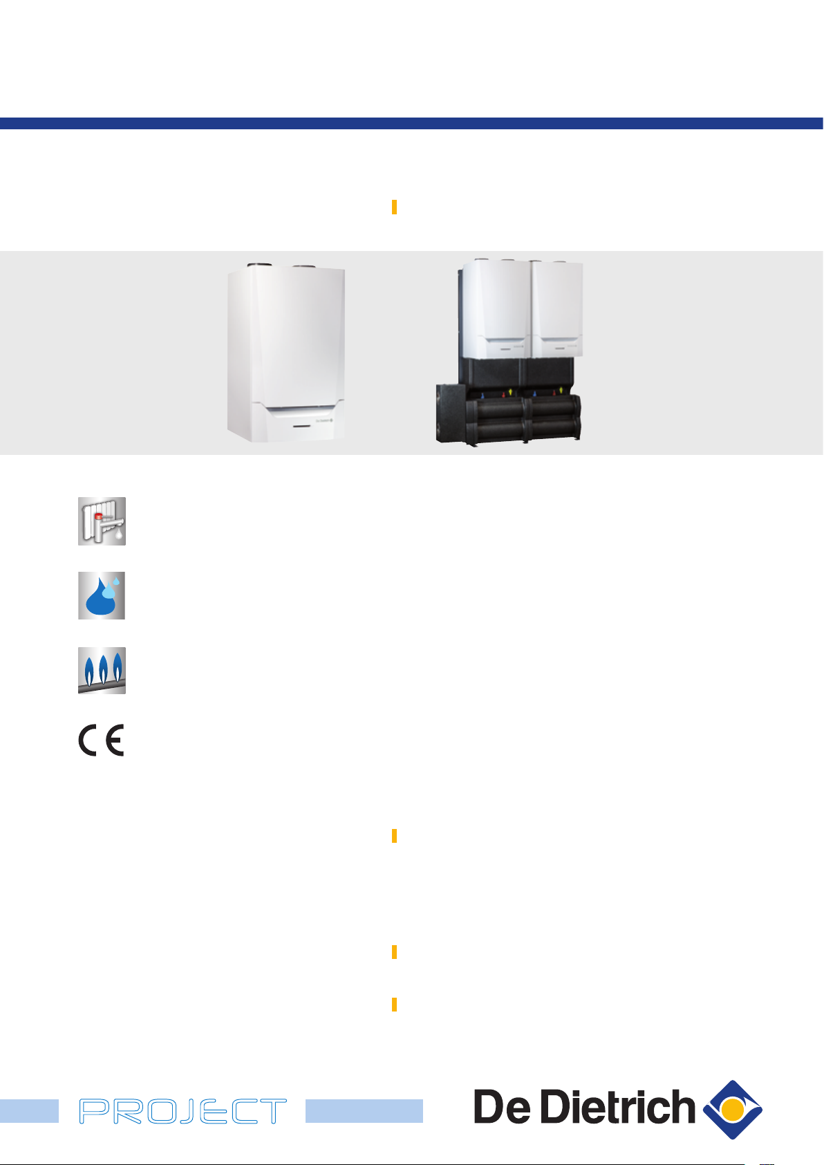
INNOVENS PRO MCA 160
SUSTAINABLE COMFORT
®
WALL-MOUNTED GAS CONDENSING BOILER
MCA 160: from 34.7 to 161.6 kW for heating only
MCA 160 MCA 160 installed in cascade
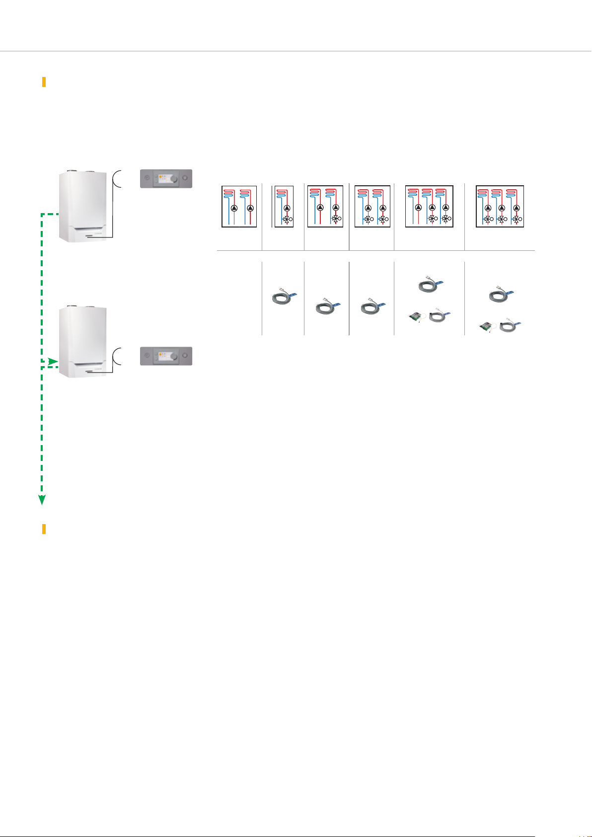
The INNOVENS PRO MCA 160 boiler can be supplied with a choice of either
Heating and domestic hot
water using an independent
tank
Condensation
All natural gases
Propane
of the following two control panels:
- DIEMATIC EVOLUTION: according to the options connected, this enables
command and control of up to 3 heating circuits according to the outside
temperature + 1 DHW circuit. It also allows optimised management of
combined systems and the control of 2 to 8 boilers in cascade configuration
(see page 5) when combined with boilers with the IniControl 2 panel (or
DIEMATIC EVOLUTION).
- IniControl 2: for operation via a 0-10V input, supplied with this panel
as standard. It is used as a secondary boiler as part of an installation in
cascade configuration, actuated by a boiler equipped with the DIEMATIC
EVOLUTION panel or in a cascade system where each boiler is controlled
via a 0-10V input.
CE identification no.:
0063CQ3781
PROJECT
Different air-flue gas connection configurations are possible; we offer
connection solutions using a horizontal or vertical forced flue, on a chimney
or bi-flow. MCA 160 units can be fitted in cascade only, or in combination
with MCA 45-115 boilers.
Complete hydraulic systems for connection of a cascade of 2 to 8 boilers
are available.
Operating cOnditiOns
Maximum operating pressure: 4 bar
Maximum operating temperature: 90°C
Safety thermostat; 110°C
Power supply: 230 V/50 Hz
International Protection marking: IP X1B
apprOval
B
23
- B
23P/B33
- C
13x
- C
33x
- C
93x
- C
- C63 - C
53
83
gas categOry
Equipped and preconfigured to operate using natural gas and propane
(with conversion kit)
NOx class: 6 (EN 15502-1)

PRESENTATION OF THE RANGE
The INNOVENS PRO MCA 160 gas condensing boiler is a new
high-power wall-mounted boiler. It boasts an innovative design and
a new aesthetic, with a sleek finish. Exceptionally compact (602 x
enhanced perfOrmance
- Efficiency up to 108.5%
- NOx class 6, in line with EN 15502-1
advantages
- Compact packaged heating body made from
aluminium/silicium alloy with a large heat exchange surface
area and moderate pressure losses, providing high resistance
to corrosion and only requiring a very low irrigation flow rate
(except for a flow temperature > 75°C) thanks to the burner
regulator device which manages the transition phases within
the installation which are the source of the very low flow rates
in the boiler. The front access facilitates maintenance,
- Stainless premix burner with braided metal fibre surface,
modulating the output from 18 to 100% to ensure the comfort
level meets requirements, equipped with an air intake silencer.
Low CO and NOx emissions, enabling optimum protection of
the environment,
- Gas line with non-return valve,
Operates using natural gas and propane with conversion
kit
- The INNOVENS PRO MCA 160 boiler can be supplied with
either of the following two control panels:
• DIEMATIC EVOLUTION: suitable for all installation situations,
even the most complex; in its original configuration, it can
be used to control and regulate 2 direct circuits and up to 2
circuits with mixing valve (by adding 2 optional flow sensors).
Add a PCB + sensor to enable a third circuit with mixing
valve to be actuated. A DHW sensor can be fitted to enable
regulation with the DHW circuit prioritised. It is specially
designed to allow optimisation of combined systems.
This control panel can also be used to control an installation
in cascade configuration, where just the first boiler will be
600 x 1 112 mm for 160 kW), is its very easy to install and maintain.
It is supplied assembled and factory-tested.
- Low pollutant emissions: NOx < 39 mg/kWh.
equipped with this panel, and "slave" boilers will be equipped
with an IniControl 2 control panel. To connect more than
the 3 circuits available on the master boiler, it is possible to
insert 1 (or several) additional boiler(s) with the DIEMATIC
EVOLUTION panel into the cascade
• IniControl 2: this is mainly used in installations (cascade or
non-cascade) with an external control cabinet to control all
of the secondary circuits via a 0-10V input, which this panel is
fitted with as part of its original equipment,
- A range of equipment such as an automatic air vent, PPS
flue gas pipes, air-flue gas connection parts with measuring
ports, mains connection cable, internal lighting, heating pump
connector and signalling connector, wall mounting bracket, and
a siphon for draining the condensates,
- Complete cascade hydraulic systems for 2 and up to
8 boilers for installations between 300 and 1216 kW; see
page 12,
- Complete cascade hydraulic systems combining MCA
45/115 and MCA 160 units are also available; see page 17.
- Multiple options to ensure these boilers are as easy to
operate as possible:
• hydraulic connection kit comprising the flow/return valves, the
gas valve, the safety valve, and the filling valve
• primary pump, low-loss header, condensate neutralisation
tray, etc.
- Air-flue gas connection possible via horizontal or vertical
forced flue, on a chimney or bi-flow (see page 22).
MODELS AVAILABLE
Boiler
For heating only
(option to connect a
domestic hot water
tank*)
MCA_Q0200
*Only in combination with the DIEMATIC EVOLUTION control panel
2
Control
DIEMATIC EVOLUTION
IniControl 2
panel
INNOVENS PRO
model
MCA 160 DIEMATIC EVOLUTION
MCA_Q0211MCA_Q0212
MCA 160 IniControl 2
Power range (kW)
at 50/30°C at 80/60°C
34.7 to 161.6 31.5 to 152.1
TECHNICAL SPECIFICATIONS
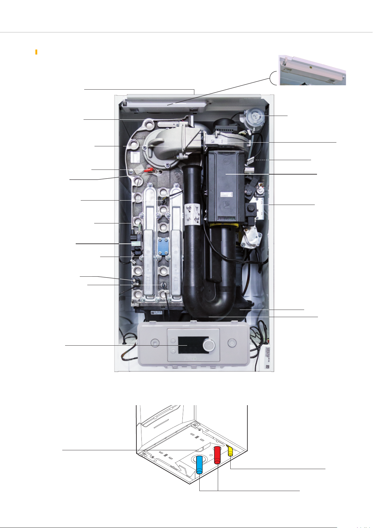
descriptiOn
Air-flue gas connection
with measuring port
(not visible)
Flow temperature sensor
Gas line with non-return valve
Ionisation/ignition electrode
Flame inspection
window
Exchanger temperature
sensor
Packaged heating body made
from aluminium/silicium alloy
Ignition transformer
Heat exchanger inspection hatch
Detail of the boiler internal
Differential pressure switch (air)
Automatic air vent
lighting
Fan
(not visible)
Operating unit
Gas valve block
MCA_Q0011
Water pressure sensor
Return temperature sensor
Control panel
- DIEMATIC EVOLUTION: see p. 7
- IniControl 2: see p. 9
View of the boiler from underneath
Location for
siphon connection
Condensate manifold
Intake silencer
MCA_Q0210
MCA_F0088
Gas inlet
Heating flow and return
3
TECHNICAL SPECIFICATIONS
5050
1045
200
5050
5050
100 100
229
46
80
1045
175 110185
300
600
130
1112
214
4
1
243
the technical specificatiOns
Boiler
Generator type: heating only
Boiler type: condensing
NOx class: 6
Burner: premix burner
Boiler type MCA 160
Useful output
Nominal output Pn at 50/30°C kW 161 . 6
Efficiency in % LHV, load...%
and water temp.... °C
Useful efficiency at …%
of the rated heat output (2)
Nominal water flow rate at Pn and ∆t = 20 K m
Stand-by losses at ∆t = 30 K W 191
Electrical output of auxiliaries at Pn_gen W 275
Electrical output of auxiliaries in standby W 5
Useful output at 50/30°C min./max. kW 34.7-161.6
Useful output at 80/60°C min./max. kW 31 .5-152.1
Flue gas mass flow rate min./max. kg/h 57/277
Flue gas temperature min./max. °C 32/66
Pressure available at boiler outlet Pa 200
Water content l 17
Minimum required water flow rate * m
Water side pressure drop at ∆t = 20 K mbar 17 0
Max. gas flow rate
(15°C-1013 mbar)
Weight (empty) kg 147
* for operation at > 75°C, the minimum flow rate must be calculated at ∆t = 45 K
(1) Q
nom = nominal heat output
- nominal determined at Q
- intermediate at 30% Q
- 100% Pn at av. temp. 70°C % 9 7. 5
- 30% Pn at return temp. 30°C % 108.5
- at 30 Eta 1 % 9 7. 8
- at 100% Eta 4 % 8 7. 8
- natural gas H/L m
- propane m
Energy used:
natural gas or propane
Combustion evacuation:
chimney or sealed
nom (1) kW 15 2 .1
nom (1) kW 50.8
Average operating temperature:
- O
- O
pT_max
pT_min
: 85°C
: 25°C
“CE certificate” ref.: CE 0063CQ3781
3
/h 6.5
3
/h 0.4
3
/h 16.5/19.6
3
/h 6.3
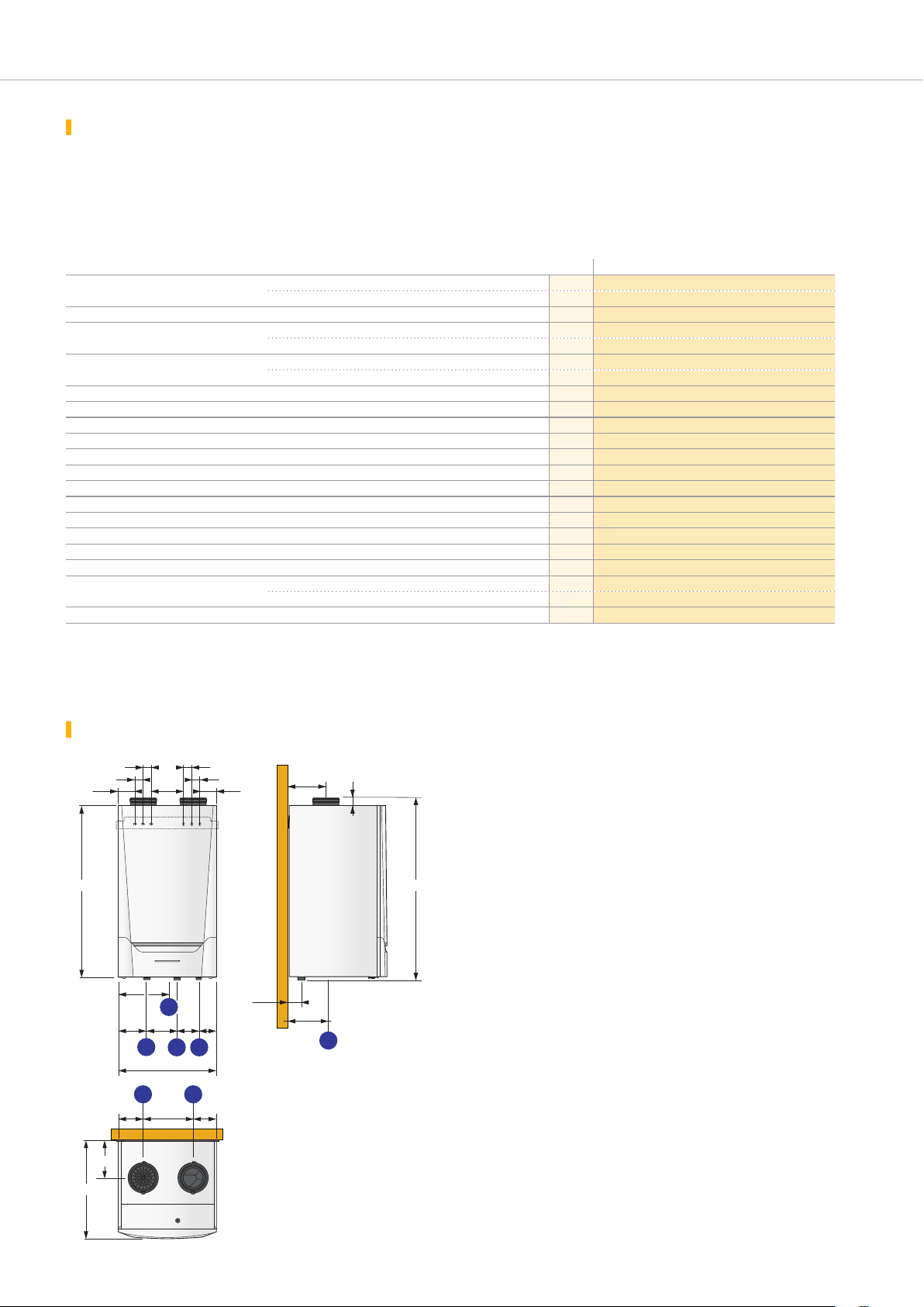
main dimensiOns (in mm and inches)
100 100
226
200
300
175 110185
1
600
5 6
130
243
305152 143
5050
80
229
214
46
1112
Heating return R 1" 1/4
Heating flow R 1" 1/4
Gas inlet R 1"
Condensate discharge (siphon
supplied)
4
MCA_F0225
Air supply pipe Ø 150 mm
Combustion product discharge
Ø 150 mm
602
4
SELECTING THE CONTROL PANEL
M
M
M M M
M M M M M MM M
M
M
M M M
M M M M M MM M
M
M M M
M M M M M MM M
M M
M M M
M M MM M
M M M
M
M
M M M
M M M M M MM M
M
M
M M M
M M M M M MM M
M
M M M
M M M M M MM M
M M
M M M
M M MM M
M M M
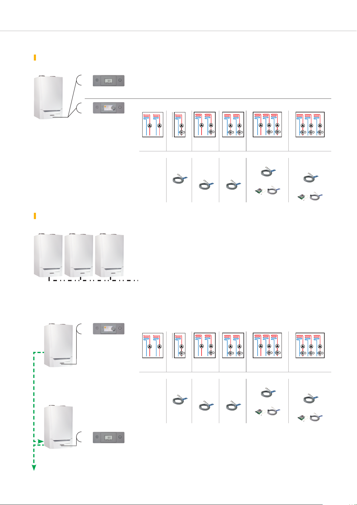
The control panel is selected based on the installation to be created:
installatiOn with 1 single bOiler
Two types of panel are possible
- For installations with 0-10 V control cabinet in a boiler room.
IniControl 2
or
- For control of one circuit:
DIEMATIC Evolution
MCA 160…
M
M
M M
M M
MM M
2 x direct
Options:
standard 1 flow sen-
installatiOn Of 2 tO 8 bOilers in cascade
With IniControl 2 control panels
All the boilers will be connected via a 0-10 V input to a control cabinet in the boiler room
which will manage all the secondary circuits (see p. 22).
0-10 V
MCA 160
IniControl 2
With DIEMATIC EVOLUTION control panel for the 1st
and 1 IniControl 2 panel for each of the secondary boilers
MCA 160
IniControl 2
MCA 160
IniControl 2
boiler in the cascade (master boiler)
- For control of one circuit:
valve
sor AD199
direct
+ 1 valve
1 flow
sensor
AD199
2 x valve
2 flow
sensors
AD199
direct
+ 2 x with valve
1 flow sensor AD199
+ 1 PCB AD249
3 x with valve
2 flow sensors
AD199
+ 1 PCB AD249
Boiler 1
MCA 160 DIEMATIC EVOLUTION
(master)
BUS
Boilers 2 to 8
MCA 160 IniControl 2
(secondary)
DIEMATIC Evolution
IniControl 2
2 x direct
valve
M
direct
+ 1 valve
M
M M
2 x valve
+ 2 x with valve
direct
M M
3 x with valve
Options:
standard 1 flow sen-
sor AD199
1 flow
sensor
AD199
2 flow
sensors
AD199
1 flow sensor AD199
+ 1 PCB AD249
2 flow sensors
+ 1 PCB AD249
- No additional secondary circuit may be connected to the IniControl 2 panel.
MM M
AD199
5
SELECTING THE CONTROL PANEL
M
M
M M M
M M M M M MM M
M
M
M M M
M M M M M MM M
M
M M M
M M M M M MM M
M M
M M M
M M MM M
M M M
installatiOn Of 2 tO 8 bOilers in cascade (cOntinued)
To connect more than 3 heating circuits to a cascade installation,
one of the MCA 160 IniControl 2 boilers in the cascade must
be replaced with one (or several, depending on the number
With a DIEMATIC EVOLUTION control panel for the first boiler in the cascade (master boiler)
and 1 or several DIEMATIC EVOLUTION panels for each of the secondary boilers
- For control of one circuit:
DIEMATIC Evolution
of additional circuits to be managed) MCA 160 DIEMATIC
EVOLUTION boiler(s) (see example in the hydraulic diagram on
page 36).
Boiler 1
MCA 160 DIEMATIC EVOLUTION
(master)
BUS
DIEMATIC Evolution
Boiler 2
MCA 160 DIEMATIC EVOLUTION
(secondary)
Boilers 3 to 8
MCA 160 IniControl 2 or
MCA 160 DIEMATIC EVOLUTION
if necessary (secondary)
2 x direct
valve
M
direct
+ 1 valve
M
M M
2 x valve
+ 2 x with valve
direct
M M
3 x with valve
Options:
standard 1 flow sen-
sor AD199
1 flow
sensor
AD199
2 flow
sensors
AD199
1 flow sensor AD199
+ 1 PCB AD249
2 flow sensors
AD199
+ 1 PCB AD249
- Management of circuits 4, 5 and 6, if applicable (see above).
- 1 or several DIEMATIC EVOLUTION panels according to the number of circuits to be
managed.
MM M
dhw prOductiOn
The DIEMATIC EVOLUTION control panel includes the “priority
DHW” function, and can therefore be completed with 1 or
6
2 DHW sensors - package AD212 for the control of one or
2 independent tanks.
THE DIEMATIC EVOLUTION CONTROL PANEL
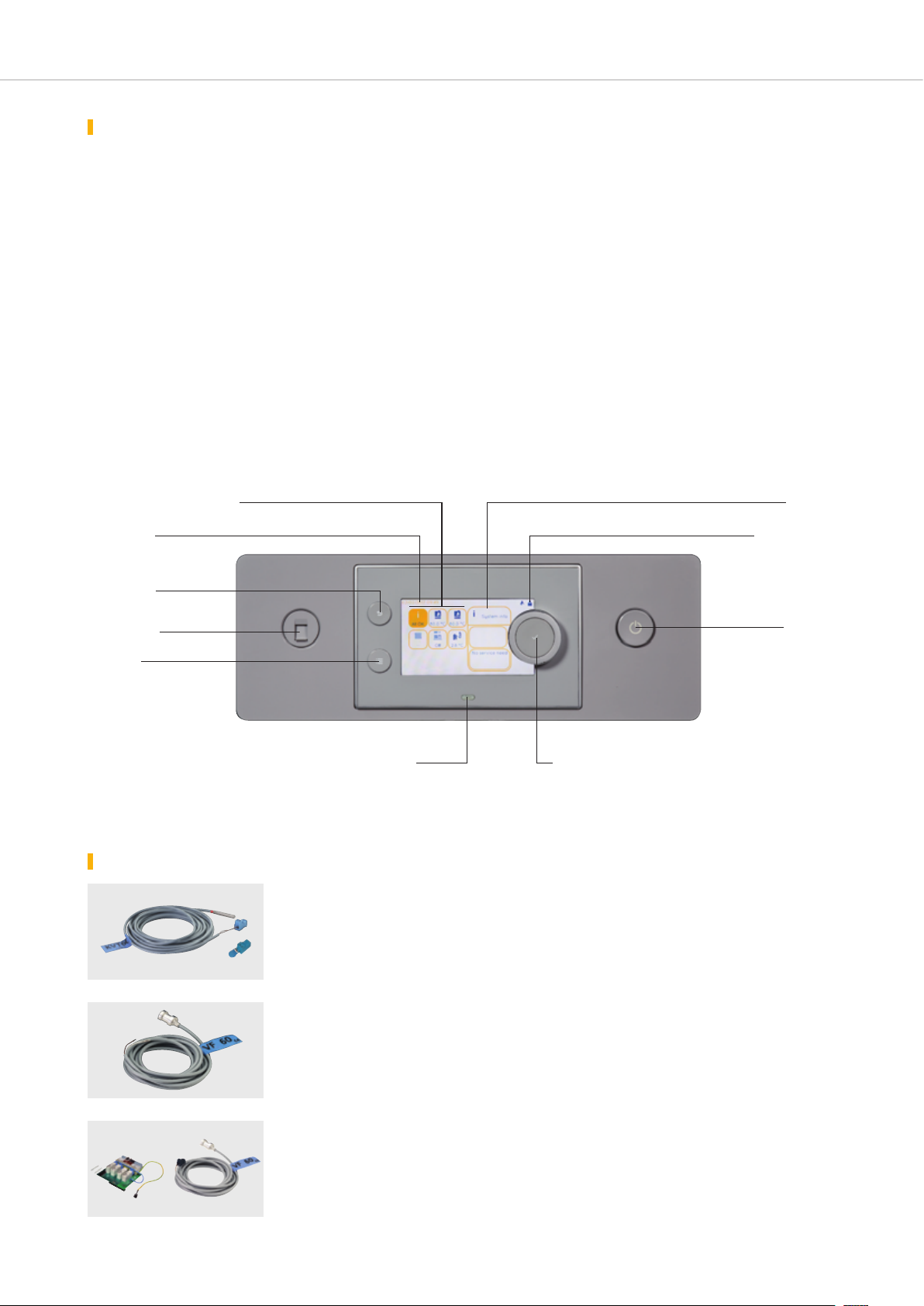
presentatiOn Of the DIEMATIC EVOLUTION control panel
The DIEMATIC EVOLUTION control panel is a highly
advanced panel with new ergonomic controls, integrating a
programmable electronic control system which modulates the
boiler temperature by acting on the modulating burner, based
on the outside temperature (outside sensor delivered) and the
room temperature, where required, if an interactive remote
control (supplied as an option) is connected.
As standard, the DIEMATIC EVOLUTION is able to automatically
run a central heating system with a direct circuit without mixing
valve and 1 circuit with mixing valve (please note: the flow
sensor - package AD199 - must be ordered separately).
By simply adding 1 “PCB + sensor for 1 valve circuit” option
(package AD249), it will be possible to control up to 3 circuits
in total, with the option to equip each of these circuits with a
remote control (option).
Pictograms with info on the installation
(circuit temperature, outside air
temperature, circuits, etc.)
Date and time
Button to return to
the previous
level or menu
Socket for the
PC connection
Button for
the main display
The connection of a domestic hot water sensor enables the
programming and control of a DHW circuit (package AD212 option).
This control system has been specifically developed to enable
optimal management of systems combining different
heating generators (boiler + heat pump or + solar system…).
It allows the installer to configure the entire heating system, no
matter how complex.
For larger installations, it is also possible to connect 2 to
7 boilers in cascade configuration.
The DIEMATIC EVOLUTION panel will then be used as the
master for the installation, with the secondary boilers equipped
with the IniControl 2 control panel. To connect more than the
3 circuits available on the master boiler, a second boiler (or
several boilers) with DIEMATIC EVOLUTION can be included in
the cascade.
Dialogue and
information fields
Current menu display
On/Off button
Status indicator LED:
- fixed green = normal operation
- flashing green = warning
- red = blockage
- continuous red = locked
the DIEMATIC EVOLUTION control panel options
Sensor for domestic hot water (length 5 m) - Package AD212
It allows regulation with temperature prioritised and
programming of domestic hot water production via
an independent tank.
8518Q022GT220_Q0002
Flow sensor downstream of valve (length 2.5 m) - Package AD199
This sensor is necessary for connecting the first
circuit with mixing valve on a boiler equipped with
the DIEMATIC EVOLUTION control panel.
PCB + sensor for 1 mixing valve - Package AD249
It allows a mixing valve with an electromechanical
or electrothermal motor to be controlled. The PCB
is inserted in the DIEMATIC EVOLUTION panel and
MCA_Q0013
MCA_Q0211
Rotary/push button:
- turn to select a menu or parameter
- press to confirm the selection
Can be used as a cascade flow sensor.
is connected using plug-in connectors. DIEMATIC
EVOLUTION can house 1 “PCB + sensor” option,
enabling it to control 1 additional mixing valve.
7
THE DIEMATIC EVOLUTION CONTROL PANEL
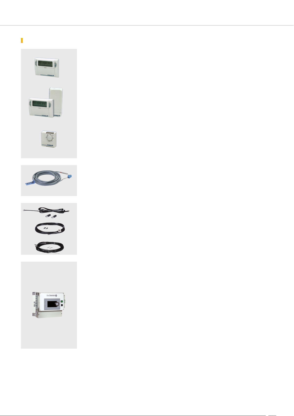
the DIEMATIC EVOLUTION control panel options
AD137
AD200
AD140
Wired programmable room thermostat - Package AD137
Wireless programmable room thermostat - Package AD200
Non-programmable room thermostat - Package AD140
Programmable thermostats provide weekly
programming and regulation of the heating by
8801Q0028666Q120A
activating the burner according to the various
operating modes: “Automatic” depending on the
programming, “Permanent” at a set temperature or
a receiver box to be mounted on the wall close to
the boiler.
The non-programmable thermostat is used to
regulate the room temperature based on the set
point, by activating the burner.
“Holiday”. The "wireless" version is delivered with
8801Q003
Sensor for buffer tank - Package AD250
Comprises 1 sensor for managing a buffer
Can be used as a cascade flow sensor.
tank with a boiler equipped with a DIEMATIC
EVOLUTION control panel.
8518Q022
AD308
AD310
AD309
S-BUS cable with plugs, 1 .5 m - Package AD308
S-BUS cable with plugs, 12 m - Package AD309
S-BUS cable with plugs, 20 m - Package AD310
The BUS cable enables two boilers equipped with
the DIEMATIC EVOLUTION or IniControl 2 panel
to be connected as part of a cascade installation.
MCA_Q01149-MCA_Q01150-MCA_Q0151
DIEMATIC VM EVOLUTION control system (wall-mounted) - Package AD315
(Available first quarter 2018)
The DIEMATIC VM EVOLUTION electronic control
system, integrated into a wall unit, allows 3 heating
circuits and 2 DHW circuits to be controlled and
regulated; each of the heating circuits can be a
direct circuit or a circuit with a 3-way motorised
mixing valve.
- DIEMATIC VM EVOLUTION can be integrated
into a DIEMATIC iSystem via the Modbus as
supplementary only.
- DIEMATIC VM EVOLUTION can control a
cascade of boilers equipped with an IniControl 2
control panel.
It is possible to link together up to 8* DIEMATIC
VM EVOLUTION control systems and to thereby
create numerous combinations, regardless of the
* 1 “master” control system + 7 “slave” control
systems.
type of installation:
- DIEMATIC VM EVOLUTION can be used in
relation with one or several generators equipped
VM_Q0009
with DIEMATIC EVOLUTION or IniControl 2.
8
The IniControl 2 CONTROL PANEL
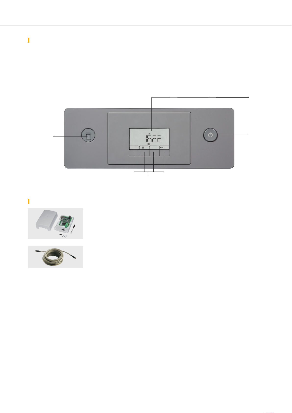
presentatiOn Of the IniControl 2 control panel
The IniControl 2 control panel is used to manage the boiler
(without programming) via a configurable 0 - 10 V signal. For a
cascade installation, the IniControl 2 panel will be fitted to the
secondary boilers linked in series to the master boiler equipped
with the DIEMATIC EVOLUTION panel via the BUS cable
(option).
Socket for the
PC connection
The boiler temperature, heating network pressure, and generator
operating status are displayed using alphanumeric codes and
symbols on a large screen integrating a flashing alarm function.
For monitoring the installation, there is an option to read the
fault log and the operating timer counters.
Digital display
(large format)
On/Off switch
MCA_Q0212
Keys:
- access to the various menus or parameters,
- setting, manual reset variant according to the selections
inicOntrOl 2 cOntrOl panel options
ModBUS - OpenTherm interface - Package AD286
As part of a “mixed” cascade, this interface must
be affixed to the wall close to the MCA 160 boiler,
VM_Q00038227_Q020
BUS connection cable (12 m) - Package AD314
Enables a link to be created between 2 boilers
equipped with DIEMATIC iSystem and IniControl/
IniControl 2 panels.
enabling the MCA 45/115 boiler to be connected
to the MCA 160.
9
THE BOILER OPTIONS
Pump output in W
3
Flow rate m3/h
Flow rate m
3
/h
: Proportional pressure
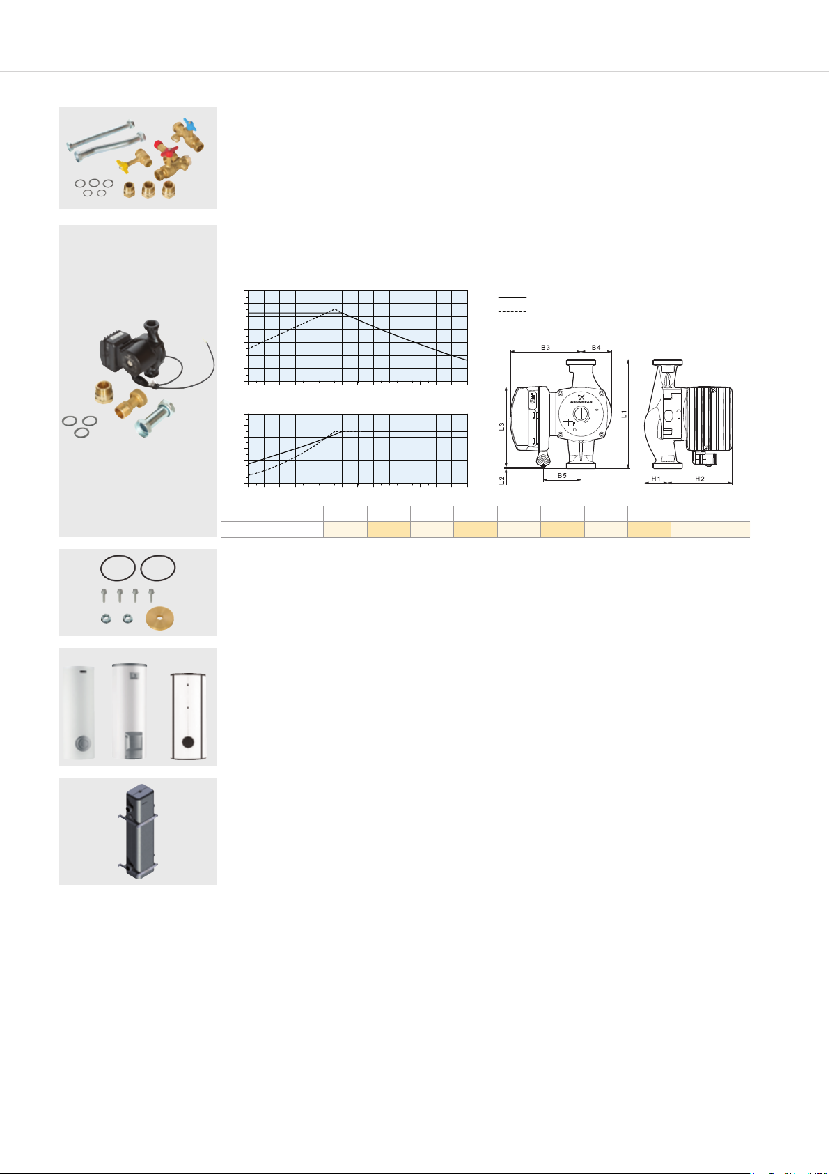
Hydraulic connection kit + gas valve - Package EH680
These kits comprise:
- 1 gas valve Rp 3/4,
- 1 heating return valve integrating the filling and
MCA_Q0206
drain valve Rp 1 1/4,
Modulating primary heating pump (EEI < 0.23) - Package EH651
Specifications for the GRUNDFOS UPMXL 25-105 130 AUTO pump
14
12
10
8
6
4
2
Manometric height in mWG
0
0.0 0.5 1.0 1.5 2.0 2.5 3.0 3.5 4.0 4.5 5.0 5.5 6.0 6.5 7.0
240
200
160
120
80
40
0
0.0 0.5 1.0 1.5 2.0 2.5 3.0 3.5 4.0 4.5 5.0 5.5 6.0 6.5 7.0
Dimensions (mm)
MCA_Q0205
UPMXL 25-105 13 0 22 131 117 50 64 27 112 G 1 1/2
- 1 heating flow valve with 3-bar safety valve and
port for connecting the expansion vessel Rp 1 1/4.
: Constant pressure
Flow rate m3/h
3
MCA_F0501
3
/h
Flow rate m
L1 L2 L3 B3 B4 B5 H1 H2 Connection
Type XXXX XX-XX XXX
XXXV ~
XX/XXHz
GFXXX
EEI<0.23
EuP Ready
1/1(A)
I
P
(W)
1
XX
X.XX
XX
X.XX
Max.
Min.
A
High Efficiency
P/N:XXXXXXX
PC:XXXXXX
XX
IP XX
TF XX
Max.X.XMPa
MCA_F0502
BLC
BPB B…
BLC_Q0001A
BPB_Q0001A
Propane conversion kit - EH693
This kit comprises a diaphragm which must be
installed on the gas valve unit to enable operation
with propane.
Domestic hot water preparation
The De Dietrich independent tanks in the B…
series, with a capacity of 150 to 3000 litres,
enable the production of domestic hot water for
individual and collective housing and industrial
RSB_Q0004A
Low-loss header, 120/80 - 2” - Package GV47
For any installations with several circuits or for
cascade installations, the use of a low-loss header
is strongly recommended.
MCA_Q0138 MCA_Q0204
and commercial premises. The specifications and
performance of these tanks is given in the price
catalogue and respective technical brochures.
The header is supplied with insulation and fitted
with a wall-mounting bracket and an accessories kit
comprising a plug, an air vent and a 1/2" drain valve.
10
THE BOILER OPTIONS
SA3
DU15
SA4
Gravity flow condensate neutralisation station (up to 450 kW) - Package SA3
Condensate neutralisation station with lift pump:
- Package SA4 for boilers or cascades of boilers up to 300 kW
- Package DU15 for boilers or cascades of boilers up to 1300 kW
C330_Q0005
The materials used for the condensate drain pipes
must be appropriate. Otherwise, the condensate
must be neutralised.
C330_Q0008
C330_Q0006
3
2
Mini
150 mm
1
Principle: Acid condensates are conveyed via a
reservoir filled with granulates before being sent to
the wastewater network.
Condensate draining
Condensate neutralisation station
Siphon
MCA_F0086
Granulate recharge for neutralisation station - Ref. 9422-5601 (10 kg)
Granulate recharge for neutralisation station - Package SA7 (25 kg)
An annual inspection of the system is required,
including a check of the effectiveness of the
C330_Q0009
granulates via a pH measurement. If necessary,
the granulates must be replaced.
300 mbar gas pressure regulator: - GDJ 20 - Package SA12
- GDJ 25 - Package AD245
- GDJ 50 - Package AD246
It is fitted on the gas inlet circuit. It is needed if the
gas is supplied at a pressure of 300 mbar.
Regulator
GDJ 20 24 240 Rp 3/4”
GDJ 25 70 700 Rp 1”
C230_Q0002
GDJ 50 14 0 1400 Rp 2”
Max. natural gas flow rate
in m
3
/h
Max power consumed
in kW
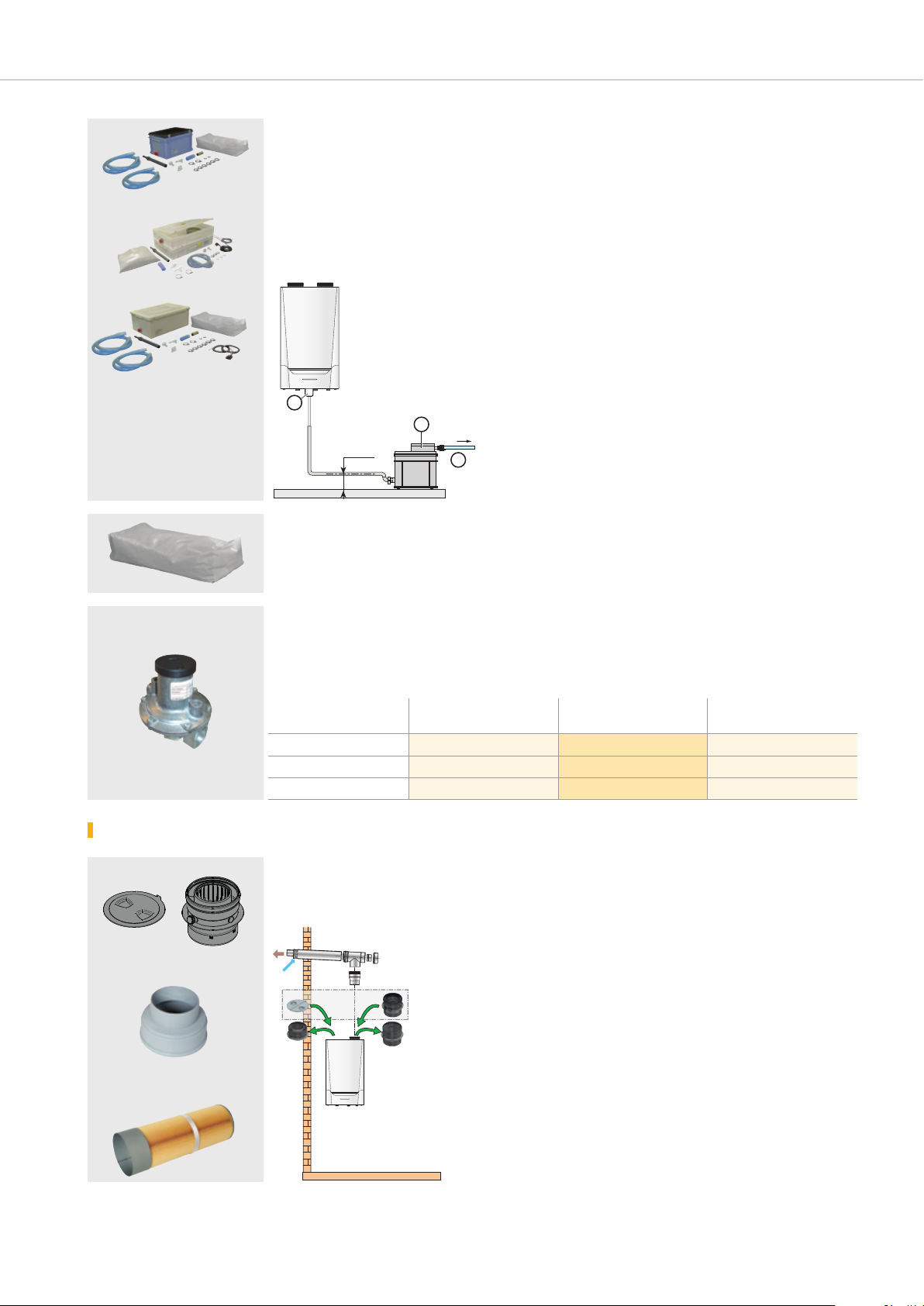
flue system accessOries specific tO the innOvens prO mca 160 bOiler
EH692
EH645
Concentric air-flue gas connection conversion kit - Package EH692
Ø 150 mm to Ø 200 mm adapter - Package EH645
Air filter - Package EH646
FUMI_F0216
EH692
MCA_Q0209
Connection
Ø
EH646
MCA_Q0203
MCA_F0090
11
 Loading...