

DeDietrich MCA 45 - 65 - 90 - 115, Innovens Pro MCA 45, Innovens Pro MCA 65, Innovens Pro MCA 90, Innovens Pro MCA 115 Installation And Service Manual

Ireland
Innovens Pro
EN
Wall-hung gas condensing boilers
MCA 45 - 65 - 90 - 115
Installation and
Service Manual
300024755-001-A
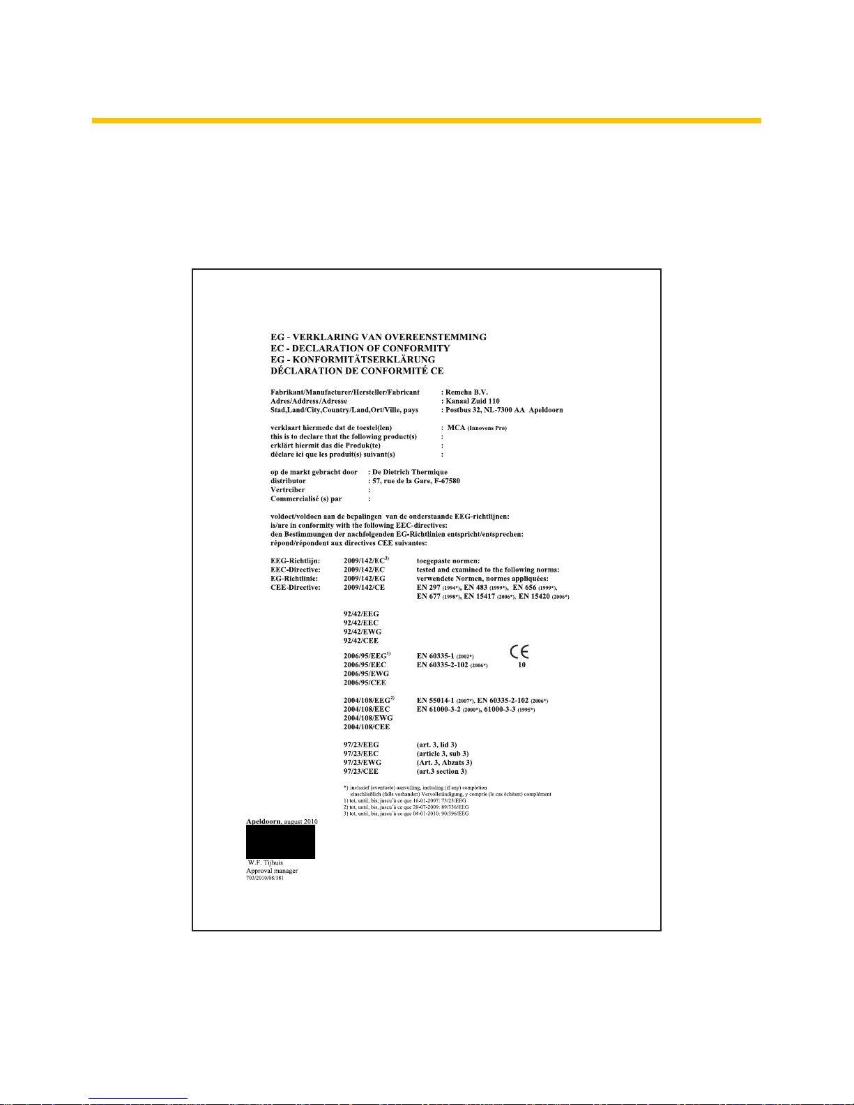
EG declaration of conformity
The device complies with the standard type described in the EG
declaration
of conformity. It was manufactured and commissioned in
accordance with European directives.
The original of the declaration of compliance is available from the
manufacturer.
R000040-A

Contents
1 Introduction ................................................................................................6
1.1 Used symbols .......................................................6
1.2 Abbreviations ........................................................6
1.3 General ..................................................................7
1.3.1
Manufacturer's liability .............................................7
1.3.2 Installer's liability .....................................................7
1.3.3 User's liability ..........................................................7
1.4 Homologations ......................................................8
1.4.1 Certifications ...........................................................8
1.4.2 Equipment categories .............................................8
1.4.3 Additional Directives ................................................8
1.4.4 Factory test .............................................................9
2 Safety instructions and recommendations ............................................10
2.1 Safety instructions .............................................10
2.2 Recommendations ..............................................10
3 Technical description ..............................................................................12
3.1 General description ............................................12
3.2 Main parts ............................................................12
3.3 Operating principle .............................................12
3.3.1 Shunt pump ...........................................................12
3.3.2 System in cascade ................................................13
3.3.3 Calorifier connection .............................................13
3.3.4 Water flow rate ......................................................13
3.4 Technical characteristics ...................................13
3.4.1 Sensor characteristics ...........................................15
4 Installation ................................................................................................16
4.1 Regulations governing installation ...................16
4.2 Package list .........................................................16
4.2.1 Standard delivery ..................................................16
4.2.2 Accessories ...........................................................16
4.3 Choice of the location ........................................18
4.3.1 Data plate ..............................................................18
4.3.2 Location of the appliance ......................................18
4.3.3 Ventilation .............................................................19
06/09/2010 - 300024755-001-A
1

4.3.4 Main dimensions ...................................................20
4.4 Positioning the boiler .........................................21
4.5 Hydraulic connections .......................................21
4.5.1
Flushing the system ..............................................21
4.5.2 Connection of the heating circuit ...........................22
4.5.3 Connecting the expansion vessel .........................23
4.5.4 Connecting the condensate discharge pipe ..........24
4.6 Gas connection ...................................................24
4.7 Flue gas system connections ............................25
4.7.1 Classification .........................................................25
4.7.2 Lengths of the air/flue gas pipes ...........................26
4.8 Installing the outside sensor .............................27
4.8.1 Choice of the location ............................................27
4.8.2 Installing the outside sensor ..................................28
4.9 Electrical connections ........................................28
4.9.1 Control unit ............................................................28
4.9.2 Recommendations ................................................29
4.9.3 Fitting and connecting the control panel ...............30
4.9.4 Position of the PCBs .............................................30
4.9.5 Accessing the connection terminal blocks ............31
4.9.6 Connecting the pump ............................................32
4.9.7 Connecting a direct heating circuit ........................34
4.9.8 Connecting a direct heating circuit and a domestic hot
water tank ..............................................................35
4.9.9 Connecting two circuits and a domestic hot water tank
after the mixing tank ..............................................36
4.9.10 Hot water storage tank connection ........................38
4.9.11 Pool connection .....................................................44
4.9.12 Connecting a mixed tank .......................................46
4.9.13 Connecting the options .........................................47
4.9.14 Connection in cascade ..........................................49
4.10 Electrical diagram ...............................................51
4.11 Filling the system ...............................................52
4.11.1 Water treatment ....................................................52
4.11.2 Filling the siphon ...................................................53
4.11.3 Filling the system ..................................................53
5 Start-up - DIEMATIC iSystem ..................................................................54
5.1 Control panel .......................................................54
5.1.1 Description of the keys ..........................................54
5.1.2 Description of the display ......................................55
5.1.3 Access to the various browsing levels ..................57
5.1.4 Browsing in the menus ..........................................58
5.2 Check points before commissioning ................59
5.2.1 Preparing the boiler for commissioning .................59
5.2.2 Gas circuit .............................................................60
5.2.3 Hydraulic circuit .....................................................60
Contents
06/09/2010 - 300024755-001-A
2

5.2.4 Electrical connections ...........................................60
5.3 Putting the appliance into operation ................60
5.4 Gas settings ........................................................62
5.4.1
Adapting to another gas type ................................62
5.4.2 Setting the air/gas ratio (Full load) ........................62
5.4.3 Setting the air/gas ratio (Part load) ......................64
5.5 Checks and adjustments after
commissioning ...................................................65
5.5.1 Displaying the parameters in extended
mode .....................................................................65
5.5.2 Setting the parameters specific to the
installation .............................................................66
5.5.3 Naming the circuits and generators ......................68
5.5.4 Setting the heating curve ......................................69
5.5.5 Finalizing work ......................................................71
5.6 Reading out measured values ...........................72
5.7 Changing the settings ........................................73
5.7.1 Language selection ...............................................73
5.7.2 Calibrating the sensors .........................................73
5.7.3 "Professional" settings ..........................................75
5.7.4 Configuring the network ........................................81
5.7.5 Return to the factory settings ................................87
6 Start-up - IniControl .................................................................................88
6.1 Control panel .......................................................88
6.1.1 Description of the keys ..........................................88
6.1.2 Description of the display ......................................89
6.2 Check points before commissioning ................90
6.2.1 Preparing the boiler for commissioning .................90
6.2.2 Gas circuit .............................................................91
6.2.3 Hydraulic circuit .....................................................91
6.2.4 Electrical connections ...........................................91
6.3 Putting the appliance into operation ................92
6.4 Gas settings ........................................................93
6.4.1 Adapting to another gas type ................................93
6.4.2 Setting the air/gas ratio (Full load) ........................93
6.4.3 Setting the air/gas ratio (Part load) ......................94
6.5 Checks and adjustments after
commissioning ...................................................95
6.5.1 Setting the heating curve ......................................95
6.5.2 Finalizing work ......................................................96
6.6 Reading out measured values ...........................97
6.6.1 Reading out measured values ..............................97
6.6.2 Readout from the hour counter and percentage of
successful starts ....................................................99
06/09/2010 - 300024755-001-A
3

6.6.3 Status and sub-status ...........................................99
6.7 Changing the settings ......................................100
6.7.1
Description of the parameters .............................100
6.7.2 Modification of the installer-level parameters ......103
6.7.3 Setting the maximum heat input for central heating
operation .............................................................104
6.7.4 Return to the factory settings "Reset Param" ......105
6.7.5 Carrying out an auto-detect .................................105
7 Switching off the appliance ...................................................................106
7.1 Installation shutdown .......................................106
7.2 Frost protection ................................................106
8 Checking and maintenance ...................................................................107
8.1 General instructions .........................................107
8.2 Chimney sweep instructions ...........................107
8.2.1 Control panel DIEMATIC iSystem .......................107
8.2.2 Control panel IniControl ......................................108
8.3 Customising maintenance ...............................108
8.3.1 Maintenance message ........................................109
8.3.2 Installer's contact details .....................................110
8.4 Standard inspection and maintenance
operations .........................................................110
8.4.1 Checking the hydraulic pressure .........................110
8.4.2 Checking the ionisation current ...........................111
8.4.3 Checking the tightness of the combusted gases
evacuation and air inlet connections ...................111
8.4.4 Checking combustion ..........................................111
8.4.5 Checking the automatic air vent ..........................112
8.4.6 Checking the siphon ............................................113
8.4.7 Checking the burner and cleaning the heat
exchanger ...........................................................114
8.5 Specific maintenance operations ....................115
8.5.1 Inspection of the ignition electrode ......................115
8.5.2 Replacing the non-return valve ...........................116
8.5.3 Assembling the boiler ..........................................117
9 Troubleshooting .....................................................................................118
9.1 Anti-hunting ......................................................118
9.2 Messages (Code type Bxx or Mxx) ..................118
9.3 Message history ................................................121
9.3.1 Control panel DIEMATIC iSystem .......................121
9.3.2 Control panel IniControl ......................................122
Contents
06/09/2010 - 300024755-001-A
4

9.4 Faults (Code type Lxx or Dxx) .........................123
9.4.1
Control panel DIEMATIC iSystem .......................124
9.4.2 Control panel IniControl ......................................124
9.4.3 List of errors ........................................................124
9.4.4 Deletion of sensors from the memory in the
PCB .....................................................................132
9.4.5 Deleting the IOBL 3WV modules from the memory in
the PCB ..............................................................133
9.5 Failure history ...................................................133
9.5.1 Control panel DIEMATIC iSystem .......................133
9.5.2 Control panel IniControl ......................................134
9.6 Parameter and input/output check (mode
tests) ..................................................................135
9.6.1 Control panel DIEMATIC iSystem .......................135
9.6.2 Control panel IniControl ......................................137
9.6.3 Control system sequence ....................................137
10 Spare parts ..............................................................................................139
10.1 General ..............................................................139
10.2 Spare parts ........................................................139
10.2.1 Casing .................................................................140
10.2.2 Heat exchanger and burner - MCA 45 ................141
10.2.3 Heat exchanger and burner - MCA 65 ................142
10.2.4 Heat exchanger and burner - MCA 90/115 .........143
10.2.5 Fan - MCA 45/65 .................................................144
10.2.6 Fan - MCA 90 ......................................................145
10.2.7 Fan - MCA 115 ....................................................146
10.2.8 Control panel .......................................................147
10.2.9 Spare parts list ....................................................148
06/09/2010 - 300024755-001-A
5
1 Introduction
1.1 Used symbols
In these instructions, various danger levels are employed to draw the
user's attention to particular information.
In so doing, we wish to
safeguard the user's safety, obviate hazards and guarantee correct
operation of the appliance.
DANGER
Risk of a dangerous situation causing serious physical
injury.
WARNING
Risk of a dangerous situation causing slight physical
injury.
CAUTION
Risk of material damage.
Signals important information.
¼ Signals a referral to other instructions or other pages in the
instructions.
1.2
Abbreviations
4 3CE: Collective conduit for sealed boiler
4 DHW: Domestic hot water
4 Interscenario switch: Home
automation switch that can be used
to centralise and control several scenarios
4 IOBL: In One By Legrand - Carrier current home automation bus
4 PPS: Polypropylene hardly inflammable
4 PCU: Primary Control Unit - PCB for managing burner operation
4 PSU: Parameter Storage Unit - Parameter storage for PCBs
PCU and SU
4 SCU: Secondary Control Unit - control panel PCB
4 SU: Safety Unit - Safety PCB
1. Introduction MCA 45 - 65 - 90 - 115
6
06/09/2010 - 300024755-001-A

1.3 General
1.3.1. Manufacturer's liability
Our products are manufactured in compliance with the requirements
of the various european applicable Directives. They are therefore
delivered with [ marking and all relevant documentation.
In the interest of customers, we are continuously endeavouring to
make
improvements in product quality. All the specifications stated in
this document are therefore subject to change without notice.
Our liability as the manufacturer may not be invoked in the following
cases:
4 Failure to abide by the instructions on using the appliance.
4 Faulty or insufficient maintenance of the appliance.
4 Failure to abide by the instructions on installing the appliance.
1.3.2. Installer's liability
The installer is responsible for the installation and inital start up of the
appliance.
The installer must respect the following instructions:
4 Read and follow the instructions given in the manuals provided
with the appliance.
4 Carry out installation in compliance with the prevailing legislation
and standards.
4 Perform the initial start up and carry out any checks necessary.
4 Explain the installation to the user.
4 If a maintenance is necessary, warn the user of the obligation to
check the appliance and maintain it in good working order.
4 Give all the instruction manuals to the user.
1.3.3. User's liability
To guarantee optimum operation of the appliance, the user must
respect the following instructions:
4 Read and abide by the instructions given in the user manual.
4 Call on qualified professionals to carry out installation and initial
start up.
4 Get your fitter to explain your installation to you.
4 Have the required checks and services done.
4 Keep the instruction manuals in good condition close to the
appliance.
MCA 45 - 65 - 90 - 115 1. Introduction
06/09/2010 - 300024755-001-A
7
This appliance is not intended to be used by persons (including
children) whose physcial, sensory or mental capacity is impaired or
persons with no experience or knowledge, unless they have the
benefit, through the intermediary of a person responsible for their
safety, of supervision or prior instructions regarding use of the
appliance. Care should be taken to ensure that children do not play
with the appliance.
1.4
Homologations
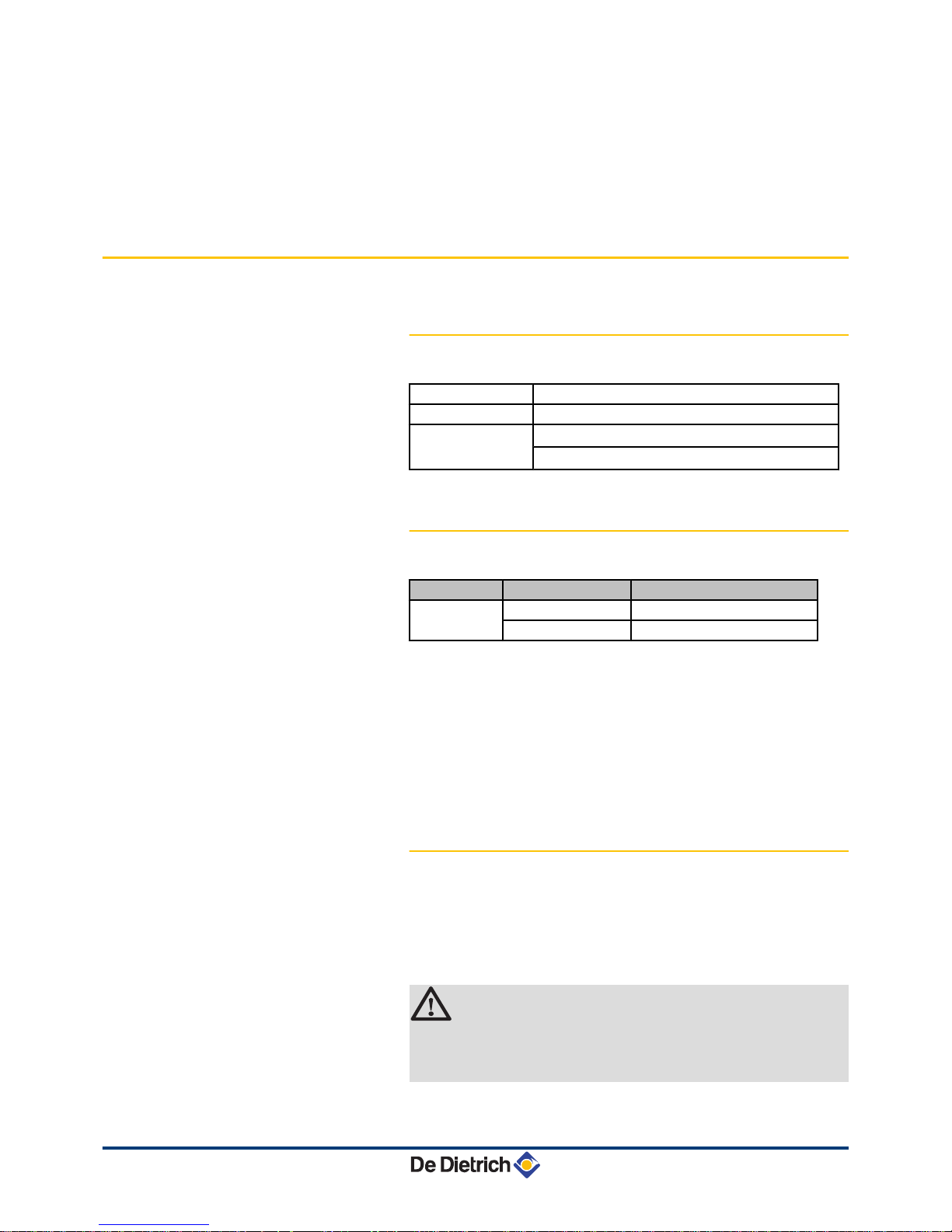
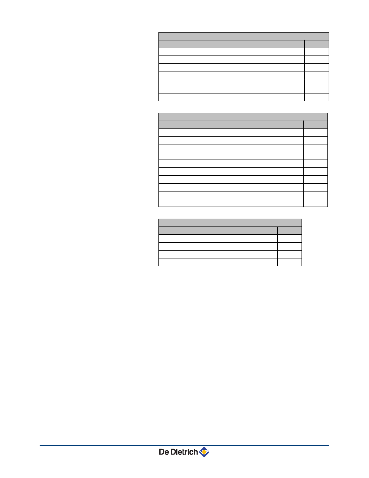
1.4.1. Certifications
CE identification no
PIN 0063CL3333
NOx classification
5 (EN 297 pr A3, EN 656)
Type of connection Chimney: B23, B
33
Flue gas outlet: C13, C33, C43, C53, C63, C83, C
93
1.4.2. Equipment categories
Gas category Gas type Connection pressure (mbar)
II
2H3P
Natural gas H (G20) 20
Propane (G31) 37
The boiler is preset in the factory to operate on natural gas H (G20).
For operation on another group of gases:
4 With DIEMATIC iSystem: ¼ "Adapting to another gas type",
page 62.
4 With IniControl: ¼ "Adapting to another gas type", page
93.
1.4.3.
Additional Directives
Apart from the legal provisions and Directives, the additional
Directives described in these instructions must also be observed
.
For all provisions and Directives referred to in these instructions, it is
agreed that all addenda or subsequent provisions will apply at the
time of installation.
WARNING
Installation of the appliance must be done by a qualified
engineer in accordance with prevailing local and national
regulations
.
1. Introduction MCA 45 - 65 - 90 - 115
8
06/09/2010 - 300024755-001-A

1.4.4. Factory test
Before leaving the factory, each boiler is set for optimum performance
and tested to check the following items:
4 Electrical safety
4 Adjustment (CO2)
4 Water tightness
4 Gas tightness
4 Parameter settings
MCA 45 - 65 - 90 - 115 1. Introduction
06/09/2010 - 300024755-001-A
9
2 Safety instructions and
recommendations
2.1 Safety instructions
DANGER
If you smell gas:
1.
Do not use a naked flame, do not smoke, do not
operate electrical contacts or switches ( doorbell,
light, motor, lift, etc..).
2. Isolate the gas supply.
3. Open the windows.
4. Trace possible leaks and seal them immediately.
5. If the gas leak is before the gas meter, contact the
gas supplier.
DANGER
If you smell flue gases:
1.
Switch the appliance off.
2. Open the windows.
3. Trace possible leaks and seal them immediately.
2.2 Recommendations
WARNING
4 Installation and maintenance of the boiler must be
carried out by a qualified professional in compliance
with prevailing local and national regulations.
4 When working on the boiler, always disconnect the
boiler from the mains and close the main gas inlet
valve.
4 After maintenance or repair work, check all
installations to ensure that there are no leaks.
CAUTION
The boiler must be installed in a frost-free environment.
Keep this document close to the place where the boiler is
installed.
Casing components
2. Safety instructions and recommendations MCA 45 - 65 - 90 - 115
10
06/09/2010 - 300024755-001-A

Only remove the casing for maintenance and repair operations. Put
the casing back in place after maintenance and repair operations.
Instructions stickers
The
instructions and warnings affixed to the appliance must never be
removed or covered and must remain legible during the entire lifespan
of the boiler. Immediately replace damaged or illegible instructions
and warning stickers.
Modifications
Modifications may only be made to the boiler after the written
permission of De Dietrich Thermique to do so.
MCA 45 - 65 - 90 - 115 2. Safety instructions and recommendations
06/09/2010 - 300024755-001-A
11
3 Technical description
3.1 General description
Wall-hung gas condensing boilers
4 High efficiency heating (Production of domestic hot water can be
ensured by a separate hot water calorifier).
4 Low pollutant emissions.
4 DIEMATIC iSystem or IniControl electronic control panel.
4 Flue gas evacuation by a forced flue, chimney or bi-flow type
connection.
4 Very suitable for cascade systems with several boilers.
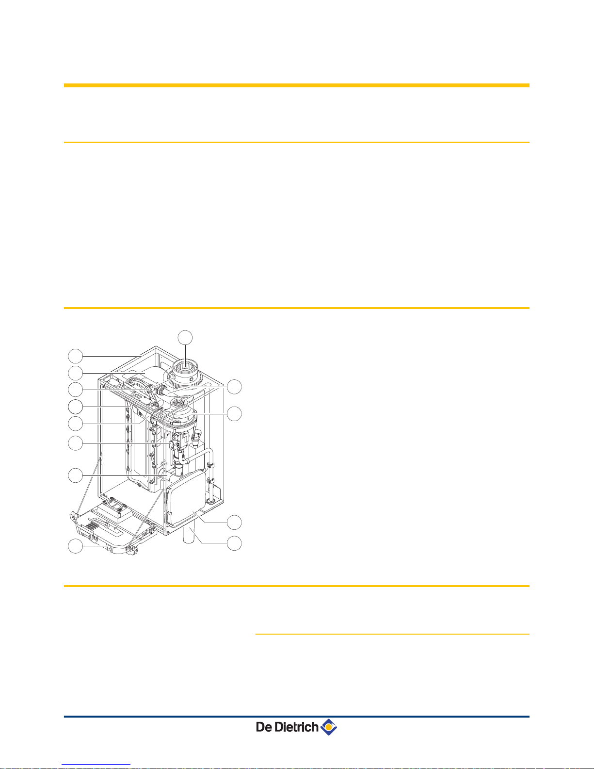
3.2 Main parts
1
Flue gas outlet / Air intake
2
Casing/air box
3
Heat exchanger (Central heating)
4
Outlet for measuring combustion gases
5
Ignition/ionization electrode
6
Mixer pipe
7
Combined venturi and gas valve unit
8
Áir intake silencer
9
Instrument box
10
Siphon
11
Box for the control PCBs
12
Fan
13
Water flow pipe
3.3 Operating principle
3.3.1. Shunt pump
The boiler is supplied without a pump. When choosing a pump, take
account of the boiler resistance and system resistance.
¼ See chapter: "Technical characteristics", page
13.
T002036-B
8
7
4
55
6
2
3
9
11
10
12
13
1
3. Technical description MCA 45 - 65 - 90 - 115
12
06/09/2010 - 300024755-001-A

If possible, install the pump directly under the boiler on the return
connection.
¼ See chapter: "Connection of the heating circuit", page
22.
CAUTION
The pump may have a maximum input of 200 W. Use an
auxiliary relay for a pump with a larger input.
3.3.2. System in cascade
The boiler is ideally suited for a cascade system. There are a number
of standard solutions available.
For example:
4 Cascade sets (quick assembly) for the installation of 2 to 7 boilers
next to each other or 3 to 10 boilers mounted back to back on a
free-standing frame. When the boilers are mounted next to each
other, they can be mounted either on the wall or on a free-standing
frame.
Please contact us for further information.
3.3.3. Calorifier connection
A calorifier can be connected to the boiler. Our product range includes
various calorifiers.
Please contact us for further information.
The calorifier can be connected to the boiler in two ways:
4 Using a three-way valve.
4 Using a calorifier pump.
3.3.4.
Water flow rate
The boiler's modulating control system limits the maximum difference
in
temperature between the heating flow and return and the maximum
speed at which the flow temperature increases. For this reason the
boiler is, so to speak, insensitive to a flow which is too low.
In all cases, maintain a minimum water flow of 0,4 m3/h.
3.4 Technical characteristics
MCA 45 - 65 - 90 - 115 3. Technical description
06/09/2010 - 300024755-001-A
13
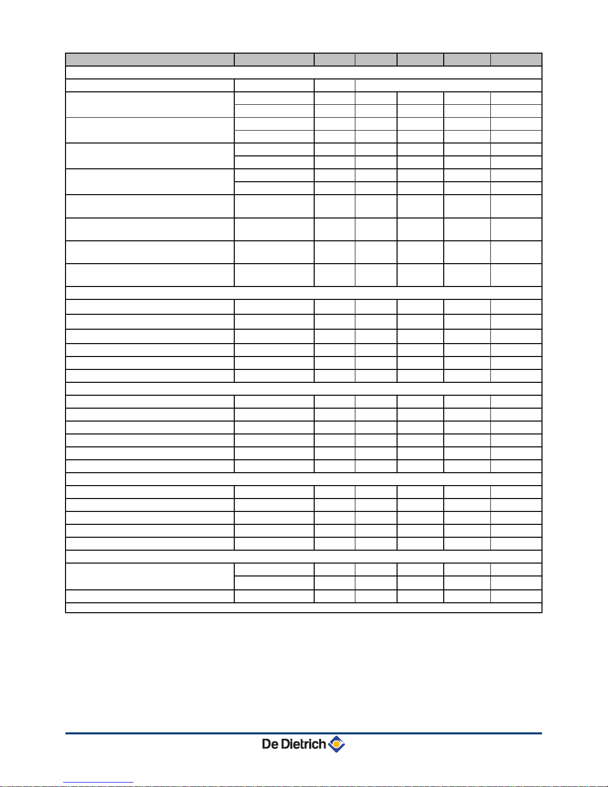
Boiler type
MCA 45 MCA 65 MCA 90 MCA 115
General
Flow rate setting Adjustable
Modulating, Start/Stop, 0 - 10 V
Nominal output (Pn)
Heating System (80/60 °C)
minimum-maximum kW 8,0 - 40,0 12,0 - 61,0 14,1 - 84,2 16,6 - 107,0
Factory setting kW 40,0 61,0 84,2 107,0
Nominal output (Pn)
Heating System (50/30 °C)
minimum-maximum kW 8,9 - 43,0 13,3 - 65,0 15,8 - 89,5 18,4 - 114,0
Factory setting kW 43,0 65,0 89,5 114,0
Nominal input (Qn)
Heating System (Hi)
minimum-maximum kW 8,2 - 41,2 12,2 - 62,0 14,6 - 86,0 17,2 - 110,2
Factory setting kW 41,2 62,0 86,0 110,2
Nominal input(Qn)
Heating System (Hs)
minimum-maximum kW 9,1 - 45,7 13,6 - 68,8 16,2 - 95,5 19,1 - 122,4
Factory setting kW 45,7 68,8 95,5 122,4
Heating efficiency under full load (Hi)
(80/60 °C)
- % 97,2 98,3 97,9 96,6
Heating efficiency under full load (Hi)
(50/30 °C)
- % 102,9 104,6 104,1 102,5
Heating efficiency under partial load (Hi)
(Return temperature 60
°C)
- % 97,5 98,3 96,6 96,5
Heating efficiency under partial load (EN
92/42)(Return temperature
30°C)
- % 107,7 108,9 108,1 107,1
Data on the gases and combustion gases
Gas consumption G20 (Natural gas H) minimum-maximum
m3/h
0,9 - 4,4 1,3 - 6,6 1,5 - 9,1 1,8 - 11,7
Gas consumption G31 (Propane) minimum-maximum
m3/h
0,3 - 1,7 0,5 - 2,5 0,6 - 3,5 0,6 - 4,7
NOx-Emission per year or (EN 483)
mg/kWh 37 32 45 46
Mass flue gas flow rate minimum-maximum Kg/h 14 - 69 21 - 104 28 - 138 36 - 178
Flue gas temperature minimum-maximum °C 30 - 67 30 - 68 30 - 68 30 - 72
Maximum counter pressure
Pa 150 100 160 220
Characteristics of the heating circuit
Water content
l 5,5 6,5 7,5 7,5
Water operating pressure minimum kPa (bar) 80 (0,8) 80 (0,8) 80 (0,8) 80 (0,8)
Water operating pressure (PMS) maximum kPa (bar) 400 (4,0) 400 (4,0) 400 (4,0) 400 (4,0)
Water temperature maximum °C 110 110 110 110
Operating temperature maximum °C 90 90 90 90
Water resistance (∆T = 20K)
mbar 90 130 140 250
Electrical characteristics
Power supply voltage
V/Hz 230/50 230/50 230/50 230/50
Power consumption - Full load maximum W 68 88 125 199
Power consumption - Part load maximum W 18 23 20 45
Power consumption - Standby maximum W 5 6 4 7
Electrical protection index
IP X4D X4D X4D X4D
Other characteristics
Weight (empty) Total kg 53 60 67 68
Mounting
(1)
kg 49 56 65 65
Acoustic level at 1 meter
dBA 45 45 52 51
(1) Front panel removed
3. Technical description MCA 45 - 65 - 90 - 115
14
06/09/2010 - 300024755-001-A
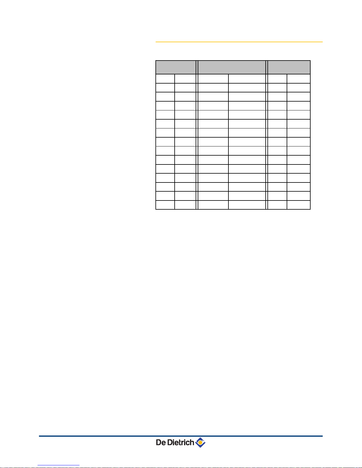
3.4.1. Sensor characteristics
Outside sensor Outlet sensor circuit B+C
Domestic hot water sensor
Boiler sensor
Return sensor
-20 °C
2392 ¨
0 °C
32014 ¨
-20 °C
98932 ¨
-16 °C
2088 ¨
10 °C
19691 ¨
-10 °C
58879 ¨
-12 °C
1811 ¨
20 °C
12474 ¨
0 °C
36129 ¨
-8 °C
1562 ¨
25 °C
10000 ¨
10 °C
22804 ¨
-4 °C
1342 ¨
30 °C
8080 ¨
20 °C
14773 ¨
0 °C
1149 ¨
40 °C
5372 ¨
25 °C
12000 ¨
4 °C
984 ¨
50 °C
3661 ¨
30 °C
9804 ¨
8 °C
842 ¨
60 °C
2535 ¨
40 °C
6652 ¨
12 °C
720 ¨
70 °C
1794 ¨
50 °C
4607 ¨
16 °C
616 ¨
80 °C
1290 ¨
60 °C
3252 ¨
20 °C
528 ¨
90 °C
941 ¨
70 °C
2337 ¨
24 °C
454 ¨
80 °C
1707 ¨
90 °C
1266 ¨
100 °C
952 ¨
110 °C
726 ¨
MCA 45 - 65 - 90 - 115 3. Technical description
06/09/2010 - 300024755-001-A
15
4 Installation
4.1 Regulations governing installation
WARNING
Installation of the appliance must be done by a qualified
engineer in accordance with prevailing local and national
regulations.
4.2 Package list
4.2.1. Standard delivery
The boiler is composed of 2 packages:
4 1 boiler package including:
- The boiler, fitted with a connection cable
- Mounting rail and mounting accessories for wall mounting
- Mounting template
- Installation and Service Manual
- User Guide
4 1 control panel package including:
- The DIEMATIC iSystem or IniControl control panel
- module assembly instructions
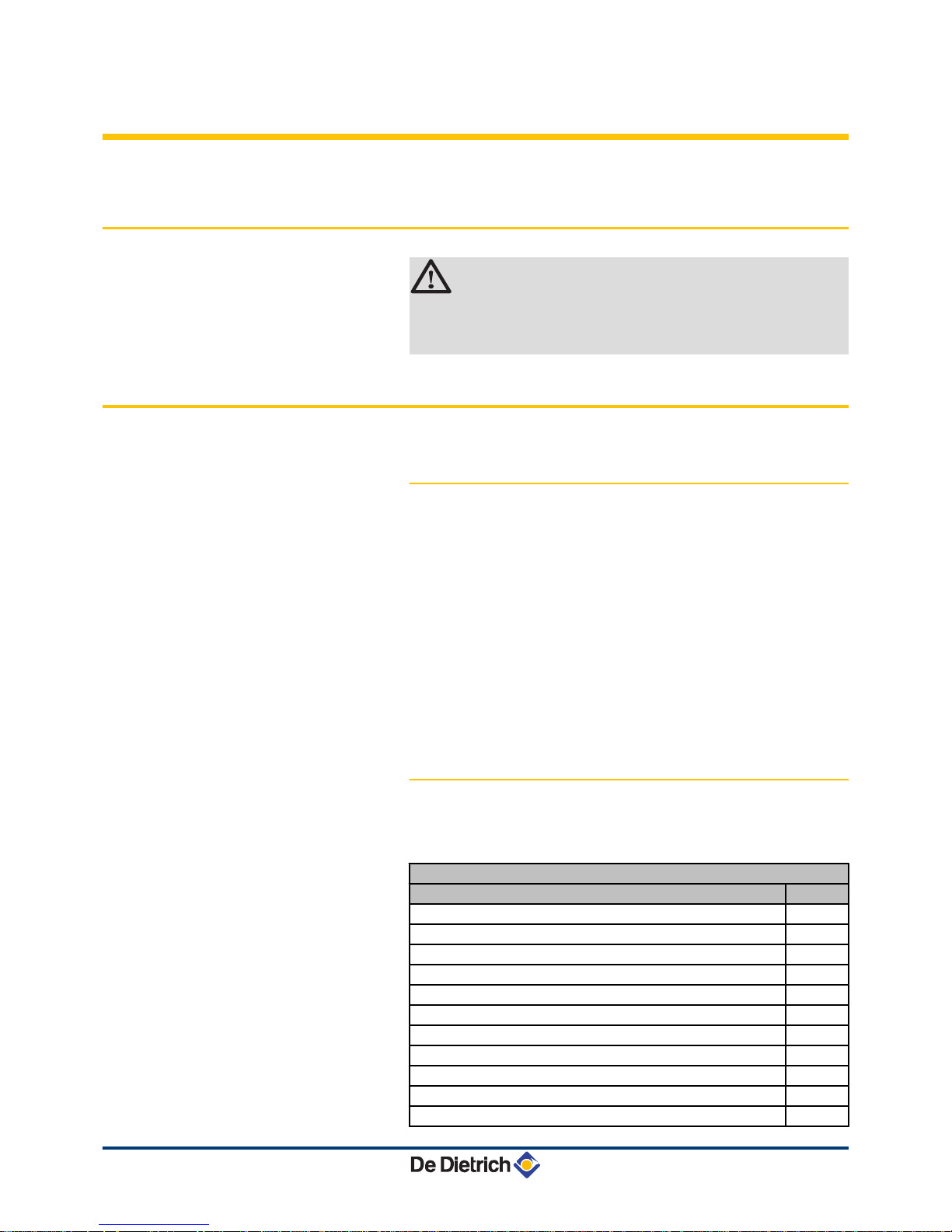
4.2.2.
Accessories
Various options are available depending on the configuration of the
installation:
Boiler options
Description package
Hydraulic connection kit - MCA 45 HC137
Hydraulic connection kit - MCA 65 / 90 / 115 HC139
Right gas valve 3/4" HC158
3-speed heating pump - MCA 45 HC141
Electronic heating pump - MCA 45 HC142
3-speed heating pump - MCA 65 HC143
3-speed heating pump - MCA 90 HC145
Primary pump - MCA 45 / 65 / 90 HC147
3-way valve with motor 1" HC15
Low loss header HW PLUS 70 HC28
Low loss header HW 200 HC29
4. Installation MCA 45 - 65 - 90 - 115
16
06/09/2010 - 300024755-001-A
Boiler options
Description package
Condensates neutralisation station HC33
Bracket for neutralisation station HC 33 HC34
2 kg refill of granulats to neutralisation station HC 33 HC35
Condensates neutralisation station (Boilers up to 120 kW) DU13
Condensates neutralisation station (Boilers from 120 to 350
kW)
DU14
Condensates neutralisation station (Boilers above 350 kW) DU15
Control system options
Description package
Optional PCB for 3-way valve Diematic iSystem AD249
System sensor AD250
Outside radio-controlled temperature sensor Diematic iSystem AD251
Boiler radio module AD252
Radio remote control Diematic iSystem AD253
Interactive remote control Diematic iSystem AD254
BUS connection cable (length 12 m) AD134
voice remote monitoring module AD152
Outlet sensor after 3-way valve AD199
A simplified remote control with room sensor FM52
Domestic hot water tank options
Description package
Heating / DHW inversion valve HC 134
Heating DHW reversal valve MCA 45 / 65 HC 135
Boiler/DHW tank connection kit BL / BP / BSC / DT EA 121
DHW sensor AD 212
MCA 45 - 65 - 90 - 115 4. Installation
06/09/2010 - 300024755-001-A
17
4.3 Choice of the location
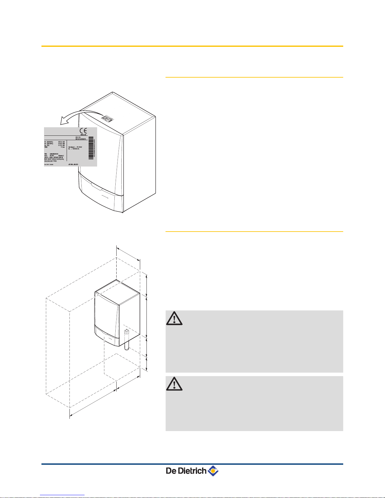
4.3.1. Data plate
The data plate located on top of the boiler provides important
information
on the appliance: serial number, model, gas category, etc.
4.3.2. Location of the appliance
4 Before mounting the boiler, decide on the ideal position for
mounting, bearing the Directives and the dimensions of the
appliance in mind.
4 When choosing the position for mounting the boiler, bear in mind
the authorised position of the combustion gas discharge outlets
and the air intake opening.
4 To ensure adequate accessibility to the appliance and facilitate
maintenance, leave enough space around the boiler.
WARNING
4 Fix the appliance to a solid wall capable of bearing
the weight of the appliance when full of water and fully
equipped.
4 It is forbidden to store inflammable products and
materials in the boiler room or close to the boiler,
even temporarily.
CAUTION
4 The boiler must be installed in a frost-free
environment.
4 A connection to the mains drainage system for the
discharge of condensate must be available close to
the boiler.
T001982-A
T002599-B
500
min.1000
500
min.
400
350
min.
250
750
4. Installation MCA 45 - 65 - 90 - 115
18
06/09/2010 - 300024755-001-A
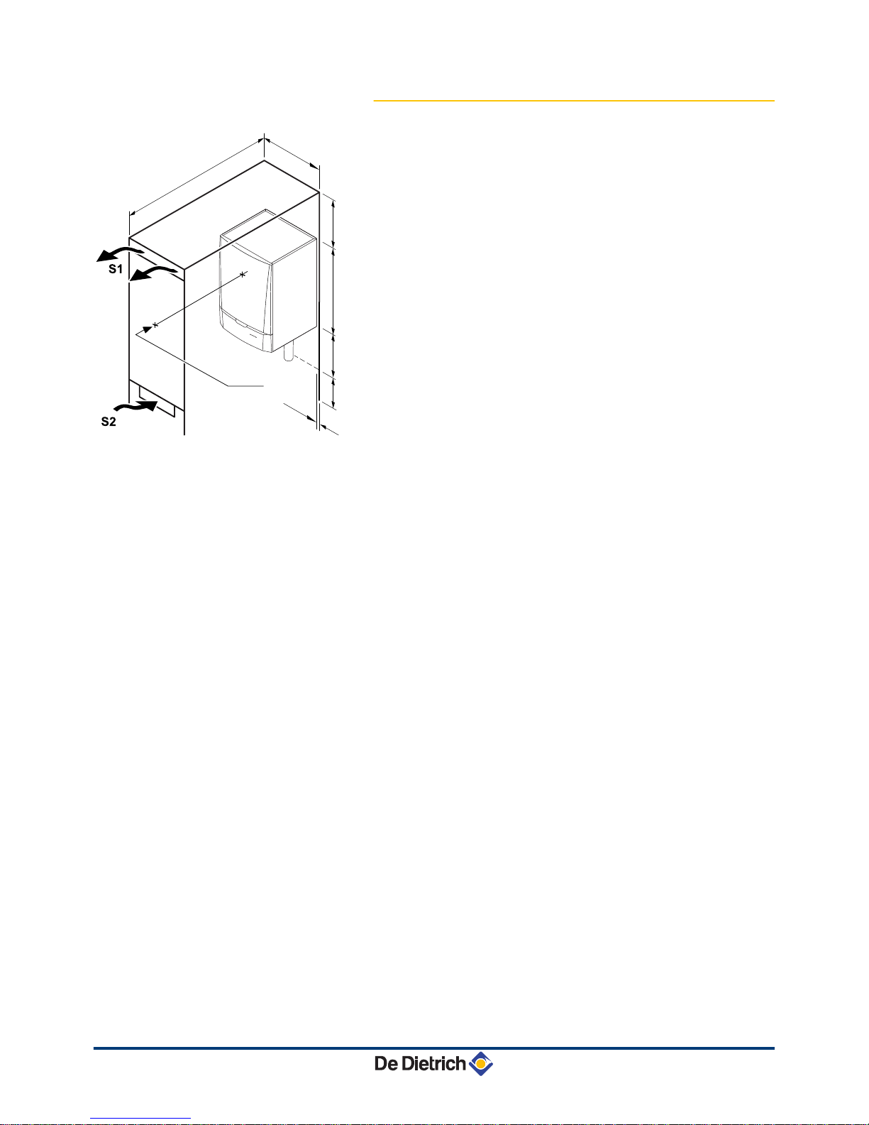
4.3.3. Ventilation
(1)
Distance between the front of the appliance and the
internal wall of the cupboard.
(2)
Distance to allow on either side of the appliance.
If the boiler is installed in a closed box, respect the minimum
dimensions given in the diagram opposite. Also allow openings to
obviate the following hazards:
4 Accumulation of gas
4 Heating of the box
Minimum cross section of the openings: S1 + S2 = 150 cm
2
T002600-B
1000
min. (1)
530
15 (2)
min.1500
min.
400
min.
250
750
350
MCA 45 - 65 - 90 - 115 4. Installation
06/09/2010 - 300024755-001-A
19
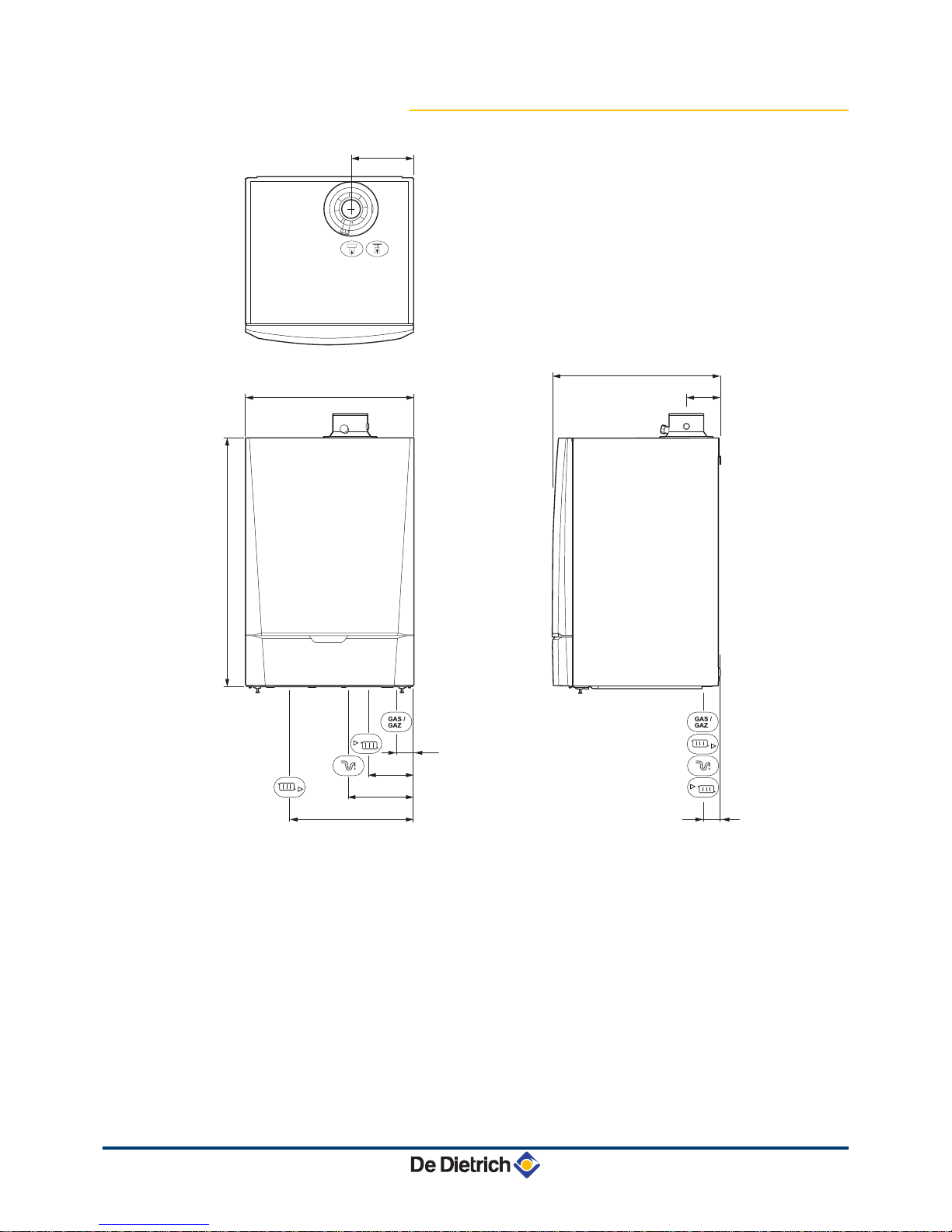
4.3.4. Main dimensions
i
Connection of the combustion gas exhaust pipe ;
Ø 80 mm (≤ 45 kW) /
Ø 100 mm (≥ 65 kW)
h
Connection of the air intake pipe ;
Ø 125 mm (≤ 45 kW) / Ø
150 mm (≥ 65 kW)
â
Siphon connection bush
z
Heating circuit return ; 1 ¼" Male thread
Gas /
Gaz
Gas connection ; ¾" Male thread
{
Heating circuit flow ; 1 ¼" Male thread
T002614-C
191
500
750
500
100
50
50
130
191
365
4. Installation MCA 45 - 65 - 90 - 115
20
06/09/2010 - 300024755-001-A
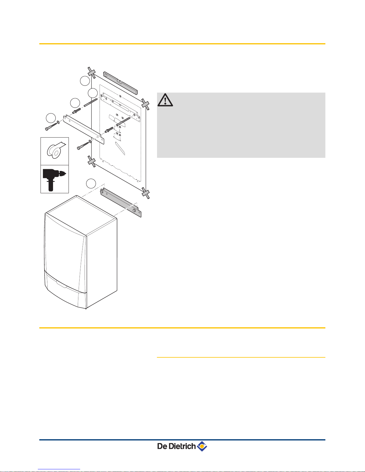
4.4 Positioning the boiler
The boiler is delivered with a mounting template.
A suspension clamp situated at the rear of the casing enables the
boiler to be directly suspended on the mounting bracket.
1.
Position the mounting template to the wall with adhesive tape.
CAUTION
4 Using a spirit level, check that the mounting axis is
perfectly horizontal.
4 During mounting, cover up the connection points for
the air supply and the combustion gas exhaust, to
protect
the boiler and its connections from dust. Only
remove this protection at the time when these
connections are made.
2. Drill 2 holes with a Ø of 10 mm.
3.
Insert the rawplugs with a Ø of 10 mm.
4. Attach the mounting bracket to the wall with the provided bolts with
a Ø of 10 mm.
5. Hang the boiler on the mounting bracket.
4.5 Hydraulic connections
4.5.1. Flushing the system
Installation must be carried out in accordance with the prevailing
regulations,
the codes of practice and the recommendations in these
instructions.
T001540-A
2
1
5
4
3
MCA 45 - 65 - 90 - 115 4. Installation
06/09/2010 - 300024755-001-A
21
n
Installing the boiler in new installations (installations
less than 6 months old)
4 Clean the installation with a universal cleaner to eliminate debris
from the appliance (copper, flaxen thread, flux).
4 Thoroughly flush the installation until the water runs clear and
shows no impurities.
n
Installing the boiler in existing installations
4 Remove sludge from the installation.
4 Flush the installation.
4 Clean the installation with a universal cleaner to eliminate debris
from the appliance (copper, flaxen thread, flux).
4 Thoroughly flush the installation until the water runs clear and
shows no impurities.
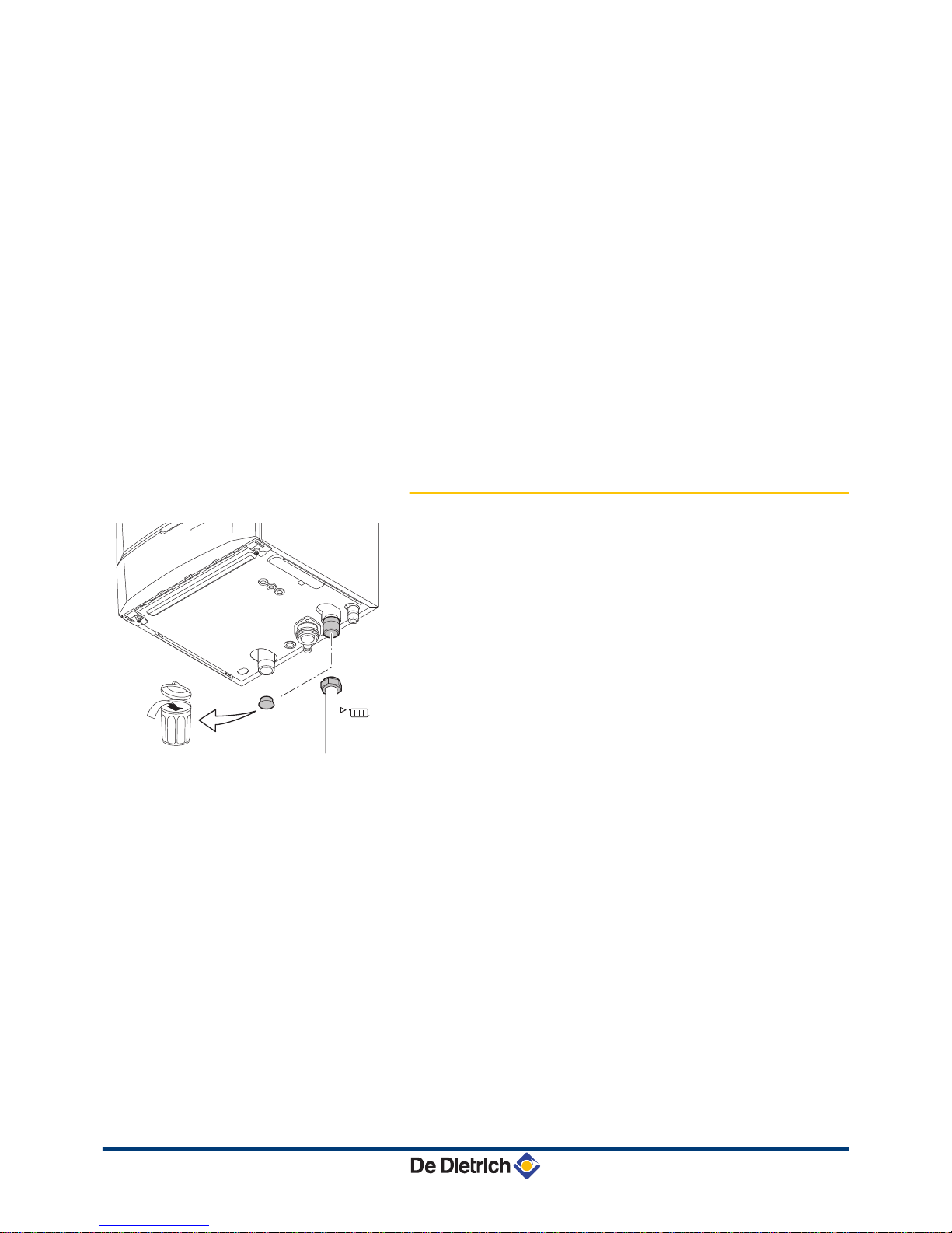
4.5.2.
Connection of the heating circuit
1. Remove the anti-dust plug located on the heating outlet
connection { under the boiler.
2.
Connect the heating water outlet pipe to the heating flow
connection.
3. Install a filling and drainage valve on the installation for filling and
draining the boiler.
T002856-C
4. Installation MCA 45 - 65 - 90 - 115
22
06/09/2010 - 300024755-001-A
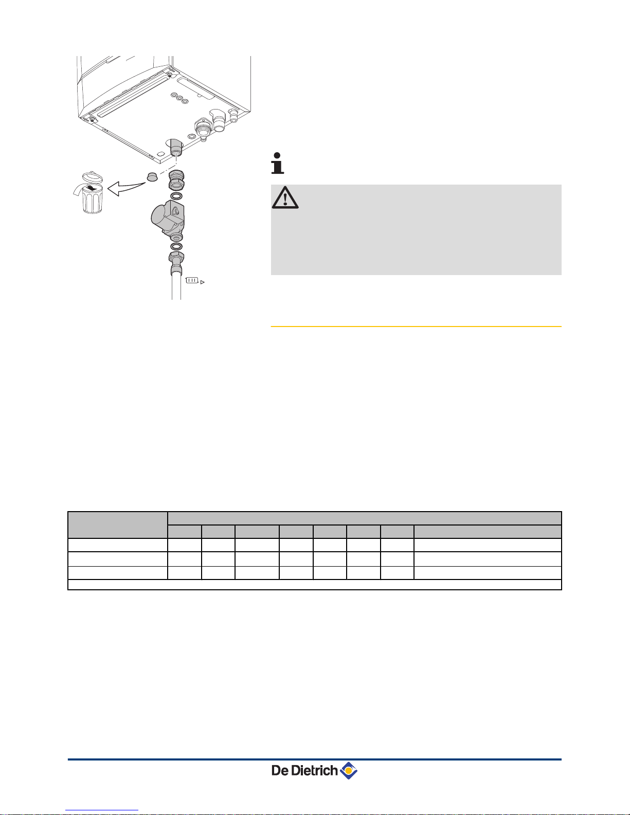
4. Remove the anti-dust button located on the heating return
connection z under the boiler.
5.
Connect the heating water return pipe to the heating return
connection.
6. Fit the pump in the return pipe.
¼
For the electrical connection of the pump, see chapter:
"Connecting the pump", page 32
To facilitate maintenance work, we recommend mounting
a shut off valve on the heating flow and return pipes.
CAUTION
4 The heating pipe must be mounted in accordance
with prevailing provisions.
4 If installing shut off valves, position the filling/
drainage valve and the expansion vessel between
the shut off valves and the boiler.
4.5.3. Connecting the expansion vessel
Install the expansion vessel on the heating return pipe z.
Refer to the table below to determine the opened expansion vessel
required for the installation.
Conditions of validity of the table:
4 3-bar safety valve
4 Average water temperature:
70 °C
Flow temperature: 80 °C
Return temperature: 60 °C
4 The filling pressure in the system is lower than or equal to the initial
pressure in the opened expansion vessel
Initial pressure of the
expansion vessel
Volume of the opened expansion vessel depending on the volume of the installation (in litres)
100 125 150 175 200 250 300 > 300
0.5 bar 4,8 6,0 7,2 8,4 9,6 12,0 14,4 Volume of the installation x 0,048
1 bar 8,0 10,0
12,0
(1)
14,0 16,0 20,0 24,0 Volume of the installation x 0,080
1.5 bar 13,3 16,6 20,0 23,3 26,6 33,3 39,9 Volume of the installation x 0,133
(1) Factory configuration
T002857-B
MCA 45 - 65 - 90 - 115 4. Installation
06/09/2010 - 300024755-001-A
23
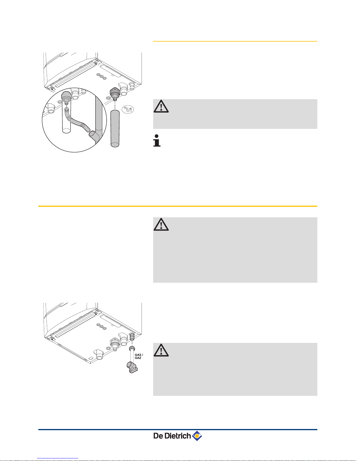
4.5.4. Connecting
the condensate discharge pipe
1. Fit
the condensate drain hose and the syphon of the boiler: these
are supplied separately.
2. Mount a standard drainage pipe, Ø 32 mm or more, leading to the
mains drainage system.
3.
Insert into this the hose of the condensate drain â.
4. Mount a trap or a siphon in the discharge pipe.
CAUTION
Do not make a fixed connection owing to maintenance
work on the siphon.
4 Do not plug the condensate discharge pipe.
4 Set the discharge pipe at a gradient of at least
30
mm per metre, maximum horizontal length 5 metres.
4 Do not drain condensation water into a roof gutter at
any time.
4 Connect the condensate discharge pipe in
accordance with prevailing standards.
4.6 Gas connection
WARNING
4 Close
the main gas valve before starting work on the
gas pipes.
4 Before mounting, check that the gas meter has
sufficient capacity. To do this, you should keep in
mind the consumption of all appliances.
4 If the gas meter has too low a capacity, inform the
energy supply company.
The diameters of the pipes must be defined in accordance with the
standards in force in your country.
1. Remove
the anti-dust plug from the GAS/GAZ gas inlet pipe under
the boiler.
2. Connect the gas inlet pipe.
3. Mount a gas isolation valve on this pipe, directly under the boiler.
4. Connect the gas pipe to the gas shut off valve.
CAUTION
4 Ensure that there is no dust in the gas pipe.
4 We
recommend installing a gas filter on the gas pipe
to prevent clogging of the gas valve unit.
4 Connect the gas pipe in accordance with prevailing
standards and regulations.
T002858-B
T002859-C
4. Installation MCA 45 - 65 - 90 - 115
24
06/09/2010 - 300024755-001-A
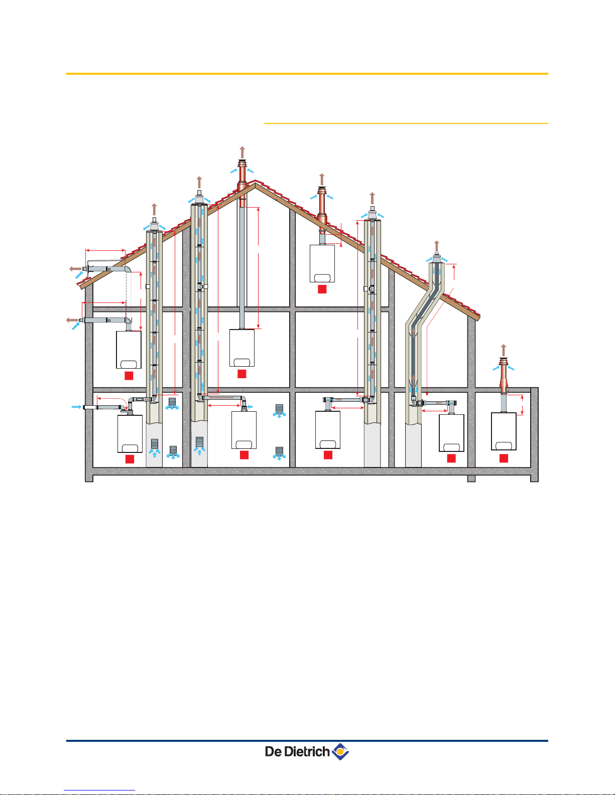
4.7 Flue gas system connections
4.7.1. Classification
6 3
4 2
2
2
1
5
L1
L1
Lmax = L1+L2
Lmax =
L
1+L2
Lmax
Lmax
Lmax
Lmax
max
max
max
1m
1m
1m
Lmax
L2
L2
Lmax
Lmax
C
33
C
93
B
23
C
93
C
33
C
33
C
13
C
53
C003034-A
1
Configuration C
13
Air/flue
gas connection by means of concentric pipes to a
horizontal terminal (so-called forced flue)
2
Configuration C
33
Air/flue
gas connection by means of concentric pipes to a
vertical terminal (roof outlet)
3
Configuration C
93
Air/flue gas connection by concentric pipes in the boiler
room and single pipes in the chimney (combustive air in
counter current in the chimney)
MCA 45 - 65 - 90 - 115 4. Installation
06/09/2010 - 300024755-001-A
25
4
Configuration C
93
Air/flue gas connection by concentric pipes in the boiler
room and single "flex" in the chimney (combustive air in
counter current in the chimney)
WARNING
4 Only
factory components are authorised for
connecting the boiler and the terminal.
4 The clear section must comply with the
standard.
4 The chimney must be swept before the
installation of the evacuation conduit.
5
Configuration C
53
Air and flue gas connection separated by means of a biflow
adapter and single pipes (combustive air taken from
outside)
6
Configuration B
23
Connection to a chimney using a connection kit
(combustive air taken from the boiler room
)
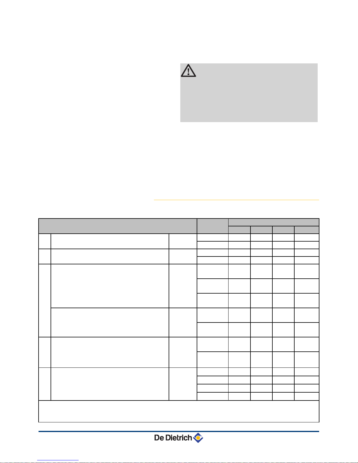
4.7.2. Lengths of the air/flue gas pipes
Type of air/flue gas connection Diameter Maximum length
MCA 45 MCA 65 MCA 90 MCA 115
C13Concentric pipes connected to a horizontal terminal Alu or PPS 80/125 mm 16 m - - -
100/150 mm - 9 m 8 m 5,9 m
C33Concentric pipes connected to a vertical terminal aluminium 80/125 mm 14,5 m - - -
100/150 mm - 11,5 m 10 m 9,4 m
C93Concentric pipes in the boiler room
Single conduits in the chimney (combustive air in
counter-current)
aluminium 80/125 mm
80 mm
15 m - - -
80/125 mm
100 mm
11,5 m - - -
110/150 mm
110 mm
- 11 m 12,5 m 10 m
Concentric pipes in the boiler room
Single
flexible pipe in the chimney (combustive air in
counter-current)
PPS 80/125 mm
80 mm
12 m - - -
110/150 mm
110 mm
- 16,5 m 13,5 m 9,4 m
C53Bi-flow adapter and separate single air/flue gas ducts
(combustive air taken from outside)
aluminium 80/125 mm
2 x 80 mm
20,5 m - - -
100/150 mm
2 x 100 mm
- 23 m 17,5 m
11 m
(1)
5 m
(2)
B23Chimney (rigid or flexible duct in furnace flue,
combustive air taken from the premises)
PPS
80 mm
(3)
23,5 m - - -
110 mm
(3)
- 55 m 45 m 44 m
80 mm
(4)
21 m - - -
110 mm
(4)
- 29,5 m 24 m 17,5 m
(1) Air
(2)
Flue gases
(3) Rigid duct
(4) Flexible duct
4. Installation MCA 45 - 65 - 90 - 115
26
06/09/2010 - 300024755-001-A
WARNING
Maximum length = lengths of the straight air/flue gas ducts
+ equivalent lengths of other components
For the list of flue gas system accessories and the equivalent lengths,
refer to the current price list.
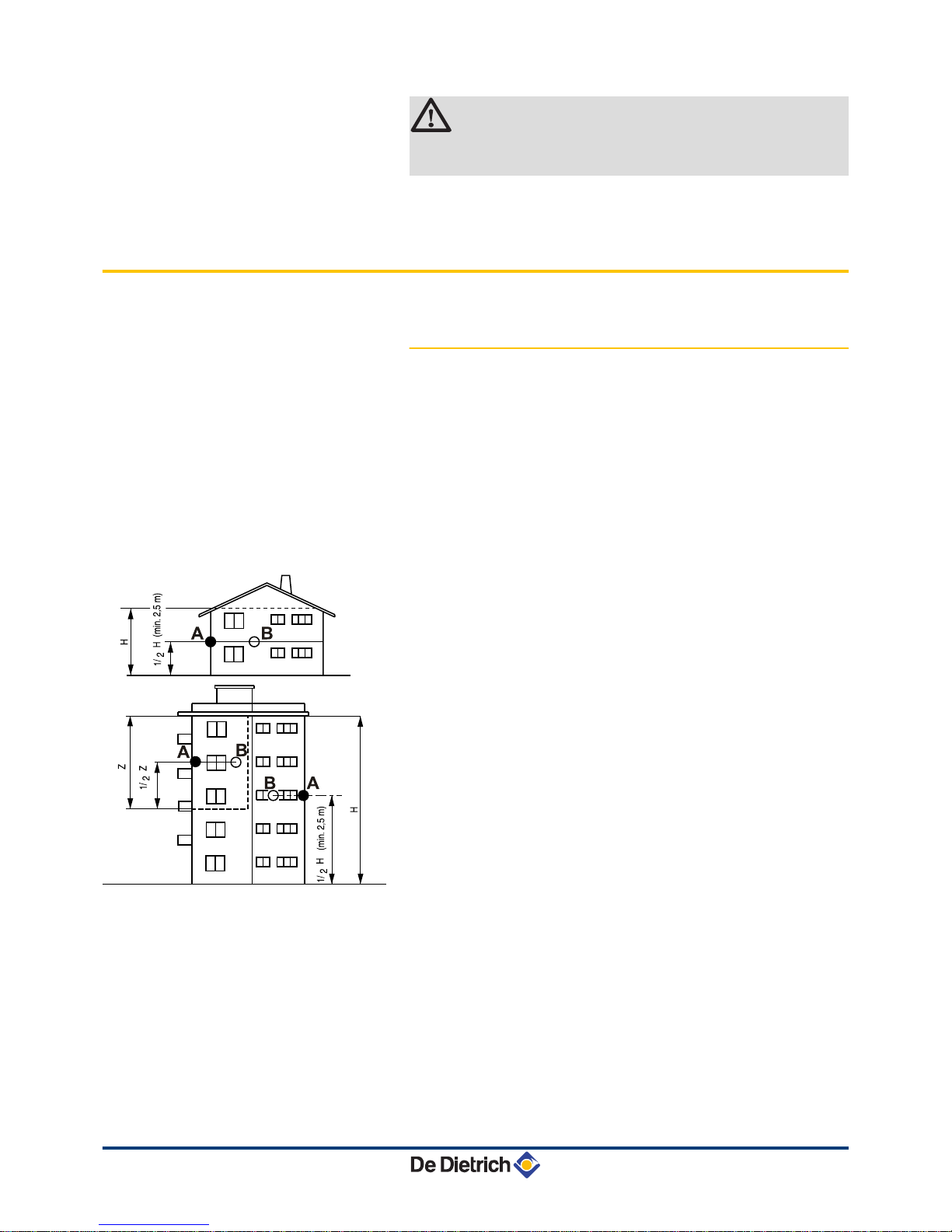
4.8
Installing the outside sensor
4.8.1. Choice of the location
It is important to select a place that allows the sensor to measure the
outside conditions correctly and effectively.
Advised positions:
4 on one face of the area to be heated, on the north if possible
4 half way up the wall in the room to be heated
4 under the influence of meteorological variations
4 protected from direct sunlight
4 easy to access
A
Recommended position
B
Possible position
H
Inhabited height controlled by the sensor
Z
Inhabited area controlled by the sensor
8800N001-C
MCA 45 - 65 - 90 - 115 4. Installation
06/09/2010 - 300024755-001-A
27
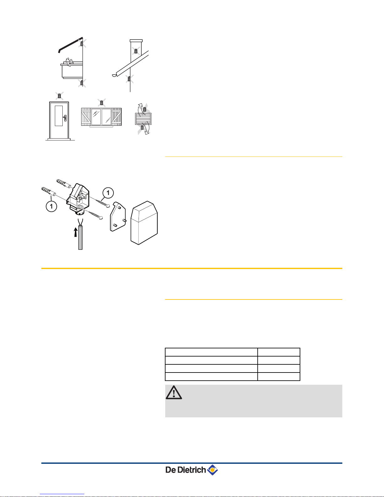
Positions to be avoided:
4 masked by a building element (balcony, roof, etc.)
4 close to a disruptive heat source (sun, chimney, ventilation grid,
etc.)
4.8.2. Installing the outside sensor
Mount the sensor using the screws and dowels provided.
A
CB wood screws diameter 4 + dowels
4.9 Electrical connections
4.9.1. Control unit
The boiler is fully pre-wired. The mains supply is made via the cable
C
connected to the mains. All other external connections can be made
to the connection connectors (low voltage). The main characteristics
of the control unit are described in the table below.
Power supply voltage
230 V AC/50 Hz
Rating of the main fuse F1(230 V AC) 6.3 AT
Fuse rating F2(230 V AC) 2 AT
Fan 230 V AC
CAUTION
Keep to the polarity shown on the terminals: phase (L),
neutral (N) and earth *.
8800N002-C
8800N003-B
4. Installation MCA 45 - 65 - 90 - 115
28
06/09/2010 - 300024755-001-A

A
Routing of the 230 V cables
B
Power supply cable
C
Cable of housing for control PCBs
D
6,3 AT fuse
E
2 AT fuse
CAUTION
The following components of the appliance are at a
voltage of 230 V:
4 Electrical connection of the heating pump
(Central
heating).
4 Electrical connection of the combined gas valve unit.
4 Electrical connection of the fan.
4 The majority of components in the control panel.
4 Most parts of the housing for control PCBs.
4 Ignition transformer.
4 Connection of the power supply cable.
4.9.2. Recommendations
WARNING
4 Only
qualified professionnals may carry out electrical
connections, always with the power off.
4 The boiler is entirely pre-wired. Do not modify the
connections inside the control panel.
4 Earth the appliance before making any electrical
connections.
Make the electrical connections of the appliance according to:
4 the instructions of the prevailing standards.
4 the instructions on the circuit diagrams provided with the
appliance.
4 the recommendations in the instructions.
CAUTION
4 Separate the sensor cables from the 230 V cables.
4 Outside the boiler: Use 2 pipes or cable guides at
least 10 cm apart.
T002039-A
ED
B
A
X2
C
C
MCA 45 - 65 - 90 - 115 4. Installation
06/09/2010 - 300024755-001-A
29

4.9.3. Fitting and connecting the control panel
1. Unscrew the 2 screws under the front panel by a quarter turn.
2.
Remove the front panel.
3. Fit and connect the control panel.
¼
To fit and connect the control panel, see the brochure
delivered in the control panel package.
4.9.4. Position of the PCBs
T001999-A
SCU PCU
N
TS + CC
LN N L
AUX
N
TS + BB
LN L N
Alim
230 V - 50 Hz
L
N N L
A
TdhwToutRLBLOT
On/off
1
2
3
2
S SYST
1 2
+ S ECS S EXTTA - S DEP C S DEP B
1 2 1 2 1 2 1 2 1
+
0-10V
- 4
S CAMB S AMBB S AMPA
3 2 1 2 1 2 1 2 1
PCU
SU
SCU
PSU
C002912-A
2
1
90º
4. Installation MCA 45 - 65 - 90 - 115
30
06/09/2010 - 300024755-001-A

A
Do not connect anything to the terminal block.
Z
Optional PCB (Package AD249)
E
Do not connect anything to the terminal block.
4.9.5. Accessing the connection terminal blocks
To access the connection terminal blocks, proceed as follows:
1.
Unscrew the 2 screws under the front panel by a quarter turn.
2. Remove the front panel.
3. Tilt the control box forwards by opening the holding clips located
at the sides.
4. Open the tooling box by opening the clip fastener on the front side.
5. Lift the control panel cover.
T001514-A
2
1
90º
T001991-A
2
1 1
T002040-A
MCA 45 - 65 - 90 - 115 4. Installation
06/09/2010 - 300024755-001-A
31

6. Unclip the PCB cover.
4.9.6.
Connecting the pump
The pump must be connected to standard control PCB (PCU).
To do
this, proceed as follows:
1. Connect the cable, that is delivered with the boiler, to the pump.
T002862-A
2
x3
1
T002047-B
X81
X81
4. Installation MCA 45 - 65 - 90 - 115
32
06/09/2010 - 300024755-001-A

2. Remove the grommet from the opening in the middle of the base
of
the boiler. Pass the pump connection cable through the base of
the boiler and seal the opening again by tightening the bayonet
fitting to the cable.
3. Connect the pump connection cable to the cable in the instrument
box that is connected with connector X8.
T002048-A
1
2
3
T002050-C
X8
X81
X81
MCA 45 - 65 - 90 - 115 4. Installation
06/09/2010 - 300024755-001-A
33

4. Connect the pump connection cable to the cable bundle by
opening and closing the cable bundle bands.
4.9.7.
Connecting a direct heating circuit
C002903-B
2
4
3
On/off
OT BL RL Tout Tdhw
1
TS + B AB
0-10V
S AMB C
4 3 2 1 2 1
+ -
S AMB B
2 1
S AMB A
2 1
S SYST + TA -
S ECS S EXT S DEP C
2 12 12 12 1 2 1
S DEP B
2 1
SCU PCU
5
A
Do not connect anything to the terminal block.
Z
Connect the outside temperature sensor.
E
Heating connection pump.
T002049-B
4. Installation MCA 45 - 65 - 90 - 115
34
06/09/2010 - 300024755-001-A

R
Connect a safety thermostat if the heating circuit is for
underfloor heating.
4 Remove the bridge.
4 Connect the wires from the safety thermostat to the
connector.
T
Do not connect anything to the terminal block.
4.9.8. Connecting a direct heating circuit and a
domestic hot water tank
C002904-B
6
4
5
7
8
9
2
3
On/off
OT BL RL Tout Tdhw
1
TS + B AB
0-10V
S AMB C
4 3 2 1 2 1
+ -
S AMB B
2 1
S AMB A
2 1
S SYST + TA -
S ECS S EXT S DEP C
2 12 12 12 1 2 1
S DEP B
2 1
SCU PCU
TS + C AUXC
A
Do not connect anything to the terminal block.
Z
Domestic load pump connection
E
Connect the heating pump
R
Connect a safety thermostat if the heating circuit is for
underfloor heating.
4 Remove the bridge.
4 Connect the wires from the safety thermostat to the
connector.
MCA 45 - 65 - 90 - 115 4. Installation
06/09/2010 - 300024755-001-A
35

T
Connect the DHW tank anode.
CAUTION
4 If the tank is fitted with a Titan Active
System® impressed current anode,
connect the anode to the inlet (+ on the
anode, - on the tank).
4 If the tank is not fitted with an impressed
current anode, put the simulation
connector
in place (delivered with the DHW
sensor - package AD212).
Y
Connect the outside temperature sensor.
U
Connect the DHW sensor (Package AD212).
I
Connect the domestic hot water looping pump
(Optional).
O
Do not connect anything to the terminal block.
DIEMATIC iSystem - Settings to be made for this type of installation
Parameters Access Settings to be made See
INSTALLATION
"Installer" level
#SYSTEM menu
EXTENDED
¼
"Displaying the parameters
in extended mode", page 65
If a domestic hot water looping pump
is connected to MAUX on the
terminal block:
O.PUMP AUX
(1)
"Installer" level
#SYSTEM menu
DHW LOOP
¼ "Setting the parameters
specific to the installation", page
66
If safety thermostat is connected to
BL on the connection terminal block:
IN.BL
"Installer" level
#PRIMARY INSTAL.P
menu
TOTAL STOP
¼ ""Professional" settings",
page 75
If a DHW tank (type BS60) is
connected
(2)
"Installer" level
#SYSTEM menu
ON
¼ "Setting the parameters
specific to the installation", page
66
(1) The parameter is only displayed if INSTALLATION parameter is set to EXTENDED
(2)
The parameter is only displayed if INSTALLATION parameter is set to EXTENDED
IniControl - Settings to be made for this type of installation
No further adjustments are necessary
4.9.9. Connecting
two circuits and a domestic hot
water tank after the mixing tank
This configuration is only possible with the DIEMATIC
iSystem control panel.
4. Installation MCA 45 - 65 - 90 - 115
36
06/09/2010 - 300024755-001-A

C002905-B
7
8
11
10
6
5
1
2
4
9
3
12
On/off
OT BL RL Tout Tdhw
TS + B AB
0-10V
S AMB C
4 3 2 1 2 1
+ -
S AMB B
2 1
S AMB A
2 1
S SYST + TA -
S ECS S EXT S DEP C
2 12 12 12 1 2 1
S DEP B
2 1
TS + C AUXC
SCU PCU
A
Do not connect anything to the terminal block.
Z
Connect a safety thermostat if the heating circuit is for
underfloor heating.
4 Remove the bridge.
4 Connect the wires from the safety thermostat to the
connector.
E
Connecting an additional circuit to the AD249 option.
R
Connect the heating pump (circuit A).
If underfloor heating is being used, put a safety
thermostat in place after the heating pump.
The
safety thermostat will shut down the heating
pump in the event of overheating.
MCA 45 - 65 - 90 - 115 4. Installation
06/09/2010 - 300024755-001-A
37

T
Connect the DHW tank anode.
CAUTION
4 If the tank is fitted with a Titan Active
System® impressed current anode,
connect the anode to the inlet (+ on the
anode, - on the tank).
4 If the tank is not fitted with an impressed
current anode, put the simulation
connector
in place (delivered with the DHW
sensor - package AD212).
Y
Connect the outside temperature sensor.
U
Connect the heating pump (circuit B).
I
Connect the 3-way valve (circuit B).
O
Domestic load pump connection.
P
Connect the DHW sensor (Package AD212).
a
Connect the domestic hot water looping pump to the
MAUX outlet on the AD249 option.
z
Do not connect anything to the terminal block.
4.9.10. Hot water storage tank connection
This configuration is only possible with the DIEMATIC
iSystem control panel.
n
QUADRO DU storage tank
In this installation example, the storage tank (type
QUADRO DU)
incorporates a domestic hot water zone. The boiler starts up
systematically to maintain the domestic hot water zone in the storage
tank or to maintain the independent tank at temperature.
If the storage tank does not have a DHW zone, use an
independent domestic hot water tank.
4. Installation MCA 45 - 65 - 90 - 115
38
06/09/2010 - 300024755-001-A

C002906-B
On/off
OT BL RL Tout Tdhw
TS + B AB
0-10V
S AMB C
4 3 2 1 2 1
+ -
S AMB B
2 1
S AMB A
2 1
S SYST + TA -
S ECS S EXT S DEP C
2 12 12 12 1 2 1
S DEP B
2 1
SCU PCU
6
3
2
4
9
8
5
7
1
10
M
X81
A
Do not connect anything to the terminal block.
Z
Connect the load pump from the buffer tank.
E
Connect the sensor from the storage tank (Package
AD250).
R
Buffer tank.
T
Connect the DHW tank anode.
If the tank is not fitted with an impressed current
anode, put the simulation connector in place
(delivered with the DHW sensor - package
AD212).
Y
Connect the DHW sensor (Package AD212).
U
Connect the heating pump (Circuit A).
I
Solar sensor probe.
O
Connect the solar station to the solar collectors.
P
Do not connect anything to the terminal block.
MCA 45 - 65 - 90 - 115 4. Installation
06/09/2010 - 300024755-001-A
39

DIEMATIC iSystem - Settings to be made for this type of installation
Parameters Access Settings to be made See
INSTALLATION
"Installer" level
#SYSTEM menu
EXTENDED
¼
"Displaying the parameters in extended mode", page
65
I.SYST
(1)
"Installer" level
#SYSTEM menu
STORAGE TANK
¼ "Setting the parameters specific to the installation",
page 66
(1) The parameter is only displayed if INSTALLATION parameter is set to EXTENDED
The DHW part is maintained at the DHW set point by the
boiler.
The heating zone is maintained at the set temperature
calculated
according to the outside temperature. The zone
is reheated when the heating buffer temperature sensor
E falls -6°C below the calculated set temperature.
Reheating in the heating zone stops when the heating
buffer temperature rises above the calculated set
temperature.
4. Installation MCA 45 - 65 - 90 - 115
40
06/09/2010 - 300024755-001-A

n
PS storage tank and DHW tank connected to the boiler
5
2
3
1
C002907-B
10
On/off
OT BL RL Tout Tdhw
TS + B AB
0-10V
S AMB C
4 3 2 1 2 1
+ -
S AMB B
2 1
S AMB A
2 1
S SYST + TA -
S ECS S EXT S DEP C
2 12 12 12 1 2 1
S DEP B
2 1
SCU PCU
4
7
8
11
12
6
9
X81
A
Do not connect anything to the terminal block.
Z
D.H.W. load pump
E
Buffer tank load pump.
R Connect a domestic hot water tank if the storage tank O
is only used for heating
T
Connect the DHW sensor (Package AD212).
Y
Connect the DHW tank anode.
If the tank is not fitted with an impressed current
anode, put the simulation connector in place
(delivered with the DHW sensor - package
AD212).
U
Connect the heating pump (Circuit A).
MCA 45 - 65 - 90 - 115 4. Installation
06/09/2010 - 300024755-001-A
41

I
Solar sensor probe.
O
Buffer tank.
P
Do not connect anything to the terminal block.
a
Connect the solar station to the solar collectors.
z
Solar sensor probe
DIEMATIC iSystem - Settings to be made for this type of installation
Parameters Access Settings to be made See
INSTALLATION
"Installer" level
#SYSTEM menu
EXTENDED
¼
"Displaying the parameters in extended mode", page
65
I.SYST
(1)
"Installer" level
#SYSTEM menu
STORAGE TANK
¼ "Setting the parameters specific to the installation",
page 66
(1) The parameter is only displayed if INSTALLATION parameter is set to EXTENDED
The DHW part is maintained at the DHW set point by the
boiler.
The heating zone is maintained at the set temperature
calculated
according to the outside temperature. The zone
is reheated when the heating buffer temperature sensor
falls -6°C below the calculated set temperature. Reheating
in the heating zone stops when the heating buffer
temperature rises above the calculated set temperature.
4. Installation MCA 45 - 65 - 90 - 115
42
06/09/2010 - 300024755-001-A

n
PS
storage tank and DHW tank connected to the storage
tank
The boiler only starts up production of domestic hot water if the
storage tank is not hot enough to guarantee tank loading.
C002908-A
4
7
6
2
3
1
5
9
8
On/off
OT BL RL Tout Tdhw
TS + B AB
0-10V
S AMB C
4 3 2 1 2 1
+ -
S AMB B
2 1
S AMB A
2 1
S SYST + TA -
S ECS S EXT S DEP C
2 12 12 12 1 2 1
S DEP B
2 1
SCU PCU
A
Do not connect anything to the terminal block.
Z
Connect the heating pump (Circuit A).
E
Buffer tank load pump
R
Connect the DHW tank anode.
If the tank is not fitted with an impressed current
anode, put the simulation connector in place
(delivered with the DHW sensor - package
AD212).
T
Buffer tank.
Y
Solar sensor probe.
U
Connect the solar station to the solar collectors.
MCA 45 - 65 - 90 - 115 4. Installation
06/09/2010 - 300024755-001-A
43

I
Domestic hot water boiler.
Connect the DHW sensor.
O
Do not connect anything to the terminal block.
DIEMATIC iSystem - Settings to be made for this type of installation
Parameters Access Settings to be made See
INSTALLATION
"Installer" level
#SYSTEM menu
EXTENDED
¼
"Displaying the parameters in extended mode", page
65
I.SYST
(1)
"Installer" level
#SYSTEM menu
ST.TANK+DHW
¼ "Setting the parameters specific to the installation",
page 66
(1) The parameter is only displayed if INSTALLATION parameter is set to EXTENDED
The DHW tank is loaded from the storage tank. If, during
DHW loading, the temperature of the storage tank falls
below the primary DHW set point (parameter
PRIM.TEMP.DHW), the boiler maintains the latter at
temperature to guarantee the loading of the DHW tank
The heating zone is maintained at the set temperature
calculated
according to the outside temperature. The zone
is reheated when the heating buffer temperature sensor
falls -6°C below the calculated set temperature. Reheating
in the heating zone stops when the heating buffer
temperature rises above the calculated set temperature.
4.9.11. Pool connection
This configuration is only possible with the DIEMATIC
iSystem control panel.
C002298-i
1
3
5
2
6
On/off
OT BL RL Tout Tdhw
TS + B AB
0-10V
S AMB C
4 3 2 1 2 1
+ -
S AMB B
2 1
S AMB A
2 1
S SYST + TA -
S ECS S EXT S DEP C
2 12 12 12 1 2 1
S DEP B
2 1
SCU PCU
4
A
Connect the secondary swimming pool pump.
4. Installation MCA 45 - 65 - 90 - 115
44
06/09/2010 - 300024755-001-A

Z
Connect the swimming pool sensor.
E
Plate heat exchanger.
R
Pool heating cut-off control
When the parameter I.TEL: is on 0/1 B, the
swimming pool is no longer heated when the
contact is open (factory setting), only the
antifreeze continues to be active.
The
contact direction can still be adjusted by the
parameter CT.TEL.
T
Connect the primary swimming pool pump.
Y
Do not connect anything to the terminal block.
DIEMATIC iSystem - Settings to be made for this type of installation
Parameters Access Settings to be made See
INSTALLATION
"Installer" level
#SYSTEM menu
EXTENDED
¼ "Displaying the parameters in
extended mode", page
65
CIRC. B:
"Installer" level
#SYSTEM menu
SWIM.P.
¼ "Setting the parameters
specific to the installation", page
66
If I.TEL: is used
I.TEL:
"Installer" level
#SYSTEM menu
0/1 B
MAX. CIRC. B
"Installer" level
#SECONDARY LIMITS menu
Set the value of MAX.CIRC.B to
the
temperature corresponding to
the needs of the exchanger
¼ ""Professional" settings", page
75
n
Controlling the pool circuit
The control system can be used to manage a swimming pool circuit
in both cases:
Case 1: The
control system regulates the primary circuit (boiler/
exchanger) and the secondary circuit (exchanger/pool).
4 Connect the primary circuit pump (boiler/exchanger) to the MB
outlet on the connection terminal block. The temperature
MAX.CIRC.B is then guaranteed during comfort periods on
programme B in summer and winter alike.
4 Connect the swimming pool sensor (package AD212) to the S
DEP B inlet on the connection terminal block.
4 Set the set point of the pool sensor using key C in the range 5 -
39°C.
Case 2: The pool has already a regulation system that is to be
kept. The control system only regulates the primary circuit
(boiler/exchanger).
4 Connect the primary circuit pump (boiler/exchanger) to the MB
outlet on the connection terminal block.
The temperature MAX.CIRC.B is then guaranteed during comfort
periods on programme B in summer and winter alike.
MCA 45 - 65 - 90 - 115 4. Installation
06/09/2010 - 300024755-001-A
45

The swimming pool can also be connected to circuit C by
adding the AD249 option:
4 Make the connection to the terminal blocks marked
C.
4 Set the parameters for circuit C.
n
Hourly programming of the secondary circuit pump
The
secondary pump operates during programme B comfort periods
in summer and winter alike.
n
Stopping
To prepare your pool for winter, consult your pool specialist.
4.9.12. Connecting a mixed tank
This configuration is only possible with the DIEMATIC
iSystem control panel.
A
Do not connect anything to the terminal block.
C002909-A
6
7
8
1
2
3
4
9
5
On/off
OT BL RL Tout Tdhw
TS + B AB
0-10V
S AMB C
4 3 2 1 2 1
+ -
S AMB B
2 1
S AMB A
2 1
S SYST + TA -
S ECS S EXT S DEP C
2 12 12 12 1 2 1
S DEP B
2 1
TS + C AUXC
SCU PCU
4. Installation MCA 45 - 65 - 90 - 115
46
06/09/2010 - 300024755-001-A
Z
Option of connecting the electric tank (with AD249
option)
or to E
E
Outlet circuit A
- Option of connecting the electric tank (or
to Z)
R
Power control relay to the electrical resistor
T
Connect the DHW tank anode.
If the tank is not fitted with an impressed current
anode, put the simulation connector in place
(delivered with the DHW sensor - package
AD212).
Y
Connect the DHW sensor (Package AD212).
U
Connect the outside temperature sensor
I
D.H.W. load pump.
O
Do not connect anything to the terminal block.
DIEMATIC iSystem - Settings to be made for this type of installation
Parameters Access Settings to be made See
INSTALLATION
"Installer" level
#SYSTEM menu
EXTENDED
¼ "Displaying the parameters in
extended mode", page
65
If the electric tank is connected to MA:
CIRC. A:
(1)
"Installer" level
#SYSTEM menu
DHW ELEC
¼
"Setting the parameters specific
to the installation", page 66
If the electric tank is connected to
MAUX:
S.AUX:
(1)
"Installer" level
#SYSTEM menu
DHW ELEC
(1) The parameter is only displayed if INSTALLATION parameter is set to EXTENDED
4.9.13. Connecting the options
For example: TELCOM remote vocal monitoring module, remote
controls for circuits A and B, second DHW tank
MCA 45 - 65 - 90 - 115 4. Installation
06/09/2010 - 300024755-001-A
47

C002916-A
V
PRG
TELCOM 2
ALP
AL2
AL1
3
2
1
SET
#09
V
8
7
65
4321
6
1
8
On/off
OT BL RL Tout Tdhw
TS + B AB
0-10V
S AMB C
4 3 2 1 2 1
+ -
S AMB B
2 1
S AMB A
2 1
S SYST + TA -
S ECS S EXT S DEP C
2 12 12 12 1 2 1
S DEP B
2 1
TS + C AUXC
SCU PCU
3
4
2
7
5
MODE
r
x
0 2 4 6 8 10 12 14 16 18 22 2420
c
MODE
r
x
0 2 4 6 8 10 12 14 16 18 22 2420
c
A
Do not connect anything to the terminal block.
Z
Connect the load pump to the second tank (Only for
control panel DIEMATIC iSystem).
E
Second domestic hot water tank (Only for control panel
DIEMATIC iSystem).
R
Connect the DHW sensor from the second tank (
Only for
control panel DIEMATIC iSystem).
T
Connect the TELCOM remote vocal monitoring module
(depending on its availability in your country
).
Y
Connecting the BUS cascade, VM
U
Connect the remote control (Package AD254/FM52).
I
Do not connect anything to the terminal block.
Diematic iSystem - Settings to be made to connect a second tank
Parameters Access Settings to be made See
INSTALLATION
"Installer" level
#SYSTEM menu
EXTENDED
¼ "Displaying the parameters in extended
mode", page 65
If second tank connected:
S.AUX:
(1)
"Installer" level
#SYSTEM menu
DHW
¼ "Setting the parameters specific to the
installation", page
66
(1) The parameter is only displayed if INSTALLATION parameter is set to EXTENDED
4. Installation MCA 45 - 65 - 90 - 115
48
06/09/2010 - 300024755-001-A
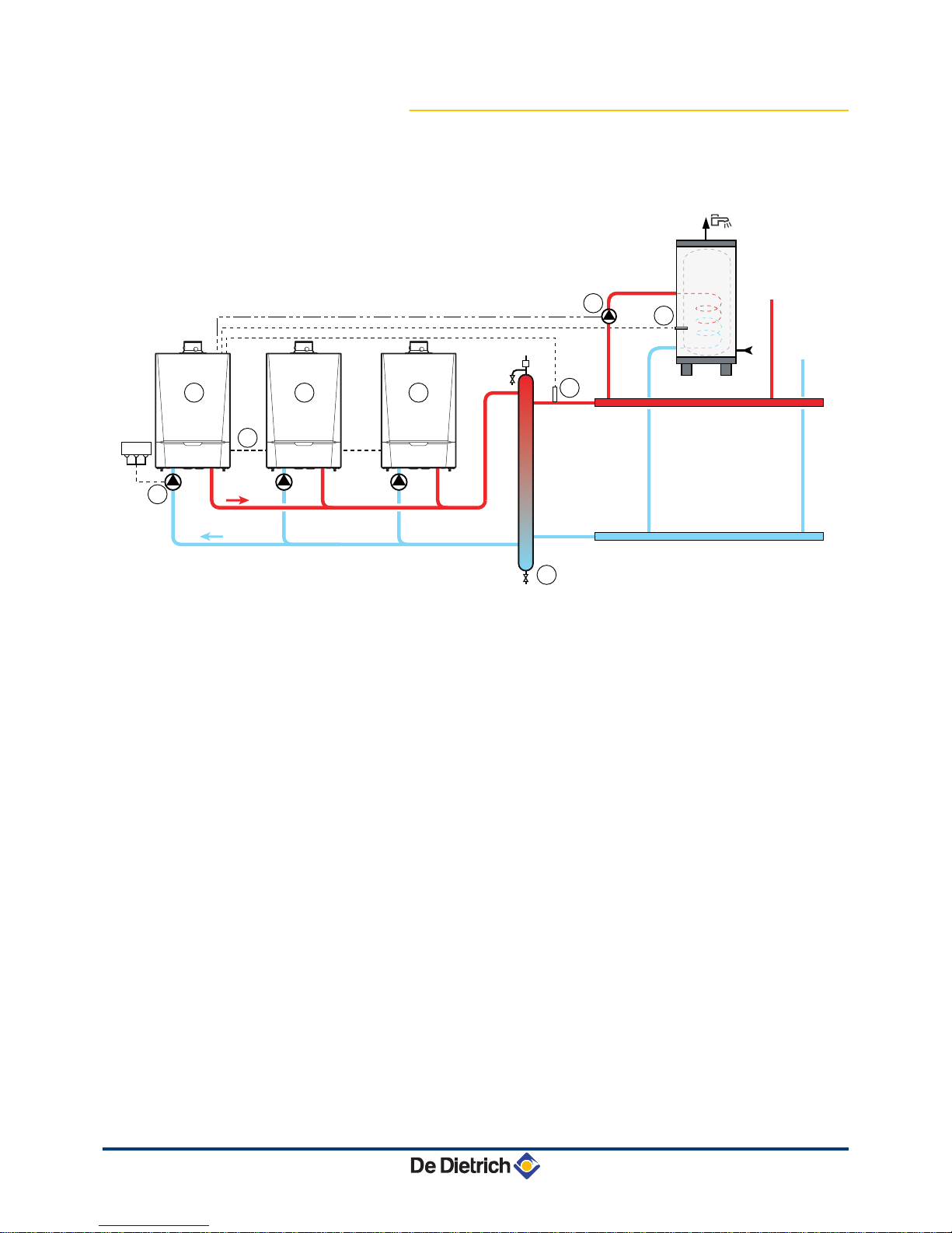
4.9.14. Connection in cascade
n
DHW tank after the mixing tank
A
Master boiler (DIEMATIC iSystem)
Z
Secondary boiler (DIEMATIC iSystem or IniControl)
E
Secondary boiler (DIEMATIC iSystem or IniControl)
R
Cable BUS
T
Boiler pump
Y
Low loss header
U
Cascade outlet sensor
Connect the sensor to the terminal block S SYST on the
master boiler.
I
D.H.W. load pump
O
Connect the DHW sensor (Package AD212)
C002910-B
5
1 2
6
7
8
9
4
3
X81
MCA 45 - 65 - 90 - 115 4. Installation
06/09/2010 - 300024755-001-A
49

DIEMATIC iSystem - Settings to be made for this type of installation: Master boiler
Parameters Access Settings to be made See
INSTALLATION
"Installer" level
#SYSTEM menu
EXTENDED
¼ "Displaying the parameters in extended
mode", page 65
O.DHW:
(1)
"Installer" level
#SYSTEM menu
PUMP
¼ "Setting the parameters specific to the
installation", page
66
CASCADE:
(1)
"Installer" level
#NETWORK menu
ON
¼ "Configuring the network", page
81
MASTER CONTROLLER
(1)
"Installer" level
#SYSTEM menu
ON
SYSTEM NETWORK
(1)
"Installer" level
#SYSTEM menu
ADD SLAVE
(1) The parameter is only displayed if INSTALLATION parameter is set to EXTENDED
DIEMATIC iSystem - Settings to be made for this type of installation: Follower boilers
Parameters Access Settings to be made See
INSTALLATION
"Installer" level
#SYSTEM menu
EXTENDED
¼ "Displaying the parameters in extended
mode", page 65
CASCADE:
(1)
"Installer" level
#NETWORK menu
ON
¼ "Configuring the network", page 81
MASTER CONTROLLER
(1)
"Installer" level
#SYSTEM menu
OFF
SLAVE NUMBER
(1)
"Installer" level
#SYSTEM menu
2, 3, ...
(1) The parameter is only displayed if INSTALLATION parameter is set to EXTENDED
IniControl - Settings to be made for this type of installation: Follower boilers
Parameters Access Settings to be made See
CASCADE: FBE
"Installer" level 1
¼ "Description of the parameters", page 100
SLAVE NUMBER FBF
"Installer" level 2, 3, ...
4. Installation MCA 45 - 65 - 90 - 115
50
06/09/2010 - 300024755-001-A
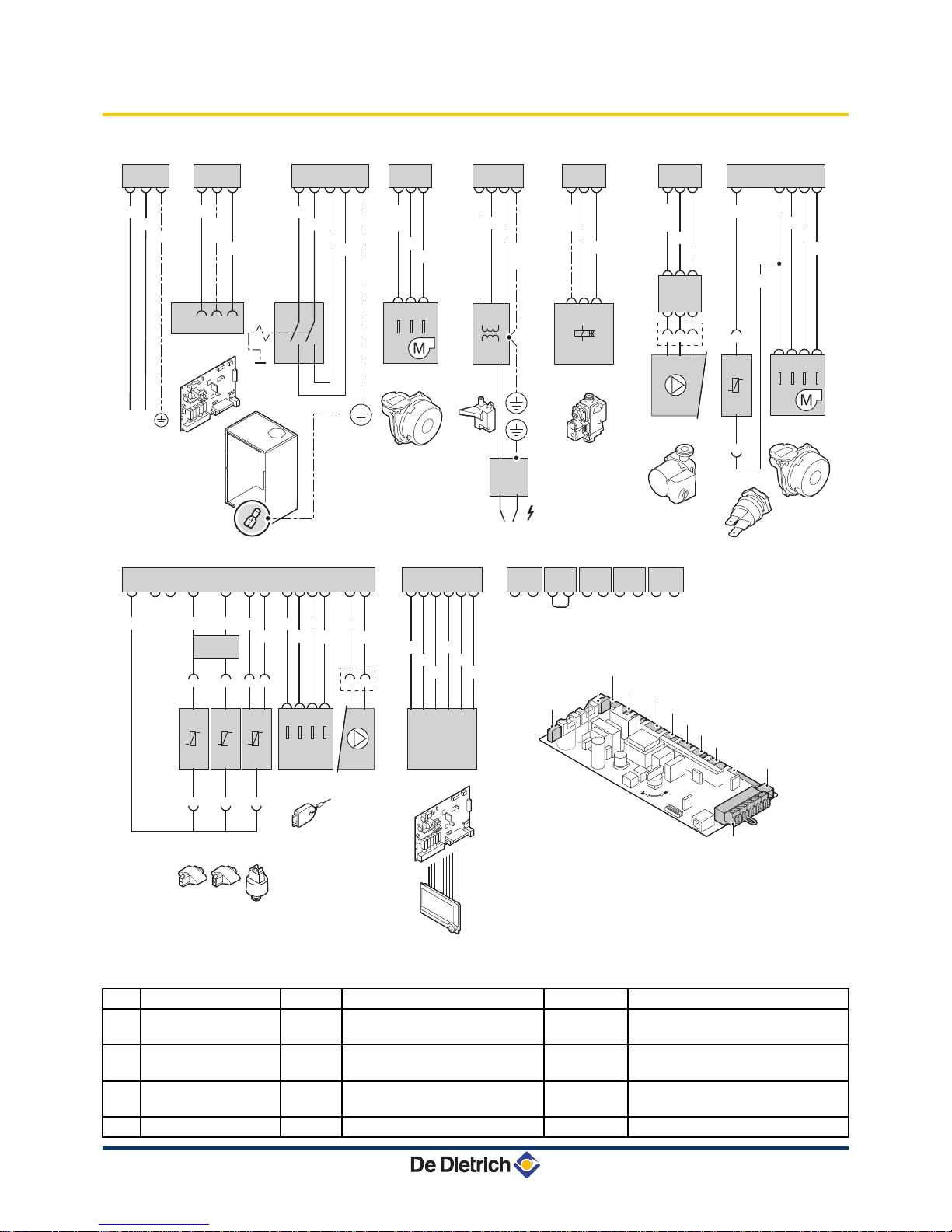
4.10 Electrical diagram
T002860-C
X1
X12
X3
X2
X4
X5
X6
X7
X8
X9
X10
X11
2 31
K1
SCU-C
X2
1 32
BL
BR
GN/
YW
SCU-C
X11
1 2 3 4 5 6
WH
GY
OR
RD
GN
YW
DIS
X12
1 2 7 8 9 103 4 5 6
P
230V, 50Hz
L N
X1
1 23
BR
BL
GN/YW
X3
4 3 2 15
BR
BL
BR
BL
GN/
YW
3 1
4 2
X51
S
X4
1 2 3
X41
BR
BL
GN/
YW
3 1 2
FAN
IT
X5
2 3 4 1
E
BK
BL
GN/
YW
GY
1 23
X51
X6
1 2 3
GN/
YW
WH
BL
GB
153
X21/X61
X8
1 2 3
PUMP A
BR
BL
GN/
YW
2 1 3
X81
3 1 2
X41
HLS
X9
2 3 4 5
X91
BK
BK
BK
BK
1 2 4 5
FAN
1
BK
BK
1
2
X117
PWM
PUMP
12 13
BK
BK
1 2
X116
FTSRTS
9
RD
1
BK
1
2 2
X115
8
BL
1
2
X114
PS
10 11
BK
BK
3 1
X112
2 3
X10
4 5 7 6
X111
BK
BK
BK
BK
1 2 3 4
PSU
P
Power supply
E
Ignition power relay
FTS
Flow sensor
SCU
Extended control PCB
GB
Combined venturi and gas valve
unit
PS
Pressure sensor
S
On/Off switch
PUMP A
Shunt pump
PSU
Parameter storage for PCBs PSU
and SU
FAN
Fan
HLS
Safety thermostat
PWM PUMP
Modulation signal from the boiler
pump
IT
Ignition transformer
RTS
Return sensor
DIS
Display
MCA 45 - 65 - 90 - 115 4. Installation
06/09/2010 - 300024755-001-A
51

4.11 Filling the system
4.11.1. Water treatment
In most cases, the boiler and the central heating installation can be
filled
with normal tap water and no water treatment will be necessary.
WARNING
Do not add chemical products to the central heating water
without consulting De Dietrich Thermique.
For example:
antifreeze, water softeners, products to increase or reduce
the pH value, chemical additives and/or inhibitors. These
may cause faults in the boiler and damage the heat
exchanger.
4 Rinse the central heating installation with at least 3x
the volume of the central heating installation.
Flush
the DHW pipes with at least 20 the volume of the
pipes.
4 Use only untreated tap water to fill or top up the level
in the central heating installation.
For an optimum functioning of the boiler, the water of the installation
must comply with following characteristics:
Total installed heat output (kW)
≤ 70
70 - 200 200 - 550 > 550
Degree of acidity (water
non-treated)
pH 7 - 9 7 - 9 7 - 9 7 - 9
Degree of acidity (water
treated)
pH 7 - 8,5 7 - 8,5 7 - 8,5 7 - 8,5
Conductivity at 25°C µS/cm ≤ 800 ≤ 800 ≤ 800 ≤ 800
Chlorides mg/l ≤ 150 ≤ 150 ≤ 150 ≤ 150
Other components mg/l < 1 < 1 < 1 < 1
Total water hardness
(1)
°f 1 - 35 1 - 20 1 - 15 1 - 5
°dH 0,5 - 20,0 0,5 - 11,2 0,5 - 8,4 0,5 - 2,8
mmol/l 0,1 - 3,5 0,1 - 2,0 0,1 - 1,5 0,1 - 0,5
(1) For
installations that are heated at constant high temperatures with a total installed heat output; up to 200 kW a maximum total water hardness
of 8,4 °dH (1,5 mmol/l, 15 °f) applies and for above 200 kW a maximum total water hardness of 2,8 °dH (0,5 mmol/l, 5 °f) applies
If a water treatment is necessary, De Dietrich
Thermique recommends the following manufacturers:
4 Cillit
4 Climalife
4 Fernox
4 Permo
4 Sentinel
4. Installation MCA 45 - 65 - 90 - 115
52
06/09/2010 - 300024755-001-A

4.11.2. Filling the siphon
1. Remove the siphon.
2.
Fill the siphon with water. This must be completely filled.
3. Re-assemble the siphon.
CAUTION
Fill the water siphon before starting the boiler to avoid
combustion products escaping from the boiler.
4.11.3. Filling the system
CAUTION
Before filling, open the valves on every radiator in the
installation.
In order to be able to read off the water pressure from the
boiler display, the boiler must be switched on.
1. Fill the system with clean tap water (advised water pressure is
between 1,5 and 2
bar).
2. Check the tightness of the water connections.
T002037-B
1
2
3
4
T000181-B
T001507-B
MCA 45 - 65 - 90 - 115 4. Installation
06/09/2010 - 300024755-001-A
53

5 Start-up - DIEMATIC iSystem
5.1 Control panel
5.1.1. Description of the keys
A
Temperature setting key (heating, DHW, swimming pool)
B
Operating mode selection key
C
DHW override key
D
Key to access the parameters reserved for the installer
E
Keys on which the function varies as and when selections
are made
F
Rotary setting button:
4 Turn
the rotary button to scroll through the menus or
modify a value
4 Press the rotary button to access the menu selected
or confirm a value modification
A000866-A
bar
STD
t
0 2 4 6 8 10 12 14 16 18 22 2420
p
b
AUTO
x
c
r
j
M
g
m
A
B
C
D
E
F
(
'
5. Start-up - DIEMATIC iSystem MCA 45 - 65 - 90 - 115
54
06/09/2010 - 300024755-001-A
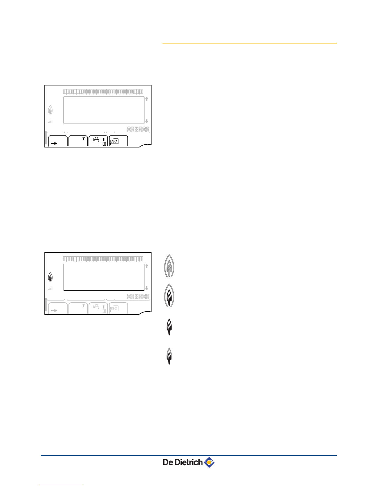
5.1.2. Description of the display
n
Key functions
>
Access to the various menus
(
Used to scroll through the menus
'
Used to scroll through the parameters
?
The symbol is displayed when help is available
f
Used to display the curve of the parameter selected
STD
Reset of the time programmes
b
Selection of comfort mode or selection of the days to be
programmed
v
Selection of reduced mode or deselection of the days to
be programmed
j
Back to the previous level
ESC
Back to the previous level without saving the
modifications made
t
Manual reset
n
Flame output level
C002705-A
The whole symbol flashes: The burner starts up but the
flame is not yet present
C002704-A
Part of the symbol flashes: Output is increasing
C002703-A
Steady symbol: The required output has been reached
C002702-A
Part of the symbol flashes: Output is dropping
bar
r
STD
(
'
t
0 2 4 6 8 10 12 14 16 18 22 2420
C002696-A
p
b
AUTO
x
c
r
j
L
g
m
bar
STD
t
0 2 4 6 8 10 12 14 16 18 22 2420
C002701-B
p
b
AUTO
x
c
r
j
M
g
m
MCA 45 - 65 - 90 - 115 5. Start-up - DIEMATIC iSystem
06/09/2010 - 300024755-001-A
55

n
Operating modes
p
Summer mode: The heating is off. Domestic hot water
continues to be produced
b
WINTER mode: Heating
and domestic hot water working
AUTO
Operation in automatic mode according to the timer
programme
x
Comfort mode: The symbol is displayed when a DAY
override (comfort) is activated
4 Flashing symbol: Temporary override
4 Steady symbol: Permanent override
m
Reduced mode: The symbol is displayed when a NIGHT
override (reduced) is activated
4 Flashing symbol: Temporary override
4 Steady symbol: Permanent override
g
Holiday mode: The symbol is displayed when a HOLIDAY
override (antifreeze) is activated
4 Flashing symbol: Holiday mode programmed
4 Steady symbol: Holiday mode active
m
Manual mode
n
System pressure
bar
Pressure indicator: The symbol is displayed when a water
pressure sensor is connected
4 Flashing
symbol: The quantity of water is insufficient
4 Steady symbol: The quantity of water is sufficient
l
Water pressure level
4 R : 0,9 to 1,1 bar
4 E : 1,2 to 1,5 bar
4 Z : 1,6 to 1,9 bar
4 A : 2,0 to 2,3 bar
4 l : > 2,4 bar
bar
STD
t
0 2 4 6 8 10 12 14 16 18 22 2420
C002697-B
p
b
AUTO
x
c
r
j
M
g
m
bar
STD
t
0 2 4 6 8 10 12 14 16 18 22 2420
C002698-B
p
b
AUTO
x
c
r
j
M
g
m
bar
STD
t
0 2 4 6 8 10 12 14 16 18 22 2420
C002708-A
p
b
AUTO
x
c
r
j
M
g
m
5. Start-up - DIEMATIC iSystem MCA 45 - 65 - 90 - 115
56
06/09/2010 - 300024755-001-A

n
Domestic Hot Water override
A bar is displayed when a DHW override is activated:
4 Flashing bar: Temporary override
4 Steady bar: Permanent override
n
Other information
r
The symbol is displayed when domestic hot water
production is running
w
Valve indicator: The symbol is displayed when a 3-way
valve is connected
4 x : 3-way valve open
4 c : 3-way valve closed
M
The symbol is displayed when the pump is operating
Name of the circuit for which the parameters are displayed
5.1.3. Access to the various browsing levels
n
"User" level
The information and settings in the "User" level can be accessed by
everyone.
1.
Press the > key.
bar
STD
t
0 2 4 6 8 10 12 14 16 18 22 2420
C002707-A
p
b
AUTO
x
c
r
j
M
g
m
bar
STD
t
0 2 4 6 8 10 12 14 16 18 22 2420
C002699-B
p
b
AUTO
x
c
r
j
M
g
m
bar
1
1
2
2
r
c
STD
(
'
t
v
0 2 4 6 8 10 12 14 16 18 22 2420
p
b
AUTO
x
c
r
j
M
g
m
SUNDAY 11:45
C002219-D-04
MCA 45 - 65 - 90 - 115 5. Start-up - DIEMATIC iSystem
06/09/2010 - 300024755-001-A
57

n
"Installer" level
The information and settings in the "Installer" level can be accessed
by experienced people.
1.
Press key - for around 5 seconds.
Before the "Installer" level is displayed, the EMISSION
MEASUREMENTS
menu will be displayed. Hold down the
-
key until #LANGUAGE is displayed.
n
"After Sales" level
The information and settings in the "After Sales" level can be
accessed by initiates.
1.
Press key - for around 10 seconds.
Before the "After Sales" level is displayed, the "Installer"
level will be displayed.
Hold key - down until
#PARAMETERS is displayed.
5.1.4. Browsing in the menus
1. To select the desired menu, turn the rotary button.
2.
To access the menu, press the rotary button.
To go back to the previous display, press the key j.
1
1
2
2
r
c
STD
(
'
t
v
0 2 4 6 8 10 12 14 16 18 22 2420
p
b
AUTO
x
c
r
j
M
g
m
SUNDAY 11:45
5
"
TEMP.: 68°
C002235-F-04
bar
1
1
2
2
r
c
STD
(
'
t
v
0 2 4 6 8 10 12 14 16 18 22 2420
p
b
AUTO
x
c
r
j
M
g
m
SUNDAY 11:45
10
"
TEMP.: _ _ _ _
C002272-C-04
bar
1
1
2
2
r
c
STD
(
'
t
v
0 2 4 6 8 10 12 14 16 18 22 2420
p
b
AUTO
x
c
r
j
L
g
m
#MEASURES
#CHOICE TIME PROG.
#TIME PROGRAM
#SETTING
#TIME .DAY
ÿ
C002220-A-04
5. Start-up - DIEMATIC iSystem MCA 45 - 65 - 90 - 115
58
06/09/2010 - 300024755-001-A

3. To select the desired parameter, turn the rotary button.
4.
To modify the parameter, press the rotary button.
To go back to the previous display, press the key j.
5. To modify the parameter, turn the rotary button.
6. To confirm, press the rotary button.
To cancel, press key h.
7. To go back to the main display, press key j2 times.
It is possible to use the (
and ' keys instead of the rotary
button.
5.2 Check points before commissioning
5.2.1. Preparing the boiler for commissioning
WARNING
Do not put the boiler into operation if the supplied gas is
not in accordance with the approved gas types.
Preparatory procedure for boiler commissioning:
4 Check
that the gas type supplied matches the data shown on the
boiler's data plate.
4 Check the gas circuit.
4 Check the hydraulic circuit.
4 Check the water pressure in the heating system.
4 Check the electrical connections to the thermostat and the other
external controls.
4 Check the other connections.
4 Test the boiler at full load. Check the setting of the gas/air ratio
and, if necessary, correct it.
bar
1
1
2
2
r
c
STD
(
'
t
v
0 2 4 6 8 10 12 14 16 18 22 2420
p
b
AUTO
x
c
r
j
L
g
m
CURRENT PROG.B
CURRENT PROG.C
P2
P3
ÿ
C002221-B-04
bar
1
1
2
2
r
c
STD
(
'
t
v
0 2 4 6 8 10 12 14 16 18 22 2420
p
b
AUTO
x
c
r
j
L
g
m
CURRENT PROG.C
"Choice of the timeprogram
applied C"
P4
ÿ
C002222-B-04
bar
1
1
2
2
r
c
STD
(
'
t
v
0 2 4 6 8 10 12 14 16 18 22 2420
p
b
AUTO
x
c
r
j
M
g
m
LUNDI 11:45
C002224-D-04
2x
MCA 45 - 65 - 90 - 115 5. Start-up - DIEMATIC iSystem
06/09/2010 - 300024755-001-A
59

4 Test the boiler at part load. Check the setting of the gas/air ratio
and, if necessary, correct it.
4 Finalizing work.
5.2.2.
Gas circuit
WARNING
Ensure that the boiler is switched off.
1. Open the main gas supply.
2. Unscrew
the two screws located under the front panel by a quarter
turn and remove the panel.
3. Tilt the control box forwards by opening the holding clips located
at the sides.
4. Check the gas supply pressure at the measurement point C on the
gas valve unit.
WARNING
¼
To ascertain the gas types permitted, see chapter:
"Equipment categories", page 8
5. Check the tightness of the gas connections made after the gas
valve unit in the boiler.
6.
Check the leak tightness of the gas inlet, including the gas
valves. The test pressure must not exceed 60 mbar.
7. Purge the gas supply pipe within the boiler by unscrewing the
measurement point on the gas block. Tighten the measurement
point when the pipe has been sufficiently purged.
8. Check the tightness of the gas connections in the boiler.
5.2.3. Hydraulic circuit
4 Check the syphon — this must be completely filled with clean
water.
4 Check that there are no leaks on the hydraulic connections.
5.2.4.
Electrical connections
4 Check the electrical connections.
5.3
Putting the appliance into operation
1. Tilt the control box upwards again and fasten it using the clips
located at the sides.
2.
Open the main gas supply.
3. Open the gas valve on the boiler.
T003243-A
C C
5. Start-up - DIEMATIC iSystem MCA 45 - 65 - 90 - 115
60
06/09/2010 - 300024755-001-A

4. Turn on the boiler using the on/off switch.
5. The
first time the boiler is powered up, the #LANGUAGE menu is
displayed. Select the desired language by turning the rotary
button.
6. To confirm, press the rotary button.
The boiler will begin an automatic venting-programme (which lasts
approx. 3 minutes) and will do this every time the power supply is
isolated.
Error during the start-up procedure:
4 No information is shown on the display:
- Check the mains supply voltage
- Check the fuses
- Check the connection of the power cable to the connector X1
on the PCU PCB
4 If there is a problem, the error is displayed on the screen.
¼ See chapter: "Messages (Code type Bxx or Mxx)", page
118
If a DHW sensor is connected and the anti-legionella
function is activated, the boiler starts to heat the water in
the DHW tank as soon as the vent programme has been
completed. The heating time depends on the size of the
DHW installation.
C002366-B
Français - Deutsch - English Italiano - Espanol - Nederlands
- Pycck - Polski - Türk -
bar
1
1
2
2
r
c
STD
(
'
t
v
0 2 4 6 8 10 12 14 16 18 22 2420
p
b
x
c
r
g
m
ÿ
LANGUE FRANCAIS
C002286-C
MCA 45 - 65 - 90 - 115 5. Start-up - DIEMATIC iSystem
06/09/2010 - 300024755-001-A
61

5.4 Gas settings
5.4.1. Adapting to another gas type
WARNING
Only a qualified engineer may carry out the following
operations.
The boiler is preset in the factory to operate on natural gas H (G20).
For operation on another group of gases, carry out the following
operations.
In case of functioning on propane:
1.
Boiler type For conversion to propane
MCA 45 Rotate the adjusting screw A on the venturi 4¾ turns in a
clockwise direction
MCA 65 Rotate the adjusting screw A on the venturi 6½ turns in a
clockwise direction
MCA 90 Fit the gas restrictor in the gas block
MCA 115 First turn the setting screw A
clockwise until it is closed, then:
Rotate the adjusting screw A on the gas block 3,5 - 4 turns in
an anticlockwise direction
2. Regulate the fan speed as indicated in the table (if required):
¼
See chapter: ""Professional" settings", page 75
3. Set
the air/gas ratio. For more detailed information on this subject,
see the following paragraphs:
¼
"Setting the air/gas ratio (Full load)", page 62
¼
"Setting the air/gas ratio (Part load)", page 64
5.4.2. Setting the air/gas ratio (Full load)
1. Unscrew the plug of the flue gas measurement point.
2.
Connect the flue gas analyser.
WARNING
Ensure that the opening around the sensor is completely
sealed when taking measurements.
T003241-A
A A
T001581-A
5. Start-up - DIEMATIC iSystem MCA 45 - 65 - 90 - 115
62
06/09/2010 - 300024755-001-A
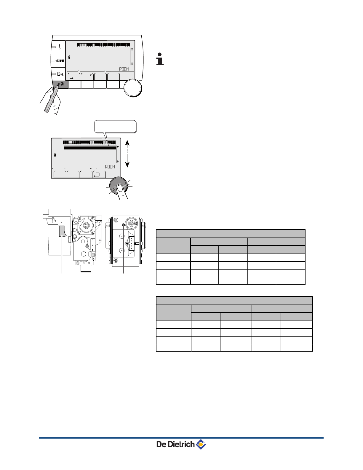
3. In the main display, press key -. The menu EMISSION
MEASUREMENTS is displayed on the screen.
If an automatic vent cycle is running, it is not possible to
perform these operations.
4. The characteristics of the generator are displayed.
5. Turn
the rotary button until PMAX is displayed. The full load is set.
6. Measure the percentage of O2 or CO2 in the flue gases.
7. Compare the values measured with the checking values given in
the table (Front panel removed):
8. If necessary, adjust the gas/air ratio using the adjusting screw
(A).
O2/CO2 control and setting values for gas
H (G20) at full load
Boiler type Setting value Checking value
O 2 (%) CO 2 (%) O 2 (%) CO 2 (%)
MCA 45 4,8 ± 0,2 9,0 ± 0,1 4,8 ± 0,5 9,0 ± 0,2
MCA 65 4,8 ± 0,2 9,0 ± 0,1 4,8 ± 0,5 9,0 ± 0,2
MCA 90 3,9 ± 0,2 9,5 ± 0,1 3,9 ± 0,5 9,5 ± 0,2
MCA 115 4,7 ± 0,2 9,1 ± 0,1 4,7 ± 0,5 9,1 ± 0,2
O2/ CO2 control and setting values for propane (
G31) at full load
Boiler type Setting value Checking value
O 2 (%) CO 2 (%) O 2 (%) CO 2 (%)
MCA 45 4,6 ± 0,2 10,7 ± 0,1 4,6 ± 0,5 10,7 ± 0,2
MCA 65 4,6 ± 0,2 10,7 ± 0,1 4,6 ± 0,5 10,7 ± 0,2
MCA 90 4,6 ± 0,2 10,7 ± 0,1 4,6 ± 0,5 10,7 ± 0,2
MCA 115 4,9 ± 0,2 10,5 ± 0,1 4,9 ± 0,5 10,5 ± 0,2
1
1
2
2
r
c
STD
(
'
t
v
0 2 4 6 8 10 12 14 16 18 22 2420
p
b
AUTO
x
c
r
j
M
g
m
SUNDAY 11:45
TEMP.: 68°
C002271-F-04
bar
1
1
2
2
r
c
STD
(
'
t
v
0 2 4 6 8 10 12 14 16 18 22 2420
p
b
AUTO
x
c
g
m
r
j
M
GENE :
BOILER TEMP.
CURRENT
FAILURE
PMAX
68°C
10µA
5600 tr/min
ÿ
C002347-D-04
OFF => PMAX
T003241-A
A A
MCA 45 - 65 - 90 - 115 5. Start-up - DIEMATIC iSystem
06/09/2010 - 300024755-001-A
63

5.4.3. Setting the air/gas ratio (Part load)
1. Unscrew the plug of the flue gas measurement point.
2.
Connect the flue gas analyser.
WARNING
Ensure that the opening around the sensor is completely
sealed when taking measurements.
3. In the main display, press key -. The menu EMISSION
MEASUREMENTS is displayed on the screen.
If an automatic vent cycle is running, it is not possible to
perform these operations.
4. The characteristics of the generator are displayed.
5. Turn
the rotary button until PMIN is displayed. The part load is set.
6. Measure the percentage of O2 or CO2 in the flue gases.
7. Compare the values measured with the checking values given in
the table (Front panel removed):
T001581-A
1
1
2
2
r
c
STD
(
'
t
v
0 2 4 6 8 10 12 14 16 18 22 2420
p
b
AUTO
x
c
r
j
M
g
m
SUNDAY 11:45
TEMP.: 68°
C002271-F-04
bar
1
1
2
2
r
c
STD
(
'
t
v
0 2 4 6 8 10 12 14 16 18 22 2420
p
b
AUTO
x
c
g
m
r
j
M
GENE :
BOILER TEMP.
CURRENT
FAILURE
PMIN
68°C
10µA
1850 tr/min
ÿ
C002348-D-04
OFF => PMIN
5. Start-up - DIEMATIC iSystem MCA 45 - 65 - 90 - 115
64
06/09/2010 - 300024755-001-A

8. If necessary, adjust the gas/air ratio using the adjusting screw
(B).
O2/CO2 control and setting values for gas H (G20) at low speed
Boiler type Setting value Checking value
O 2 (%) CO 2 (%) O 2 (%) CO 2 (%)
MCA 45 4,8 ± 0,2 9,0 ± 0,1 4,8 ± 0,5 9,0 ± 0,2
MCA 65 4,8 ± 0,2 9,0 ± 0,1 4,8 ± 0,5 9,0 ± 0,2
MCA 90 3,9 ± 0,2 9,5 ± 0,1 3,9 ± 0,5 9,5 ± 0,2
MCA 115 4,3 ± 0,2 9,3 ± 0,1 4,3 ± 0,5 9,3 ± 0,2
O2/CO2 control and setting values for propane (
G31) at low speed
Boiler type Setting value Checking value
O 2 (%) CO 2 (%) O 2 (%) CO 2 (%)
MCA 45 4,6 ± 0,2 10,7 ± 0,1 4,6 ± 0,5 10,7 ± 0,2
MCA 65 4,6 ± 0,2 10,7 ± 0,1 4,6 ± 0,5 10,7 ± 0,2
MCA 90 4,6 ± 0,2 10,7 ± 0,1 4,6 ± 0,5 10,7 ± 0,2
MCA 115 4,9 ± 0,2 10,5 ± 0,1 4,9 ± 0,5 10,5 ± 0,2
5.5 Checks and adjustments after commissioning
5.5.1. Displaying the parameters in extended
mode
The display mode on the control panel is set as standard in such a
way as only to show the "conventional" parameters.
It is possible to
switch to "extended" mode by proceeding as follows:
1. Access the "installer" level: Press key - for around 5 seconds.
2. Select the menu #SYSTEM.
4 Turn the rotary button to scroll through the menus or
modify a value.
4 Press the rotary button to access the menu selected
or confirm a value modification.
¼
For a detailed explanation of menu browsing, refer
to the chapter: "Browsing in the menus", page
58
3. Set the parameter INSTALLATION to EXTENDED.
"Installer" level - #SYSTEM menu
Parameter Adjustment range Description Factory setting Customer setting
INSTALLATION CLASSIC
Displays the parameters of a conventional
installation
CLASSIC
EXTENDED
Displays all parameters
Regardless of what is done to the keys, the regulator
switches back to CLASSIC mode after 30 minutes.
T003242-A
B B
B
1
1
2
2
r
c
STD
(
'
t
v
0 2 4 6 8 10 12 14 16 18 22 2420
p
b
AUTO
x
c
r
j
M
g
m
SUNDAY 11:45
5
"
TEMP.: 68°
C002235-F-04
MCA 45 - 65 - 90 - 115 5. Start-up - DIEMATIC iSystem
06/09/2010 - 300024755-001-A
65

5.5.2. Setting the parameters specific to the
installation
1. Access the "installer" level: Press key - for around 5 seconds.
2.
Select the menu #SYSTEM.
4 Turn the rotary button to scroll through the menus or
modify a value.
4 Press the rotary button to access the menu selected
or confirm a value modification.
¼
For a detailed explanation of menu browsing, refer
to the chapter: "Browsing in the menus", page
58
3. Set the following parameters according to the connections made
to the PCBs:
"Installer" level - #SYSTEM menu
Parameter Adjustment range Description Factory setting Customer
setting
CIRC. A:
(1)(2)
DIRECT
Use as a direct heating circuit
DIRECT
PROGRAM.
Use as an independent programmable outlet
H.TEMP
Enables operation of circuit A in summer despite
manual or automatic summer shutdown
DHW
Connection of a second domestic hot water tank
DHW ELEC
Used to control the electrical resistor according to the
timer programme on circuit A in summer mode
DISAB.
No data for circuit A is displayed
CIRC. B:
(1)
3WV
Connecting a circuit with 3-way valve (For example:
Underfloor heating
)
3WV
SWIM.P.
Using the circuit for pool management
DIRECT
Use of circuit in direct heating circuit
CIRC. C:
(1)
3WV
Connecting a circuit with 3-way valve (For example:
Underfloor heating
)
3WV
SWIM.P.
Using the circuit for pool management
DIRECT
Use of circuit in direct heating circuit
O.PUMP A
(1)
(2)
CH.PUMP A
Heating pump circuit A:
The PUMP A outlet is used to
control the pump on circuit A
CH.PUMP A
CIRC.AUX
Used to resume the functions of the S.AUX
parameter
without adding the "PCB + sensor" option (Package
AD249)
DHW LOOP
Used to control the domestic hot water looping pump
according to the DHW timer programme and force its
operation during an override
PRIMARY PUMP
The outlet PUMP A is active if a heating demand is
present on the secondary pump
ORDER BURNER
The outlet PUMP A is active when a burner demand
is present
FAILURE
The outlet PUMP A is active if an error is detected
O.DHW:
(1)
PUMP
Using a tank load pump on the DHW PUMP outlet
PUMP
RV
Use of a reversal valve for DHW production (Not
used)
(1) The parameter is only displayed if INSTALLATION parameter is set to EXTENDED
(2)
If the pump incorporated in the boiler is used for circuit A (parameter CIRC.A set to DIRECT), the O.PUMP A outlet is free
(3) This parameter is displayed only if the O.PUMP A parameter is set to CIRC.AUX or if the 3-way valve PCB option is used
1
1
2
2
r
c
STD
(
'
t
v
0 2 4 6 8 10 12 14 16 18 22 2420
p
b
AUTO
x
c
r
j
M
g
m
SUNDAY 11:45
5
"
TEMP.: 68°
C002235-F-04
5. Start-up - DIEMATIC iSystem MCA 45 - 65 - 90 - 115
66
06/09/2010 - 300024755-001-A

"Installer" level - #SYSTEM menu
Parameter Adjustment range Description Factory setting Customer
setting
BS60
(1)
ON
Small capacity tank
OFF
OFF
Large capacity tank
S.AUX:
(1)(3)
DHW LOOP
Use as a domestic loop pump
DHW LOOP
PROGRAM.
Use as an independent programmable outlet
PRIMARY PUMP
The outlet AUX PUMP is active if a heating demand
is present on the secondary pump
ORDER BURNER
The outlet AUX PUMP is active when a burner
demand is present
DHW
Use of primary circuit of second DHW tank
FAILURE
The outlet AUX PUMP
is active if an error is detected
DHW ELEC
Used to control the electrical resistor according to the
timer programme on circuit AUX
in summer mode
I.SYST
(1)
SYSTEM
The inlet sensor is used to connect the common flow
sensor of a cascade system
SYSTEM
STORAGE TANK
Hot water storage tank affected to heating only
DHW STRAT
Using the DHW tank with 2 sensors (top and bottom)
ST.TANK+DHW
Hot water storage tank affected to heating and
domestic hot water
O. TEL:
(1)
FAILURE
The telephone outlet is closed in the event of failure
FAILURE
REVISION
The telephone outlet is closed in the event of revision
display
DEF+REV
The telephone outlet is closed in the event of failure
or revision display
CT.TEL
(1)
CLOSE
See table below.
CLOSE
OPEN
I.TEL:
(1)
ANTIFR
Start anti-freeze in boiler command
ANTIFR
0/1 A
ON or OFF contact: I.TEL: can be used as an
antifreeze activation inlet on circuit
A
0/1 B
ON or OFF contact: I.TEL: can be used as an
antifreeze activation inlet on circuit
B
0/1 C
ON or OFF contact: I.TEL: can be used as an
antifreeze activation inlet on circuit
C
0/1 DHW
ON or OFF contact: I.TEL: can be used as an
antifreeze activation inlet on circuit
ECS
0/1 AUX
ON or OFF contact: I.TEL: can be used as an
antifreeze activation inlet on circuit AUX (S.AUX if
option *1 is present or outlet O.PUMP A is configured
as CIRC.AUX)
When I.TEL: is not active, the auxiliary circuit (AUX)
follows the maximum boiler temperature (parameter
BOILER MAX).
(1) The parameter is only displayed if INSTALLATION parameter is set to EXTENDED
(2)
If the pump incorporated in the boiler is used for circuit A (parameter CIRC.A set to DIRECT), the O.PUMP A outlet is free
(3) This parameter is displayed only if the O.PUMP A parameter is set to CIRC.AUX or if the 3-way valve PCB option is used
MCA 45 - 65 - 90 - 115 5. Start-up - DIEMATIC iSystem
06/09/2010 - 300024755-001-A
67

Influence of the parameter setting CT.TEL on the I.TEL contact
CT.TEL I.TEL: I.TEL contact closed I.TEL contact open
CLOSE ANTIFR
The antifreeze mode is active on all boiler circuits. The mode selected on the boiler is active.
0/1 A
The mode selected on the circuit is active. The antifreeze mode is active on the circuit
concerned.
0/1 B
The mode selected on the circuit is active. The antifreeze mode is active on the circuit
concerned.
0/1 C
The mode selected on the circuit is active. The antifreeze mode is active on the circuit
concerned.
0/1 DHW
The mode selected on the DHW circuit is active. The antifreeze mode is active for the DHW circuit.
0/1 AUX
4 The MAUX outlet on the connection terminal
block is active.
4 The boiler operates at a set point temperature
equal to BOILER MAX.
4 The MAUX outlet on the connection terminal
block is not active.
4 The
boiler operates with a set point temperature
as a function of the outside temperature.
OPEN ANTIFR
The mode selected on the boiler is active. The antifreeze mode is active on all boiler circuits.
0/1 A
The antifreeze mode is active on the circuit
concerned.
The mode selected on the circuit is active.
0/1 B
The antifreeze mode is active on the circuit
concerned.
The mode selected on the circuit is active.
0/1 C
The antifreeze mode is active on the circuit
concerned.
The mode selected on the circuit is active.
0/1 DHW
The antifreeze mode is active for the DHW circuit. The mode selected on the DHW circuit is active.
0/1 AUX
4 The MAUX outlet on the connection terminal
block is not active.
4 The boiler operates with a set point temperature
as a function of the outside temperature.
4 The MAUX outlet on the connection terminal
block is active.
4 The boiler operates at a set point temperature
equal to BOILER MAX.
5.5.3. Naming the circuits and generators
1. Access the "installer" level: Press key - for around 5 seconds.
2.
Select the menu #NAMES OF THE CIRCUITS.
4 Turn the rotary button to scroll through the menus or
modify a value.
4 Press the rotary button to access the menu selected
or confirm a value modification.
¼
For a detailed explanation of menu browsing, refer
to the chapter: "Browsing in the menus", page
58
1
1
2
2
r
c
STD
(
'
t
v
0 2 4 6 8 10 12 14 16 18 22 2420
p
b
AUTO
x
c
r
j
M
g
m
SUNDAY 11:45
5
"
TEMP.: 68°
C002235-F-04
5. Start-up - DIEMATIC iSystem MCA 45 - 65 - 90 - 115
68
06/09/2010 - 300024755-001-A

3. Select the circuit or generator you wish to rename.
"Installer" level - #NAMES OF THE CIRCUITS menu
Parameter Description Name given by the customer
CIRC. A:
Circuit A
CIRC. B:
Circuit B
CIRC. C:
Circuit C
CIRC.AUX
Auxiliary circuit
CIRC.DHW
Domestic hot water circuit
GENE
Generator
4. Turn the rotary button to choose the first character from the list.
To confirm, press the rotary button.
5.
Then press again to enter a second character or turn the rotary
button to leave an empty space.
6. Choose the other characters in the same way. The input zone may
contain up to 6 characters.
To move from one character to another, turn the rotary
button. To exit without modifications, press key h.
7. To confirm the name, press the rotary button and then turn the
button slightly anti-clockwise. When the symbol U appears, press
the rotary button. The name is confirmed.
If the name reaches 6 characters, it is automatically
confirmed when the last character is confirmed.
5.5.4. Setting the heating curve
If an outside temperature sensor is connected, it is possible to adapt
the heating curve.
1.
Access the "installer" level: Press key - for around 5 seconds.
2. Select the menu #SECONDARY INSTAL.P.
4 Turn the rotary button to scroll through the menus or
modify a value.
4 Press the rotary button to access the menu selected
or confirm a value modification.
¼
For a detailed explanation of menu browsing, refer
to the chapter: "Browsing in the menus", page
58
bar
1
1
2
2
r
c
STD
(
'
t
v
0 2 4 6 8 10 12 14 16 18 22 2420
p
b
AUTO
x
c
r
j
L
g
m
CIRC.B I
"Personalize the nameof this circuit B"
ÿ
E
F
G
H
.
.
.
C002344-C-04
I
bar
1
1
2
2
r
c
STD
(
'
t
v
0 2 4 6 8 10 12 14 16 18 22 2420
p
b
AUTO
x
c
r
j
L
g
m
CIRC.B INPUT
"Personalize the nameof this circuit B"
ÿ
X
Y
Z
.
.
.
C002345-C-04
1
1
2
2
r
c
STD
(
'
t
v
0 2 4 6 8 10 12 14 16 18 22 2420
p
b
AUTO
x
c
r
j
M
g
m
SUNDAY 11:45
5
"
TEMP.: 68°
C002235-F-04
MCA 45 - 65 - 90 - 115 5. Start-up - DIEMATIC iSystem
06/09/2010 - 300024755-001-A
69

3. Select the parameter HEAT.CURV. ....
4.
To modify the value directly, turn the rotary button.
To modify the value by displaying the curve, press key f.
5. To modify the curve, turn the rotary button.
6. To confirm, press the rotary button.
To cancel, press key h.
0.7 = Heating curve set
n
Heating curve without BCT
The BCT (Base heat Curve Temperature) allows a minimum
operating temperature to be imposed on the heating circuit (this
temperature may be constant if the circuit gradient is nil).
A
Maximum temperature of the circuit
Z
Water temperature in the circuit for an outside
temperature of 0°C
E
DAY set point on the circuit
R
Outside temperature for which the maximum water
temperature in the circuit is reached
T
Value of the heating curve
This value corresponds to the parameter HEAT.CURV.
¼ See chapter: ""Professional" settings", page 75
.
When you modify the heating curve, Z and T are
recalculated and repositioned automatically.
bar
1
1
2
2
r
c
STD
(
'
t
v
0 2 4 6 8 10 12 14 16 18 22 2420
p
b
AUTO
x
c
r
j
M
g
m
BUILD.INERTIA
CIRC.CURVE B
CIRC.CURVE C
SCREED DRYING
3
2.0
0.7
No
ÿ
C002316-D-04
bar
1
1
2
2
r
c
STD
(
'
t
v
0 2 4 6 8 10 12 14 16 18 22 2420
p
b
AUTO
x
c
r
j
M
g
m
CIRC.CURVE B
"Slope of the heatcurve of the
circuit B"
2.0
C002317-D-04
bar
1
1
2
2
r
c
STD
(
'
t
v
0 2 4 6 8 10 12 14 16 18 22 2420
p
b
AUTO
x
c
r
j
M
g
m
75
64
50
020 -15
C002318-B-04
0,7
0.7
20 0 -16
50
75
C°
C°
1.5
C002319-B
1
2
3
4
5
5. Start-up - DIEMATIC iSystem MCA 45 - 65 - 90 - 115
70
06/09/2010 - 300024755-001-A
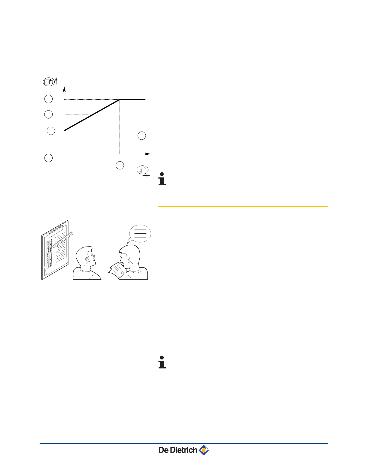
n
Heating curve with BCT
The BCT (Base heat Curve Temperature) allows a minimum
operating temperature to be imposed on the heating circuit (this
temperature may be constant if the circuit gradient is nil).
A
Maximum temperature of the circuit
Z
Water temperature in the circuit for an outside
temperature of 0°C
E
DAY set point on the circuit
R
Outside temperature for which the maximum water
temperature in the circuit is reached
T
Value of the heating curve
This value corresponds to the parameter HEAT.CURV.
¼ See chapter: ""Professional" settings", page 75
.
x
Value set to the parameter HCZP D
When you modify the heating curve, Z and T are
recalculated and repositioned automatically.
5.5.5. Finalizing work
1. Remove the measuring equipment.
2.
Put the flue gas sampling plug back in place.
3. Refit the front panel. Tighten the two screws by a quarter turn.
4. Raise the temperature in the heating system to approximately
70°C.
5. Shut down the boiler.
6. After about 10 minutes, vent the air in the heating system.
7. Checking the hydraulic pressure. If necessary, top up the water
level in the heating system (recommended hydraulic pressure
between 1,5 and 2 bar).
8. Tick the gas category used on the data plate.
9. Explain the operation of the installation, the boiler and the
regulator to the users.
10.Inform the user of the periodicity of maintenance work to be carried
out. Input the service date and the contact details of the installer.
11.Give all the instruction manuals to the user.
Commissioning of the boiler is now complete.
The various boiler parameters are preset in the factory.
These factory settings are suitable for the most common
heating systems. For other systems and situations, the
parameters can be modified.
20 0 -15
64
50
75
C°
C°
0.7
C002320-B
1
2
X
3
4
5
T001522-A
MCA 45 - 65 - 90 - 115 5. Start-up - DIEMATIC iSystem
06/09/2010 - 300024755-001-A
71

5.6 Reading out measured values
The various values measured by the appliance are displayed in the
#MEASURES menu.
1.
To access "user" level: Press the > key.
2. To select the #MEASURES menu.
4 Turn the rotary button to scroll through the menus or
modify a value.
4 Press the rotary button to access the menu selected
or confirm a value modification.
¼
For a detailed explanation of menu browsing, refer
to the chapter: "Browsing in the menus", page
58.
"User" level - #MEASURES menu
Parameter Description Unit
OUTSIDE TEMP.
Outside temperature °C
ROOMTEMP. A
(1)
Room temperature of circuit A °C
ROOMTEMP. B
(1)
Room temperature of circuit B °C
ROOMTEMP. C
(1)
Room temperature of circuit C °C
BOILER TEMP.
Water temperature in the boiler °C
PRESSURE
Water pressure in the installation bar
WATER TEMP.
(1)
Water temperature in the DHW tank °C
INST DWH TEMP.
(1)
Instant hot water temperature °C
STOR.TANK.TEMP
(1)
Water temperature in the storage tank °C
DCW TEMPERATURE
Domestic cold water temperature °C
SWIMMING P.T.B
(1)
Water temperature of the swimming pool on circuit B °C
SWIMMING P.T.C
(1)
Water temperature of the swimming pool on circuit C °C
OUTLET TEMP. B
(1)
Temperature of the flow water in circuit B °C
OUTLET TEMP. C
(1)
Temperature of the flow water in circuit C °C
SYSTEM TEMP.
(1)
Temperature of the system flow water if multi-generator °C
T.DHW BOTTOM
Water temperature in the bottom of the DHW tank °C
TEMP.TANK AUX
(1)
Water temperature in the second DHW tank connected to the AUX circuit °C
DHW A TEMP.
(1)
Water temperature in the second DHW tank connected to circuit A °C
BACK TEMP
Temperature of the boiler return water °C
WIND SPEED
Fan rotation speed rpm
POWER
Instantaneous boiler output (0%: Burner off or running at minimum output) %
CURRENT (µA) Ionization current µA
NB IMPULS.
Number of burner start-ups (not restartable)
The meter is incremented by 8 every 8 start-ups
RUNTIME
Number of burner operation hours (not restartable)
The meter is incremented by 2 every 2 hours
h
IN 0-10V
(1)
Voltage at input 0-10 V V
SEQUENCE
Control system sequence
CTRL
Software control number
(1) The parameter is only displayed for the options, circuits or sensors actually connected.
bar
1
1
2
2
r
c
STD
(
'
t
v
0 2 4 6 8 10 12 14 16 18 22 2420
p
b
AUTO
x
c
r
j
M
g
m
SUNDAY 11:45
C002219-D-04
5. Start-up - DIEMATIC iSystem MCA 45 - 65 - 90 - 115
72
06/09/2010 - 300024755-001-A

5.7 Changing the settings
The boiler control panel is set for the most common heating
systems. With
these settings, practically all heating systems operate
correctly. The user or installer can optimise the parameters according
to own preferences.
¼ For the "user" settings, refer to the user instructions.
5.7.1. Language selection
1. Access the "installer" level: Press key - for around 5 seconds.
2.
Select the menu #LANGUAGE.
4 Turn the rotary button to scroll through the menus or
modify a value.
4 Press the rotary button to access the menu selected
or confirm a value modification.
¼
For a detailed explanation of menu browsing, refer
to the chapter: "Browsing in the menus", page
58
"Installer" level - #LANGUAGE menu
Adjustment range Description
FRANCAIS Display in French
DEUTSCH Display in German
ENGLISH Display in English
ITALIANO Display in Italian
ESPANOL Display in Spanish
NEDERLANDS Display in Dutch
POLSKY Display in Polish
5.7.2. Calibrating the sensors
1. To access "user" level: Press the > key.
2.
To select the #SETTING menu.
4 Turn the rotary button to scroll through the menus or
modify a value.
4 Press the rotary button to access the menu selected
or confirm a value modification.
¼
For a detailed explanation of menu browsing, refer
to the chapter: "Browsing in the menus", page
58
3. To set the following parameters:
1
1
2
2
r
c
STD
(
'
t
v
0 2 4 6 8 10 12 14 16 18 22 2420
p
b
AUTO
x
c
r
j
M
g
m
SUNDAY 11:45
5
"
TEMP.: 68°
C002235-F-04
bar
1
1
2
2
r
c
STD
(
'
t
v
0 2 4 6 8 10 12 14 16 18 22 2420
p
b
AUTO
x
c
r
j
M
g
m
SUNDAY 11:45
C002219-D-04
MCA 45 - 65 - 90 - 115 5. Start-up - DIEMATIC iSystem
06/09/2010 - 300024755-001-A
73

"User" level - #SETTING menu
Parameter Adjustment range Description Factory setting Customer
setting
SUM/WIN 15 to 30 °C Used to set the outside temperature above
which heating will be shut down.
4 The heating pumps are shut down.
4 The burner will only start for domestic
hot water needs.
4 The letter E and the symbol p are
displayed.
22 °C
NO
Heating is never shut down automatically
CALIBR. OUT
Outside sensor calibration: Used to correct
the outside temperature
Outside
temperature
CALIBR. ROOM A
(1)(1)
Calibration of the room sensor on circuit A:
Is used to set a room offset
Make
this setting 2 hours after switching on,
when the room temperature has stabilised
Room temperature
of circuit A
OFFSET ROOM A
(1)
-5.0 to +5.0 °C Room offset on circuit A: Is used to set a
room offset
Make
this setting 2 hours after switching on,
when the room temperature has stabilised
0.0
ANTIFR. ROOM A 0.5 to 20 °C Room temperature antifreeze activation on
circuit A
6 °C
CALIBR. ROOM B
(1)(1)
Calibration of the room sensor on circuit B:
Is used to set a room offset
Make
this setting 2 hours after switching on,
when the room temperature has stabilised
Room temperature
of circuit B
OFFSET ROOM B
(1)
-5.0 to +5.0 °C Room offset on circuit B: Is used to set a
room offset
Make
this setting 2 hours after switching on,
when the room temperature has stabilised
0.0
ANTIFR. ROOM B 0.5 to 20 °C Room temperature at which the antifreeze
mode is activated on circuit B
6 °C
CALIBR. ROOM C
(2)(1)
Calibration of the room sensor on
circuit C: Is used to set a room offset
Make
this setting 2 hours after switching on,
when the room temperature has stabilised
Room temperature
of circuit C
OFFSET ROOM C
(3)(1)
-5.0 to +5.0 °C Room offset on circuit C: Is used to set a
room offset
Make
this setting 2 hours after switching on,
when the room temperature has stabilised
0.0
ANTIFR. ROOM C
(4)
0.5 to 20 °C Room temperature antifreeze activation on
circuit C
6 °C
(1) The parameter is only displayed if INSTALLATION parameter is set to EXTENDED
(2)
The parameter is only displayed if a room sensor is connected to the circuit concerned
(3) The parameter is only displayed if no room sensor is connected to the circuit concerned or the sensor has no influence
(4) The parameter is only displayed if the circuit concerned is actually connected
5. Start-up - DIEMATIC iSystem MCA 45 - 65 - 90 - 115
74
06/09/2010 - 300024755-001-A

5.7.3. "Professional" settings
1. Access the "installer" level: Press key - for around 5 seconds.
2.
To set the following parameters:
4 Turn the rotary button to scroll through the menus or
modify a value.
4 Press the rotary button to access the menu selected
or confirm a value modification.
¼
For a detailed explanation of menu browsing, refer
to the chapter: "Browsing in the menus", page
58
"Installer" level - #PRIMARY LIMITS menu
Parameter Adjustment range Description Factory setting Customer setting
BOILER MAX
20 to 90 °C Maximum boiler temperature 80 °C
MAX.R.HEAT(%)
(1)
0-100% Maximum boiler output during heating 100%
MAX.DHW(%)
(1)(2)
0-100% Maximum boiler output in DHW 100%
MIN.VENT.
(1)
1000-5000 rpm Minimum fan speed See table below
MAX.VENT.BOIL
(1)
1000-7000 rpm Maximum fan speed setting in heating See table below
MAX.VENT.DHW
(1)
1000-7000 rpm Maximum fan speed setting in domestic
hot water
See table below
START RPM
(1)
1000-5000 rpm Optimum start-up speed setting See table below
MIN.PUMP SPEED
(1)
20-100% Minimum pump speed 40 %
MAX.PUMP SPEED
(1)
20-100% Maximum pump speed 100 %
(1) The parameter is only displayed if INSTALLATION parameter is set to EXTENDED
(2)
The parameter is only displayed if P.DHW is set to PUMP
"Installer" level - #SECONDARY LIMITS menu
Parameter Adjustment range Description Factory setting
MAX.CIRC.A
20 to 95 °C Maximum temperature (Circuit A)
See comments below
75 °C
MAX.CIRC.B
20 to 95 °C Maximum temperature (Circuit B)
See comments below
50 °C
MAX.CIRC.C
20 to 95 °C Maximum temperature (Circuit C)
See comments below
50 °C
OUT.ANTIFREEZE
OFF, -8 to +10 °C Outside temperature at which the installation's antifreeze protection
is activated.
Below this temperature the pumps are permanently on and the
minimum temperatures for each circuit are respected.
When NIGHT
: STOP is set, the reduced temperature is maintained
in each circuit (#SECONDARY INSTAL.P menu).
OFF: Antifreeze protection is not activated
+3 °C
HCZP D A
(1)(2)
OFF, 20 to 90 °C Curve base temperature in Daytime mode (Circuit A)
OFF
HCZP N A
(1)(2)
OFF, 20 to 90 °C Curve base temperature in Nighttime mode (Circuit A)
OFF
HCZP D B
(1)(2)
OFF, 20 to 90 °C Curve base temperature in Daytime mode (Circuit B)
OFF
HCZP N B
(1)(2)
OFF, 20 to 90 °C Curve base temperature in Nighttime mode (Circuit B)
OFF
(1) The parameter is only displayed if INSTALLATION parameter is set to EXTENDED
(2)
The parameter can be set to the heating curve by pressing key f.
1
1
2
2
r
c
STD
(
'
t
v
0 2 4 6 8 10 12 14 16 18 22 2420
p
b
AUTO
x
c
r
j
M
g
m
SUNDAY 11:45
5
"
TEMP.: 68°
C002235-F-04
MCA 45 - 65 - 90 - 115 5. Start-up - DIEMATIC iSystem
06/09/2010 - 300024755-001-A
75

"Installer" level - #SECONDARY LIMITS menu
Parameter Adjustment range Description Factory setting
HCZP D C
(1)(2)
OFF, 20 to 90 °C Curve base temperature in Daytime mode (Circuit C)
OFF
HCZP N C
(1)(2)
OFF, 20 to 90 °C Curve base temperature in Nighttime mode (Circuit C)
OFF
PRIM.TEMP.DHW
50 to 90 °C Boiler temperature setting if producing domestic hot water 80 °C
(1) The parameter is only displayed if INSTALLATION parameter is set to EXTENDED
(2)
The parameter can be set to the heating curve by pressing key f.
"Installer" level - #PRIMARY INSTAL.P menu
(1)
Parameter Adjustment range Description Factory setting Customer
setting
BURN.MIN.RUN
0 to 180 seconds Setting the burner minimum operation time (In
heating mode
)
30 seconds
TIMER GENE P.
1 to 30 minutes Maximum post-operation duration of the
generator pump
4 minutes
IN.BL STOP HEAT
Configuration of the PCU BL inlet
If the contact is open, the heating is off. If the
parameter P.DHW is set to VI, DHW production
nevertheless remains functional.
Automatic
restart when the contact closes.
TOTAL STOP
TOTAL STOP
Configuration of the PCU BL inlet
If the contact is open, heating and DHW
production are off. Automatic restart when the
contact closes.
SAFETY MODE
Configuration of the PCU BL inlet
If the contact is open, the boiler goes into safety
lockout. The boiler needs to be reset to restart.
(1) The menu is displayed only if the INSTALLATION parameter is set to EXTENDED
"Installer" level - #SECONDARY INSTAL.P menu
Parameter Adjustment range Description Factory
setting
Customer
setting
BUILD. INERTIA
(1)
0 (10 hours) to 10
(50 hours)
Characterisation of building's inertia:
0 for a building with low thermal inertia.
3 for a building with normal thermal
inertia.
10
for a building with high thermal inertia.
Modification of the factory setting is
only useful in exceptional cases.
3 (22 hours)
CIRC.CURVE A
(2)
0 to 4 Heating curve of the circuit A
See comments below
1.5
ROOM INFL. A
(1)
0 to 10 Influence of room sensor A
See comments below
3
CIRC.CURVE B
(2)
0 to 4 Heating curve of the circuit B
See comments below
0.7
ROOM INFL. B
(1)
0 to 10 Influence of room sensor B
See comments below
3
CIRC.CURVE C
(2)
0 to 4 Heating curve of the circuit C
See comments below
0.7
(1) The parameter is only displayed if INSTALLATION parameter is set to EXTENDED
(2) The parameter can be set to the heating curve by pressing key f
(3) The parameter is only displayed if SCREED DRYING is other than OFF
(4) The parameter is only displayed if IN 0-10V is set to ON.
(5) If a reversal valve is connected, DHW priority will always be total regardless of the setting.
5. Start-up - DIEMATIC iSystem MCA 45 - 65 - 90 - 115
76
06/09/2010 - 300024755-001-A

"Installer" level - #SECONDARY INSTAL.P menu
Parameter Adjustment range Description Factory
setting
Customer
setting
ROOM INFL. C
(1)
0 to 10 Influence of room sensor C
See comments below
3
SCREED DRYING NO, B, C, B+C
Drying the floor
See comments below
NO
START DRYING
TEMP
(3)
20 to 50 °C Screed drying start temperature 20 °C
STOP DRYING
TEMP
(3)
20 to 50 °C Screed drying stop temperature 20 °C
NUMB. DAYS DRY.
(3)
0 to 99
0
NIGHT
(1)
DEC.
The lower temperature is maintained
(Night mode)
See comments below
DEC.
STOP
The boiler is stopped (Night mode)
See comments below
IN 0-10V
OFF / TEMPERATURE /
POWER %
Activating the control at 0-10 V
See comments below
OFF
VMIN/OFF 0-10V
(1)(4)
0 to 10 V Voltage corresponding to the instruction
set minimum
0.5 V
VMAX 0-10V
(1)(4)
0 to 10 V Voltage corresponding to the instruction
set maximum
9.5 V
CONS.MIN 0-10V
(1)
(4)
10 to 70 °C Instruction minimum set temperature 20 °C
CONS.MAX 0-10V
(1)
(4)
10 to 100 °C Maximum set temperature 80 °C
BAND WIDTH
(1)
4 to 16 K Control unit bandwidth for the 3-way
valves.
Option of increasing the bandwidth if the
valves
are rapid or of reducing it if they are
slow.
12 K
BOIL/3WV SHIFT
(1)
0 to 16 K Minimum temperature difference
between the boiler and the valves
4 K
H. PUMP DELAY
(1)
0 to 15 minutes Timing of the shutdown of the heating
pumps.
The timing of heating pump shutdown
prevents the boiler overheating.
4 minutes
HW. PUMP DELAY
(1)
(2)
2 to 15 minutes Timing of the shutdown of the domestic
hot water pump.
The
timing of the domestic hot water load
pump shutdown prevents the boiler and
the heating circuits overheating (Only if a
load pump is used).
2 minutes
ADAPT ON
Automatic adaptation of the heating
curves
for each circuit with a room sensor
with an influence of >0.
ON
OFF
The heating curves can only be modified
manually.
(1) The parameter is only displayed if INSTALLATION parameter is set to EXTENDED
(2)
The parameter can be set to the heating curve by pressing key f
(3) The parameter is only displayed if SCREED DRYING is other than OFF
(4) The parameter is only displayed if IN 0-10V is set to ON.
(5) If a reversal valve is connected, DHW priority will always be total regardless of the setting.
MCA 45 - 65 - 90 - 115 5. Start-up - DIEMATIC iSystem
06/09/2010 - 300024755-001-A
77

"Installer" level - #SECONDARY INSTAL.P menu
Parameter Adjustment range Description Factory
setting
Customer
setting
PRIORITY DHW
(5)
TOTAL
Interruption of pool heating and reheating
during domestic hot water production.
TOTAL
SLIDING
Domestic hot water production and
heating on the valve circuits if the
available output is sufficient and the
hydraulic connection allows.
NO
Heating and domestic hot water
production in parallel if the hydraulic
connection allows.
a
Risk of overheating in the direct circuit.
LEG PROTEC
The "anti legionella" function acts to
prevent the development of legionella in
the dhw tank, these bacteria are
responsible for legionellosis.
OFF
OFF
Anti-legionella function not activated
DAILY
The tank is overheated every day from
4:00 o'clock to 5:00 o'clock
WEEKLY
The tank is overheated every Saturday
from 4:00 o'clock to 5:00 o'clock
(1) The parameter is only displayed if INSTALLATION parameter is set to EXTENDED
(2)
The parameter can be set to the heating curve by pressing key f
(3) The parameter is only displayed if SCREED DRYING is other than OFF
(4) The parameter is only displayed if IN 0-10V is set to ON.
(5) If a reversal valve is connected, DHW priority will always be total regardless of the setting.
n
MAX.CIRC...
WARNING
If using underfloor heating, do not modify the factory
setting (50 °C). To install this, please consult existing
legislation.
4 In the case of a direct circuit, connect a safety thermostat to the
BL contact.
4 In the case of a 3-way valve circuit (B or C), connect a safety
thermostat to the TS contact.
n
CIRC. CURVE ...
Heating curve circuit A, B or C
x
Outside temperature (°C)
y
Water flow temperature (°C)
A
Maximum temperature of the circuit B - C
M001678-B
1
5. Start-up - DIEMATIC iSystem MCA 45 - 65 - 90 - 115
78
06/09/2010 - 300024755-001-A

n
SCREED DRYING
Used to force a constant flow temperature or a train to accelerate
screed drying on underfloor heating.
The setting for these temperatures must follow the screed-layer's
recommendations.
Activation of this parameter (setting other than OFF) forces the
permanent display of SCREED DRYING and deactivates all other
control system functions.
When floor drying is active on a circuit, all other circuits (e.g. DHW)
are shut down. The use of this function is only possible on circuits
B
and C.
A
STOP DRYING TEMP
Z
START DRYING TEMP
E
Today
R
NUMB. DAYS DRY.
T
Normal regulation (End of drying)
Y
Heating temperature setting (°C)
For example
A
STOP DRYING TEMP: 47 °C
Z
START DRYING TEMP: 20 °C
R
NUMB. DAYS DRY.
T
Normal regulation (End of drying)
Y
Heating temperature setting (°C)
Every day at midnight (00:00): the set point (START
DRYING
TEMP) is recalculated and the remaining number
of days (NB DAYS DRYING) is decremented.
n
ROOM S.INFL
Used to adjust the influence of the room sensor on the water
temperature for the circuit concerned.
0
No influence (remote control fitted in a location with no influence)
1
Slight influence
3
Average influence (recommended)
10
Room thermostat type operation
2
3
4
1
6
5
C002768-A
00:00 00:00 00:00
2
10 9 8 7 6 5 4 3 2 1
23
20
26
29
32
35
38
41
44
47
4
4
5
1
6
C002769-A
00:00 00:00 00:00
MCA 45 - 65 - 90 - 115 5. Start-up - DIEMATIC iSystem
06/09/2010 - 300024755-001-A
79
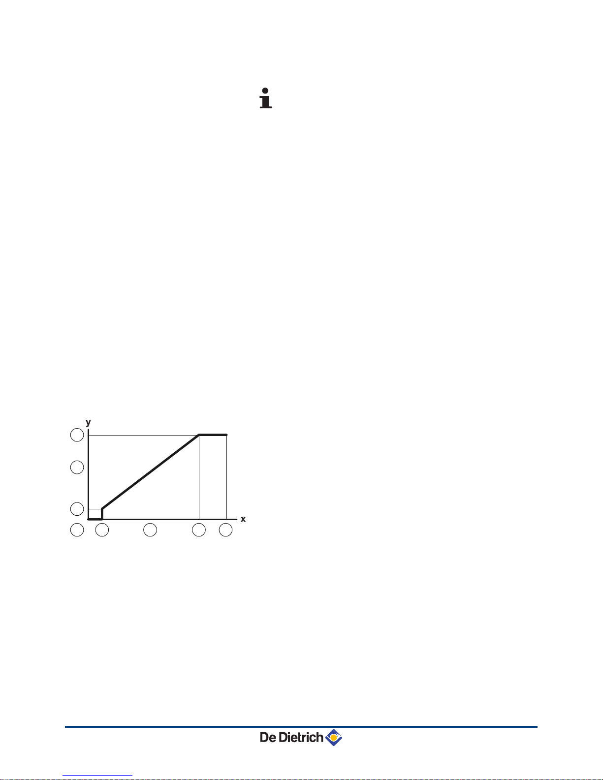
n
NIGHT
This parameter is displayed if at least one circuit does not
include a room sensor.
For circuits without a room sensor:
4 NIGHT
:DEC. (Reduced): The reduced temperature is maintained
during reduced periods. The circuit pump operates constantly.
4 NIGHT :STOP (Stop): Heating is shut down during reduced
periods. When installation antifreeze is active, the reduced
temperature is maintained during reduced periods.
For circuits with a room sensor:
4 When the room temperature is lower than the room sensor set
point: The reduced temperature is maintained during reduced
periods. The circuit pump operates constantly.
4 When the room temperature is higher than the room sensor set
point: Heating is shut down during reduced periods. When
installation antifreeze is active, the reduced temperature is
maintained during reduced periods.
n
Function 0-10 V
This function controls the boiler using an external system that
includes a 0-10 V output connected to the 0-10 V input. This command
imposes a temperature or output instruction on the boiler. It will be
necessary to ensure that the parameter BOILER MAX is higher than
CONS.MAX 0-10V.
1
Instruction set outlet temperature (°C)
2
Power input signal (V) - DC
3
0 V
4 CONS.MIN 0-10V
5 CONS.MAX 0-10V
6 VMIN/OFF 0-10V
7 VMAX 0-10V
8
10 V
x
Voltage at input
y
Boiler temperature / Boiler output
If the input voltage is less than VMIN/OFF 0-10V, the boiler is off.
The boiler temperature setting corresponds strictly to the
0-10 V
input. The secondary boiler circuits continue to operate but have no
impact on the water temperature in the boiler. If using the 0-10 V input
and a secondary boiler circuit, the external regulator providing this
0-10 V power supply must always request a temperature at least
equal to the needs of the secondary circuit.
M001679-A
5
1
4
3 6 2 7 8
5. Start-up - DIEMATIC iSystem MCA 45 - 65 - 90 - 115
80
06/09/2010 - 300024755-001-A

5.7.4. Configuring the network
1. Access the "installer" level: Press key - for around 5 seconds.
2.
Select the menu #NETWORK.
4 Turn the rotary button to scroll through the menus or
modify a value.
4 Press the rotary button to access the menu selected
or confirm a value modification.
¼
For a detailed explanation of menu browsing, refer
to the chapter: "Browsing in the menus", page
58
3. To set the following parameters:
"Installer" level - #NETWORK menu
(1)
Parameter Adjustment range Description Factory setting Customer
setting
CASCADE:
ON / NO ON: System in cascade
NO
MASTER CONTROLLER
(2)
ON / NO Configure this control system as
master on the bus
ON
SYSTEM NETWORK
(3)
Specific menu: Enlist generators or
VMs in cascade mode (See following
chapter: "Connecting appliances in
cascade")
FUNCT
(3)
CLASSIC
Operation in cascade: Successive
triggering of the various boilers in the
cascade according to requirements
CLASSIC
PARALLEL
Functioning in parallel cascade: If the
outside temperature is lower than the
value PARALLEL.CASC, all of the
boilers
are started up at the same time
PARALLEL CASC.
(4)
-10 to 20 °C Outside temperature triggering all
stages in parallel mode
10 °C
TEMP.P.GENE.CASC
(4)
0 to 30 min Minimum duration of post-operation of
the generator pump
0 mn
INTER STAGE TIMER
(2)
1 to 30 min Time delay for starting up or shutting
down generators.
4 mn
SLAVE NUMBER
(5)
2 to 10 Set the network address of the
secondary generator
2
3WW PLC
Specific menu (Not used)
InOne SCENARIO
Specific menu: Configure the InOne
scenarios to be managed by the
SCU
PCB (See following chapter:
"Configuring the scenarios")
REMOVE DEVICE
Specific menu: see below
(1) The menu is displayed only if the INSTALLATION parameter is set to EXTENDED
(2)
The parameter is only displayed if CASCADE is set to YES
(3) The parameter is displayed only if MASTER CONTROLER is set to YES
(4) The parameter is only displayed if FUNCT is set to PARALLEL
(5) The parameter is displayed only if MASTER CONTROLER is set to OFF
1
1
2
2
r
c
STD
(
'
t
v
0 2 4 6 8 10 12 14 16 18 22 2420
p
b
AUTO
x
c
r
j
M
g
m
SUNDAY 11:45
5
"
TEMP.: 68°
C002235-F-04
MCA 45 - 65 - 90 - 115 5. Start-up - DIEMATIC iSystem
06/09/2010 - 300024755-001-A
81

n
Connecting appliances in cascade
It is possible, in a cascade configuration, to enlist generators and/or
VMs as slaves. Proceed as follows:
1.
Set CASCADE to YES by pressing the rotary button and then
turning and pressing it again to confirm.
2. Select SYSTEM NETWORK and press the rotary button to go to
the specific menu.
3. To add a slave appliance to the network, select ADD SLAVE.
4. The screen displayed allows you to choose numbers for the slave
boilers to be added to the network. Numbers 2 to 10 are dedicated
to the generators and numbers 20 to 39 to the VM. Turn the rotary
button to scroll through the numbers and press to confirm the
number chosen. Press j to go back to the previous list.
5. To remove a slave appliance from the network, select ERASE
NETWORK.
6. The screen displayed allows you to choose the numbers of the
slave boilers to be removed from the network. Turn the rotary
button to scroll through the numbers and press to remove the
number chosen. Press j to go back to the previous list.
1
1
2
2
r
c
STD
(
'
t
v
0 2 4 6 8 10 12 14 16 18 22 2420
p
b
AUTO
x
c
r
j
L
g
m
CASCADE
MASTER CONTROLER
SYSTESYSTEM NETWORK
MNETZ
FUNCT
INTER STAGE TIMER
ON
ON
TRADITIONAL
4'
ÿ
C002409-B-04
1
1
2
2
r
c
STD
(
'
t
v
0 2 4 6 8 10 12 14 16 18 22 2420
p
b
AUTO
x
c
r
j
L
g
m
NB.NETWORK ELEMENTS
ADD SLAVE
ERASE NETWORK
4
ÿ
C002410-B-04
1
1
2
2
r
c
STD
(
'
t
v
0 2 4 6 8 10 12 14 16 18 22 2420
p
b
AUTO
x
c
r
j
L
g
m
SKLAVE ADDIEREN
GENE: 2, 5,
VM: 29,
4
ÿ
C002412-A-04
1
1
2
2
r
c
STD
(
'
t
v
0 2 4 6 8 10 12 14 16 18 22 2420
p
b
AUTO
x
c
r
j
L
g
m
ERASE NETWORK
GENE: 2, 5,
VM: 29,
4
ÿ
C002413-A-04
5. Start-up - DIEMATIC iSystem MCA 45 - 65 - 90 - 115
82
06/09/2010 - 300024755-001-A

7. Select NUMB.ELEMENTS.NETWORK. This screen summarises
the elements in the network recognised by the system.
Press
j
to go back to the previous list.
n
Configuring the scenarios
It is possible to choose a scenario and allocate it to various IOBL units
via the carrier current. Proceed as follows:
1. In the menu #NETWORK, select InOne SCENARIO.
2. Choose a number to allocate to the scenario by turning the rotary
button; up to 4 scenarios can be saved. To confirm, press the
rotary button.
3. Choose the desired scenario by turning the rotary button and then
confirm.
Scenarios available Description
HOLIDAYS ON
Holiday mode active (all circuits)
HOLIDAYS OFF
Holiday mode inactive (all circuits)
OUT.AUX ON
Aux outlet enabled
OUT.AUX OFF
Aux outlet disabled
DHW DAY
DHW in day mode
DHW NIGHT
DHW in night mode
DEFAULT ON
Default active
DEFAULT OFF
No active default
INPUT TEL.ON
Telephone input active
INPUT TEL.OFF
Telephone input not active
1
1
2
2
r
c
STD
(
'
t
v
0 2 4 6 8 10 12 14 16 18 22 2420
p
b
AUTO
x
c
r
j
L
g
m
NB.NETWORK ELEMENTS
GENE: 2, 5,
VM: 29,
4
ÿ
C002411-B-04
1
1
2
2
r
c
STD
(
'
t
v
0 2 4 6 8 10 12 14 16 18 22 2420
p
b
AUTO
x
c
r
j
L
g
m
INTER STAGE TIMER
3WW PLC
InOne SCENARIO
REMOVE DEVICE
4'
ÿ
C002414-B-04
1
1
2
2
r
c
(
t
v
0 2 4 6 8 10 12 14 16 18 22 2420
p
b
AUTO
x
c
r
j
L
g
m
SCENARIO
"Please choose the scenario to define"
1
ÿ
C002415-A-04
1
1
2
2
r
c
(
t
v
0 2 4 6 8 10 12 14 16 18 22 2420
p
b
AUTO
x
c
r
j
L
g
m
Configure the scenario
HOLIDAYS ON
ÿ
C002416-A-04
MCA 45 - 65 - 90 - 115 5. Start-up - DIEMATIC iSystem
06/09/2010 - 300024755-001-A
83

4. Enlist the various InOne units that have to abide by the scenario
and confirm by pressing the rotary button.
n
Removing a device
To remove a device, proceed as follows:
1.
In the menu #NETWORK, select REMOVE DEVICE.
2. Choose the device to be removed by turning the rotary button and
pressing to confirm.
n
Controlling the boiler from an IOBL Scenario Switch
It is possible to control the boiler from a scenario switch (the boiler is
then considered a slave boiler). Proceed as follows:
1. Remove the cover from the IOBL scenario switch to access the
LEARN key.
1
1
2
2
r
c
(
t
v
0 2 4 6 8 10 12 14 16 18 22 2420
p
b
AUTO
x
c
r
j
L
g
m
"Integrate the differents InOneactors.
Press on the button to finish"
C002417-A-04
1
1
2
2
r
c
STD
(
'
t
v
0 2 4 6 8 10 12 14 16 18 22 2420
p
b
AUTO
x
c
r
j
L
g
m
INTER STAGE TIMER
3WW PLC
InOne SCENARIO
REMOVE DEVICE
4'
ÿ
C002419-B-04
1
1
2
2
r
c
(
t
v
0 2 4 6 8 10 12 14 16 18 22 2420
p
b
AUTO
x
c
r
j
L
g
m
"Select the InOne device to remove"
MASTER CONTROLER
ÿ
C002420-B-04
C002421-B
5. Start-up - DIEMATIC iSystem MCA 45 - 65 - 90 - 115
84
06/09/2010 - 300024755-001-A
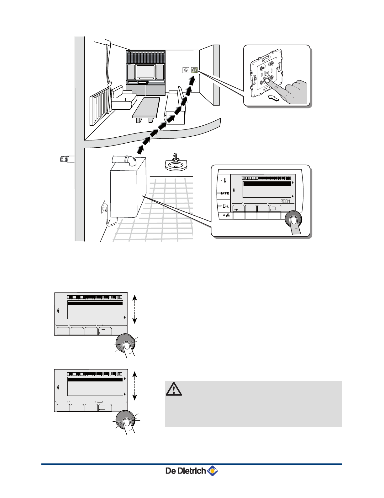
C002422-B-04
230V
230V
bar
1
1
2
2
r
c
STD
(
'
t
v
0 2 4 6 8 10 12 14 16 18 22 2420
p
b
AUTO
x
c
r
j
M
g
m
"An external devicetries to connect,
do you want to authorize it?"
LEARN ? YES
2. Press the LEARN key and the control key used to pilot the
scenario. A pairing signal is sent to the boiler by carrier current,
which displays the following message on the control panel:
"A device is trying to connect, do you want to allow this?
"
3. Set the display to YES by turning the rotary button and pressing
to confirm.
4. Choose the circuit used to run the scenario by turning the rotary
button and pressing to confirm.
CAUTION
If one of the SCU PCBs is not correctly paired, the
following message appears:
"NB not all of the SCUs are recognised
".
Start the pairing procedure again.
1
1
2
2
r
c
STD
(
'
t
v
0 2 4 6 8 10 12 14 16 18 22 2420
p
b
AUTO
x
c
r
j
L
g
m
LEARN ?
"An external devicetries to connect,
do you want to authorize it?"
YES
C002423-A-04
YES
ÿ
1
1
2
2
r
c
STD
(
'
t
v
0 2 4 6 8 10 12 14 16 18 22 2420
p
b
AUTO
x
c
r
j
L
g
m
CHOICE THE CIRC. B
C002424-B-04
ÿ
MCA 45 - 65 - 90 - 115 5. Start-up - DIEMATIC iSystem
06/09/2010 - 300024755-001-A
85
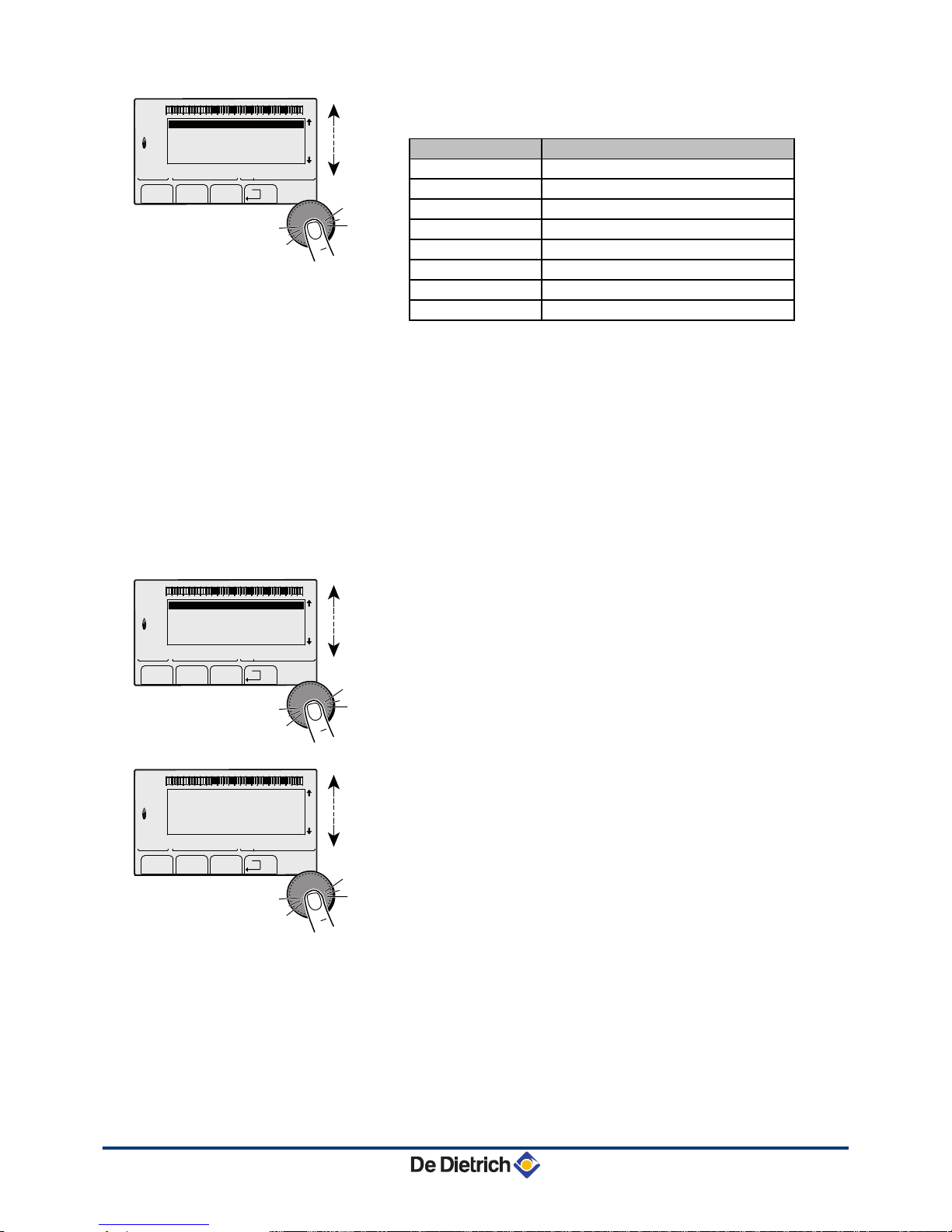
5. Choose
the desired scenario by turning the rotary button and then
confirm.
Scenarios available Description
AUTO
Heating according to the time programme
DAY
Comfort mode
NIGHT
Reduced mode
HOLIDAYS
Holiday mode
P1 Programme P1 chosen
P2 Programme P2 chosen
P3 Programme P3 chosen
P4 Programme P4 chosen
6. Terminate pairing by pressing the LEARN key on the IOBL
scenario switch.
n
Erasing a scenario from the IOBL Scenario Switch
It is possible to remove a scenario using the IOBL scenario switch.
Proceed as follows:
1. Press
the LEARN key on the scenario switch, then the control key
that pilots the scenario to be erased. A message asking whether
you wish to erase the scenario is displayed on the control panel
interface.
2. Set the display to YES by turning the rotary button and pressing
to confirm.
3. Confirm removal by pressing the LEARN key on the IOBL scenario
switch.
1
1
2
2
r
c
STD
(
'
t
v
0 2 4 6 8 10 12 14 16 18 22 2420
p
b
AUTO
x
c
r
j
L
g
m
FUNCTION :
"Function of the scenario"
HOLIDAYS
C002425-A-04
ÿ
1
1
2
2
r
c
STD
(
'
t
v
0 2 4 6 8 10 12 14 16 18 22 2420
p
b
AUTO
x
c
r
j
L
g
m
REMOVE?
Scene reset
yes
C002426-A-04
ÿ
1
1
2
2
r
c
STD
(
'
t
v
0 2 4 6 8 10 12 14 16 18 22 2420
p
b
AUTO
x
c
r
j
L
g
m
CONFIRM:
"Please close the procedure with LEARN
on the scenario switch"
C002427-A-04
ÿ
5. Start-up - DIEMATIC iSystem MCA 45 - 65 - 90 - 115
86
06/09/2010 - 300024755-001-A

5.7.5. Return to the factory settings
To reset the appliance, proceed as follows:
1.
Press key C, > and j simultaneously for 4 seconds. The menu
#RESET is displayed.
2. To set the following parameters:
#RESET menu
Choice of generator Parameter Description
GENERATOR RESET TOTAL
Performs a TOTAL RESET of all parameters
EXCEPT PROG.
Performs a parameter RESET but retains the timer programmes
PROG.
Performs a RESET on the timer programmes but retains the parameters
IOBL
Resets the system's network connections
SENSOR SCU
Performs a RESET of the generator sensors connected
ROOM SENSOR
Performs a RESET of the room sensors connected
After reset (TOTAL RESET and RESET EXCEPT PROG.), the
control system goes back to the display of the language choice after
a few seconds.
1.
Select the desired language by turning the rotary button.
2. To confirm, press the rotary button.
bar
1
1
2
2
r
c
STD
(
'
t
v
0 2 4 6 8 10 12 14 16 18 22 2420
p
b
AUTO
x
c
r
j
M
g
m
MODE
SUNDAY 11:45
C002296-B-04
4"
+ +
Français - Deutsch - English Italiano - Espanol - Nederlands
- Polski -
bar
1
1
2
2
r
c
STD
(
'
t
v
0 2 4 6 8 10 12 14 16 18 22 2420
p
b
x
c
r
g
m
a
LANGUE FRANCAIS
C003079-A
MCA 45 - 65 - 90 - 115 5. Start-up - DIEMATIC iSystem
06/09/2010 - 300024755-001-A
87

6 Start-up - IniControl
6.1 Control panel
6.1.1. Description of the keys
A
Return button j, Escape G or Manual reset t
B
Heating temperature button d or [-]
C
DHW temperature button r or [+]
D
S [Enter] Key
E
) [Chimney-sweeping] keys
Press keys A and B simultaneously
F
f [Menu] keys
Press keys C and D simultaneously
-
)
L
m
r
r
ddd
T
y
1
2
SERVICE
°C°Fh
barPsi
% rpm
kW uA
x10 l/min
°CSt:
C002968-D
t
h
j
A B
E F
C D
6. Start-up - IniControl MCA 45 - 65 - 90 - 115
88
06/09/2010 - 300024755-001-A

6.1.2. Description of the display
n
Key functions
G
Back to the previous level without saving the
modifications made
t
Manual reset
d
Central heating function:
Access to the max. heating temperature parameter.
[-]
To reduce a value
r
Sanitary hot water function:
Access to sanitary hot water temperature parameter.
[+]
To increase a value
®
Access the menu selected or confirm a value modification
n
Operating modes
d
State heating pump A
D
Heating programme deactivated:
The heating function is deactivated
r
State DHW pump
m
Manual mode
n
Flame output level
e
Low output level 0 - 25 %
r
Average output level 25 - 50 %
t
High output level 50 - 75 %
y
Output level 75 - 100 %
-
)
L
m
r
r
ddd
T
y
1
2
SERVICE
°C°Fh
barPsi
% rpm
kW uA
x10 l/min
°CSt:
C003042-B
t
h
j
-
)
L
m
r
r
ddd
T
y
1
2
SERVICE
°C°Fh
barPsi
% rpm
kW uA
x10 l/min
°CSt:
C003043-B
t
h
j
-
)
L
m
r
r
ddd
T
y
1
2
SERVICE
°C°Fh
barPsi
% rpm
kW uA
x10 l/min
°CSt:
C003044-B
t
h
j
-
)
L
m
r
r
ddd
T
y
1
2
SERVICE
°C°Fh
barPsi
% rpm
kW uA
x10 l/min
°CSt:
C003046-B
t
h
j
MCA 45 - 65 - 90 - 115 6. Start-up - IniControl
06/09/2010 - 300024755-001-A
89

n
System pressure
bar
Pressure indicator:
The
symbol is displayed next to the installation's pressure
value. If no water pressure sensor is connected, -.appears on the display
n
Other information
"
User menu:
Parameters at user level can be changed
!
Information menu:
Reading the various current values
)
Chimney-sweeping position:
Forced full or part load for CO2 measurement
-
Service menu:
Parameters at installer level can be changed
K
Display with the symbols:
$ + K + Z (Maintenance message
)
\
Hour counter menu:
Readout of the operating hours, number of successful
starts and hours on mains supply
a
On/Off switch:
After 5
lock-outs, the device must be switched off/on again
I
Outside temperature sensor present
M
The symbol is displayed when the boiler pump is
operating
a
Fault:
Boiler
indicates a fault. This is signalled by a P or X code
and a flashing display
6.2 Check points before commissioning
6.2.1. Preparing the boiler for commissioning
WARNING
Do not put the boiler into operation if the supplied gas is
not in accordance with the approved gas types.
Preparatory procedure for boiler commissioning:
4 Check
that the gas type supplied matches the data shown on the
boiler's data plate.
-
)
L
m
r
r
ddd
T
y
1
2
SERVICE
°C°Fh
barPsi
% rpm
kW uA
x10 l/min
°CSt:
C003047-C
t
h
j
-
)
L
m
r
r
ddd
T
y
1
2
SERVICE
°C°Fh
barPsi
% rpm
kW uA
x10 l/min
°CSt:
C003048-B
t
h
j
6. Start-up - IniControl MCA 45 - 65 - 90 - 115
90
06/09/2010 - 300024755-001-A

4 Check the gas circuit.
4 Check the hydraulic circuit.
4 Check the water pressure in the heating system.
4 Check the electrical connections to the thermostat and the other
external controls.
4 Check the other connections.
4 Test the boiler at full load. Check the setting of the gas/air ratio
and, if necessary, correct it.
4 Test the boiler at part load. Check the setting of the gas/air ratio
and, if necessary, correct it.
4 Finalizing work.
6.2.2.
Gas circuit
WARNING
Ensure that the boiler is switched off.
1. Open the main gas supply.
2. Unscrew
the two screws located under the front panel by a quarter
turn and remove the panel.
3. Tilt the control box forwards by opening the holding clips located
at the sides.
4. Check the gas supply pressure at the measurement point C on the
gas valve unit.
WARNING
¼
To ascertain the gas types permitted, see chapter:
"Equipment categories", page
8
5. Check the tightness of the gas connections made after the gas
valve unit in the boiler.
6.
Check the leak tightness of the gas inlet, including the gas
valves. The test pressure must not exceed 60 mbar.
7. Purge the gas supply pipe within the boiler by unscrewing the
measurement point on the gas block. Tighten the measurement
point when the pipe has been sufficiently purged.
8. Check the tightness of the gas connections in the boiler.
6.2.3. Hydraulic circuit
4 Check the syphon — this must be completely filled with clean
water.
4 Check that there are no leaks on the hydraulic connections.
6.2.4.
Electrical connections
4 Check the electrical connections.
T003243-A
C C
MCA 45 - 65 - 90 - 115 6. Start-up - IniControl
06/09/2010 - 300024755-001-A
91

6.3 Putting the appliance into operation
WARNING
If adapting to another gas type i.e. propane, the gas valve
must be adjusted before switching on the boiler.
¼ See chapter: "Adapting to another gas type", page
93
1. Tilt the control box upwards again and fasten it using the clips
located at the sides.
2.
Open the main gas supply.
3. Open the gas valve on the boiler.
4. Turn on the boiler using the on/off switch.
5. Set the controls (thermostats, control system) so that they request
heat.
6. The start-up cycle begins and cannot be interrupted. During the
start-up cycle, the display shows the following information:
A short test where all segments of the display are visible.
fK[xx
: Software version
pK[xx
: Parameter version
The version numbers are displayed alternately.
7. A vent cycle of a duration of around 3 minutes is carried out
automatically.
If a DHW sensor is connected and the anti-legionella
function is activated, the boiler starts to heat the water in
the DHW tank as soon as the vent programme has been
completed.
By pressing the ®
key for a short time, the current operating status
is shown on the display:
Heat demand d
Heat demand stopped
1 : Fan ON 1 : Post-ventilation
" : Boiler is igniting 5 : Burner stop
6 : Post-circulation of the pump
3 : Heating System 0 : Standby
In addition to 0,
in STAND-BY the display normally shows the water
pressure and the symbols d, 5tH and r.
Error during the start-up procedure:
4 No information is shown on the display:
- Check the mains supply voltage
- Check the main fuses
- Check the fuses on the control panel:
(F1 = 6,3 AT, F2 = 2 AT)
- Check the connection of the mains lead to the connector X1 in
the instrument box
4 A fault is indicated on the display by the fault symbol a and a
flashing fault code.
- The meaning of the error codes is given in the error table.
- Press for 3 seconds on key J to restart the boiler.
6. Start-up - IniControl MCA 45 - 65 - 90 - 115
92
06/09/2010 - 300024755-001-A

If the economy setting (eco setting) is on, then, after central
heating operation, the boiler will not start to run for hot tap
water production.
6.4 Gas settings
6.4.1. Adapting to another gas type
WARNING
Only a qualified engineer may carry out the following
operations.
The boiler is preset in the factory to operate on natural gas H (G20).
For operation on another group of gases, carry out the following
operations.
In case of functioning on propane:
1.
Boiler type For conversion to propane
MCA 45 Rotate the adjusting screw A on the venturi 4¾ turns in a
clockwise direction
MCA 65 Rotate the adjusting screw A on the venturi 6½ turns in a
clockwise direction
MCA 90 Fit the gas restrictor in the gas block
MCA 115 First turn the setting screw A
clockwise until it is closed, then:
Rotate the adjusting screw A on the gas block 3,5 - 4 turns in
an anticlockwise direction
2. Regulate the fan speed as indicated in the table (if required). The
setting can be modified using parameters
p17, p18
,
p19
and
p20
:
¼
See chapter: "Description of the parameters", page 100
3. Set the air/gas ratio. For more detailed information on this subject,
see the following paragraphs:
¼
"Setting the air/gas ratio (Full load)", page 93
¼
"Setting the air/gas ratio (Part load)", page 94
6.4.2. Setting the air/gas ratio (Full load)
1. Unscrew the plug of the flue gas measurement point.
2.
Connect the flue gas analyser.
WARNING
Ensure that the opening around the sensor is completely
sealed when taking measurements.
T003241-A
A A
T001581-A
MCA 45 - 65 - 90 - 115 6. Start-up - IniControl
06/09/2010 - 300024755-001-A
93

3. Set
the boiler to full load. Press keys A and B simultaneously. The
display shows
h3
. The symbol ) appears.
4. Measure the percentage of O2 or CO2 in the flue gases.
5. Compare the values measured with the checking values given in
the table (Front panel removed).
6. If necessary, adjust the gas/air ratio using the adjusting screw
(A).
O2/CO2 control and setting values for gas
H (G20) at full load
Boiler type Setting value Checking value
O 2 (%) CO 2 (%) O 2 (%) CO 2 (%)
MCA 45 4,8 ± 0,2 9,0 ± 0,1 4,8 ± 0,5 9,0 ± 0,2
MCA 65 4,8 ± 0,2 9,0 ± 0,1 4,8 ± 0,5 9,0 ± 0,2
MCA 90 3,9 ± 0,2 9,5 ± 0,1 3,9 ± 0,5 9,5 ± 0,2
MCA 115 4,7 ± 0,2 9,1 ± 0,1 4,7 ± 0,5 9,1 ± 0,2
O2/ CO2 control and setting values for propane (
G31) at full load
Boiler type Setting value Checking value
O 2 (%) CO 2 (%) O 2 (%) CO 2 (%)
MCA 45 4,6 ± 0,2 10,7 ± 0,1 4,6 ± 0,5 10,7 ± 0,2
MCA 65 4,6 ± 0,2 10,7 ± 0,1 4,6 ± 0,5 10,7 ± 0,2
MCA 90 4,6 ± 0,2 10,7 ± 0,1 4,6 ± 0,5 10,7 ± 0,2
MCA 115 4,9 ± 0,2 10,5 ± 0,1 4,9 ± 0,5 10,5 ± 0,2
6.4.3. Setting the air/gas ratio (Part load)
1. Unscrew the plug of the flue gas measurement point.
2. Connect the flue gas analyser.
WARNING
Ensure that the opening around the sensor is completely
sealed when taking measurements.
3. Set the boiler to part load. Press the [-] key several times until
l2
is displayed on the screen.
4.
Measure the percentage of O2 or CO2 in the flue gases.
5. Compare the values measured with the checking values given in
the table (Front panel removed).
)
L
d
y
1
2
bar
C003056-A
h
j
T003241-A
A A
T001581-A
)
L
d
y
1
2
bar
C003057-B
h
j
6. Start-up - IniControl MCA 45 - 65 - 90 - 115
94
06/09/2010 - 300024755-001-A

6. If necessary, adjust the gas/air ratio using the adjusting screw
(B).
O2/CO2 control and setting values for gas H (G20) at low speed
Boiler type Setting value Checking value
O 2 (%) CO 2 (%) O 2 (%) CO 2 (%)
MCA 45 4,8 ± 0,2 9,0 ± 0,1 4,8 ± 0,5 9,0 ± 0,2
MCA 65 4,8 ± 0,2 9,0 ± 0,1 4,8 ± 0,5 9,0 ± 0,2
MCA 90 3,9 ± 0,2 9,5 ± 0,1 3,9 ± 0,5 9,5 ± 0,2
MCA 115 4,3 ± 0,2 9,3 ± 0,1 4,3 ± 0,5 9,3 ± 0,2
O2/CO2 control and setting values for propane (
G31) at low speed
Boiler type Setting value Checking value
O 2 (%) CO 2 (%) O 2 (%) CO 2 (%)
MCA 45 4,6 ± 0,2 10,7 ± 0,1 4,6 ± 0,5 10,7 ± 0,2
MCA 65 4,6 ± 0,2 10,7 ± 0,1 4,6 ± 0,5 10,7 ± 0,2
MCA 90 4,6 ± 0,2 10,7 ± 0,1 4,6 ± 0,5 10,7 ± 0,2
MCA 115 4,9 ± 0,2 10,5 ± 0,1 4,9 ± 0,5 10,5 ± 0,2
6.5 Checks and adjustments after commissioning
6.5.1. Setting the heating curve
1. Press the two keys f simultaneously and then key [+] until the
symbol a flashes on the menu bar.
2.
Select the installers menu using the key S.
c0de
appears
on the display.
3. Use keys [-] or [+] to input the installer code
0012
.
4. Press key [+] until the symbol - is displayed.
5. Press the [+] key until
5[3
is displayed
T003242-A
B B
B
MCA 45 - 65 - 90 - 115 6. Start-up - IniControl
06/09/2010 - 300024755-001-A
95

n
Heating curve without BCT
A
Maximum temperature of the circuit P1
Z
Water temperature in the circuit for an outside
temperature of 0°C
E
DAY set point on the circuit S1
R
Outside temperature for which the maximum water
temperature in the circuit is reached
T
Value of the heating curve
This value corresponds to the parameter S3
6.5.2. Finalizing work
1. Remove the measuring equipment.
2.
Put the flue gas sampling plug back in place.
3. Refit the front panel. Tighten the two screws by a quarter turn.
4. Push key j to return the boiler to normal operating mode.
5. Raise the temperature in the heating system to approximately
70°C.
6. Shut down the boiler.
7. After about 10 minutes, vent the air in the heating system.
8. Checking the hydraulic pressure. If necessary, top up the water
level in the heating system (recommended hydraulic pressure
between 1,5 and 2 bar).
9. Tick the gas category used on the data plate.
10.Explain the operation of the installation, the boiler and the
regulator to the users.
11.Inform the user of the periodicity of maintenance work to be carried
out. Input the service date and the contact details of the installer.
12.Give all the instruction manuals to the user.
Commissioning of the boiler is now complete.
The various boiler parameters are preset in the factory.
These factory settings are suitable for the most common
heating systems. For other systems and situations, the
parameters can be modified.
20 0 -16
50
75
C°
C°
1.5
C002319-B
1
2
3
4
5
T001522-A
6. Start-up - IniControl MCA 45 - 65 - 90 - 115
96
06/09/2010 - 300024755-001-A

6.6 Reading out measured values
6.6.1. Reading out measured values
The following current values can be read off the information menu
Q:
4 5t = State.
4 5v = Sub-status.
4 t1 = Flow temperature (°C).
4 t" = Return temperature (°C).
4 t3 = Calorifier temperature (°C).
4 t4 = Outside temperature (°C).
4 t5 = Solar boiler temperature
(°C).
4 5p = Internal set point (°C).
4 fl = Ionisation current (µA).
4 Mf = Fan speed in rpm.
4 pr = Water pressure (bar).
4 p; = Supplied relative heat output (%).
MCA 45 - 65 - 90 - 115 6. Start-up - IniControl
06/09/2010 - 300024755-001-A
97

The current values can be read as follows:
1.
Press the two f keys simultaneously. The symbol Q flashes.
2. Confirm using key S.
5t
is displayed, alternating with the
current status 3 (for example).
3. Press the [+] key.
5v
is displayed, alternating with the current
sub-status
30
(for example).
4. Press the [+] key.
t1
is displayed, alternating with the current
flow temperature
60
°C (for example).
5. Press the [+] key successively to scroll down the various
parameters.
t", t3, t4, t5
.
6. Press the [+] key.
5p
is displayed, alternating with the internal
set point
88
°C (for example).
7. Press the [+] key.
fl
is displayed, alternating with the current
ionisation current
70
µA (for example).
8. Press the [+] key.
Mf
is displayed, alternating with the current
fan rotation speed
3000
rpm (for example).
9. Press the [+] key.
pr
is displayed, alternating with the current
water pressure
#0
bar (for example). If no water pressure sensor
is connected, [-.-] appears on the display.
10.Press the [+] key.
p;
is displayed, alternating with the current
modulation percentage
78
% (for example).
11.Press the [+] key. The readout cycle starts again with
5t
.
12.Press 2 times on key j to return to the current operating mode.
)
r
d
bar
C003049-A
t
h
j
h
j
4x
2x
6. Start-up - IniControl MCA 45 - 65 - 90 - 115
98
06/09/2010 - 300024755-001-A
 Loading...