

DeDietrich INNOVENS PRO User And Installation Manual
PROJECT
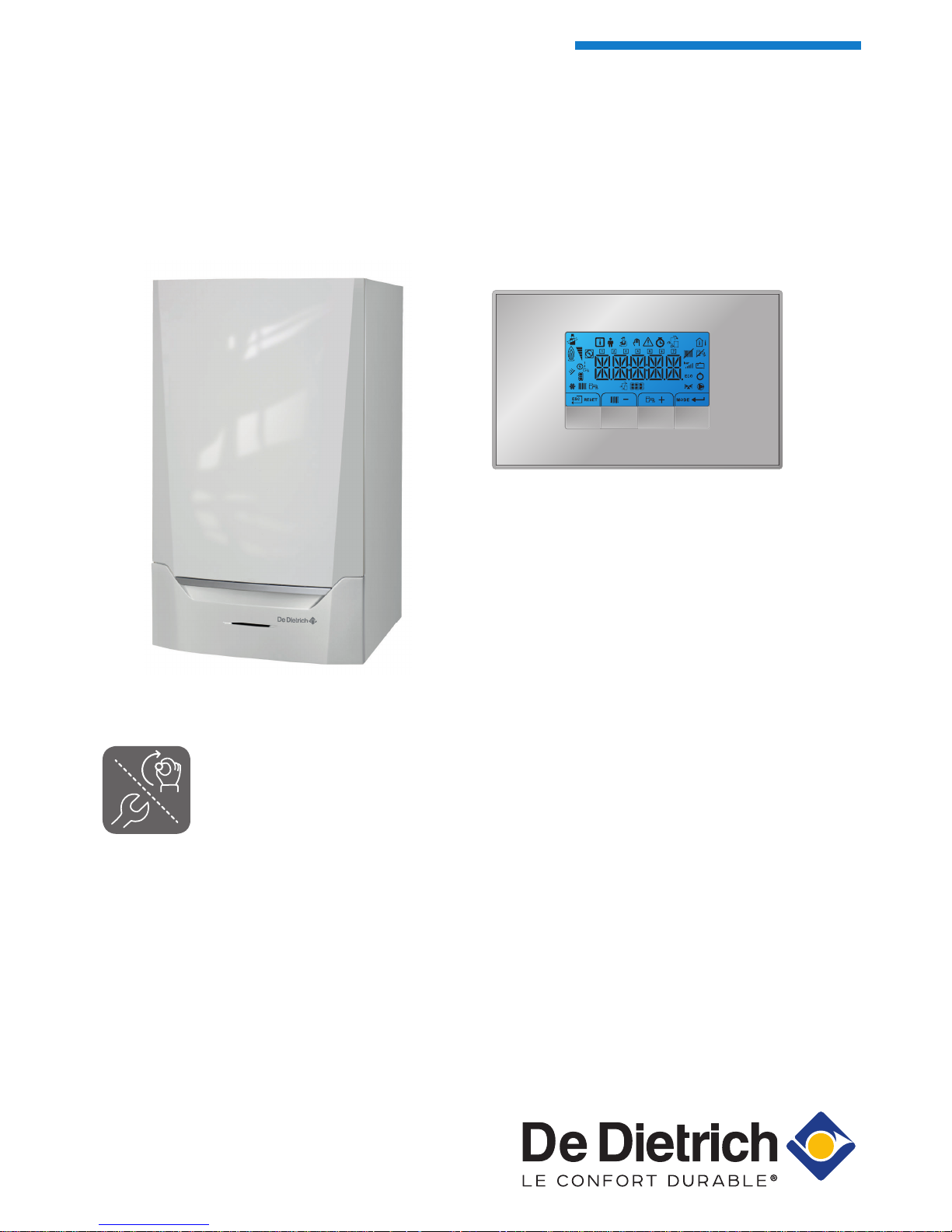
INNOVENS PRO
Ireland
en
User and Installation Manual
Control panel & Control PCB
Inicontrol 2

Contents
1 Safety . . . . . . . . . . . . . . . . . . . . . . . . . . . . . . . . . . . . . . . . . . . . . . . . . . . . . . . . . . . . . . . . . . . . . . . . . . . . . . . . . . . . . . . . . . . . 4
1.1 Liabilities . . . . . . . . . . . . . . . . . . . . . . . . . . . . . . . . . . . . . . . . . . . . . . . . . . . . . . . . . . . . . . . . . . . . . . . . . . . . . . . . . . . . . 4
1.1.1 Manufacturer's liability . . . . . . . . . . . . . . . . . . . . . . . . . . . . . . . . . . . . . . . . . . . . . . . . . . . . . . . . . . . . . . . . . . . 4
1.1.2 Installer's liability . . . . . . . . . . . . . . . . . . . . . . . . . . . . . . . . . . . . . . . . . . . . . . . . . . . . . . . . . . . . . . . . . . . . . . . 4
1.1.3 User's liability . . . . . . . . . . . . . . . . . . . . . . . . . . . . . . . . . . . . . . . . . . . . . . . . . . . . . . . . . . . . . . . . . . . . . . . . . .4
2 About this manual . . . . . . . . . . . . . . . . . . . . . . . . . . . . . . . . . . . . . . . . . . . . . . . . . . . . . . . . . . . . . . . . . . . . . . . . . . . . . . . . . . . 6
2.1 Symbols used in the manual . . . . . . . . . . . . . . . . . . . . . . . . . . . . . . . . . . . . . . . . . . . . . . . . . . . . . . . . . . . . . . . . . . . . . .6
3 Description of the product . . . . . . . . . . . . . . . . . . . . . . . . . . . . . . . . . . . . . . . . . . . . . . . . . . . . . . . . . . . . . . . . . . . . . . . . . . . . . 7
3.1 Control panel description . . . . . . . . . . . . . . . . . . . . . . . . . . . . . . . . . . . . . . . . . . . . . . . . . . . . . . . . . . . . . . . . . . . . . . . . 7
3.1.1 What each key means . . . . . . . . . . . . . . . . . . . . . . . . . . . . . . . . . . . . . . . . . . . . . . . . . . . . . . . . . . . . . . . . . . . 7
3.1.2 Meaning of the symbols on the display . . . . . . . . . . . . . . . . . . . . . . . . . . . . . . . . . . . . . . . . . . . . . . . . . . . . . . 7
3.2 Expansion board description . . . . . . . . . . . . . . . . . . . . . . . . . . . . . . . . . . . . . . . . . . . . . . . . . . . . . . . . . . . . . . . . . . . . . .8
4 User instructions . . . . . . . . . . . . . . . . . . . . . . . . . . . . . . . . . . . . . . . . . . . . . . . . . . . . . . . . . . . . . . . . . . . . . . . . . . . . . . . . . . . . 9
4.1 Use of the control panel . . . . . . . . . . . . . . . . . . . . . . . . . . . . . . . . . . . . . . . . . . . . . . . . . . . . . . . . . . . . . . . . . . . . . . . . . 9
4.1.1 Browsing in the menus . . . . . . . . . . . . . . . . . . . . . . . . . . . . . . . . . . . . . . . . . . . . . . . . . . . . . . . . . . . . . . . . . . 9
4.2 Setting the language and time . . . . . . . . . . . . . . . . . . . . . . . . . . . . . . . . . . . . . . . . . . . . . . . . . . . . . . . . . . . . . . . . . . . 10
4.2.1 Setting the language . . . . . . . . . . . . . . . . . . . . . . . . . . . . . . . . . . . . . . . . . . . . . . . . . . . . . . . . . . . . . . . . . . . 10
4.2.2 Setting the time and date . . . . . . . . . . . . . . . . . . . . . . . . . . . . . . . . . . . . . . . . . . . . . . . . . . . . . . . . . . . . . . . .10
4.3 Changing the central heating flow temperature . . . . . . . . . . . . . . . . . . . . . . . . . . . . . . . . . . . . . . . . . . . . . . . . . . . . . . 11
4.4 Changing the DHW temperature . . . . . . . . . . . . . . . . . . . . . . . . . . . . . . . . . . . . . . . . . . . . . . . . . . . . . . . . . . . . . . . . . .12
4.5 Setting the Timer Program . . . . . . . . . . . . . . . . . . . . . . . . . . . . . . . . . . . . . . . . . . . . . . . . . . . . . . . . . . . . . . . . . . . . . . 12
4.6 Changing user parameters . . . . . . . . . . . . . . . . . . . . . . . . . . . . . . . . . . . . . . . . . . . . . . . . . . . . . . . . . . . . . . . . . . . . . . 14
5 Installer instructions . . . . . . . . . . . . . . . . . . . . . . . . . . . . . . . . . . . . . . . . . . . . . . . . . . . . . . . . . . . . . . . . . . . . . . . . . . . . . . . . .16
5.1 Changing installer parameters . . . . . . . . . . . . . . . . . . . . . . . . . . . . . . . . . . . . . . . . . . . . . . . . . . . . . . . . . . . . . . . . . . . 16
5.2 Adjusting advanced parameters . . . . . . . . . . . . . . . . . . . . . . . . . . . . . . . . . . . . . . . . . . . . . . . . . . . . . . . . . . . . . . . . . . 17
5.3 Carrying out an auto-detect . . . . . . . . . . . . . . . . . . . . . . . . . . . . . . . . . . . . . . . . . . . . . . . . . . . . . . . . . . . . . . . . . . . . . 18
5.4 Restoring to factory settings . . . . . . . . . . . . . . . . . . . . . . . . . . . . . . . . . . . . . . . . . . . . . . . . . . . . . . . . . . . . . . . . . . . . . 18
5.5 Chimney sweep mode (forced full load or part load) . . . . . . . . . . . . . . . . . . . . . . . . . . . . . . . . . . . . . . . . . . . . . . . . . . 19
5.6 Connected control PCBs . . . . . . . . . . . . . . . . . . . . . . . . . . . . . . . . . . . . . . . . . . . . . . . . . . . . . . . . . . . . . . . . . . . . . . . .20
5.7 Activating the manual mode menu . . . . . . . . . . . . . . . . . . . . . . . . . . . . . . . . . . . . . . . . . . . . . . . . . . . . . . . . . . . . . . . . 20
5.8 Shutdown . . . . . . . . . . . . . . . . . . . . . . . . . . . . . . . . . . . . . . . . . . . . . . . . . . . . . . . . . . . . . . . . . . . . . . . . . . . . . . . . . . . 21
5.8.1 Switching off the central heating . . . . . . . . . . . . . . . . . . . . . . . . . . . . . . . . . . . . . . . . . . . . . . . . . . . . . . . . . . 21
5.8.2 Switching off DHW production . . . . . . . . . . . . . . . . . . . . . . . . . . . . . . . . . . . . . . . . . . . . . . . . . . . . . . . . . . . . 21
5.9 Reading out the Counter menu . . . . . . . . . . . . . . . . . . . . . . . . . . . . . . . . . . . . . . . . . . . . . . . . . . . . . . . . . . . . . . . . . . .21
5.10 Reading out current values . . . . . . . . . . . . . . . . . . . . . . . . . . . . . . . . . . . . . . . . . . . . . . . . . . . . . . . . . . . . . . . . . . . . . . 22
5.11 Status and Sub-status . . . . . . . . . . . . . . . . . . . . . . . . . . . . . . . . . . . . . . . . . . . . . . . . . . . . . . . . . . . . . . . . . . . . . . . . . .23
6 Installation . . . . . . . . . . . . . . . . . . . . . . . . . . . . . . . . . . . . . . . . . . . . . . . . . . . . . . . . . . . . . . . . . . . . . . . . . . . . . . . . . . . . . . . . 24
6.1 Electrical connections . . . . . . . . . . . . . . . . . . . . . . . . . . . . . . . . . . . . . . . . . . . . . . . . . . . . . . . . . . . . . . . . . . . . . . . . . . 24
6.1.1 Connecting status notifications . . . . . . . . . . . . . . . . . . . . . . . . . . . . . . . . . . . . . . . . . . . . . . . . . . . . . . . . . . . 24
6.1.2 Connecting 0–10 V output . . . . . . . . . . . . . . . . . . . . . . . . . . . . . . . . . . . . . . . . . . . . . . . . . . . . . . . . . . . . . . . 24
7 Operation . . . . . . . . . . . . . . . . . . . . . . . . . . . . . . . . . . . . . . . . . . . . . . . . . . . . . . . . . . . . . . . . . . . . . . . . . . . . . . . . . . . . . . . . .25
7.1 Cascade control . . . . . . . . . . . . . . . . . . . . . . . . . . . . . . . . . . . . . . . . . . . . . . . . . . . . . . . . . . . . . . . . . . . . . . . . . . . . . . 25
8 Settings . . . . . . . . . . . . . . . . . . . . . . . . . . . . . . . . . . . . . . . . . . . . . . . . . . . . . . . . . . . . . . . . . . . . . . . . . . . . . . . . . . . . . . . . . . 26
8.1 List of parameters . . . . . . . . . . . . . . . . . . . . . . . . . . . . . . . . . . . . . . . . . . . . . . . . . . . . . . . . . . . . . . . . . . . . . . . . . . . . . 26
8.1.1 Description of the parameters - Inicontrol 2 . . . . . . . . . . . . . . . . . . . . . . . . . . . . . . . . . . . . . . . . . . . . . . . . . .26
8.1.2 Description of the parameters - SCB-01 . . . . . . . . . . . . . . . . . . . . . . . . . . . . . . . . . . . . . . . . . . . . . . . . . . . . 27
8.2 List of measured values . . . . . . . . . . . . . . . . . . . . . . . . . . . . . . . . . . . . . . . . . . . . . . . . . . . . . . . . . . . . . . . . . . . . . . . . 28
8.2.1 Counters - SCB-01 . . . . . . . . . . . . . . . . . . . . . . . . . . . . . . . . . . . . . . . . . . . . . . . . . . . . . . . . . . . . . . . . . . . . 28
8.2.2 Signals - SCB-01 . . . . . . . . . . . . . . . . . . . . . . . . . . . . . . . . . . . . . . . . . . . . . . . . . . . . . . . . . . . . . . . . . . . . . . 28
8.2.3 Status and sub-status - SCB-01 . . . . . . . . . . . . . . . . . . . . . . . . . . . . . . . . . . . . . . . . . . . . . . . . . . . . . . . . . . 29
9 Troubleshooting . . . . . . . . . . . . . . . . . . . . . . . . . . . . . . . . . . . . . . . . . . . . . . . . . . . . . . . . . . . . . . . . . . . . . . . . . . . . . . . . . . . .31
9.1 Error codes . . . . . . . . . . . . . . . . . . . . . . . . . . . . . . . . . . . . . . . . . . . . . . . . . . . . . . . . . . . . . . . . . . . . . . . . . . . . . . . . . . 31
9.1.1 Warning . . . . . . . . . . . . . . . . . . . . . . . . . . . . . . . . . . . . . . . . . . . . . . . . . . . . . . . . . . . . . . . . . . . . . . . . . . . . . 31
9.1.2 Blocking . . . . . . . . . . . . . . . . . . . . . . . . . . . . . . . . . . . . . . . . . . . . . . . . . . . . . . . . . . . . . . . . . . . . . . . . . . . . . 31
9.1.3 Lock-out . . . . . . . . . . . . . . . . . . . . . . . . . . . . . . . . . . . . . . . . . . . . . . . . . . . . . . . . . . . . . . . . . . . . . . . . . . . . .31
9.2 Error memory . . . . . . . . . . . . . . . . . . . . . . . . . . . . . . . . . . . . . . . . . . . . . . . . . . . . . . . . . . . . . . . . . . . . . . . . . . . . . . . . 31
Contents
2 7667004 - v.01 - 12072017

9.2.1 Reading out the Error memory . . . . . . . . . . . . . . . . . . . . . . . . . . . . . . . . . . . . . . . . . . . . . . . . . . . . . . . . . . . 32
9.2.2 Clearing the error memory . . . . . . . . . . . . . . . . . . . . . . . . . . . . . . . . . . . . . . . . . . . . . . . . . . . . . . . . . . . . . . .32
Contents
7667004 - v.01 - 12072017 3

1 Safety
1.1 Liabilities
1.1.1 Manufacturer's liability
Our products are manufactured in compliance with the
requirements of the various Directives applicable. They
are therefore delivered with the marking and any
documents necessary. In the interests of the quality of
our products, we strive constantly to improve them. We
therefore reserve the right to modify the specifications
given in this document.
Our liability as manufacturer may not be invoked in the
following cases:
Failure to abide by the instructions on installing the
appliance.
Failure to abide by the instructions on using the appli
ance.
Faulty or insufficient maintenance of the appliance.
1.1.2
Installer's liability
The installer is responsible for the installation and initial
commissioning of the appliance. The installer must ob
serve the following instructions:
Read and follow the instructions given in the manuals
provided with the appliance.
Install the appliance in compliance with prevailing leg
islation and standards.
Carry out initial commissioning and any checks neces
sary.
Explain the installation to the user.
If maintenance is necessary, warn the user of the obli
gation to check the appliance and keep it in good
working order.
Give all the instruction manuals to the user.
1.1.3 User's liability
To guarantee optimum operation of the system, you
must abide by the following instructions:
Read and follow the instructions given in the manuals
provided with the appliance.
Call on a qualified professional to carry out installation
and initial commissioning.
Get your installer to explain your installation to you.
1 Safety
4 7667004 - v.01 - 12072017

Have the required inspections and maintenance car
ried out by a qualified installer.
Keep the instruction manuals in good condition close
to the appliance.
1 Safety
7667004 - v.01 - 12072017 5
2 About this manual
2.1 Symbols used in the manual
This manual uses various symbols to draw attention to special instructions.
We do this to improve user safety, to prevent problems and to guarantee
correct operation.
Caution
Risk of material damage.
Important
Please note: important information.
See
Reference to other manuals or pages in this manual.
2 About this manual
6 7667004 - v.01 - 12072017
3 Description of the product
The MCA boiler is delivered with a combination of the control panel and
control PCB. The combination is based on the following software and navi
gation information:
Boiler MCA
Important
Content of this manual is based on software version 0.17
Name / navigate to:
Control panel Inicontrol 2
Important
Content of this manual is based on software version 2.0
Name / navigate to:
Control PCB SCB-01
Important
Content of this manual is based on software version 0.2
Name / navigate to:
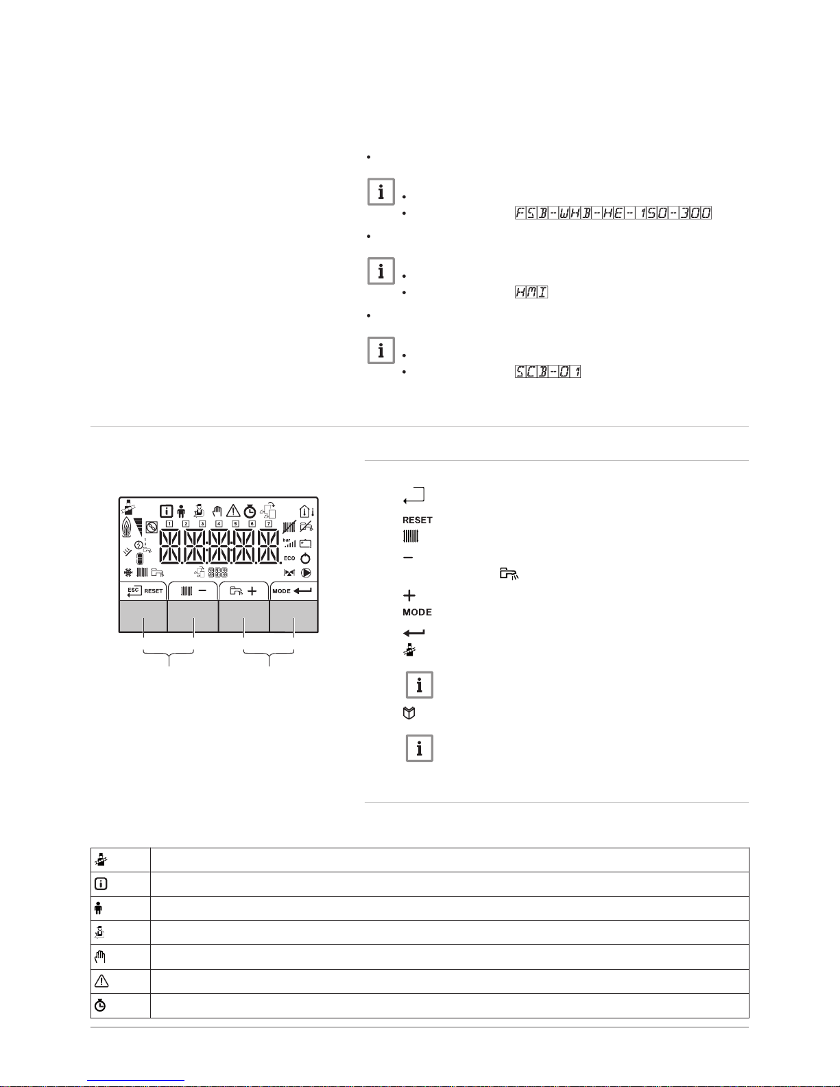
3.1 Control panel description
3.1.1 What each key means
1
h
Escape: Back to the previous level.
Reset: Manual reset.
2
CH flow temperature Access to set temperature.
Min. key: Lowering the value.
3
DHW temperature: Access to set temperature.
Plus key: Raising the value.
4
CH/DHW function: Toggles function ON/OFF
Enter key: Confirms selection or value.
5
Chimney-sweeping keys
Important
Press the 1 and 2 keys simultaneously.
6
Menu keys
Important
Press the 3 and 4 keys simultaneously.
3.1.2 Meaning of the symbols on the display
Tab.1 Possible symbols in the display (depending on available devices or functions)
Chimney sweep mode is enabled (forced full load or part load for
O2 measurement).
Information menu: read out various current values.
User menu: settings for user level parameters can be changed.
Installer menu: parameters at installer level can be changed.
Manual mode menu: manual mode can be configured.
Error menu: errors can be read out.
Hour counter/timer program/time display menu.
Fig.1 Control panel
AD-3000833-01
1 2 3 4
5 6
3 Description of the product
7667004 - v.01 - 12072017 7
Control PCB menu: (optional) control PCBs can be read out.
The outside temperature sensor is connected.
The room temperature sensor is connected.
The burner output level (1 to 5 bars, with each bar representing 20% output)
The heat pump is switched on.
-
Day display
Central heating operation is switched off.
DHW operation is switched off.
The solar boiler is on and the heat level of the boiler displayed.
Displaying the system water pressure.
The holiday program is enabled.
Frost protection operation is enabled.
Central heating operation is enabled.
DHW operation is enabled.
Displaying the selected PCB.
The three-way valve is connected.
The circulation pump is turning.
ECO mode operation is enabled.
Switch the appliance off then on again.
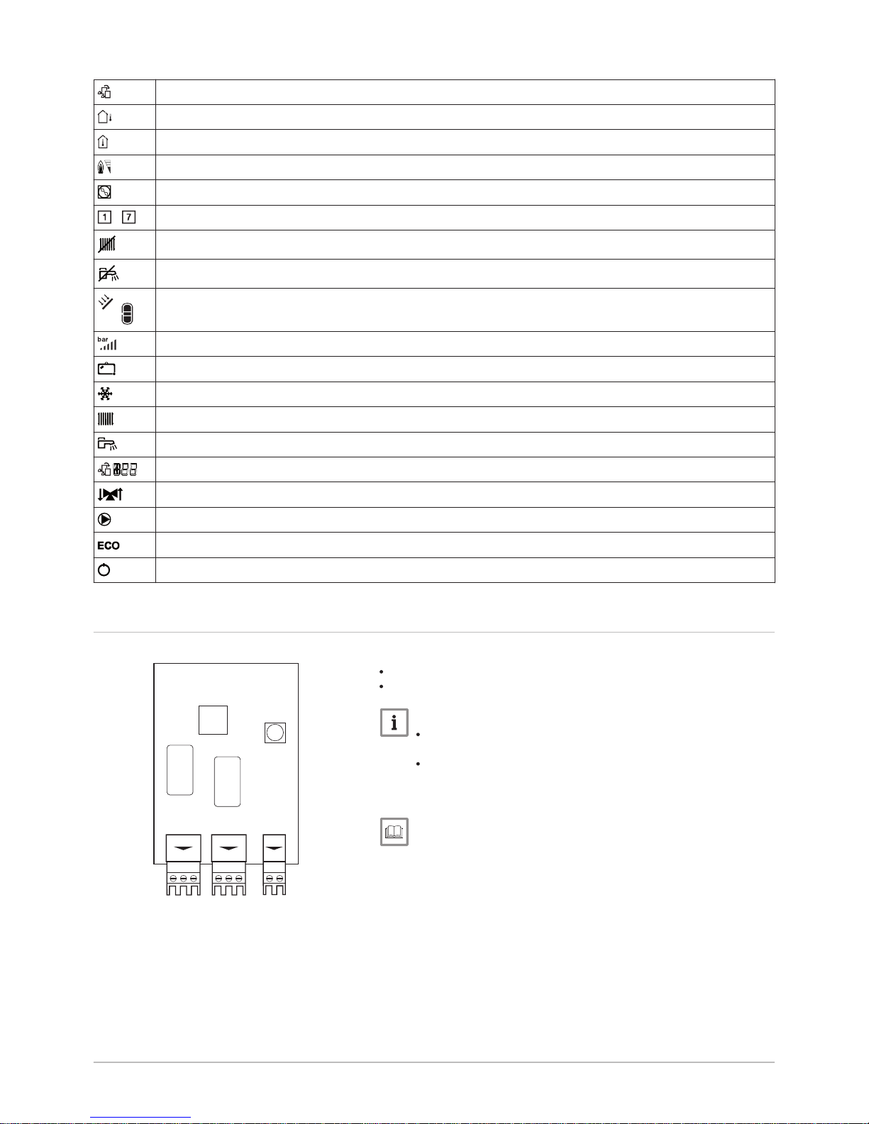
3.2 Expansion board description
The expansion board SCB-01 has the following features:
0–10 V connection for a PWM system pump
Two potential-free contacts for status notification
Important
If the boiler is fitted with the SCB-01 board, then this is automat
ically recognised by the automatic control unit of the boiler.
On removing this board, the boiler will show an error code. To
prevent this error, carry out an auto-detect immediately after re
moving this board.
For more information, see
Carrying out an auto-detect, page 18
Fig.2 SCB-01 expansion board
AD-0000660-01
Status
Nc
C No
Status
Nc
C No
+
0
0 -10
SCB-01
3 Description of the product
8 7667004 - v.01 - 12072017
4 User instructions
4.1 Use of the control panel
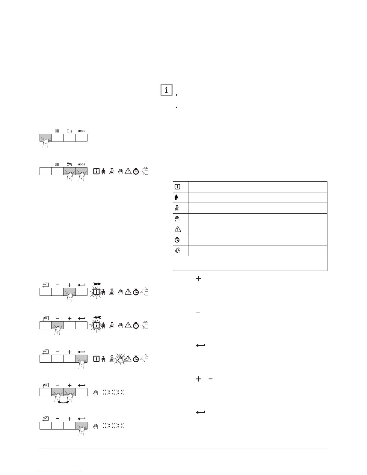
4.1.1 Browsing in the menus
Important
Depending on the devices or control PCBs connected, the con
trol panel shows selection options in some menus.
First, select a device, control PCB or zone to view or amend a
setting.
1. Press any key to activate the controller from the stand-by screen.
2. Access the available menu options by pressing the two keys on the
right simultaneously.
Tab.2 Possible menu choices
Information Menu
User menu
Installer Menu
Manual mode menu
Failure Menu
Hour Run Meters / Timer Program / Clock menu
PCB menu
(1)
(1) The icon is displayed only if an optional control PCB has been instal
led.
3. Press the key to move the cursor to the right.
4. Press the key to move the cursor to the left.
5. Press the key to confirm selection of the required menu or pa
rameter.
6. Press the or key to modify the value.
7. Press the key to confirm the value.
Fig.3 Step 1
MW-3000377-02
Fig.4 Step 2
MW-3000299-01
Fig.5 Step 3
MW-3000300-02
Fig.6 Step 4
MW-3000301-02
Fig.7 Step 5
MW-3000302-01
Fig.8 Step 6
MW-3000303-01
Fig.9 Step 7
MW-3000304-01
4 User instructions
7667004 - v.01 - 12072017 9
8. Press the h key to go back to the main display.
Important
The stand-by screen appears if no key is pressed for three mi
nutes.
4.2 Setting the language and time
Important
First set the desired language, then the correct time, day and date
before further use of the control panel.
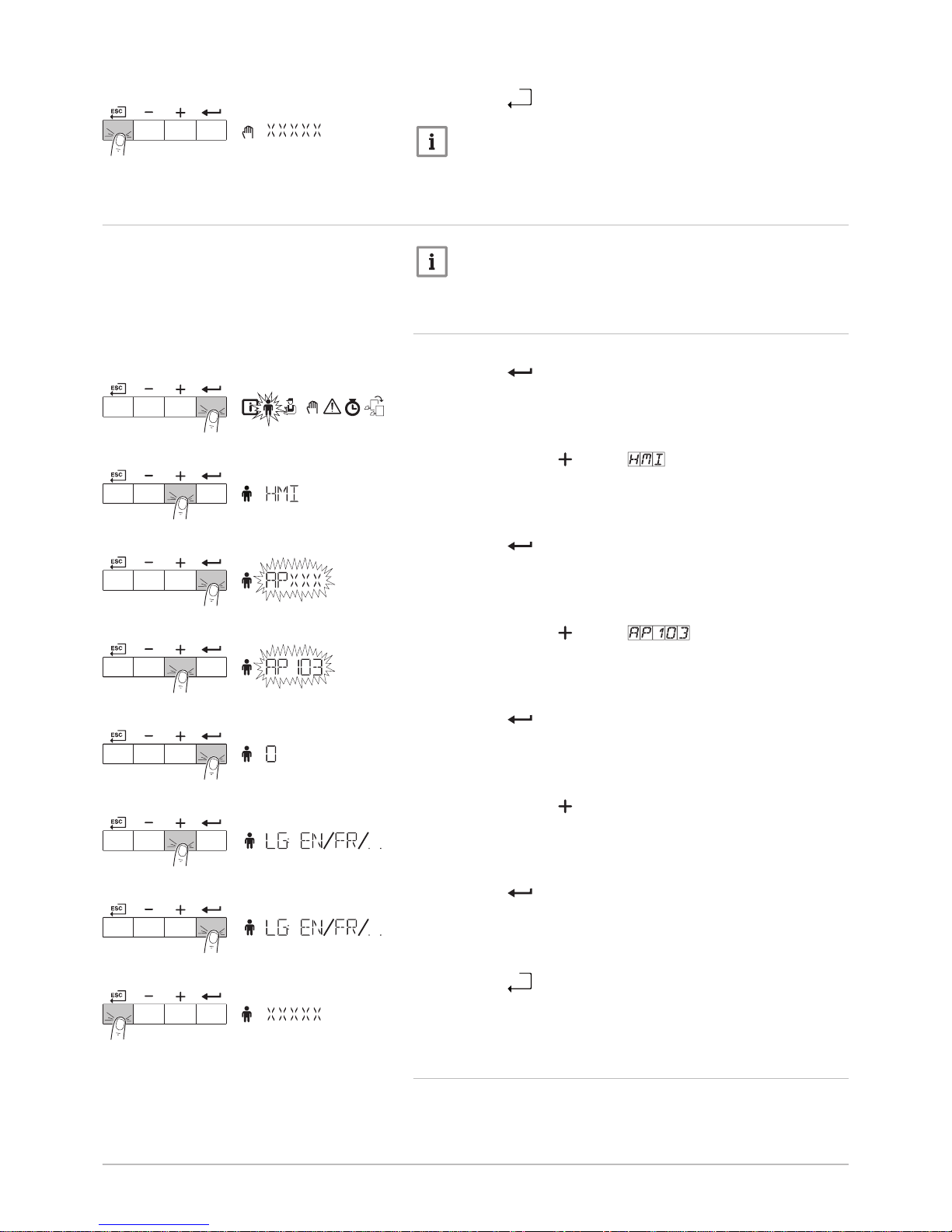
4.2.1
Setting the language
1. Navigate to the User menu.
2. Press the key to open the User menu.
3. Keep pressing the key until is displayed.
4. Press the key to confirm the selection.
5. Keep pressing the key until is displayed.
6. Press the key to confirm the parameter.
7. Keep pressing the key until the required language code is dis
played.
8. Press the key to confirm the choice of language.
9. Press the h key multiple times to go back to the main display.
4.2.2 Setting the time and date
1. Navigate to the Counter menu.
Fig.10 Step 8
MW-3000305-01
Fig.11 Step 2
MW-3000309-01
Fig.12 Step 3
MW-3000390-01
Fig.13 Step 4
MW-3000333-01
Fig.14 Step 5
MW-3000348-01
Fig.15 Step 6
MW-3000349-01
Fig.16 Step 7
MW-3000419-02
Fig.17 Step 8
MW-3000447-02
Fig.18 Step 9
MW-3000311-01
4 User instructions
10 7667004 - v.01 - 12072017
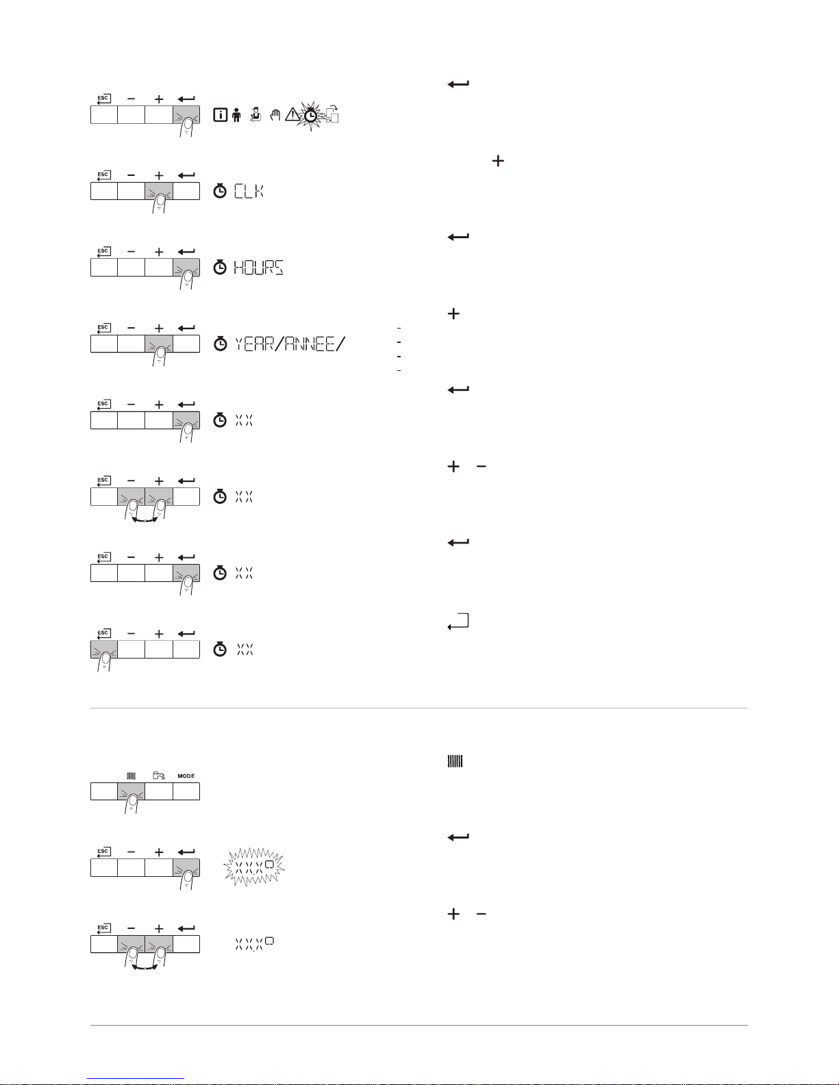
2. Press the key to open the counter menu.
3. Keep pressing the key until the Time display menu is displayed.
4.
Press the key to access the hours.
5. Press the key to access the following parameters:
Minutes
Day
Month
Year
6. Press the key to confirm the parameter.
7. Press the or key to modify the value.
8. Press the key to confirm the value.
9. Press the h key multiple times to go back to the main display.
4.3 Changing the central heating flow temperature
The central heating flow temperature can be raised or lowered separately
from the heating requirement.
1. Press the key to select the central heating flow temperature.
2. Press the key to access the central heating flow temperature.
3. Press the or key for the required CH flow temperature.
Fig.19 Step 2
MW-3000320-01
Fig.20 Step 3
MW-3000393-01
Fig.21 Step 4
MW-3000353-01
Fig.22 Step 5
MW-3000395-03
Fig.23 Step 6
MW-3000354-01
Fig.24 Step 7
MW-3000355-01
Fig.25 Step 8
MW-3000354-01
Fig.26 Step 9
MW-3000397-01
Fig.27 Step 1
MW-3000366-01
Fig.28 Step 2
MW-3000367-01
Fig.29 Step 3
MW-3000368-01
4 User instructions
7667004 - v.01 - 12072017 11
 Loading...