

DeDietrich Innovens MCA 28 BIC, Innovens MCA 25 BIC User Manual
Innovens
EN
Wall-hung gas condensing boilers
MCA 35
User Guide
300022163-001-01

Contents
1 Introduction ................................................................................................4
1.1 Symbols used .......................................................4
1.2 Abbreviations ........................................................4
1.3 General ..................................................................5
1.3.1 Manufacturer's liability .............................................5
1.3.2 Installer's liability .....................................................5
1.3.3 User's liability ..........................................................5
1.4 Certifications .........................................................6
2 Safety instructions and recommendations ..............................................7
2.1 Safety instructions ...............................................7
2.2 Recommendations ................................................8
3 Description ..................................................................................................9
3.1 Operating principle ...............................................9
3.1.1 Gas/air setting .........................................................9
3.1.2 Combustion .............................................................9
3.2 Main parts ............................................................10
3.3 Control panel .......................................................11
3.3.1 Description of the keys ..........................................11
3.3.2 Description of the display ......................................12
3.3.3 Browsing in the menus ..........................................15
4 Operating the boiler .................................................................................16
4.1 Commissioning the boiler ..................................16
4.2 Reading out measured values ...........................16
4.3 Changing the settings ........................................18
4.3.1 Setting the set point temperatures ........................18
4.3.2 Selecting the operating mode ...............................19
4.3.3 Forcing domestic hot water production .................20
4.3.4 Setting the contrast and lighting on the
display ...................................................................20
4.3.5 Setting the time and date ......................................21
4.3.6 Selecting a timer programme ................................21
4.3.7 Customising a timer programme ...........................22
1
15/06/12 - 300022163-001-01

4.4 Installation shutdown .........................................24
4.5 Frost protection ..................................................24
5 Checking and maintenance .....................................................................26
5.1 General instructions ...........................................26
5.2 Periodic checks ..................................................26
5.3 Filling the system ...............................................27
5.4 Bleeding the heating system .............................29
5.5 Draining the installation .....................................31
6 Troubleshooting .......................................................................................32
6.1 Anti-hunting ........................................................32
6.2 Messages (Code type Bxx or Mxx) ....................32
6.3 Faults (Code type Lxx or Dxx) ...........................34
7 Technical specifications ..........................................................................40
7.1 Technical specifications ....................................40
8 Energy savings .........................................................................................41
8.1 Energy-saving advice .........................................41
8.2 Recommendations ..............................................41
9 Warranty ....................................................................................................42
9.1 General ................................................................42
9.2 Warranty terms ...................................................42
Contents
2
15/06/12 - 300022163-001-01

3
15/06/12 - 300022163-001-01
1 Introduction
1.1 Symbols used
In these instructions, various danger levels are employed to draw the
user's attention to particular information. In so doing, we wish to
safeguard the user's safety, obviate hazards and guarantee correct
operation of the appliance.
DANGER
Risk of a dangerous situation causing serious physical
injury.
WARNING
Risk of a dangerous situation causing slight physical
injury.
CAUTION
Risk of material damage.
Signals important information.
¼ Signals a referral to other instructions or other pages in the
instructions.
1.2 Abbreviations
4 3CE: Collective conduit for sealed boiler
4 DHW: Domestic hot water
4 Hi: Lower heating value LHV (Nett)
4 Hs: Higher heating value HHV (Gross)
4 PPS: Polypropylene hardly inflammable
4 PCU: Primary Control Unit - PCB for managing burner operation
4 PSU: Parameter Storage Unit - Parameter storage for PCBs
PCU and SU
4 SCU: Secondary Control Unit - control panel PCB
4 SU: Safety Unit - Safety PCB
4 3WV: 3-way valve
MCA 35
1. Introduction
15/06/12 - 300022163-001-01
4

1.3 General
1.3.1. Manufacturer's liability
Our products are manufactured in compliance with the requirements
of the various applicable European Directives. They are therefore
delivered with [ marking and all relevant documentation.
In the interest of customers, we are continuously endeavouring to
make improvements in product quality. All the specifications stated in
this document are therefore subject to change without notice.
Our liability as the manufacturer may not be invoked in the following
cases:
4 Failure to abide by the instructions on using the appliance.
4 Faulty or insufficient maintenance of the appliance.
4 Failure to abide by the instructions on installing the appliance.
1.3.2. Installer's liability
The installer is responsible for the installation and inital start up of the
appliance. The installer must respect the following instructions:
4 Read and follow the instructions given in the manuals provided
with the appliance.
4 Carry out installation in compliance with the prevailing legislation
and standards.
4 Perform the initial start up and carry out any checks necessary.
4 Explain the installation to the user.
4 If a maintenance is necessary, warn the user of the obligation to
check the appliance and maintain it in good working order.
4 Give all the instruction manuals to the user.
1.3.3. User's liability
To guarantee optimum operation of the appliance, the user must
respect the following instructions:
4 Read and follow the instructions given in the manuals provided
with the appliance.
4 Call on qualified professionals to carry out installation and initial
start up.
4 Get your installer to explain your installation to you.
4 To carry out inspections and maintenance required by a qualified
professional.
4 Keep the instruction manuals in good condition close to the
appliance.
1. Introduction
MCA 35
5
15/06/12 - 300022163-001-01

This appliance is not intended to be used by persons (including
children) whose physcial, sensory or mental capacity is impaired or
persons with no experience or knowledge, unless they have the
benefit, through the intermediary of a person responsible for their
safety, of supervision or prior instructions regarding use of the
appliance. Care should be taken to ensure that children do not play
with the appliance.
1.4 Certifications
CE identification no
PIN 0063BT3444
NOx classification
5 (EN 297 pr A3, EN 656)
Type of connection
Chimney: B23
(1)
, B
23P
(1)
, B
33
Flue gas outlet: C
13(x)
, C
33(x)
, C
43(x)
, C53 ,
C
63(x)
, C
83(x)
, C
93(x)
(1) IP20
MCA 35 1. Introduction
15/06/12 - 300022163-001-01
6
2 Safety instructions and
recommendations
2.1 Safety instructions
DANGER
If you smell gas:
1. Do not use a naked flame, do not smoke, do not
operate electrical contacts or switches ( doorbell,
light, motor, lift, etc..).
2. Shut off the gas supply.
3. Open the windows.
4. Evacuate the premises.
5. Call your fitter.
DANGER
If you smell flue gases:
1. Switch the appliance off.
2. Open the windows.
3. Evacuate the premises.
4. Call your fitter.
WARNING
Depending on the settings of the appliance:
4 The temperature of the flue gas conduits may exceed
60°C.
4 The temperature of the radiators may reach 85°C.
4 The temperature of the domestic hot water may reach
65°C.
CAUTION
Do not neglect to service the appliance:
4 For completely safe and optimum operation, you
must have your boiler regularly serviced by an
approved installer.
2. Safety instructions and recommendations MCA 35
7
15/06/12 - 300022163-001-01

2.2 Recommendations
WARNING
Only qualified professionals are authorised to work on the
appliance and the installation.
4 Regularly check the water pressure in the installation (minimum
pressure 0,8 bar, recommended pressure between 1,5 and 2,0
bar).
4 Keep the appliance accessible at all times.
4 Never remove or cover labels and rating plates affixed to the
appliance. Labels and rating plates must be legible throughout the
entire lifetime of the appliance.
4 The appliance should be on Summer or Antrifreeze mode rather
than switched off to guarantee the following functions:
- Anti blocking of pumps
- Frost protection
MCA 35 2. Safety instructions and recommendations
15/06/12 - 300022163-001-01
8

3 Description
3.1 Operating principle
3.1.1. Gas/air setting
The casing fitted to the boiler is also used as an air box. Air is sucked
in by the fan and gas injected into the venturi by the fan intake. The
fan rotation speed is set according to the settings parameters, the
thermal energy requirement and the temperatures measured by the
temperature sensors. The gas and air are mixed in the venturi. The
gas/air ratio ensures that the quantities of gas and air are adjusted to
each other. This provides optimum combustion on the entire output
range. The gas/air mixture is fed into the burner on top of the
exchanger.
3.1.2. Combustion
The burner heats the heating water circulating in the heat
exchanger. At a return temperature lower than around 55°C, the flue
gases cool down to a temperature lower than the dew point, thus
causing the condensation of the water vapour contained in the flue
gases in the back side of the heat exchanger. The heat released
during this condensation process (the latent heat or condensing heat)
is also transferred to the heating water. The cooled combustion gases
are evacuated via the combustion gas outlet flue. The condensation
water is evacuated via a siphon.
3. Description MCA 35
9
15/06/12 - 300022163-001-01
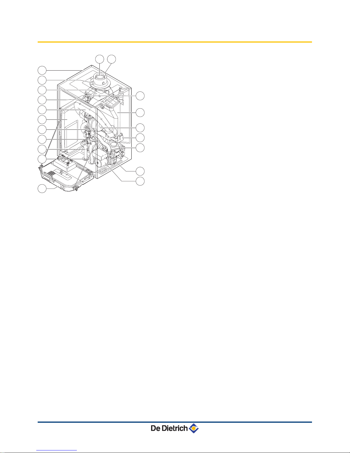
3.2 Main parts
1
Flue gas discharge pipe
2
Casing/air box
3
Flue gas measuring point
4
Mixer pipe
5
Heating flow hose
6
Air intake silencer
7
Box for the control PCBs
8
Combined venturi and gas valve unit
9
Flow end hydroblock
10
Safety valve outlet pipe
11
Siphon
12
Control panel
13
Shunt pump
14
Return end hydroblock
15
3-way valve
16
Condensate receiver tank
17
Fan
18
Heat exchanger (Heating circuit)
19
Ignition/ionization electrode
20
Air intake
T001964-D
2
14
15
13
16
17
18
19
3
4
5
6
7
8
9
10
11
12
1 20
MCA 35 3. Description
15/06/12 - 300022163-001-01
10
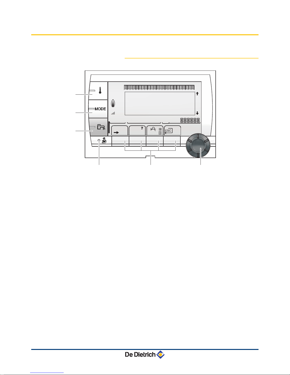
3.3 Control panel
3.3.1. Description of the keys
A
Temperature setting key (heating, DHW, swimming pool)
B
Operating mode selection key
C
DHW override key
D
Key to access the parameters reserved for the installer
E
Keys on which the function varies as and when selections
are made
F
Rotary setting button:
4 Turn the rotary button to scroll through the menus or
modify a value
4 Press the rotary button to access the selected menu
or confirm a value modification
A000866-A
bar
STD
t
0 2 4 6 8 10 12 14 16 18 22 2420
p
b
AUTO
x
c
r
j
M
g
m
A
B
C
D
E
F
(
'
3. Description MCA 35
11
15/06/12 - 300022163-001-01
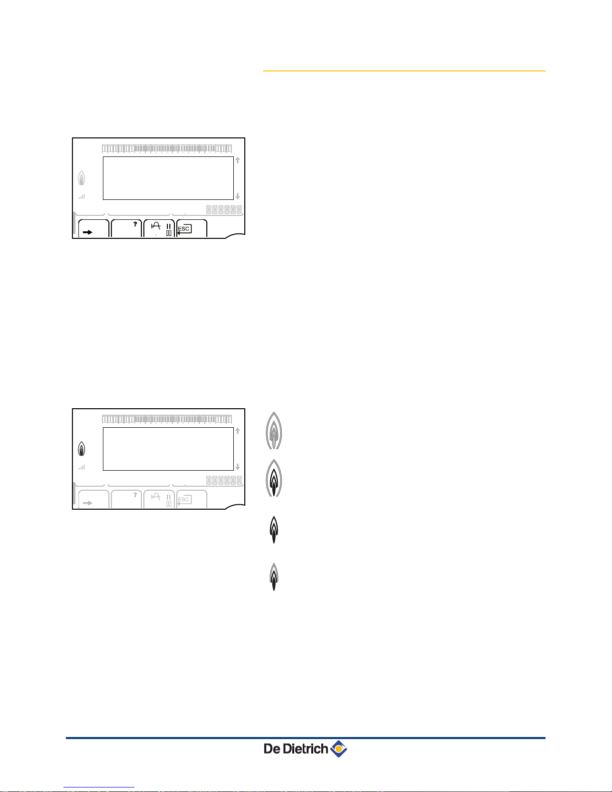
3.3.2. Description of the display
n
Key functions
>
Access to the various menus
(
Used to scroll through the menus
'
Used to scroll through the parameters
?
The symbol is displayed when help is available
f
Used to display the curve of the parameter selected
STD
Reset of the time programmes
b
Selection of comfort mode or selection of the days to be
programmed
v
Selection of reduced mode or deselection of the days to
be programmed
j
Back to the previous level
ESC
Back to the previous level without saving the
modifications made
t
Manual reset
n
Flame output level
C002705-A
The whole symbol flashes: The burner starts up but the
flame is not yet present
C002704-A
Part of the symbol flashes: Output is increasing
C002703-A
Steady symbol: The required output has been reached
C002702-A
Part of the symbol flashes: Output is dropping
bar
r
STD
(
'
t
0 2 4 6 8 10 12 14 16 18 22 2420
C002696-A
p
b
AUTO
x
c
r
j
L
g
m
bar
STD
t
0 2 4 6 8 10 12 14 16 18 22 2420
C002701-B
p
b
AUTO
x
c
r
j
M
g
m
MCA 35 3. Description
15/06/12 - 300022163-001-01
12
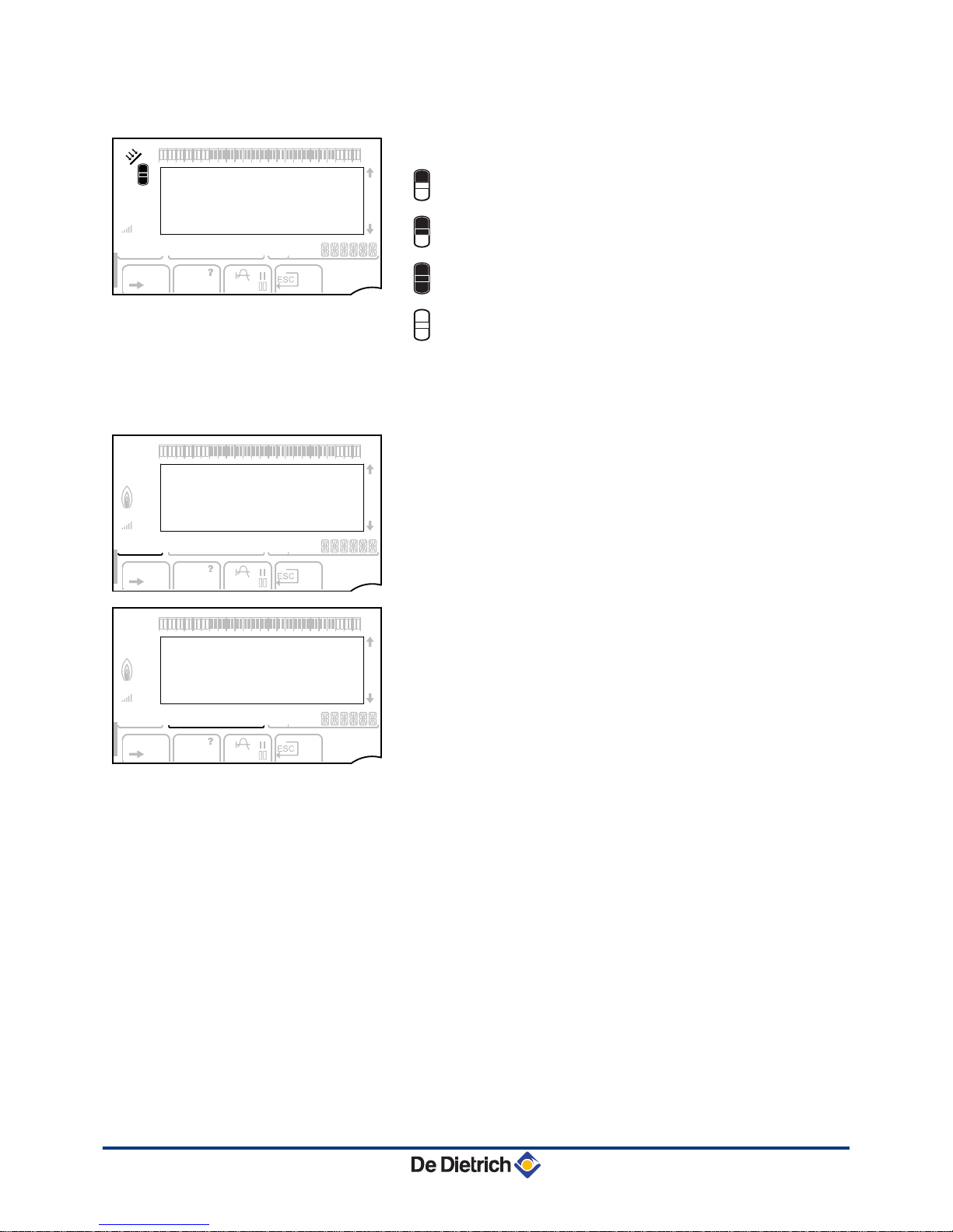
n
Solar (If connected)
u
The solar load pump is running
L000200-A
The top part of the tank is reheated to the tank set point
L000201-A
The entire tank is reheated to the tank set point
L000198-A
The entire tank is reheated to the solar tank set point
L000199-A
The tank is not loaded - Presence of the solar control
system
n
Operating modes
p
Summer mode: The heating is off. Domestic hot water
continues to be produced
b
WINTER mode: Heating and domestic hot water working
AUTO
Operation in automatic mode according to the timer
programme
x
Comfort mode: The symbol is displayed when a DAY
override (comfort) is activated
4 Flashing symbol: Temporary override
4 Steady symbol: Permanent override
m
Reduced mode: The symbol is displayed when a NIGHT
override (reduced) is activated
4 Flashing symbol: Temporary override
4 Steady symbol: Permanent override
g
Holiday mode: The symbol is displayed when a HOLIDAY
override (antifreeze) is activated
4 Flashing symbol: Holiday mode programmed
4 Steady symbol: Holiday mode active
m
Manual mode
bar
STD
t
0 2 4 6 8 10 12 14 16 18 22 2420
L000197-A
p
b
AUTO
x
c
r
j
M
g
m
bar
STD
t
0 2 4 6 8 10 12 14 16 18 22 2420
C002697-B
p
b
AUTO
x
c
r
j
M
g
m
bar
STD
t
0 2 4 6 8 10 12 14 16 18 22 2420
C002698-B
p
b
AUTO
x
c
r
j
M
g
m
3. Description MCA 35
13
15/06/12 - 300022163-001-01
 Loading...