

DeDietrich Innovens MCA 25/28 BIC, Innovens MCA 35 Installation And Service Manual
Innovens
Wall-hung gas condensing boilers
MCA 25/28 BIC
EN
Installation and
Service Manual
300022159-001-01

EG declaration of conformity
R000300-A
EG - VERKLARING VAN OVEREENSTEMMING
EC - DECLARATION OF CONFORMITY
EG - KONFORMITÄTSERKLÄRUNG
DÉCLARATION DE CONFORMITÉ CE
Fabrikant/Manufacturer/Hersteller/Fabricant : Remeha B.V.
Adres/Address /Adresse : Kanaal Zuid 110
Stad,Land/City,Country/Land,Ort/Ville, pays : Postbus 32, NL-7300 AA Apeldoorn
verklaart hiermede dat de toestel(len) : MCA ../.. (MI) (BIC)
this is to declare that the following product(s) :
erklärt hiermit das die Produk(te) :
déclare ici que les produit(s) suivant(s) :
op de markt gebracht door : De Dietrich Thermique
distributor : 57, rue de la Gare, F-67580
Vertreiber :
Commercialisé (s) par :
voldoet/voldoen aan de bepalingen van de onderstaande EEG-richtlijnen:
is/are in conformity with the following EEC-directives:
den Bestimmungen der nachfolgenden EG-Richtlinien entspricht/entsprechen:
répond/répondent aux directives CEE suivantes:
EEG-Richtlijn: 2009/142/EC toegepaste normen:
EEC-Directive: 2009/142/EC tested and examined tothe following norms:
EG-Richtlinie: 2009/142/EG verwendete Normen, normes appliquées:
CEE-Directive: 2009/142/CE EN 297
(1994*)
, 483
(1999*)
, 677
(1998*)
92/42/EEG
92/42/EEC
92/42/EWG
92/42/CEE
2006/95/EEG
EN 50165
(1997*),
EN 60335-1
(1994*)
2006/95/EEC EN 60335-2-102
(2004*)
08
2006/95/EWG
2006/95/CEE
2004/108/EEG
EN 50165
(1997*)
2004/108/EEC EN 55014-2
(1997*),
EN 55014-1
(2000*),
2004/108/EWG EN 61000-3-2
(2000*)
, 61000-3-3
(1995*)
2004/108/CEE
97/23/EEG (art. 3, lid 3)
97/23/EEC (article 3, sub 3)
97/23/EWG (Art. 3, Abzats 3)
97/23/CEE (art.3 section 3)
*) inclusief (eventuele) aanvulling, including (if any) completion
einschließlich (falls vorhanden) Vervollständigung, y compris (le cas échéant) complément
Apeldoorn
, february 2010
W.F. Tijhuis
Approval manager
703/2012/02/232
The device complies with the standard type described in the EG
declaration of conformity. It was manufactured and commissioned in
accordance with European directives.
The original of the declaration of compliance is available from the
manufacturer.

Contents
1 Introduction ................................................................................................6
1.1 Symbols used .......................................................6
1.2 Abbreviations ........................................................6
1.3 General ..................................................................7
1.3.1 Manufacturer's liability .............................................7
1.3.2 Installer's liability .....................................................7
1.4 Homologations ......................................................7
1.4.1 Certifications ...........................................................7
1.4.2 Equipment categories .............................................8
1.4.3 Additional Directives ................................................8
1.4.4 Factory test .............................................................8
2 Safety instructions and recommendations ..............................................9
2.1 Safety instructions ...............................................9
2.2 Recommendations ................................................9
3 Technical description ..............................................................................11
3.1 General description ............................................11
3.2 Main parts ............................................................11
3.3 Operating principle .............................................12
3.3.1 Skeleton Diagrams ................................................12
3.3.2 Shunt pump ...........................................................12
3.3.3 Water flow rate ......................................................13
3.4 Technical specifications ....................................13
3.4.1 Sensor characteristics ...........................................14
4 Installation ................................................................................................15
4.1 Regulations governing installation ...................15
4.2 Package list .........................................................15
4.2.1 Standard delivery ..................................................15
4.2.2 Accessories ...........................................................15
15/06/12 - 300022159-001-01
4.3 Choice of the location ........................................16
4.3.1 Data plate ..............................................................16
4.3.2 Location of the boiler .............................................16
4.3.3 Ventilation .............................................................17
4.3.4 Main dimensions ...................................................18
1

Contents
4.4 Installing the mounting frame ...........................19
4.5 Positioning the boiler .........................................19
4.6 Hydraulic connections .......................................20
4.6.1 Flushing the system ..............................................20
4.6.2 Connection of the heating circuit ...........................21
4.6.3 Connection of the water circuit for domestic
use ........................................................................21
4.6.4 Connecting the expansion vessel .........................22
4.6.5 Connecting the condensate discharge pipe ..........23
4.7 Gas connection ...................................................23
4.8 Flue gas system connections ............................24
4.8.1 Classification .........................................................24
4.8.2 Lengths of the air/flue gas pipes ...........................25
4.8.3 Additional Directives ..............................................26
4.9 Installing the outside sensor .............................27
4.9.1 Choice of the location ............................................27
4.9.2 Connecting the outside sensor ..............................27
4.10 Electrical connections ........................................28
4.10.1 Control unit ............................................................28
4.10.2 Recommendations ................................................29
4.10.3 Position of the PCBs .............................................30
4.10.4 Accessing the connection terminal blocks ............31
4.10.5 Connecting a direct heating circuit ........................33
4.10.6 Connecting two heating circuits ............................34
4.10.7 Hot water storage tank connection (Type
PS) ........................................................................35
4.10.8 Pool connection .....................................................37
4.10.9 Connecting the options .........................................38
4.11 Electrical diagram ...............................................40
4.12 Filling the system ...............................................41
4.12.1 Water treatment ....................................................41
4.12.2 Filling the siphon ...................................................42
4.12.3 Filling the system ..................................................42
5 Commissioning ........................................................................................44
5.1 Control panel .......................................................44
5.1.1 Description of the keys ..........................................44
5.1.2 Description of the display ......................................45
5.1.3 Access to the various browsing levels ..................48
5.1.4 Browsing in the menus ..........................................49
15/06/12 - 300022159-001-01
5.2 Check points before commissioning ................50
5.2.1 Preparing the boiler for commissioning .................50
5.2.2 Gas circuit .............................................................51
5.2.3 Hydraulic circuit .....................................................51
5.2.4 Electrical connections ...........................................51
2

5.3 Commissioning the boiler ..................................51
5.4 Gas settings ........................................................52
5.4.1 Adapting to another gas type ................................52
5.4.2 Setting the air/gas ratio (Full load) ........................53
5.4.3 Setting the air/gas ratio (Part load) ......................54
5.4.4 Basic setting for the gas/air ratio ...........................56
5.5 Checks and adjustments after
commissioning ...................................................56
5.5.1 Displaying the parameters in extended
mode .....................................................................56
5.5.2 Setting the parameters specific to the
installation .............................................................57
5.5.3 Naming the circuits and generators ......................61
5.5.4 Setting the heating curve ......................................62
5.5.5 Finalizing work ......................................................64
5.6 Reading out measured values ...........................65
5.7 Changing the settings ........................................66
5.7.1 Language selection ...............................................66
5.7.2 Calibrating the sensors .........................................66
5.7.3 Professional settings .............................................68
5.7.4 Configuring the network ........................................75
5.7.5 Return to the factory settings ................................78
6 Switching off the boiler ............................................................................80
6.1 Installation shutdown .........................................80
6.2 Frost protection ..................................................80
7 Checking and maintenance .....................................................................81
7.1 General instructions ...........................................81
7.2 Chimney sweep instructions .............................81
7.3 Customising maintenance .................................82
7.3.1 Maintenance message ..........................................82
7.3.2 Contact details of the professional for After Sales
Support ..................................................................83
7.4 Standard inspection and maintenance
operations ...........................................................83
7.4.1 Checking the hydraulic pressure ...........................84
7.4.2 Checking the expansion vessel .............................84
7.4.3 Checking the ionization current .............................84
7.4.4 Checking the transfer capacity ..............................84
7.4.5 Checking the tightness of the flue gas evacuation and
air inlet connections ..............................................84
7.4.6 Checking combustion ............................................85
7.4.7 Checking the automatic air vent ............................86
7.4.8 Checking the safety valve .....................................86
7.4.9 Checking the siphon ..............................................86
15/06/12 - 300022159-001-01
3

Contents
7.4.10 Checking the burner and cleaning the heat
exchanger .............................................................87
7.5 Specific maintenance operations ......................88
7.5.1 Replacing the ionization/ignition electrode ............88
7.5.2 Cleaning the plate exchanger ...............................89
7.5.3 Replacing the boiler tanks .....................................90
7.5.4 Replacing the 3-way valve ....................................91
7.5.5 Replacing the non-return valve .............................92
7.5.6 Assembling the boiler ............................................93
8 Troubleshooting .......................................................................................94
8.1 Anti-hunting ........................................................94
8.2 Messages (Code type Bxx or Mxx) ....................94
8.3 Message history ..................................................97
8.4 Faults (Code type Lxx or Dxx) ...........................97
8.4.1 Deletion of sensors from the memory in the
PCB .....................................................................106
8.5 Failure history ...................................................106
8.6 Parameter and input/output check (mode
tests) ..................................................................107
8.6.1 Control system sequence ....................................110
9 Spare parts ..............................................................................................111
9.1 General ..............................................................111
9.2 Spare parts ........................................................111
9.2.1 Casing .................................................................112
9.2.2 Heat exchanger and burner ................................113
9.2.3 Fan ......................................................................114
9.2.4 Control panel .......................................................115
9.2.5 Connecting pipes ................................................116
9.2.6 Spare parts list ....................................................117
15/06/12 - 300022159-001-01
4

15/06/12 - 300022159-001-01
5
1. Introduction
1 Introduction
1.1 Symbols used
MCA 25/28 BIC
In these instructions, various danger levels are employed to draw the
user's attention to particular information. In so doing, we wish to
safeguard the user's safety, obviate hazards and guarantee correct
operation of the appliance.
DANGER
Risk of a dangerous situation causing serious physical
injury.
WARNING
Risk of a dangerous situation causing slight physical
injury.
1.2 Abbreviations
CAUTION
Risk of material damage.
Signals important information.
¼ Signals a referral to other instructions or other pages in the
instructions.
4 3CE: Collective conduit for sealed boiler
4 DHW: Domestic hot water
4 Hi: Lower heating value LHV (Nett)
4 Hs: Higher heating value HHV (Gross)
4 PPS: Polypropylene hardly inflammable
4 PCU: Primary Control Unit - PCB for managing burner operation
4 PSU: Parameter Storage Unit - Parameter storage for PCBs
PCU and SU
4 SCU: Secondary Control Unit - control panel PCB
4 SU: Safety Unit - Safety PCB
4 3WV: 3-way valve
6
15/06/12 - 300022159-001-01

MCA 25/28 BIC 1. Introduction
1.3 General
1.3.1. Manufacturer's liability
Our products are manufactured in compliance with the requirements
of the various applicable European Directives. They are therefore
delivered with [ marking and all relevant documentation.
In the interest of customers, we are continuously endeavouring to
make improvements in product quality. All the specifications stated in
this document are therefore subject to change without notice.
Our liability as the manufacturer may not be invoked in the following
cases:
4 Failure to abide by the instructions on using the appliance.
4 Faulty or insufficient maintenance of the appliance.
4 Failure to abide by the instructions on installing the appliance.
1.4 Homologations
1.3.2. Installer's liability
The installer is responsible for the installation and inital start up of the
appliance. The installer must respect the following instructions:
4 Read and follow the instructions given in the manuals provided
with the appliance.
4 Carry out installation in compliance with the prevailing legislation
and standards.
4 Perform the initial start up and carry out any checks necessary.
4 Explain the installation to the user.
4 If a maintenance is necessary, warn the user of the obligation to
check the appliance and maintain it in good working order.
4 Give all the instruction manuals to the user.
1.4.1. Certifications
15/06/12 - 300022159-001-01
CE identification no
NOx classification
Type of connection
(1) IP20
PIN 0063BT3444
5 (EN 297 pr A3, EN 656)
83(x)
(1)
, C
Chimney: B23
Flue gas outlet: C
C
, C
63(x)
, B
13(x)
93(x)
23P
(1)
, C
, B
33(x)
33
, C
43(x)
, C53 ,
7
1. Introduction MCA 25/28 BIC
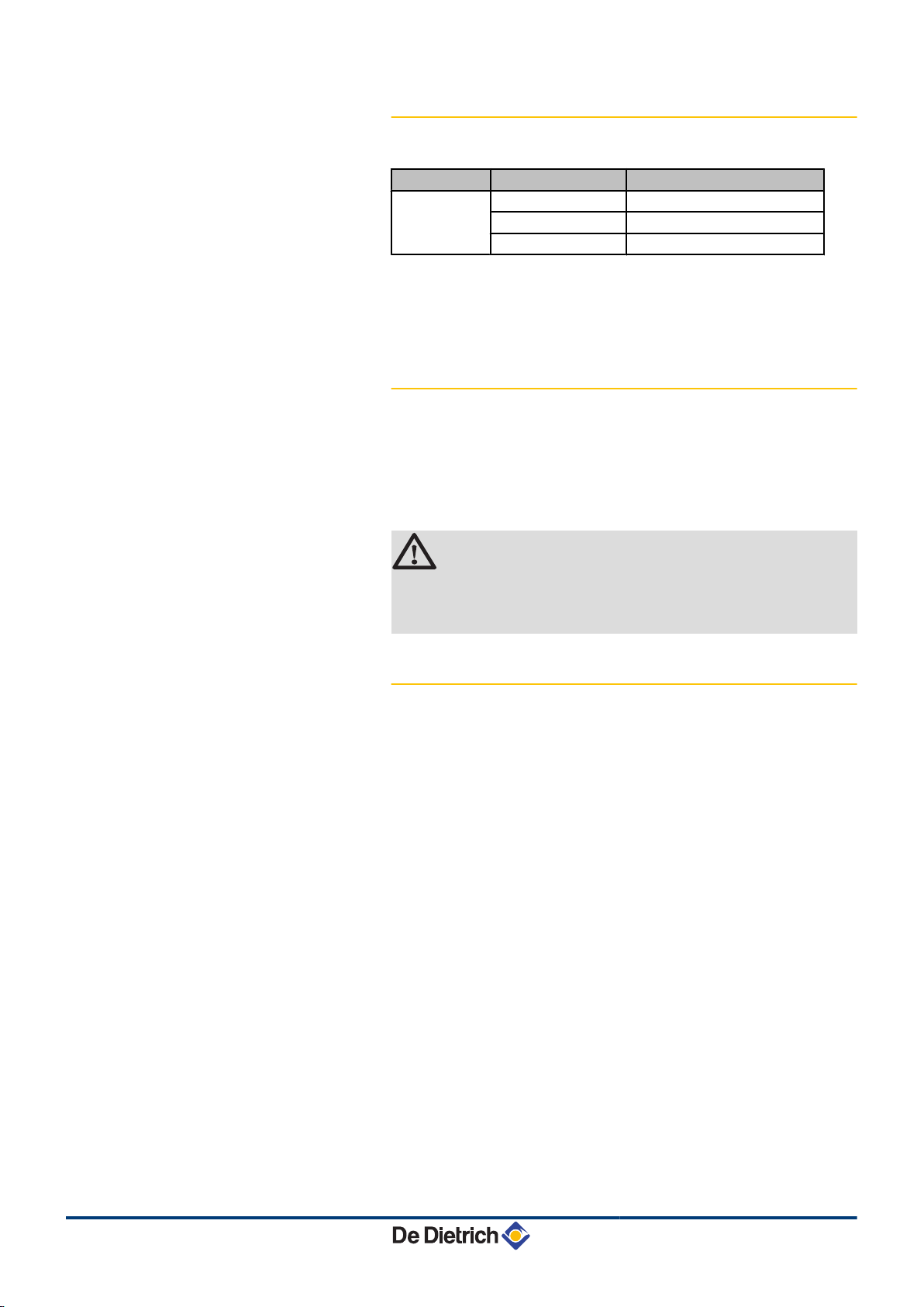
1.4.2. Equipment categories
Gas category Gas type Connection pressure (mbar)
II
2ESi3P
Natural gas H (G20) 20
Natural gas L (G25) 25
Propane (G31) 37
The boiler is preset in the factory to operate on natural gas H (G20).
¼ For operation on another type of gas, see chapter: "Adapting
to another gas type", page 52.
1.4.3. Additional Directives
Apart from the legal provisions and Directives, the additional
Directives described in these instructions must also be observed.
For all provisions and Directives referred to in these instructions, it is
agreed that all addenda or subsequent provisions will apply at the
time of installation.
WARNING
Installation of the appliance must be done by a qualified
engineer in accordance with prevailing local and national
regulations.
1.4.4. Factory test
Before leaving the factory, each boiler is set for optimum performance
and tested to check the following items:
4 Electrical safety
4 Adjustment (CO2)
4 Water tightness
4 Gas tightness
4 Parameter settings
8
15/06/12 - 300022159-001-01
MCA 25/28 BIC
2 Safety instructions and
recommendations
2.1 Safety instructions
DANGER
If you smell gas:
1. Do not use a naked flame, do not smoke, do not
operate electrical contacts or switches ( doorbell,
light, motor, lift, etc..).
2. Shut off the gas supply.
3. Open the windows.
4. Trace possible leaks and seal them immediately.
5. If the gas leak is before the gas meter, contact the
gas supplier.
2. Safety instructions and recommendations
2.2 Recommendations
DANGER
If you smell flue gases:
1. Switch the appliance off.
2. Open the windows.
3. Trace possible leaks and seal them immediately.
WARNING
4 Installation and maintenance of the boiler must be
carried out by a qualified professional in compliance
with prevailing local and national regulations.
4 When working on the boiler, always disconnect the
boiler from the mains and close the main gas inlet
valve.
4 After maintenance or repair work, check all
installations to ensure that there are no leaks.
CAUTION
15/06/12 - 300022159-001-01
The boiler must be installed in a frost-free environment.
Keep this document close to the place where the boiler is
installed.
Casing components
9

2. Safety instructions and recommendations MCA 25/28 BIC
Only remove the casing for maintenance and repair operations. Put
the casing back in place after maintenance and repair operations.
Instructions stickers
The instructions and warnings affixed to the appliance must never be
removed or covered and must remain legible during the entire lifespan
of the appliance. Immediately replace damaged or illegible
instructions and warning stickers.
Modifications
Modifications may only be made to the boiler after the written
permission of De Dietrich Thermique to do so.
10
15/06/12 - 300022159-001-01
T001961-D
2
19
18
17
16
15
20
21
22
23
24
25
26
3
4
5
6
7
8
9
10
11
12
1
14 13
27
MCA 25/28 BIC 3. Technical description
3 Technical description
3.1 General description
Wall-hung gas condensing boilers
4 High efficiency heating.
4 Low pollutant emissions.
4 Top of the range electronic DIEMATIC iSystem control panel.
4 Installation and connection facilitated by the mounting frame
delivered with the appliance.
4 Flue gas discharge via a forced flue, chimney, bi-flow or 3CE type
connection.
4 Heating and domestic hot water production with integrated DHW
tank.
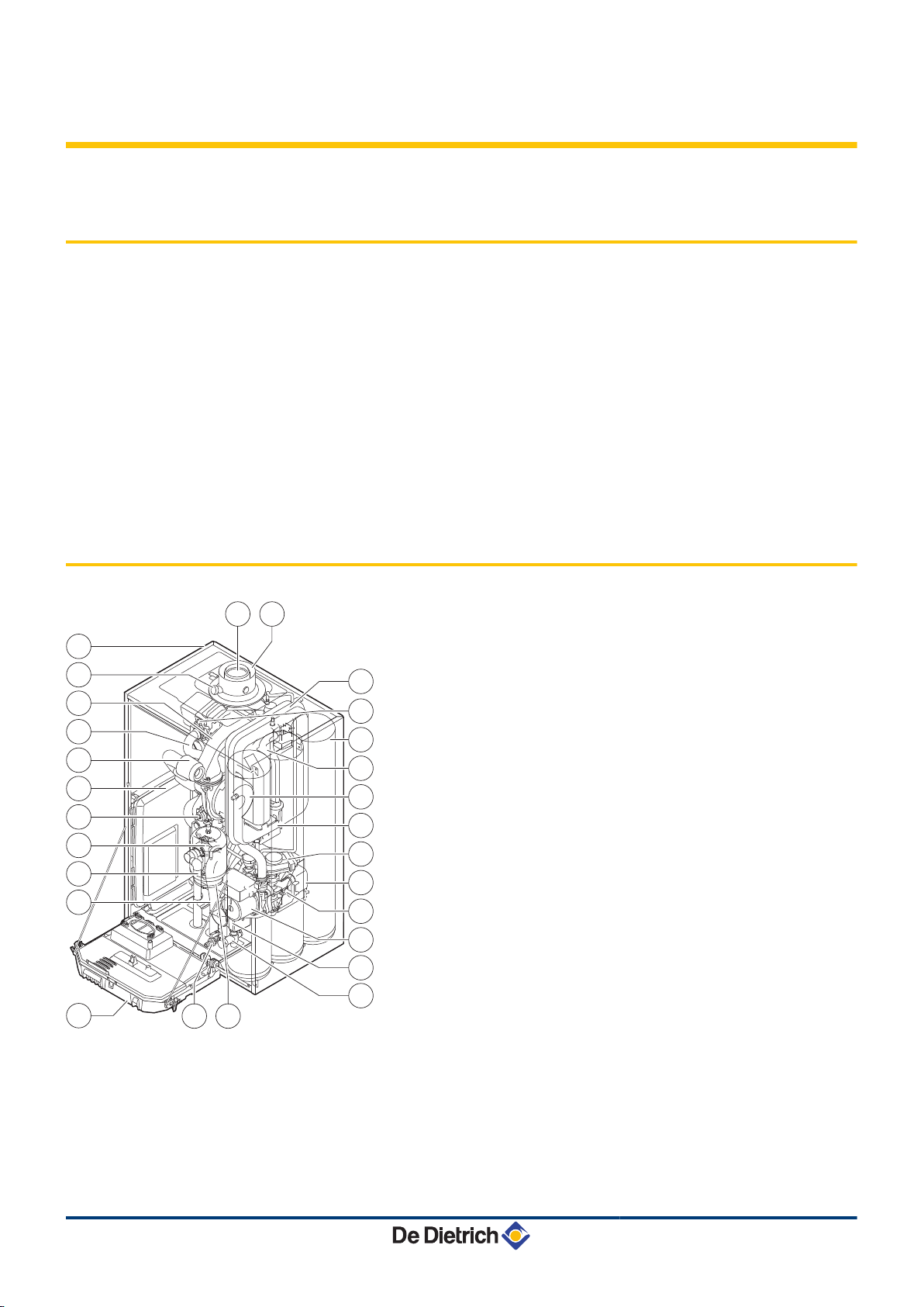
3.2 Main parts
1
2
3
4
5
6
7
8
9
10
11
12
13
14
15
16
17
18
19
20
21
22
Flue gas discharge pipe
Casing/air box
Flue gas measuring point
Mixer pipe
Heating flow hose
Air intake silencer
Box for the control PCBs
Combined venturi and gas valve unit
Flow end hydroblock
Safety valve outlet pipe
Siphon
Control panel
Tank drainage valve
Expansion vessel (DHW circuit)
Tank hydroblock
Shunt pump (DHW circuit)
Shunt pump (Heating circuit)
Return end hydroblock
Plate heat exchanger (DHW circuit)
3-way valve
Condensate receiver tank
Fan
15/06/12 - 300022159-001-01
11
T001960-A
1
2
3
11
10
12
13
8
9
4 5 6 7
T002537-B
0 200 400 600 800 1000 1200
Q (l/h)
10 kW
15 kW
20 kW
25 kW
615
545
435
295
437 623 830 1037
0
100
200
300
400
500
700
H (mbar)
600
3. Technical description
MCA 25/28 BIC
3.3 Operating principle
23
24
25
26
27
Heat exchanger (Heating circuit)
Calorifier tank
Ignition/ionization electrode
Expansion vessel (Heating circuit)
Air intake
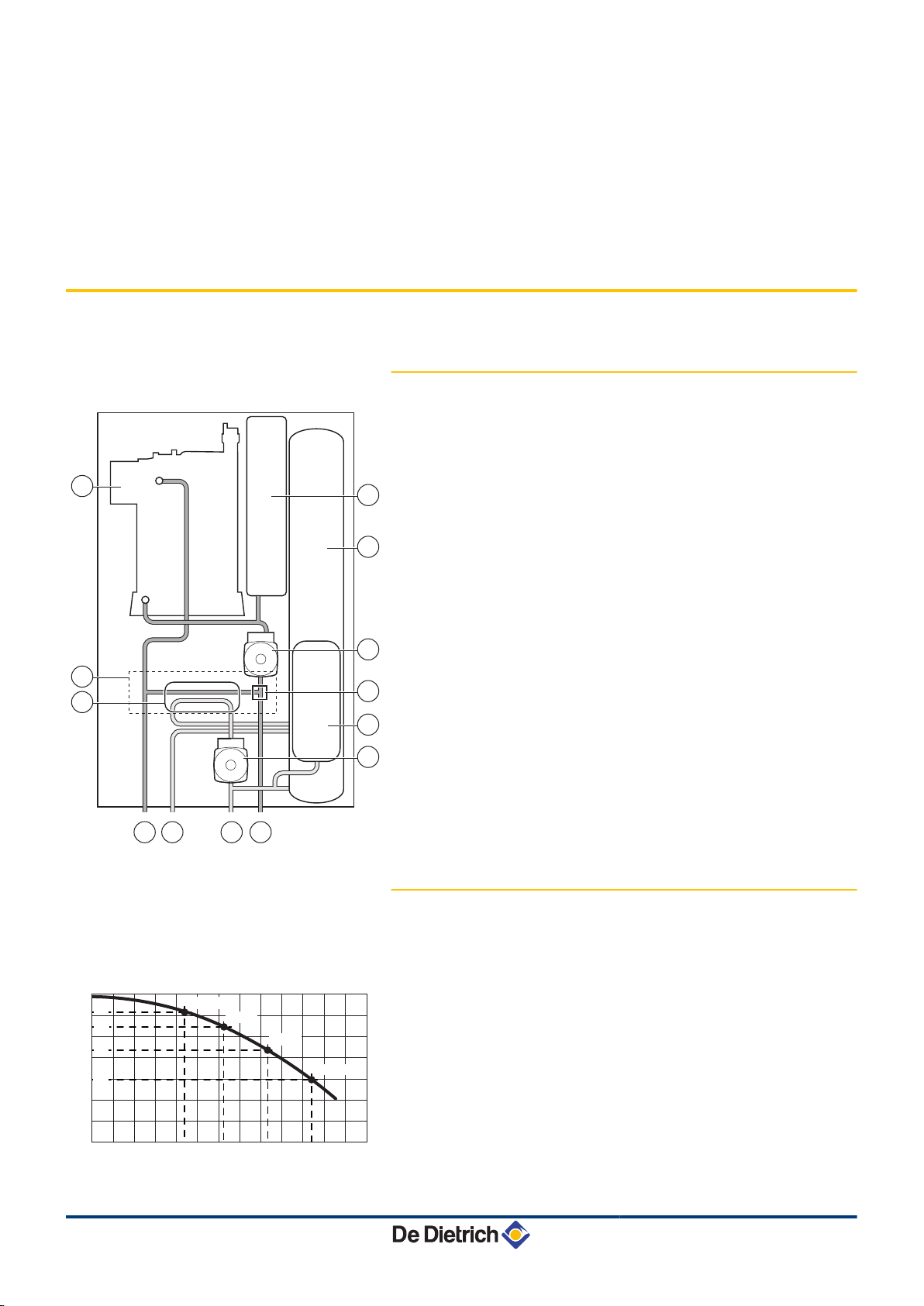
3.3.1. Skeleton Diagrams
1
2
3
4
5
Heat exchanger (Heating circuit)
Hydroblocks
Plate heat exchanger (DHW circuit)
Heating flow
Domestic hot water outlet
6
7
8
9
10
11
12
13
Domestic cold water inlet
Heating return
Shunt pump (DHW circuit)
Expansion vessel (DHW circuit)
3-way valve
Shunt pump (Heating circuit)
Calorifier tank
Expansion vessel (Heating circuit)
3.3.2. Shunt pump
The boiler is equipped with a circulating pump. This energy-efficient,
modulating circulating pump is controlled by the control unit based on
ΔT. The graph shows the manometric height at various outputs.
H
Manometric height central heating circuit
12
Q
Water flow
The parameters MIN.PUMP SPEED and MAX.PUMP SPEED are
used to modify the pump settings. If flow noise can be heard in the
system, it is possible to reduce the maximum pump speed with the
parameter MAX.PUMP SPEED (First of all, vent the heating
system). If circulation in the radiators is too low or the radiators do not
fully heat up, increase the minimum pump speed with the parameter
MIN.PUMP SPEED.
15/06/12 - 300022159-001-01
MCA 25/28 BIC 3. Technical description
¼ See chapter: "Professional settings", page 68.
3.3.3. Water flow rate
The boiler's modulating control system limits the maximum difference
in temperature between the heating flow and return and the maximum
speed at which the flow temperature increases. In this way, the boiler
does not require a minimum water flow rate.
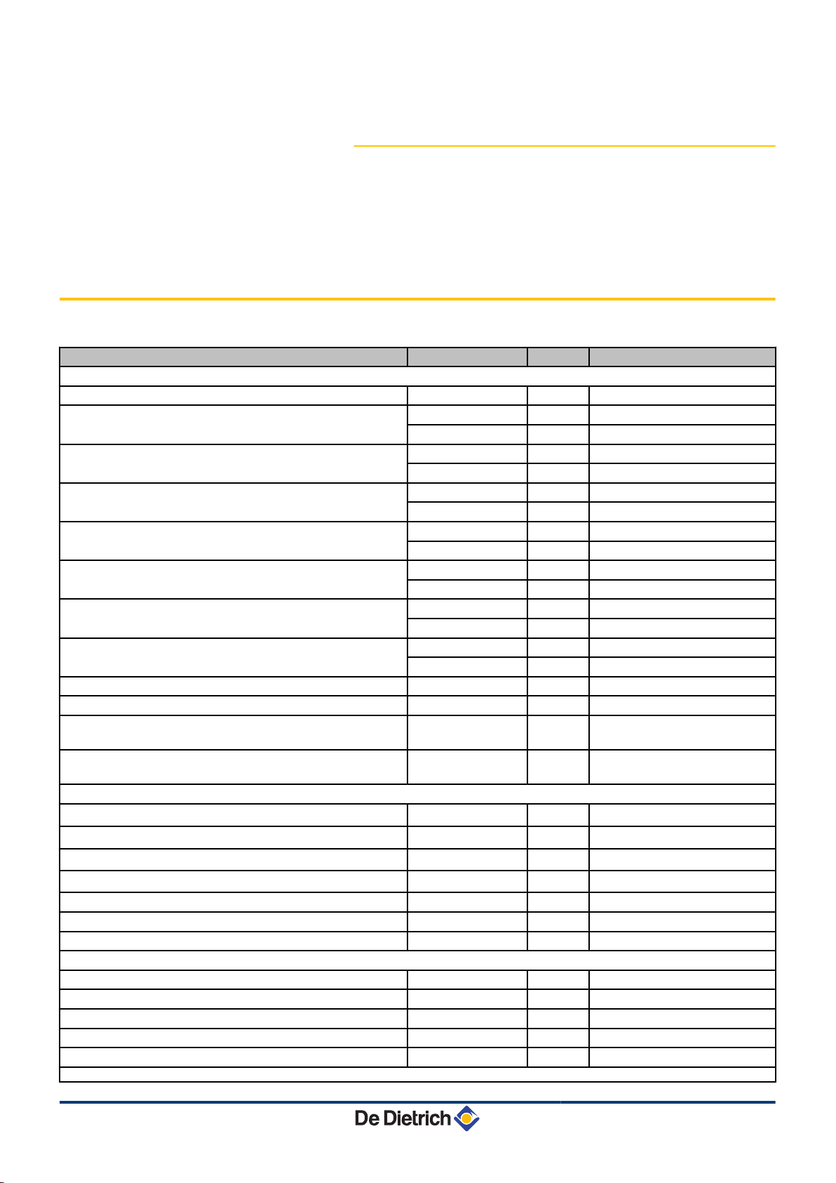
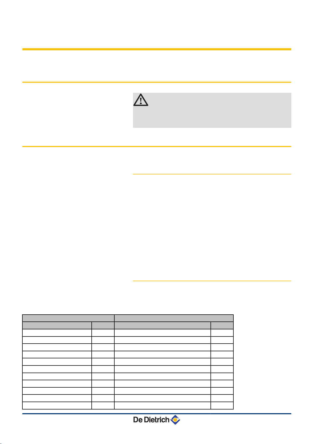
3.4 Technical specifications
Boiler type
General
Flow rate setting Adjustable
Nominal output (Pn)
Heating System (80/60 °C)
Nominal output (Pn)
Heating System (50/30 °C)
Nominal output (Pn)
DHW System
Nominal input (Qn)
Heating System (Hi)
Nominal input(Qn)
Heating System (Hs)
Nominal input (Qnw)
DHW System (Hi)
Nominal input (Qnw)
DHW System (Hs)
Heating efficiency under full load (Hi) (80/60 °C) - % 96,3
Heating efficiency under full load (Hi) (50/30 °C) - % 102,0
Heating efficiency under partial load (Hi) (Return temperature
60°C)
Heating efficiency under partial load (EN 92/42) (Return
temperature 30°C)
Data on the gases and combustion gases
Gas consumption - Natural gas H (G20) minimum-maximum
Gas consumption - Natural gas L (G25) minimum-maximum
Gas consumption - Propane G31 minimum-maximum
NOx-Emission per year (n =1)
Mass flue gas flow rate minimum-maximum kg/h 8,9 - 49,3
Flue gas temperature minimum-maximum °C 30 - 85
Maximum counter pressure
Characteristics of the heating circuit
Water content
Water operating pressure minimum kPa (bar) 80 (0,8)
Water operating pressure (PMS) maximum kPa (bar) 300 (3,0)
Water temperature maximum °C 110
Operating temperature maximum °C 90
(1) Front panel removed
minimum-maximum kW 5,0 - 24,1
Factory setting kW 19,4
minimum-maximum kW 5,6 - 25,5
Factory setting kW 20,5
minimum-maximum kW 5,0 - 29,9
Factory setting kW 29,9
minimum-maximum kW 5,2 - 25,0
Factory setting kW 20,1
minimum-maximum kW 5,8 - 27,8
Factory setting kW 22,3
minimum-maximum kW 5,2 - 29,3
Factory setting kW 29,3
minimum-maximum kW 5,8 - 32,6
Factory setting kW 32,6
- % 96,1
- % 108,0
m3/h
m3/h
m3/h
mg/kWh 38
Pa 130
l 1,8
MCA 25/28 BIC
Modulating, Start/Stop, 0 - 10 V
0,55 - 3,10
0,64 - 3,61
0,21 - 1,20
15/06/12 - 300022159-001-01
13
3. Technical description MCA 25/28 BIC
Boiler type
Manometric height central heating circuit (∆T = 20K)
Characteristics of the domestic hot water circuit
Specific hot water flow D (60 °C)
Specific hot water flow D (30 °C)
Domestic water resistance
Water content
Operating pressure (Pmw) maximum kPa (bar) 800 (8,0)
Electrical characteristics
Power supply voltage
Power consumption - Full load
Power consumption - Part load maximum W 21
Power consumption - Standby maximum W 4
Electrical protection index
Other characteristics
Weight (empty)
Acoustic level at 1 metre
(1) Front panel removed
maximum W 162
Factory setting W 72
mbar 295
l/min 7,5
l/min 20,0
mbar 20
l 40,5
VAC 230
Total kg 70
Mounting
(1)
kg 61
dB(A) 44
MCA 25/28 BIC
IPX4D
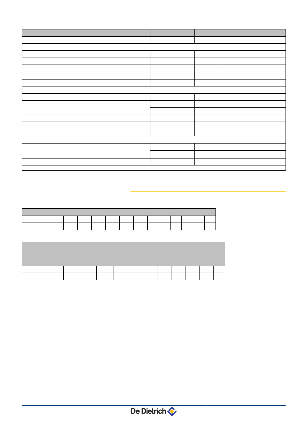
3.4.1. Sensor characteristics
Outside sensor
Temperature in °C -20 -16 -12 -8 -4 0 4 8 12 16 20 24
Resistance in Ω 2392 2088 1811 1562 1342 1149 984 842 720 616 528 454
Outlet sensor circuit B+C
Domestic hot water sensor
System sensor
Flow sensor - Return sensor NTC
Temperature in °C 0 10 20 25 30 40 50 60 70 80 90
Resistance in Ω 32014 19691 12474 10000 8080 5372 3661 2535 1794 1290 941
14
15/06/12 - 300022159-001-01
MCA 25/28 BIC 4. Installation
4 Installation
4.1 Regulations governing installation
WARNING
Installation of the appliance must be done by a qualified
engineer in accordance with prevailing local and national
regulations.
4.2 Package list
4.2.1. Standard delivery
The delivery includes:
4 The boiler, fitted with a connection cable
4 Mounting frame
4 Mounting template
4 Connection kit
4 Run-off collector for siphon and safety valve
4 Outside sensor
4 Installation and Service Manual
4 User Guide
4.2.2. Accessories
Various options are available depending on the configuration of the
installation:
Boiler options
Description package Description package
Stand-off frame HR39 RX12 cable AD134
Pipework kit for stand-off frame HR40 TELCOM 2 voice remote monitoring module AD152
Pipe cover HR42 Flow sensor AD199
Flue gas thermostat HR43 DHW sensor AD212
adapter 80/125 HR38 Optional PCB for 3-way valve AD249
adapter 80-80 HR46 Hot water storage tank sensor AD250
Exchanger cleaning kit HR44 Outside radio-controlled temperature sensor AD251
Boiler body cleaning kit HR45 Boiler radio module AD252
Control system options
Radio remote control AD253
Interactive remote control AD254
Room sensor FM52
15/06/12 - 300022159-001-01
15
T001539-B
T001898-C
600
min.1000
500
min.
250
min.
250
900
4. Installation MCA 25/28 BIC
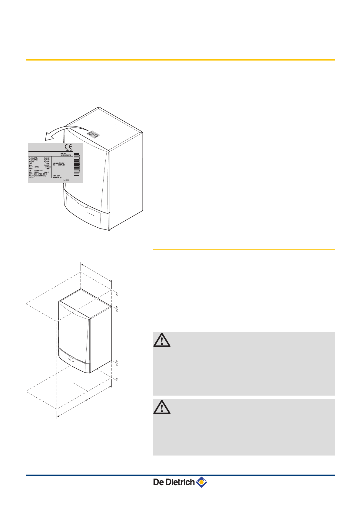
4.3 Choice of the location
4.3.1. Data plate
The data plate located on top of the boiler provides important
information on the appliance: serial number, model, gas category, etc.
4.3.2. Location of the boiler
4 Before mounting the boiler, decide on the ideal position for
mounting, bearing the Directives and the dimensions of the
appliance in mind.
4 When choosing the position for mounting the boiler, bear in mind
the authorised position of the combustion gas discharge outlets
and the air intake opening.
4 To ensure adequate accessibility to the appliance and facilitate
maintenance, leave enough space around the boiler.
WARNING
4 Fix the appliance to a solid wall capable of bearing
the weight of the appliance when full of water and fully
equipped.
4 It is forbidden to store inflammable products and
materials in the boiler room or close to the boiler,
even temporarily.
CAUTION
16
4 The boiler must be installed in a frost-free
environment.
4 A connection to the mains drainage system for the
discharge of condensate must be available close to
the boiler.
15/06/12 - 300022159-001-01
T001899-B
min. 700
min.600
50 (2)
min. 250
min. 250
100
min. (1)
MCA 25/28 BIC 4. Installation
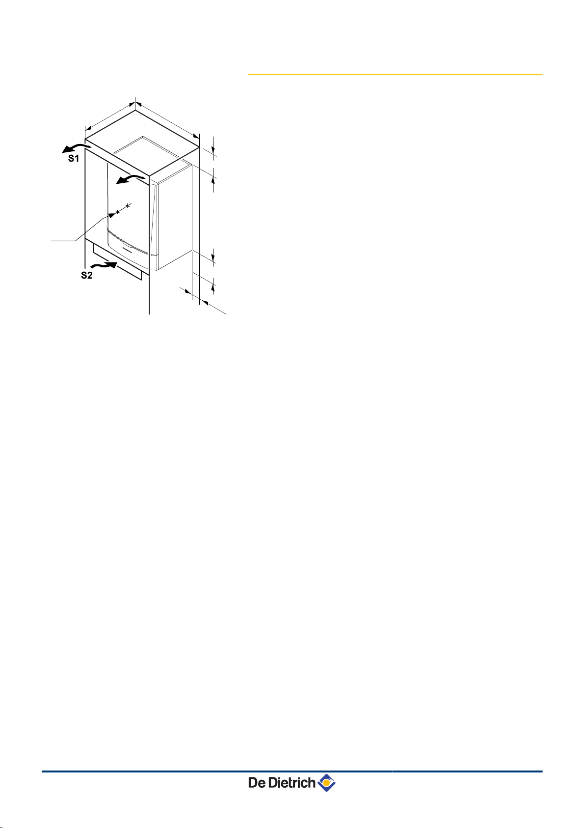
4.3.3. Ventilation
(1)
Distance between the front of the boiler and the internal
wall of the casing box.
(2)
Distance to allow on either side of the boiler.
If the boiler is installed in a closed casing, respect the minimum
dimensions given in the diagram opposite. Also allow openings to
obviate the following hazards:
4 Accumulation of gas
4 Heating of the box
Minimum cross section of the openings: S1 + S2 = 150 cm
2
15/06/12 - 300022159-001-01
17
T001962-A
217
345
415
282
349
416
481
900
600
498
375
140
140
150
257,5
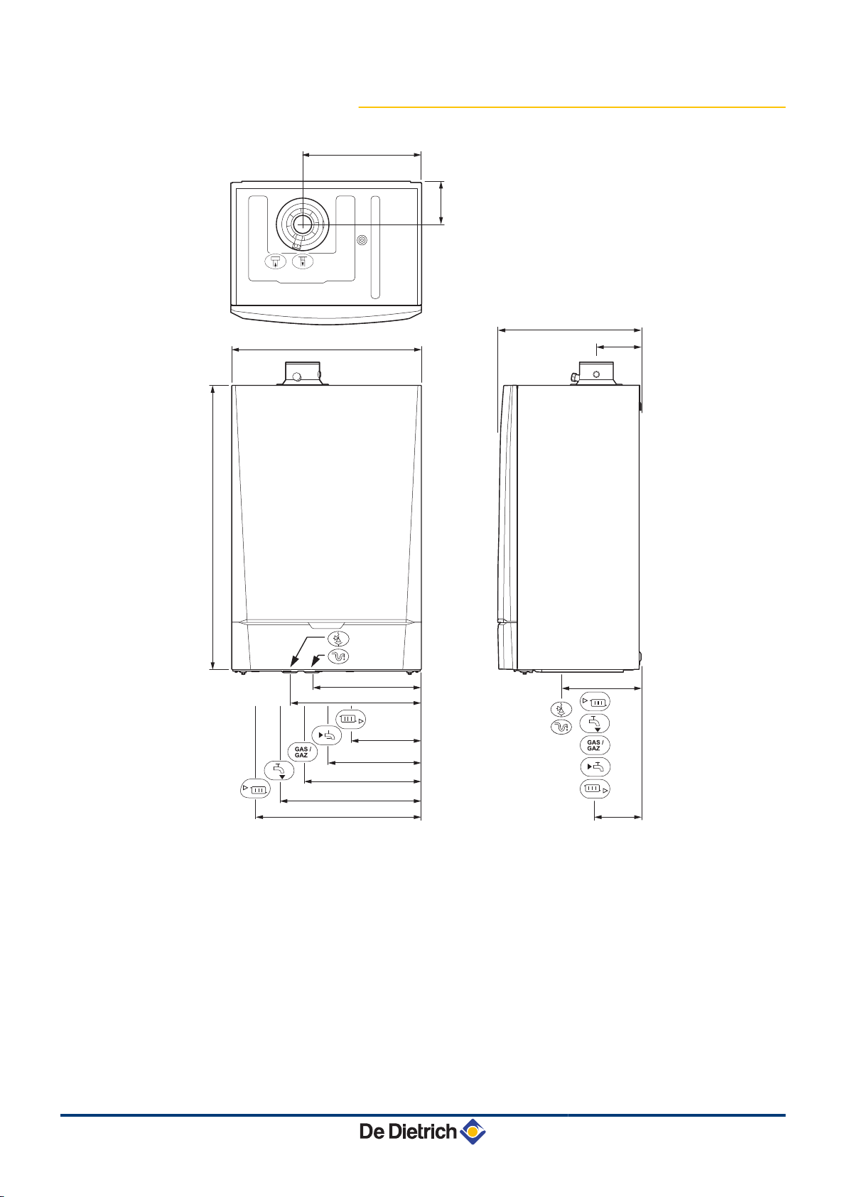
4. Installation MCA 25/28 BIC
4.3.4. Main dimensions
i
h
ê
j
z
x
Gas /
Gaz
Connection of the combustion gas exhaust pipe Ø 60 mm
Connection of the air intake pipe Ø 100 mm
Safety valve outlet pipe Ø 25 mm
Condensates discharge Ø 25 mm
Heating circuit return G¾"
Domestic cold water inlet G½"
Gas connection G½"
18
y
{
Domestic hot water outlet G½"
Heating circuit flow G¾"
15/06/12 - 300022159-001-01
T001869-A
1
2
3
4
T001870-A
MCA 25/28 BIC 4. Installation
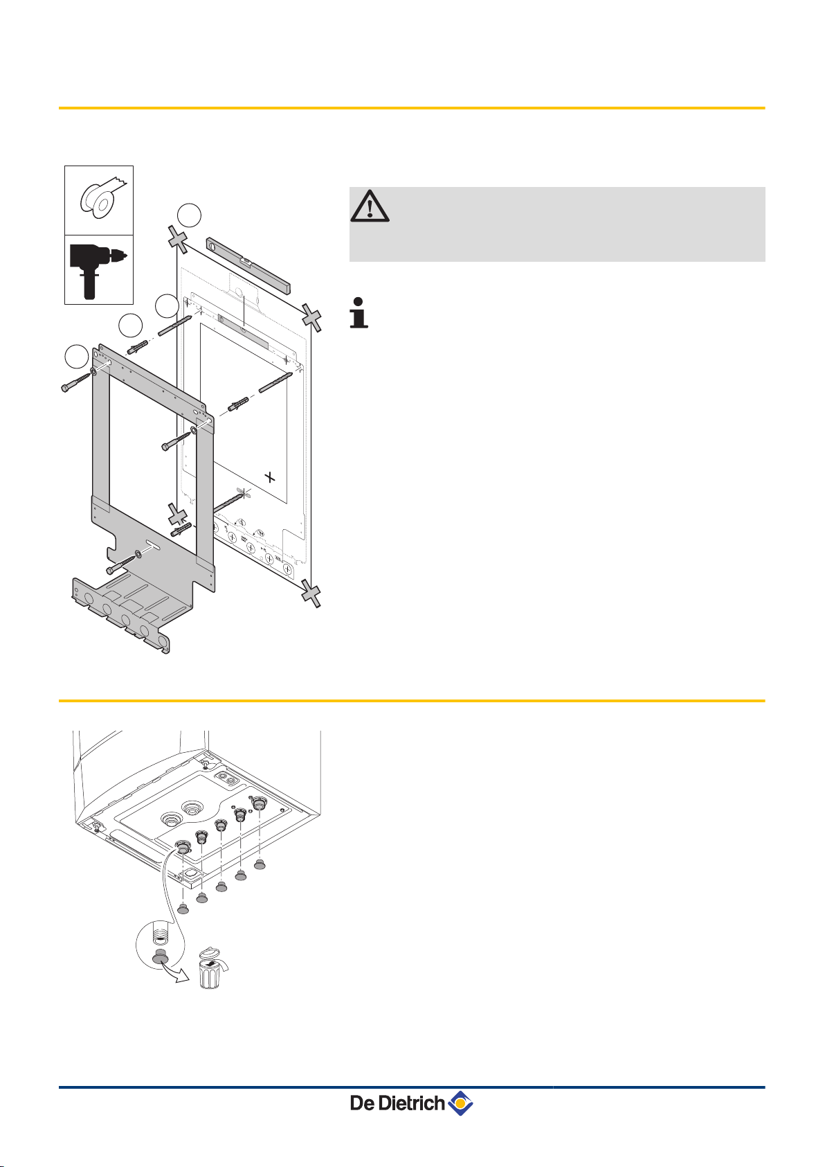
4.4 Installing the mounting frame
The boiler is delivered with a mounting template.
1. Position the mounting template to the wall with adhesive tape.
CAUTION
Using a spirit level, check that the mounting axis is
perfectly horizontal.
2. Drill 3 holes with a Ø of 10 mm.
Additional holes are provided in case one or other of the
standard locating holes prevents the correct location of the
plugs.
3. Put the plugs in place.
4. Secure the mounting frame to the wall using the 3 hexagonal
headed screws provided for this purpose.
4.5 Positioning the boiler
1. Remove the protective caps from all of the hydraulic inlets and
outlets on the boiler.
15/06/12 - 300022159-001-01
19
T001627-A
T001872-A
4. Installation
MCA 25/28 BIC
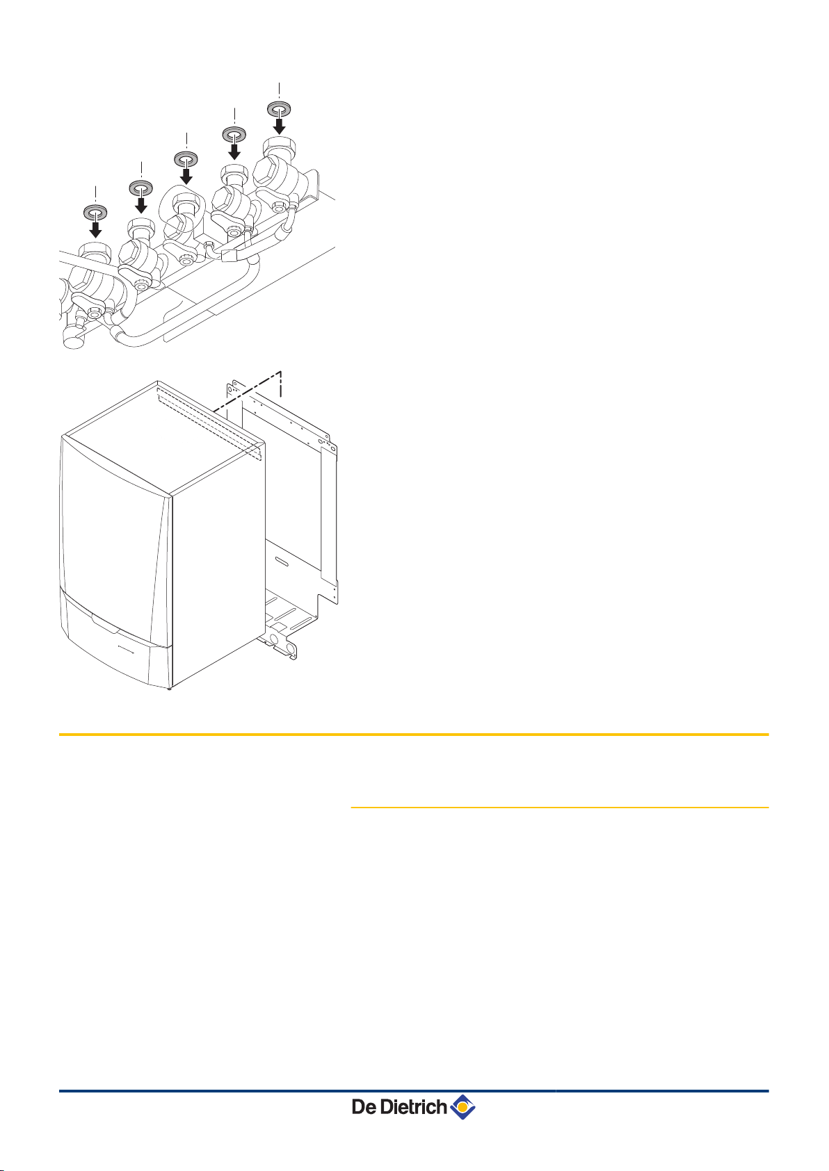
2. Fit a fibre gasket to each joint on the valve plate.
3. Position the boiler above the plumbing fixtures plate and locate it
against the mounting frame. Gently lower the boiler.
4. Tighten the valve nuts on the boiler.
4.6 Hydraulic connections
20
4.6.1. Flushing the system
Installation must be carried out in accordance with the prevailing
regulations, the codes of practice and the recommendations in these
instructions.
Installing the boiler in new installations (installations less than
6 months old)
4 Clean the installation with a universal cleaner to eliminate debris
from the appliance (copper, hemp, flux).
4 Thoroughly flush the installation until the water runs clear and
shows no impurities.
Installing the boiler in existing installations
4 Remove sludge from the installation.
15/06/12 - 300022159-001-01
T001625-A
T001633-B
MCA 25/28 BIC
4. Installation
4 Flush the installation.
4 Clean the installation with a universal cleaner to eliminate debris
from the appliance (copper, hemp, flux).
4 Thoroughly flush the installation until the water runs clear and
shows no impurities.
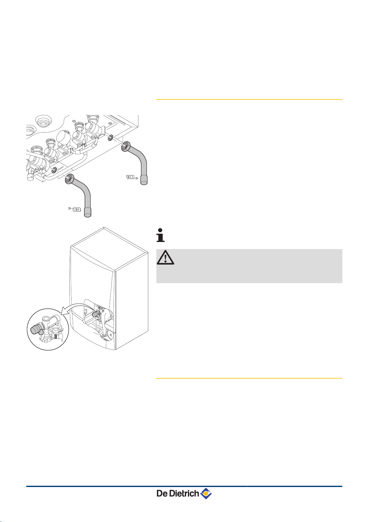
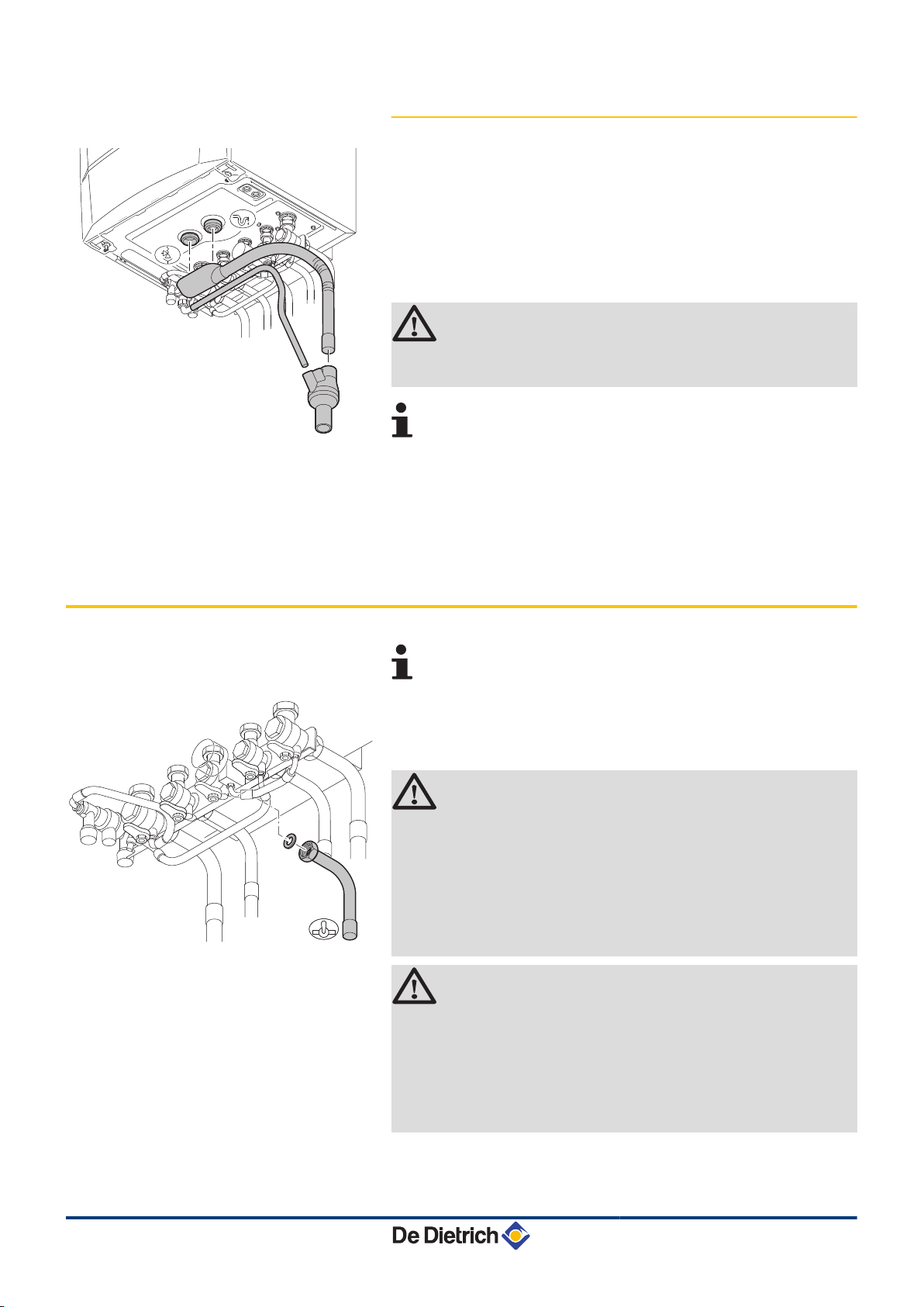
4.6.2. Connection of the heating circuit
{
z
Connection by internal brazing ∅ 22 mm
Connection by internal brazing ∅ 22 mm
1. Connect the heating water outlet pipe to the heating flow
connection.
2. Connect the heating water return pipe to the heating return
connection.
4 The boiler is factory fitted with a safety valve mounted
on the left hydroblock.
CAUTION
4 The heating pipe must be mounted in accordance
with prevailing provisions.
15/06/12 - 300022159-001-01
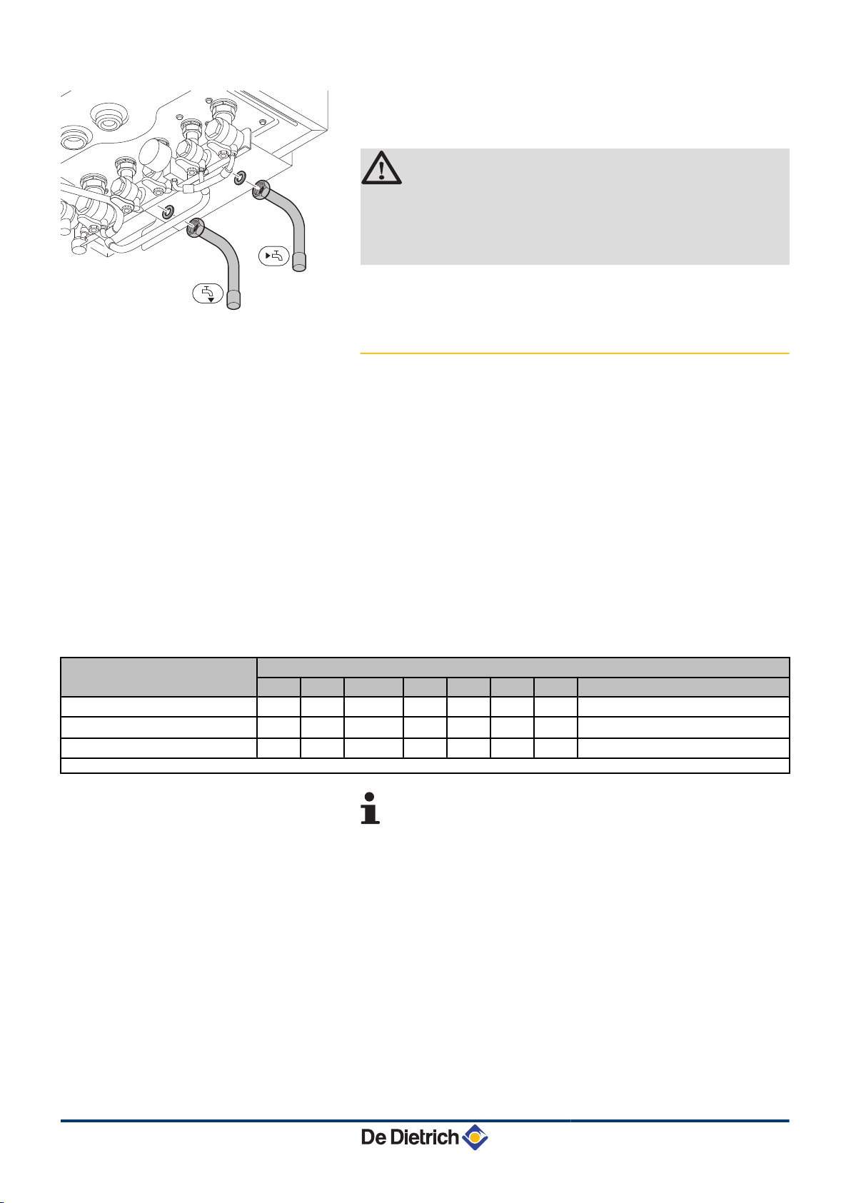
4.6.3. Connection of the water circuit for
domestic use
1. Connect the cold water inlet pipe to the domestic cold water
connection.
2. Connect the domestic hot water outlet pipe to the domestic hot
water connection.
21
T001626-B
4. Installation MCA 25/28 BIC
x
y
Connection by internal brazing ∅ 16 mm
Connection by internal brazing ∅ 16 mm
CAUTION
4 The domestic water pipes must be connected in
accordance with prevailing provisions.
4 If using synthetic pipes, follow the manufacturer's
(connection) instructions.
4.6.4. Connecting the expansion vessel
The boiler is fitted as standard with an 12-litre expansion vessel.
If the water volume is greater than 150 litres or the static height of the
system exceeds 5 metres, an additional expansion vessel must be
fitted. Refer to the table below to determine the expansion vessel
required for the installation.
Conditions of validity of the table:
4 3-bar safety valve
4 Average water temperature: 70 °C
Supply temperature: 80 °C
Return temperature: 60 °C
4 The filling pressure in the system is lower than or equal to the initial
pressure in the expansion vessel
Initial pressure of the
expansion vessel
0.5 bar 4,8 6,0 7,2 8,4 9,6 12,0 14,4 Volume of the installation x 0,048
1 bar 8,0 10,0
1.5 bar 13,3 16,6 20,0 23,3 26,6 33,3 39,9 Volume of the installation x 0,133
(1) Factory configuration
Volume of the expansion vessel depending on the volume of the installation (in litres)
100 125 150 175 200 250 300 > 300
(1)
12,0
14,0 16,0 20,0 24,0 Volume of the installation x 0,080
It is possible to fit the boiler with an expansion vessel for
DHW (package option HG77) under the integrated
expansion vessel for heating.
22
15/06/12 - 300022159-001-01
T001873-C
T001621-A
MCA 25/28 BIC 4. Installation
4.6.5. Connecting the condensate discharge pipe
1. Mount a standard drainage pipe, Ø 32 mm or more, leading to the
mains drainage system.
2. Mount the flow collector.
3. Into this, insert the condensate collector hose coming from the
siphon j and the safety valve ê.
4. Into this, insert the discharge hose from the disconnector.
5. Mount a trap or a siphon in the discharge pipe.
CAUTION
Do not make a fixed connection owing to maintenance
work on the siphon.
4 Do not plug the condensate discharge pipe.
4 Set the discharge pipe at a gradient of at least 30 mm
per metre, maximum horizontal length 5 metres.
4 Do not drain condensation water into a roof gutter at
any time.
4 Connect the condensate discharge pipe in
accordance with prevailing standards.
4.7 Gas connection
The diameters of the pipes must be defined in accordance
with the standards in force in your country.
g
Connection by internal brazing ∅ 18 mm
1. Connect the gas inlet pipe.
WARNING
4 Close the main gas valve before starting work on the
gas pipes.
4 Before mounting, check that the gas meter has
sufficient capacity. To do this, you should keep in
mind the consumption of all domestic appliances.
4 If the gas meter has too low a capacity, inform the
energy supply company.
CAUTION
4 Ensure that there is no dust in the gas pipe. Blow into
the pipe or shake it before mounting.
4 We recommend installing a gas filter on the gas pipe
to prevent clogging of the gas valve unit.
4 Connect the gas pipe in accordance with prevailing
standards and regulations.
15/06/12 - 300022159-001-01
23
9
4
2
22
4
4
3
6 8
5
5
5
7
7
7
C
33(x)
C
33(x)
C
43(x)
C
83(x)
C
43(x)
C
43(x)
C
13(x)
C
53
C
83(x)
C
83(x)
C
33(x)
B
23P
B
23P
C
93(x)
C
93(x)
1
1
B
33
B
33
C002339-C
4. Installation MCA 25/28 BIC
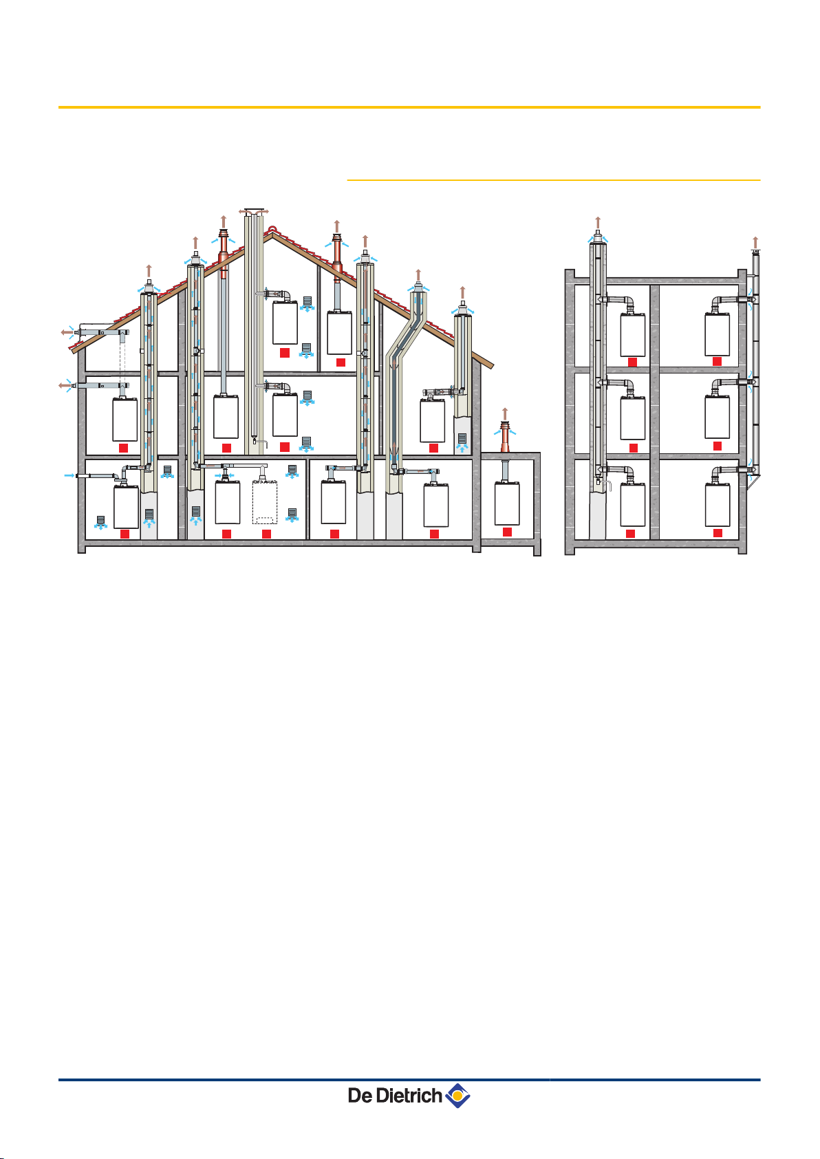
4.8 Flue gas system connections
4.8.1. Classification
1
Configuration B
33
Connection to a collective pipe via a concentric pipe
(combustive air taken from the boiler room)
All of the pressurised parts of the appliance are
surrounded by air.
2
Configuration B23 - B
23P
Connection to a chimney using a connection kit
(combustive air taken from the boiler room)
3
Configuration C
13(x)
Air/flue gas connection by means of concentric pipes to a
horizontal terminal (so-called forced flue)
4
Configuration C
33(x)
Air/flue gas connection by means of concentric pipes to a
vertical terminal (roof outlet)
5
Configuration C
43(x)
Air/flue gas connection to a collective conduit for
watertight boilers (3CE P system)
7
6
Configuration C
Air and flue gas connection separated by means of a bi-
53
flow adapter and single pipes (combustive air taken from
outside)
Configuration C
83(x)
Flue gas connection to a collective conduit for sealed
boilers. The air supply is individual via a terminal coming
from outside the building.
24
15/06/12 - 300022159-001-01
MCA 25/28 BIC 4. Installation
8
Configuration C
93(x)
Air/flue gas connection by concentric pipes in the boiler
room and single pipes in the chimney (combustive air in
counter current in the chimney)
9
Configuration C
93(x)
Air/flue gas connection by concentric pipes in the boiler
room and single flex in the chimney (combustive air in
counter current in the chimney)
WARNING
4 Only factory components are authorised for
connecting the boiler and the terminal.
4 The clear section must comply with the
standard.
4 The chimney must be swept before the
installation of the evacuation conduit.
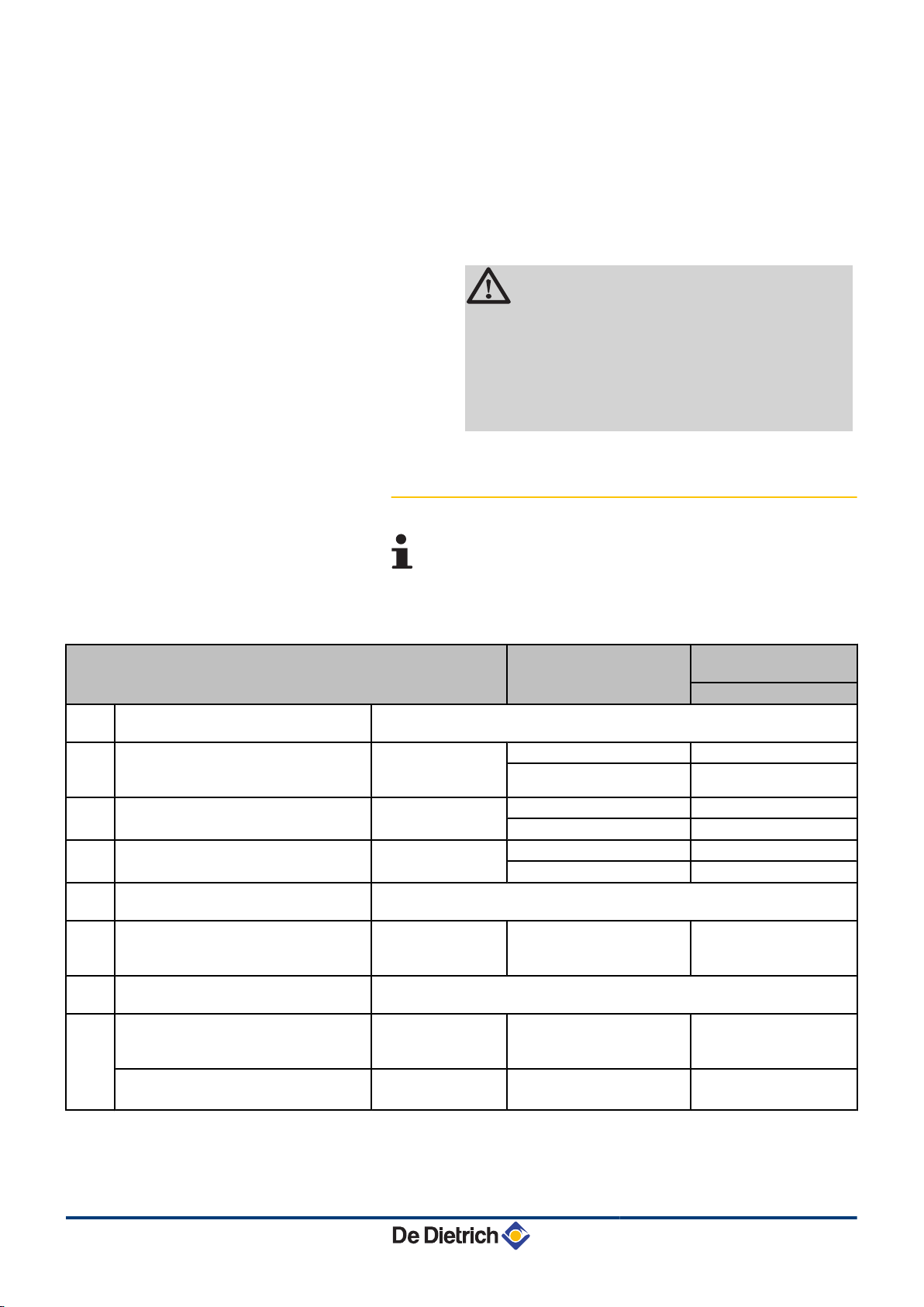
4.8.2. Lengths of the air/flue gas pipes
For configurations B23 and C93, the lengths given in the
table are valid for horizontal conduits with a maximum
length of 1 metre. For each additional metre of horizontal
conduit, subtract 1.2 m from the vertical length Lmax
Type of air/flue gas connection Diameter Maximum length in
metres
MCA 25/28 BIC
B
B
B
C
C
C
C
C
C
Collective conduit To determine the dimensions of such a system, refer to the supplier of the
33
Chimney (rigid or flexible duct in
23
chimney, combustive air taken from the
23P
premises)
Concentric pipes connected to a
13(x)
horizontal terminal
Concentric pipes connected to a vertical
33(x)
terminal
Collective conduit for sealed boiler (3
43(x)
CEP)
Bi-flow adapter and separate single air/
53
flue gas ducts (combustive air taken
from outside)
Collective conduit for sealed boiler To determine the dimensions of such a system, refer to the supplier of the
83(x)
Concentric pipes in the boiler room
93(x)
Single conduits in the chimney
(combustive air in counter-current)
Concentric pipes in the boiler room
Flexible single conduit in the chimney
collective conduit.
PPS 80 mm (Rigid duct) 40.0
80 mm (Flexible duct) 40.0
Alu or PPS 60/100 mm 4.2
80/125 mm 20.0
Alu or PPS 60/100 mm 5.5
80/125 mm 20.0
To determine the size of such a system, consult the supplier of the 3 CEP
conduit.
Alu 60/100 mm
2 x 80 mm
collective conduit.
Alu or PPS 60/100 mm
60 mm (Rigid duct)
PPS 60/100 mm
80 mm (Flexible duct)
40.0
9.0
20.0
15/06/12 - 300022159-001-01
25

4. Installation
MCA 25/28 BIC
WARNING
Maximum length = lengths of the straight air/flue gas ducts
+ equivalent lengths of other components
The max length in the flue gas pipe (configurations C93, B
23P
) of the
elbow bracket at the outlet must not exceed:
4 30 m for rigid PPS
4 25 m for flexible PPS
If longer lengths are used, holding clamps must be added per sections
of 25 or 30 metres.
For the list of flue gas system accessories and the equivalent lengths,
refer to the current price list.
4.8.3. Additional Directives
4 Please refer to the manufacturer's instructions for the material in
question when installing the flue gas discharge and air supply
materials. If the flue gas discharge and air supply materials are not
installed according to the instructions (e.g. they are not leakproof,
not clamped in place etc.), this may cause hazardous situations
and/or result in bodily injury. After assembly, check at least all flue
gas and air–carrying parts for tightness.
4 Connection of the combustion gas exhaust directly to the buildings
brick chimneys or flues is forbidden for condensation reasons.
4 Always clean the ducts thoroughly in cases where lining pipes are
used and/or a connection of the air-supply.
4 It must be possible to inspect the flue or chimney.
4 .
4 For long, aluminium, combustion-gas exhaust pipes it is initially
necessary to consider the relatively high quantity of corrosive
products which are brought together with the condensate from the
exhaust pipe. The siphon on the equipment requires regular
cleaning or, preferably, an additional condensate collector can be
installed above the equipment.
4 The combusted gas discharge pipe must be sufficiently inclined
towards the boiler (at least 50 mm per metre) and an adequate
condensate collection tank and discharge system constructed (at
least 1 m before the boiler opening). The elbows fitted must be at
more than 90° to guarantee the provision of an adequate gradient
and tightness on the lip rings.
26
15/06/12 - 300022159-001-01
8800N001-C
8800N002-C
MCA 25/28 BIC
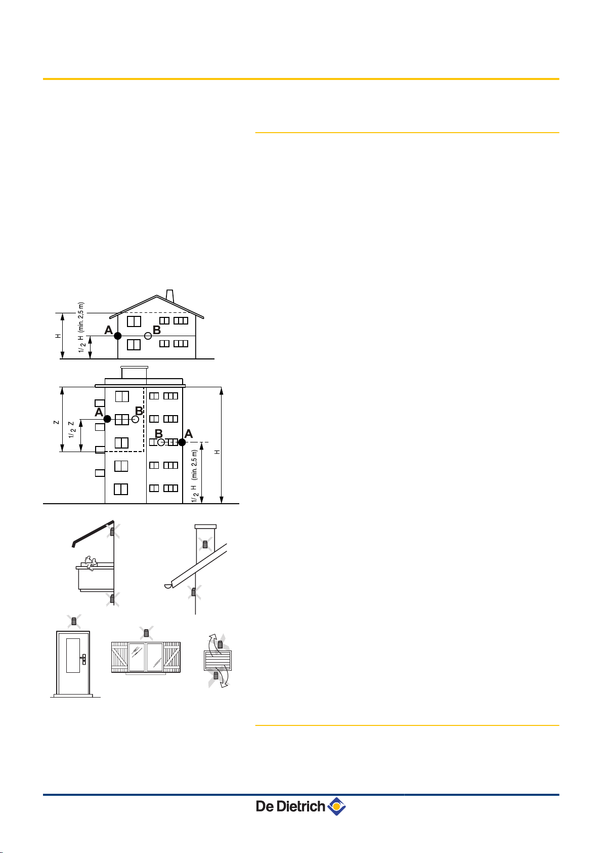
4.9 Installing the outside sensor
4.9.1. Choice of the location
It is important to select a place that allows the sensor to measure the
outside conditions correctly and effectively.
Advised positions:
4 on one face of the area to be heated, on the north if possible
4 half way up the wall in the room to be heated
4 under the influence of meteorological variations
4 protected from direct sunlight
4 easy to access
4. Installation
A
B
H
Z
Recommended position
Possible position
Inhabited height controlled by the sensor
Inhabited area controlled by the sensor
Positions to be avoided:
4 masked by a building element (balcony, roof, etc.)
4 close to a disruptive heat source (sun, chimney, ventilation grid,
etc.)
15/06/12 - 300022159-001-01
4.9.2. Connecting the outside sensor
Mount the sensor using the screws and dowels provided.
27
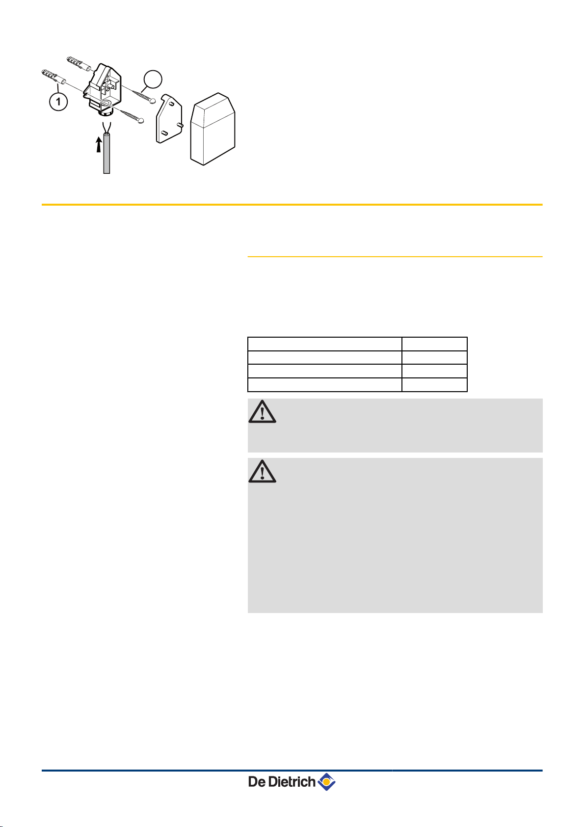
8800N003-C
2
4. Installation MCA 25/28 BIC
4.10 Electrical connections
A
Z
Inserts
Ø4 wood screw
¼ For the connection of the outside temperature sensor, refer to
the chapter "Electrical Connections".
4.10.1. Control unit
The boiler is fully pre-wired. The mains supply is made via the cable
C connected to the mains. All other external connections can be made
to the connection connectors (low voltage). The main characteristics
of the control unit are described in the table below.
Power supply voltage 230 VAC/50Hz
Rating of the main fuse F1 (230 VAC) 6.3 AT
Fuse rating F2 (230 VAC) 2 AT
Fan-DC 27 VDC
CAUTION
Keep to the polarity shown on the terminals: phase (L),
neutral (N) and earth *.
CAUTION
The following components of the appliance are at a
voltage of 230 V:
4 Boiler pump (Heating circuit).
4 Boiler pump (DHW circuit).
4 Combined venturi and gas valve unit.
4 3-way valve.
4 The majority of components in the control panel and
the terminal box.
4 Power supply cable.
28
15/06/12 - 300022159-001-01
 Loading...