

DeDietrich Innovens MCA 15, Innovens MCA 25/28 MI, Innovens MCA 25 Installation And Service Manual
Page 1
Innovens
Wall-hung gas condensing boilers
MCA 15 - MCA 25
MCA 25/28 MI
EN
Installation and
Service Manual
300022146-001-B
Page 2

EG - VERKLARING VAN OVEREENSTEMMING
EC - DECLARATION OF CONFORMITY
EG - KONFORMITÄTSERKLÄRUNG
DÉCLARATION DE CONFORMITÉ CE
Fabrikant/Manufacturer/Hersteller/Fabricant : Remeha B.V.
Adres/Address /Adresse : Kanaal Zuid 110
Stad,Land/City,Country/Land,Ort/Ville, pays : Postbus 32, NL-7300 AA Apeldoorn
verklaart hiermede dat de toestel(len) : MCA ../.. (MI) (BIC)
this is to declare that the following product(s) :
erklärt hiermit das die Produk(te) :
déclare ici que les produit(s) suivant(s) :
op de markt gebracht door : De Dietrich Thermique
distributor : 57, rue de la Gare, F-67580
Vertreiber :
Commercialisé (s) par :
voldoet/voldoen aan de bepalingen van de onderstaande EEG-richtlijnen:
is/are in conformity with the following EEC-directives:
den Bestimmungen der nachfolgenden EG-Richtlinien entspricht/entsprechen:
répond/répondent aux directives CEE suivantes:
EEG-Richtlijn: 90/396/EEG toegepaste normen:
EEC-Directive: 90/396/EEC tested and examined to the following norms:
EG-Richtlinie: 90/396/EWG verwendete Normen, normes appliquées:
CEE-Directive: 90/396/CEE EN 297
(1994*), 483(1999*), 677(1998*)
92/42/EEG
92/42/EEC
92/42/EWG
92/42/CEE
2006/95/EEG
EN 50165(1997*), EN 60335-1(1994*)
2006/95/EEC EN 60335-2-102(2004*) 08
2006/95/EWG
2006/95/CEE
2004/108/EEG
EN 50165(1997*)
2004/108/EEC EN 55014-2
(1997*), EN 55014-1(2000*),
2004/108/EWG EN 61000-3-2(2000*) , 61000-3-3(1995*)
2004/108/CEE
97/23/EEG (art. 3, lid 3)
97/23/EEC (article 3, sub 3)
97/23/EWG (Art. 3, Abzats 3)
97/23/CEE (art.3 section 3)
*) inclusief (eventuele) aanvulling, including (if any) competion
einschließlich (falls vorhanden) Vervollständigung, y compris (le cas échéant) complément
Apeldoorn, decembre 2009
W.F. Tijhuis
Approval manager
703/2009/12/128
C002860-A
MCA 15 - MCA 25 MCA 25/28 MI
Declaration of conformity
The appliance complies with the standard model described in
declaration of compliance [. It is manufactured and distributed
pursuant to the requirements of european directives.
The original of the declaration of compliance is available from the
manufacturer.
Page 3

Contents
1 Introduction ................................................................................................6
1.1 Used symbols .......................................................6
1.2 Abbreviations ........................................................6
1.3 General ..................................................................7
1.3.1 Manufacturer's liability .............................................7
1.3.2 Installer's liability .....................................................7
1.4 Homologations ......................................................7
1.4.1 Certifications ...........................................................7
1.4.2 Gas categories ........................................................8
1.4.3 Additional Directives ................................................8
1.4.4 Factory test .............................................................8
2 Safety instructions and recommendations ..............................................9
2.1 Safety instructions ...............................................9
2.2 Recommendations ................................................9
3 Technical description ..............................................................................11
3.1 General description ............................................11
3.2 Main parts ............................................................11
3.3 Operating principle .............................................12
3.3.1 Skeleton Diagrams ................................................12
3.3.2 Shunt pump ...........................................................12
3.3.3 Water flow rate ......................................................13
3.4 Technical characteristics ...................................13
3.4.1 Sensor characteristics ...........................................14
4 Installation ................................................................................................16
4.1 Regulations governing installation ...................16
4.2 Package list .........................................................16
4.2.1 Standard delivery ..................................................16
4.2.2 Accessories ...........................................................16
29/04/2010 - 300022146-001-B
4.3 Choice of the location ........................................17
4.3.1 Data plate ..............................................................17
4.3.2 Location of the appliance ......................................18
4.3.3 Ventilation .............................................................18
4.3.4 Main dimensions ...................................................19
1
Page 4

MCA 15 - MCA 25 MCA 25/28 MI
Contents
4.4 Installing the mounting frame ...........................20
4.5 Positioning the boiler .........................................21
4.6 Hydraulic connections .......................................22
4.6.1 Flushing the system ..............................................22
4.6.2 Connection of the heating circuit ...........................22
4.6.3 Hydraulic connection of the water circuit for domestic
use ........................................................................23
4.6.4 Connecting the expansion vessel .........................23
4.6.5 Connecting the condensate discharge pipe ..........24
4.6.6 Filling the siphon ...................................................24
4.7 Gas connection ...................................................25
4.8 Flue gas system connections ............................26
4.8.1 Classification .........................................................26
4.8.2 Lengths of the air/flue gas pipes ...........................27
4.9 Installing the outside sensor .............................28
4.9.1 Choice of the location ............................................28
4.9.2 Installing the outside sensor ..................................28
4.10 Electrical connections ........................................29
4.10.1 Control unit ............................................................29
4.10.2 Recommendations ................................................30
4.10.3 Position of the PCBs .............................................31
4.10.4 Accessing the connection terminal blocks ............32
4.10.5 Connecting a direct heating circuit ........................34
4.10.6 Connecting a direct heating circuit and a domestic hot
water tank ..............................................................35
4.10.7 Connecting two circuits and a domestic hot water tank
before the mixing tank ...........................................37
4.10.8 Connecting two circuits and a domestic hot water tank
after the mixing tank ..............................................39
4.10.9 Hot water storage tank connection ........................41
4.10.10 Pool connection .....................................................46
4.10.11 Connecting a mixed tank .......................................48
4.10.12 Connecting the options .........................................49
4.10.13 Connection in cascade ..........................................50
4.11 Electrical diagram ...............................................53
4.12 Filling the system ...............................................54
4.12.1 Water treatment ....................................................54
4.12.2 Filling the system ..................................................56
5 Start-up ......................................................................................................57
5.1 Control panel .......................................................57
5.1.1 Description of the keys ..........................................57
5.1.2 Description of the display ......................................58
5.1.3 Access to the various browsing levels ..................60
5.1.4 Browsing in the menus ..........................................62
5.2 Check points before commissioning ................63
5.2.1 Preparing the boiler for commissioning .................63
29/04/2010 - 300022146-001-B
2
Page 5

5.2.2 Gas circuit .............................................................64
5.2.3 Hydraulic circuit .....................................................64
5.2.4 Electrical connections ...........................................64
5.3 Putting the appliance into operation ................65
5.4 Gas settings ........................................................66
5.4.1 Adapting to another gas type ................................66
5.4.2 Setting the air/gas ratio (Full load) ........................67
5.4.3 Setting the air/gas ratio (Part load) ......................69
5.4.4 Basic setting for the gas/air ratio ...........................71
5.5 Checks and adjustments after
commissioning ...................................................71
5.5.1 Displaying the parameters in extended
mode .....................................................................71
5.5.2 Setting the parameters specific to the
installation .............................................................72
5.5.3 Naming the circuits and generators ......................75
5.5.4 Setting the heating curve ......................................76
5.5.5 Finalizing work ......................................................78
5.6 Reading out measured values ...........................78
5.7 Changing the settings ........................................79
5.7.1 Language selection ...............................................80
5.7.2 Calibrating the sensors .........................................80
5.7.3 "Professional" settings ..........................................82
5.7.4 Configuring the network ........................................88
5.7.5 Returning to the factory settings ...........................96
6 Switching off the appliance .....................................................................97
6.1 Installation shutdown .........................................97
6.2 Frost protection ..................................................97
7 Checking and maintenance .....................................................................98
7.1 General instructions ...........................................98
7.2 Chimney sweep instructions .............................98
7.3 Customising maintenance .................................99
7.3.1 Maintenance message ..........................................99
7.3.2 Installer's contact details .....................................100
29/04/2010 - 300022146-001-B
7.4 Standard inspection and maintenance
operations .........................................................100
7.4.1 Checking the hydraulic pressure .........................101
7.4.2 Checking the opened expansion vessel ..............101
7.4.3 Checking the ionisation current ...........................101
7.4.4 Checking the transfer capacity ............................101
7.4.5 Checking the tightness of the combusted gases
evacuation and air inlet connections ...................101
7.4.6 Checking combustion ..........................................102
7.4.7 Checking the automatic air vent ..........................103
3
Page 6

MCA 15 - MCA 25 MCA 25/28 MI
7.4.8 Checking the safety valve ...................................104
7.4.9 Checking the siphon ............................................104
7.4.10 Checking the burner and cleaning the heat
exchanger ...........................................................105
Contents
7.5 Specific maintenance operations ....................106
7.5.1 Replacing the ionisation/ignition electrode ..........106
7.5.2 Cleaning the plate exchanger (domestic hot water
end) and the water filter cartridge .......................106
7.5.3 Replacing the 3-way valve ..................................109
7.5.4 Replacing the non-return valve ...........................110
7.5.5 Assembling the boiler ..........................................111
8 Troubleshooting .....................................................................................112
8.1 Messages (Code type Bxx or Mxx) ..................112
8.2 Message history ................................................114
8.3 Faults (Code type Lxx or Dxx) .........................115
8.3.1 Deletion of sensors from the memory in the
PCB .....................................................................123
8.3.2 Deleting the IOBL 3WV modules from the memory in
the PCB ..............................................................123
8.4 Failure history ...................................................124
8.5 Parameter and input/output check (mode
tests) ..................................................................125
9 Spare parts ..............................................................................................129
9.1 General ..............................................................129
9.2 Spare parts ........................................................129
9.2.1 Casing .................................................................130
9.2.2 Heat exchanger and burner ................................131
9.2.3 Fan ......................................................................132
9.2.4 Control panel .......................................................133
9.2.5 Connecting pipes (MCA 15 - MCA 25) ................134
9.2.6 Connecting pipes (MCA 25/28 MI) ......................135
9.2.7 Spare parts list ....................................................136
29/04/2010 - 300022146-001-B
4
Page 7

29/04/2010 - 300022146-001-B
5
Page 8
1. Introduction
1 Introduction
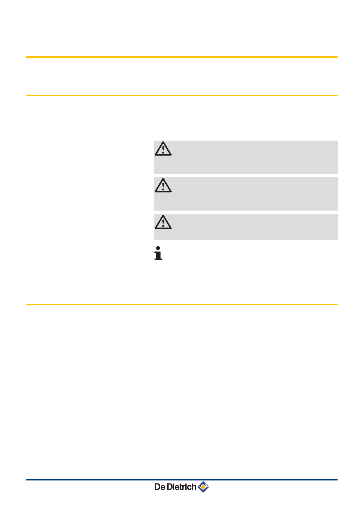
1.1 Used symbols
MCA 15 - MCA 25 MCA 25/28 MI
In these instructions, various danger levels are employed to draw the
user's attention to particular information. In so doing, we wish to
safeguard the user's safety, obviate hazards and guarantee correct
operation of the appliance.
DANGER
Risk of a dangerous situation causing serious physical
injury.
WARNING
Risk of a dangerous situation causing slight physical
injury.
1.2 Abbreviations
CAUTION
Risk of material damage.
Signals important information.
¼ Signals a referral to other instructions or other pages in the
instructions.
4 3CE: Collective conduit for sealed boiler
4 DHW: Domestic hot water
4 Interscenario switch: Home automation switch that can be used
to centralise and control several scenarios
4 Hi: Lower heating value LHV
4 Hs: Higher heating value HHV
4 IOBL: Carrier current home automation bus
4 PPS: Polypropylene hardly inflammable
4 PCU: Primary Control Unit - PCB for managing burner operation
4 PSU: Parameter Storage Unit - Parameter storage for PCBs
PCU and SU
4 SCU: Secondary Control Unit - Diematic iSystem control panel
PCB
4 SU: Safety Unit - Safety PCB
4 3WV: 3-way valve
6
29/04/2010 - 300022146-001-B
Page 9

MCA 15 - MCA 25 MCA 25/28 MI 1. Introduction
1.3 General
1.3.1. Manufacturer's liability
Our products are manufactured in compliance with the requirements
of the various european applicable Directives. They are therefore
delivered with [ marking and all relevant documentation.
In the interest of customers, we are continuously endeavouring to
make improvements in product quality. All the specifications stated in
this document are therefore subject to change without notice.
Our liability as the manufacturer may not be invoked in the following
cases:
4 Failure to abide by the instructions on using the appliance.
4 Faulty or insufficient maintenance of the appliance.
4 Failure to abide by the instructions on installing the appliance.
1.4 Homologations
1.3.2. Installer's liability
The installer is responsible for the installation and inital start up of the
appliance. The installer must respect the following instructions:
4 Read and follow the instructions given in the manuals provided
with the appliance.
4 Carry out installation in compliance with the prevailing legislation
and standards.
4 Perform the initial start up and carry out any checks necessary.
4 Explain the installation to the user.
4 Warn the user of the obligation to check the appliance and
maintain it in good working order.
4 Give all the instruction manuals to the user.
1.4.1. Certifications
29/04/2010 - 300022146-001-B
CE identification no
NOx classification
Type of connection Chimney: B23 , B
PIN 0063BT3444
5 (EN 297 pr A3, EN 656)
Flue gas outlet: C13 , C33, C43, C53, C63, C83 , C
33
93
7
Page 10
1. Introduction
MCA 15 - MCA 25 MCA 25/28 MI
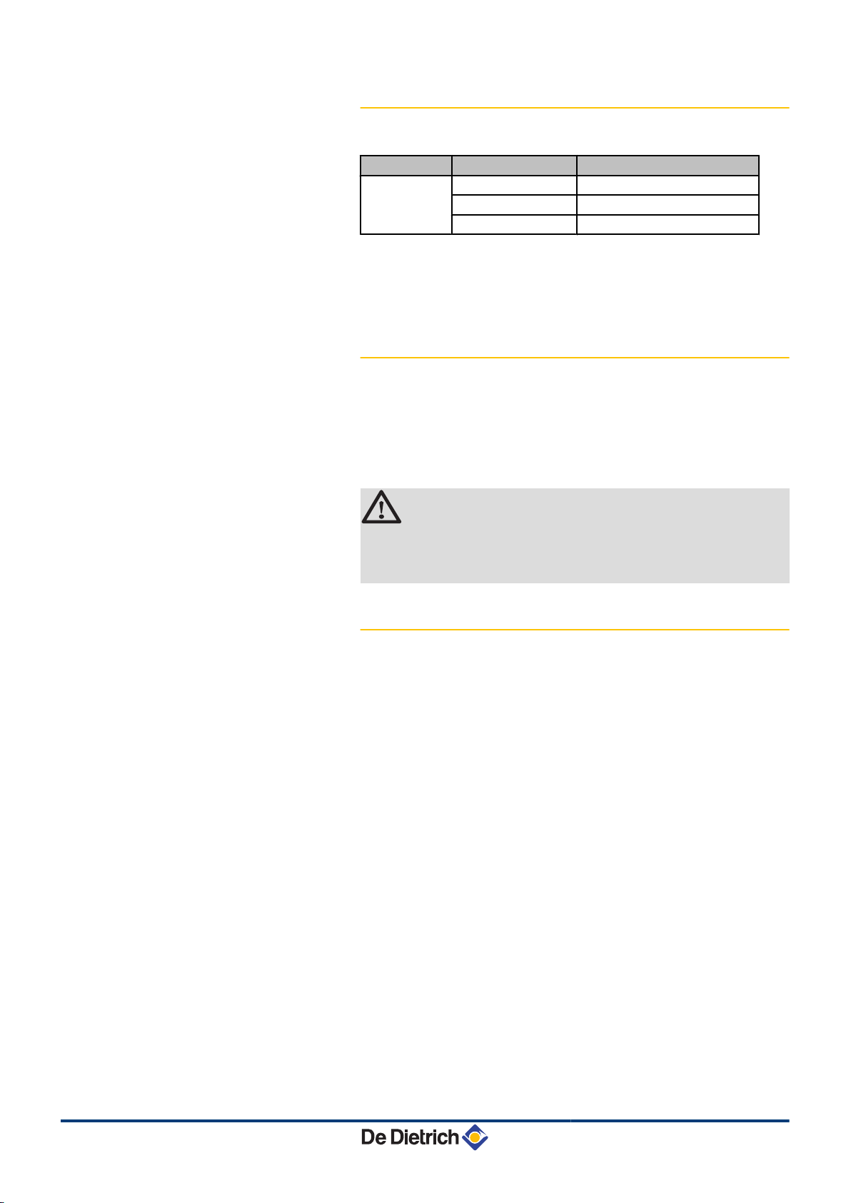
1.4.2. Gas categories
Gas category Gas type Connection pressure (mbar)
II
2ESi3P
Natural gas H (G20) 20
Natural gas L (G25) 25
Propane (G31) 37
The boiler is preset in the factory to operate on natural gas H (G20).
¼ For operation on another type of gas, see chapter: "Adapting
to another gas type", page 66.
1.4.3. Additional Directives
Apart from the legal provisions and Directives, the additional
Directives described in these instructions must also be observed.
For all provisions and Directives referred to in these instructions, it is
agreed that all addenda or subsequent provisions will apply at the
time of installation.
WARNING
Installation of the appliance must be done by a qualified
engineer in accordance with prevailing local and national
regulations.
1.4.4. Factory test
Before leaving the factory, each boiler is set for optimum performance
and tested to check the following items:
4 Electrical safety
4 Adjustment (CO2)
4 Domestic hot water mode (Only on models with domestic hot water
production)
4 Water tightness
4 Gas tightness
4 Parameter settings
8
29/04/2010 - 300022146-001-B
Page 11
MCA 15 - MCA 25 MCA 25/28 MI
2 Safety instructions and
recommendations
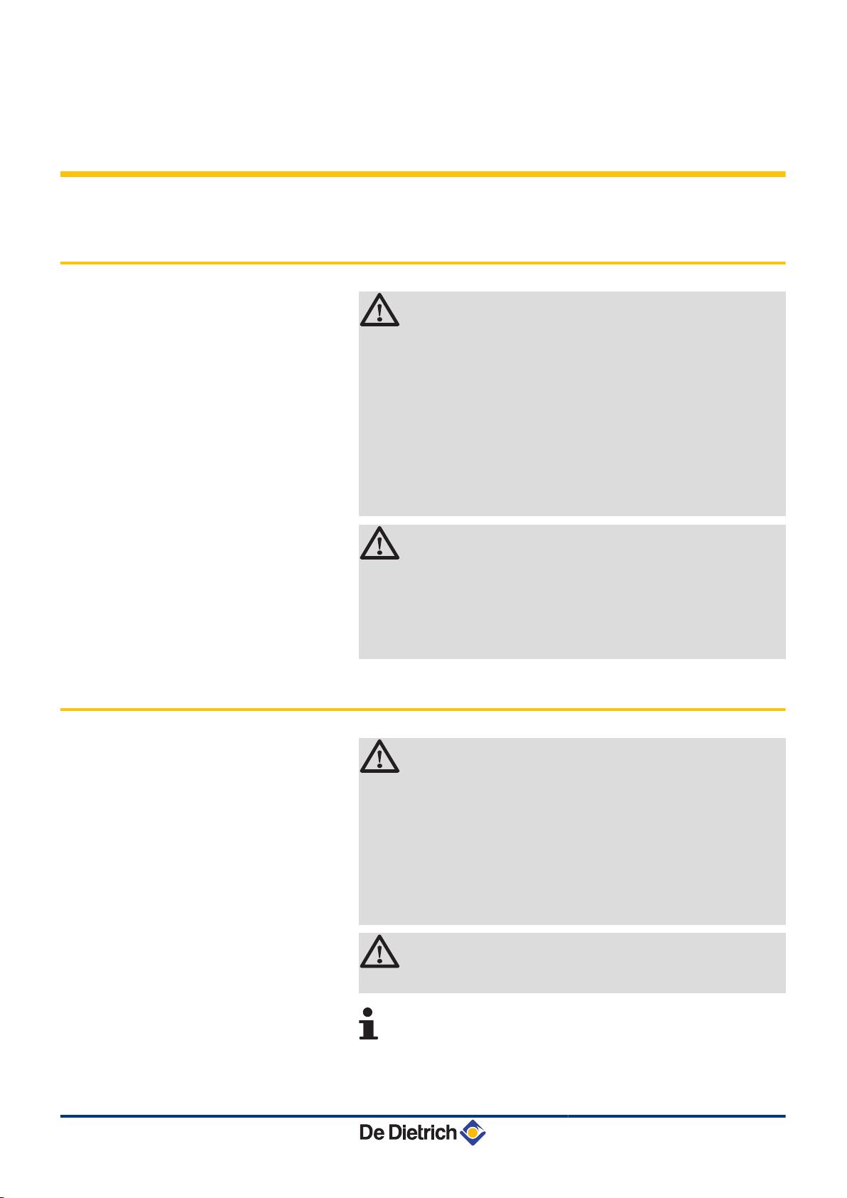
2.1 Safety instructions
DANGER
If you smell gas:
1. Do not use a naked flame, do not smoke, do not
operate electrical contacts or switches ( doorbell,
light, motor, lift, etc..).
2. Isolate the gas supply.
3. Open the windows.
4. Trace possible leaks and seal them immediately.
5. If the gas leak is before the gas meter, contact the
gas supplier.
2. Safety instructions and recommendations
2.2 Recommendations
DANGER
If you smell flue gases:
1. Switch the appliance off.
2. Open the windows.
3. Trace possible leaks and seal them immediately.
WARNING
4 Installation and maintenance of the boiler must be
carried out by a qualified professional in compliance
with prevailing local and national regulations.
4 When working on the boiler, always disconnect the
boiler from the mains and close the main gas inlet
valve.
4 After maintenance or repair work, check all
installations to ensure that there are no leaks.
CAUTION
29/04/2010 - 300022146-001-B
The boiler must be installed in a frost-free environment.
Keep this document close to the place where the boiler is
installed.
Casing components
9
Page 12

2. Safety instructions and recommendations MCA 15 - MCA 25 MCA 25/28 MI
Only remove the casing for maintenance and repair operations. Put
the casing back in place after maintenance and repair operations.
Instructions stickers
The instructions and warnings affixed to the appliance must never be
removed or covered and must remain legible during the entire lifespan
of the boiler. Immediately replace damaged or illegible instructions
and warning stickers.
Modifications
Modifications may only be made to the boiler after the written
permission of De Dietrich Thermique to do so.
10
29/04/2010 - 300022146-001-B
Page 13
T001867-C
2
15
14
13
16
17
18
19
20
21
3
4
5
6
7
8
9
10
11
12
1 22
MCA 15 - MCA 25 MCA 25/28 MI 3. Technical description
3 Technical description
3.1 General description
Wall-hung gas condensing boilers
4 High efficiency heating.
4 Low pollutant emissions.
4 Top of the range electronic DIEMATIC iSystem control panel
4 Installation and connection facilitated by the mounting frame
delivered with the appliance.
4 Flue gas discharge via a forced flue, chimney, bi-flow or 3CE type
connection.
4 MCA 15 - MCA 25: Heating only (Possibility of producing domestic
hot water via an independent tank which has been installed
separately).
4 MCA 25/28 MI: Heating and micro-storage domestic hot water
production.
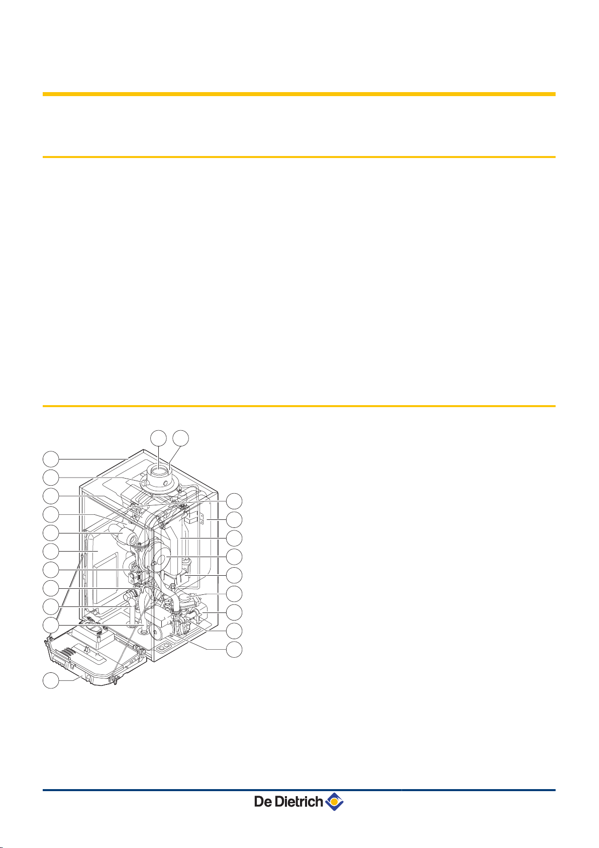
3.2 Main parts
1
2
3
4
5
6
7
8
9
10
11
12
13
14
15
16
17
18
19
Flue gas discharge pipe
Casing/air box
Outlet for measuring combustion gases
Mixer pipe
Heating flow hose
Áir intake silencer
Box for the control PCBs
Combined venturi and gas valve unit
Flow end hydrobloc
Safety valve outlet pipe
Siphon
Control panel
Shunt pump
Return end hydrobloc
Plate heat exchanger (DHW circuit) (Only on models with
domestic hot water production)
Inverter valve
Condensate receiver tank
Fan
Heat exchanger (Heating circuit)
29/04/2010 - 300022146-001-B
11
Page 14
T001868-B
1
2
3
10
9
8
4 5 6 7
T002537-B
0 200 400 600 800 1000 1200
Q (l/h)
10 kW
15 kW
20 kW
25 kW
615
545
435
295
437 623 830 1037
0
100
200
300
400
500
700
H (mbar)
600
3. Technical description
MCA 15 - MCA 25 MCA 25/28 MI
3.3 Operating principle
20
21
22
Expansion vessel
Ignition/ionization electrode
Air intake
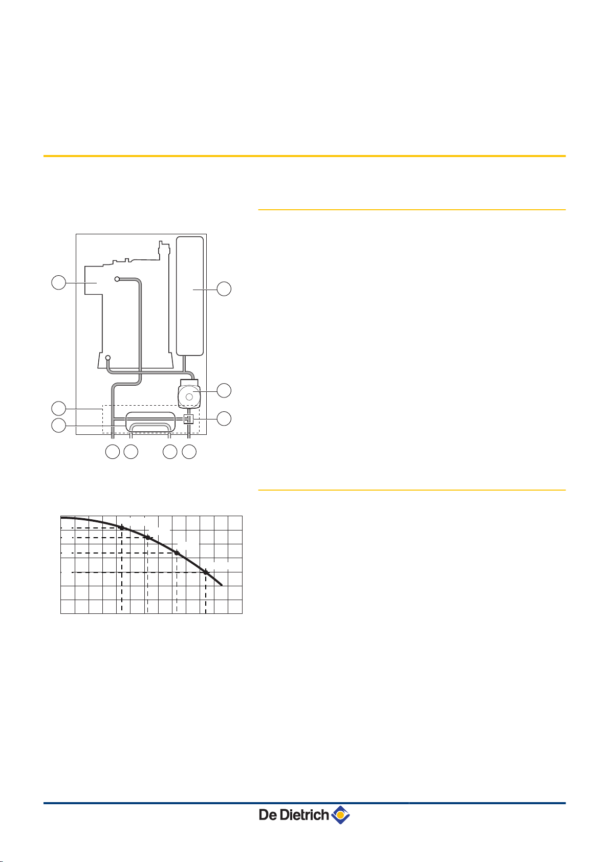
3.3.1. Skeleton Diagrams
1
2
3
4
5
6
7
Heat exchanger (Heating circuit)
Hydrobloc
Plate heat exchanger (DHW circuit) (Only on models with
domestic hot water production)
Heating flow
Domestic hot water outlet
Domestic cold water inlet
Heating return
8
9
10
Inverter valve
Shunt pump (Heating circuit)
Expansion vessel
3.3.2. Shunt pump
H
Q
The boiler is fitted with a modulating pump which is regulated by the
control panel as a fuction of ΔT.
The graph shows the manometric height at various outputs. The
parameters MIN.PUMP SPEED and MAX.PUMP SPEED are used to
modify the pump settings. If flow noise can be heard in the system, it
is possible to reduce the maximum pump speed with the parameter
MAX.PUMP SPEED (First of all, vent the heating system). If
circulation in the radiators is too low or the radiators do not fully heat
up, increase the minimum pump speed with the parameter
MIN.PUMP SPEED.
Manometric height central heating circuit
Water flow
12
¼ See chapter: ""Professional" settings", page 82.
29/04/2010 - 300022146-001-B
Page 15
T001978-A
0
100
200
300
400
500
600
700
0 500
1037437
15001000 2000 2500
∆p [mbar]
Q [l/h]
623 830
∆T = 20K
10 kW
15 kW
20 kW
25 kW
MCA 15 - MCA 25 MCA 25/28 MI 3. Technical description
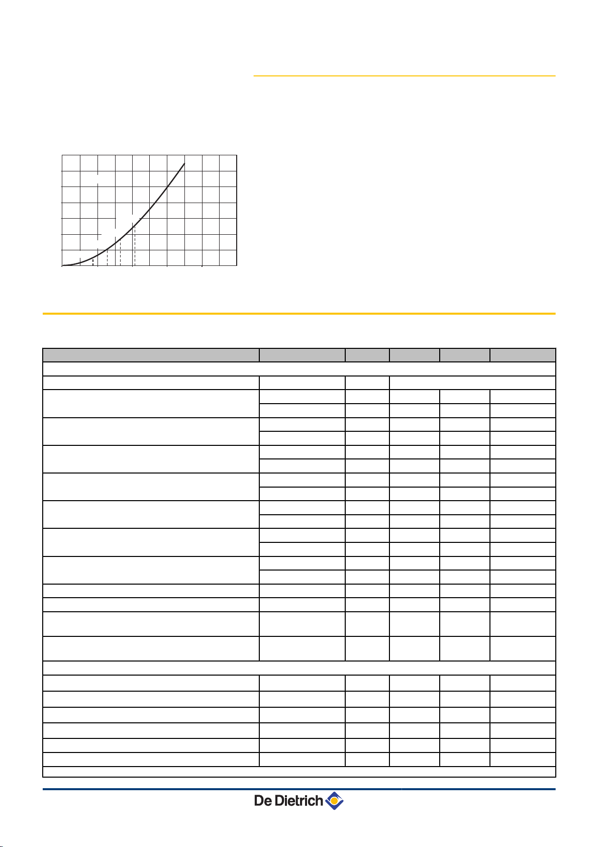
3.3.3. Water flow rate
The boiler's modulating control system limits the maximum difference
in temperature between the heating flow and return and the maximum
speed at which the flow temperature increases. In this way, the boiler
does not require a minimum water flow rate.
Δp
Q
Pressure drop
Water flow (max = 1680 l/h)
3.4 Technical characteristics
Boiler type
General
Flow rate setting Adjustable
Nominal output (Pn)
Heating System (80/60 °C)
Nominal output (Pn)
Heating System (50/30 °C)
Nominal output (Pn)
DHW System
Nominal input (Qn)
Heating System (Hi)
Nominal input(Qn)
Heating System (Hs)
Nominal input (Qnw)
DHW System (Hi)
Nominal input (Qnw)
DHW System (Hs)
minimum-maximum kW 3,0 - 14,5 5,0 - 24,1 5,0 - 24,1
Factory setting kW 14,5 24,1 19,4
minimum-maximum kW 3,4 - 15,8 5,6 - 25,5 5,6 - 25,5
Factory setting kW 15,8 25,5 20,5
minimum-maximum kW - - 5,0 - 28,6
Factory setting kW - - 28,6
minimum-maximum kW 3,1 - 15,0 5,2 - 25,0 5,2 - 25,0
Factory setting kW 15,0 25,0 20,1
minimum-maximum kW 3,4 - 16,7 5,8 - 27,8 5,8 - 27,8
Factory setting kW 16,7 27,8 22,3
minimum-maximum kW - - 5,2 - 28,0
Factory setting kW - - 28,0
minimum-maximum kW - - 5,8 - 31,1
Factory setting kW - - 31,1
Heating efficiency under full load (Hi) (80/60 °C) - % 96,5 96,3 96,3
Heating efficiency under full load (Hi) (50/30 °C) - % 105,3 102,0 102,0
Heating efficiency under partial load (Hi) (Return
- % 94,9 96,1 96,1
temperature 60°C)
Heating efficiency under partial load (EN 92/42)
- % 108,5 108,0 108,0
(Return temperature 30°C)
Data on the gases and combustion gases
Gas consumption - Natural gas H (G20) minimum-maximum
Gas consumption - Natural gas L (G25) minimum-maximum
Gas consumption - Propane G31 minimum-maximum
NOx-Emission per year or (n =1)
m3/h
m3/h
m3/h
mg/kWh 33 38 38
Mass flue gas flow rate minimum-maximum kg/h 5,3 - 25,2 8,9 - 42,1 8,9 - 47,1
Flue gas temperature minimum-maximum °C 30 - 65 30 - 80 30 - 85
(1) Front panel removed
29/04/2010 - 300022146-001-B
MCA 15 MCA 25 MCA 25/28 MI
Modulating, Start/Stop, 0 - 10 V
0,33 - 1,59 0,55 - 2,65 0,55 - 2,96
0,38 - 1,85 0,64 - 3,08 0,64 - 3,45
0,13 - 0,61 0,21 - 1,02 0,21 - 1,15
13
Page 16
3. Technical description MCA 15 - MCA 25 MCA 25/28 MI
Boiler type
Maximum counter pressure
Characteristics of the heating circuit
Water content
Water operating pressure minimum kPa (bar) 80 (0,8) 80 (0,8) 80 (0,8)
Water operating pressure (PMS) maximum kPa (bar) 300 (3,0) 300 (3,0) 300 (3,0)
Water temperature maximum °C 110 110 110
Operating temperature maximum °C 90 90 90
Manometric height central heating circuit (∆T = 20K)
Characteristics of the domestic hot water circuit
Specific hot water flow D (60 °C)
Specific hot water flow D (40 °C)
Domestic water resistance
Flow rate threshold minimum l/min - - 1,2
Water content
Operating pressure (Pmw) maximum kPa (bar) - - 800 (8,0)
Electrical characteristics
Power supply voltage
Power consumption - Full load
Power consumption - Part load maximum W 25 25 25
Power consumption - Standby maximum W 4 4 4
Electrical protection index
Other characteristics
Weight (empty)
Acoustic level at 1 meter at high speed
(1) Front panel removed
maximum W 101 116 124
Factory setting W 63 76 76
Pa 80 120 130
l 1,7 1,7 1,7
mbar 545 295 295
l/min - - 8,2
l/min - - 13,7
mbar - - 490
l - - 0,33
VAC 230 230 230
Total kg 43 43 44
Mounting
(1)
kg 36 36 37
dBA 35 42 44
MCA 15 MCA 25 MCA 25/28 MI
IPX4D IPX4D IPX4D
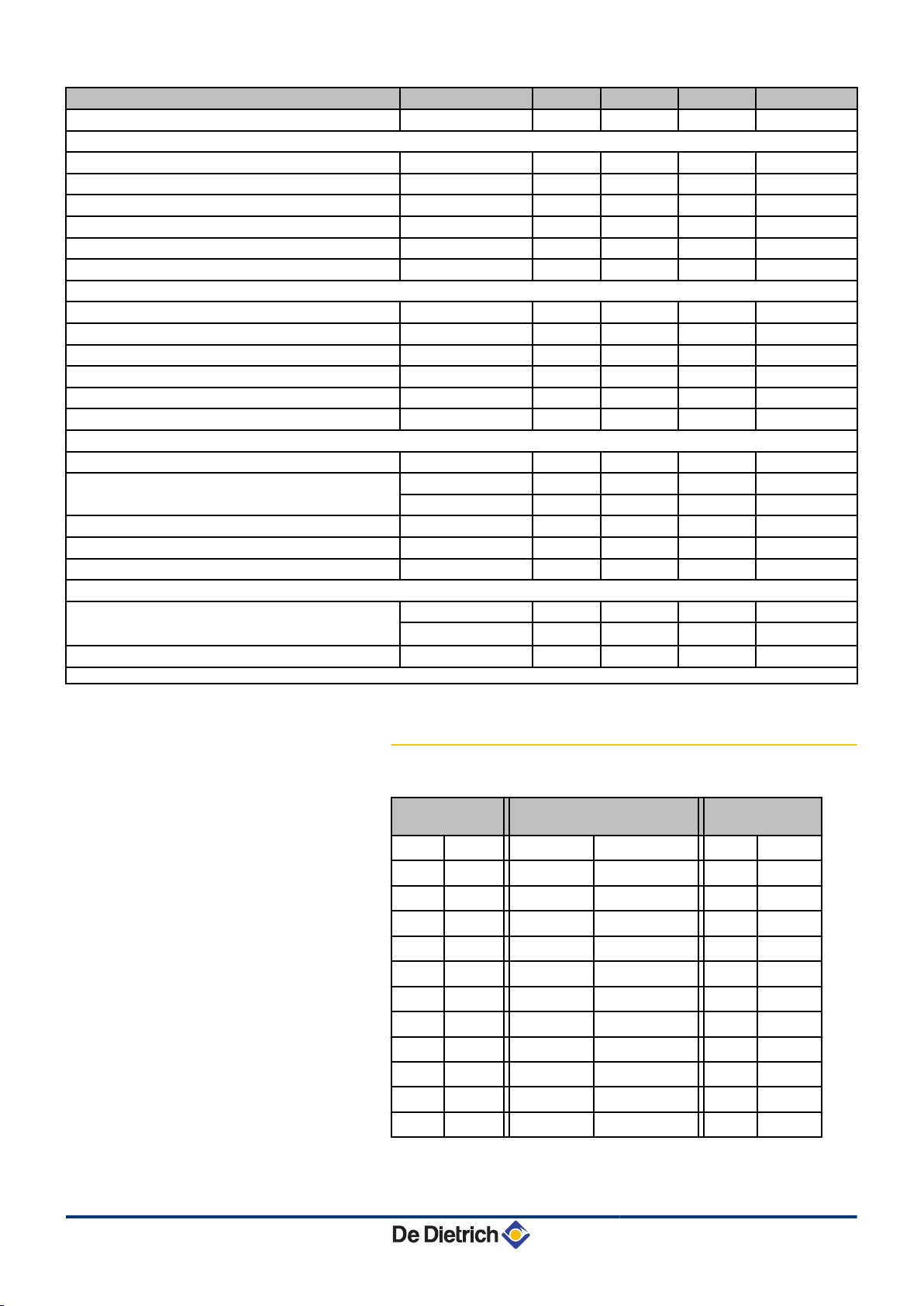
3.4.1. Sensor characteristics
Outside sensor
-20 °C
-16 °C
-12 °C
-8 °C
-4 °C
0 °C
4 °C
8 °C
12 °C
16 °C
20 °C
24 °C
2392 ¨
2088 ¨
1811 ¨
1562 ¨
1342 ¨
1149 ¨
984 ¨
842 ¨
720 ¨
616 ¨
528 ¨
454 ¨
Outlet sensor circuit B+C
Domestic hot water sensor
0 °C
10 °C
20 °C
25 °C
30 °C
40 °C
50 °C
60 °C
70 °C
80 °C
90 °C
32014 ¨
19691 ¨
12474 ¨
10000 ¨
8080 ¨
5372 ¨
3661 ¨
2535 ¨
1794 ¨
1290 ¨
941 ¨
Boiler sensor
Return sensor
-20 °C
-10 °C
0 °C
10 °C
20 °C
25 °C
30 °C
40 °C
50 °C
60 °C
70 °C
80 °C
98932 ¨
58879 ¨
36129 ¨
22804 ¨
14773 ¨
12000 ¨
9804 ¨
6652 ¨
4607 ¨
3252 ¨
2337 ¨
1707 ¨
14
29/04/2010 - 300022146-001-B
Page 17

MCA 15 - MCA 25 MCA 25/28 MI 3. Technical description
Outside sensor Outlet sensor circuit B+C
Domestic hot water sensor
Boiler sensor
Return sensor
90 °C
100 °C
110 °C
1266 ¨
952 ¨
726 ¨
29/04/2010 - 300022146-001-B
15
Page 18
4. Installation MCA 15 - MCA 25 MCA 25/28 MI
4 Installation
4.1 Regulations governing installation
WARNING
Installation of the appliance must be done by a qualified
engineer in accordance with prevailing local and national
regulations.
4.2 Package list
4.2.1. Standard delivery
The delivery includes:
4 The boiler, fitted with a connection cable
4 Mounting frame
4 Mounting template
4 Connection kit
4 Run-off collector for siphon and safety valve
4 Outside sensor
4 Installation and Service Manual
4 User Guide
4.2.2. Accessories
Various options are available depending on the configuration of the
installation:
Boiler options
Description package Description package
Stand-off frame HR39 RX12 cable AD134
Pipework kit for stand-off frame HR40 TELCOM 2 voice remote monitoring module AD152
Pipe cover HR42 Flow sensor AD199
Flue gas thermostat HR43 DHW sensor AD212
adapter 80/125 HR38 Optional PCB for 3-way valve AD249
adapter 80-80 HR46 Hot water storage tank sensor AD250
Exchanger cleaning kit HR44 Outside radio-controlled temperature sensor AD251
Boiler body cleaning kit HR45 Boiler radio module AD252
DHW tank BS60 EE54 Radio remote control AD253
Kit for connection between MCA and BS60 EA138 Interactive remote control AD254
Control system options
16
29/04/2010 - 300022146-001-B
Page 19
T001539-B
MCA 15 - MCA 25 MCA 25/28 MI 4. Installation
Boiler options Control system options
Description package Description package
DHW tank SR130 EE22 Room sensor FM52
Kit for connection between MCA and SR130 EA137
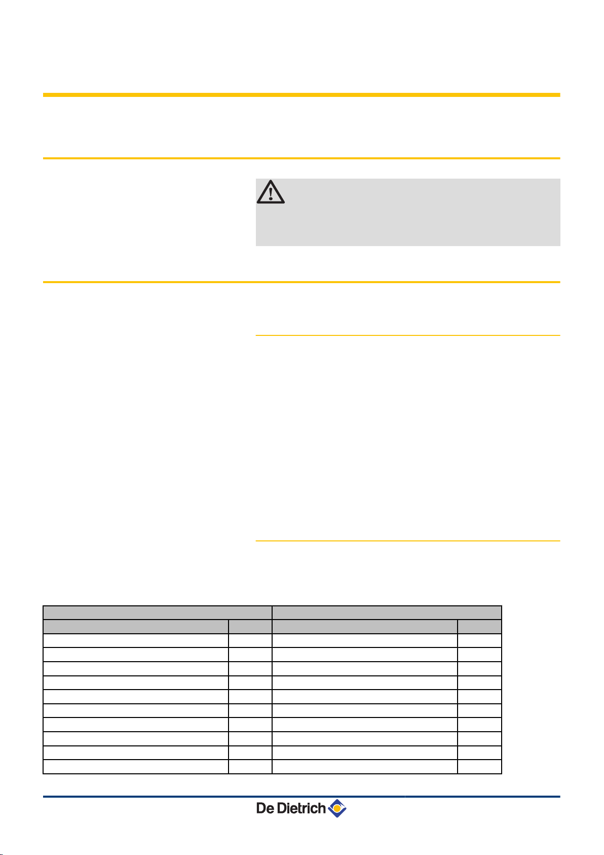
4.3 Choice of the location
4.3.1. Data plate
The data plate located on top of the boiler provides important
information on the appliance: serial number, model, gas category, etc.
29/04/2010 - 300022146-001-B
17
Page 20
T001583-A
450
min.1000
450
min.
250
min.
250
690
T001584-A
min. 550
min.550
min. 250
50 (2)
min. 250
100
min. (1)
4. Installation
MCA 15 - MCA 25 MCA 25/28 MI
4.3.2. Location of the appliance
4 Before mounting the boiler, decide on the ideal position for
mounting, bearing the Directives and the dimensions of the
appliance in mind.
4 When choosing the position for mounting the boiler, bear in mind
the authorised position of the combustion gas discharge outlets
and the air intake opening.
4 To ensure adequate accessibility to the appliance and facilitate
maintenance, leave enough space around the boiler.
WARNING
4 Fix the appliance to a solid wall capable of bearing
the weight of the appliance when full of water and fully
equipped.
4 It is forbidden to store inflammable products and
materials in the boiler room or close to the boiler,
even temporarily.
CAUTION
4 The boiler must be installed in a frost-free
environment.
4 A connection to the mains drainage system for the
discharge of condensate must be available close to
the boiler.
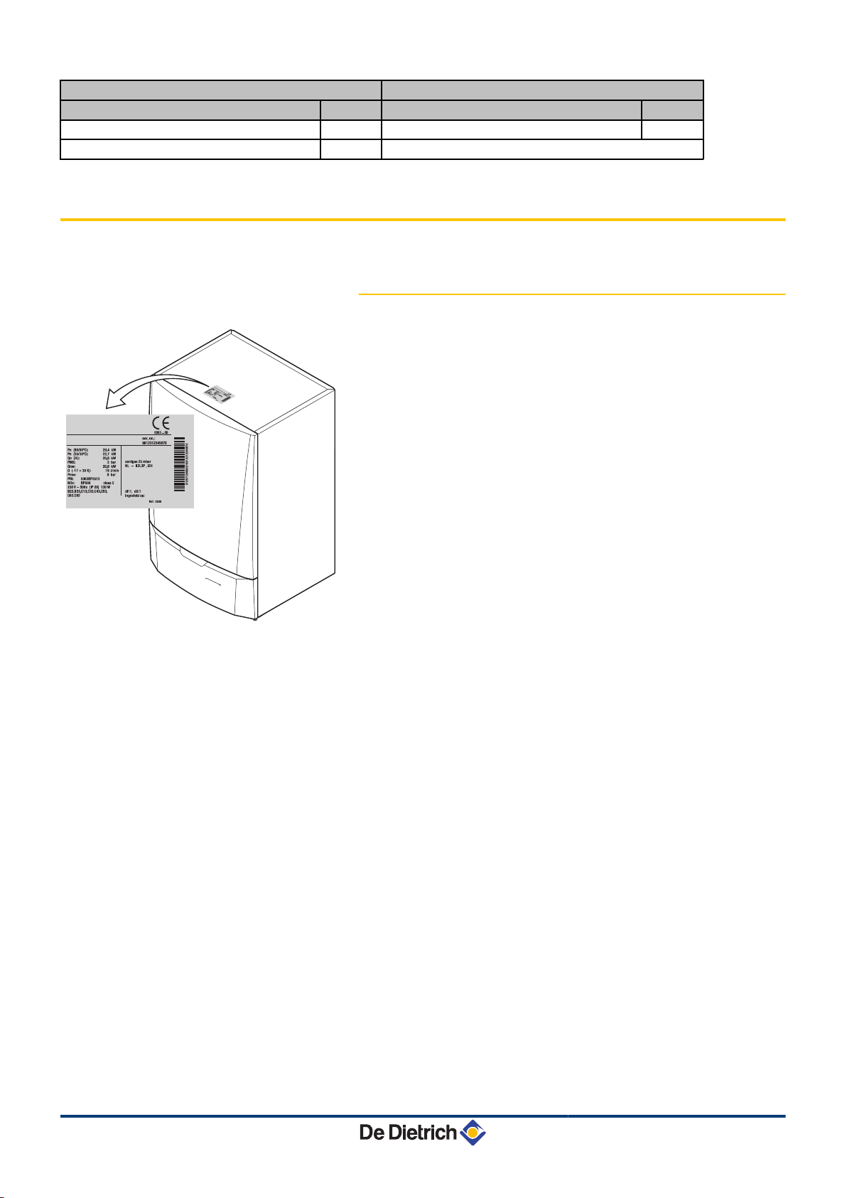
4.3.3. Ventilation
(1)
(2)
If the boiler is installed in a closed box, respect the minimum
dimensions given in the diagram opposite. Also allow openings to
obviate the following hazards:
4 Accumulation of gas
4 Heating of the box
Minimum cross section of the openings: S1 + S2 = 150 cm
Distance between the front of the appliance and the
internal wall of the cupboard.
Distance to allow on either side of the appliance.
2
18
29/04/2010 - 300022146-001-B
Page 21
T001116-B
67
195
265
132
199
266
331
690
450
450
225
140
140
150
257,5
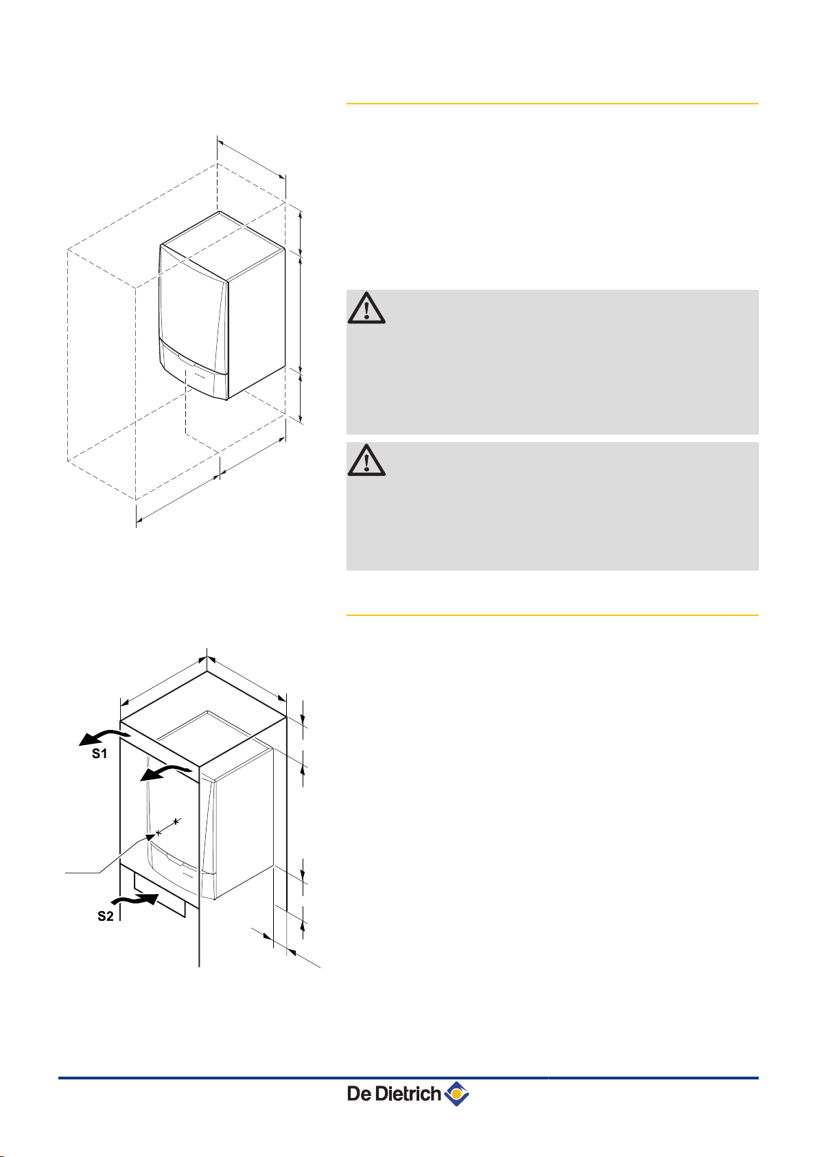
MCA 15 - MCA 25 MCA 25/28 MI 4. Installation
4.3.4. Main dimensions
i
h
ê
j
z
x
Gas /
Gaz
Connection of the combustion gas exhaust pipe Ø 60 mm
Connection of the air intake pipe Ø 100 mm
Safety valve outlet pipe Ø 25 mm
Condensates discharge Ø 25 mm
Heating circuit return G¾"
Domestic cold water inlet G½"
Gas connection G½"
29/04/2010 - 300022146-001-B
y
{
Domestic hot water outlet G½"
Heating circuit flow G¾"
19
Page 22
T001869-A
1
2
3
4
4. Installation MCA 15 - MCA 25 MCA 25/28 MI
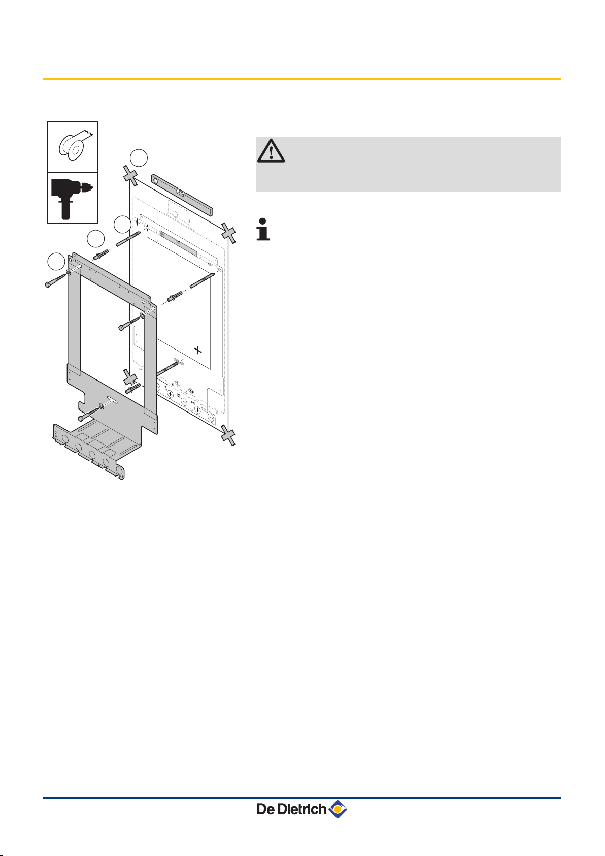
4.4 Installing the mounting frame
The boiler is delivered with a mounting template.
1. Position the mounting template to the wall with adhesive tape.
CAUTION
Using a spirit level, check that the mounting axis is
perfectly horizontal.
2. Drill 3 holes with a Ø of 10 mm.
Additional holes are provided in case one or other of the
standard locating holes prevents the correct location of the
plugs.
3. Put the plugs in place.
4. Secure the mounting frame to the wall using the 3 hexagonal
headed screws provided for this purpose.
20
29/04/2010 - 300022146-001-B
Page 23
T001870-A
T001627-A
T001872-A
MCA 15 - MCA 25 MCA 25/28 MI 4. Installation
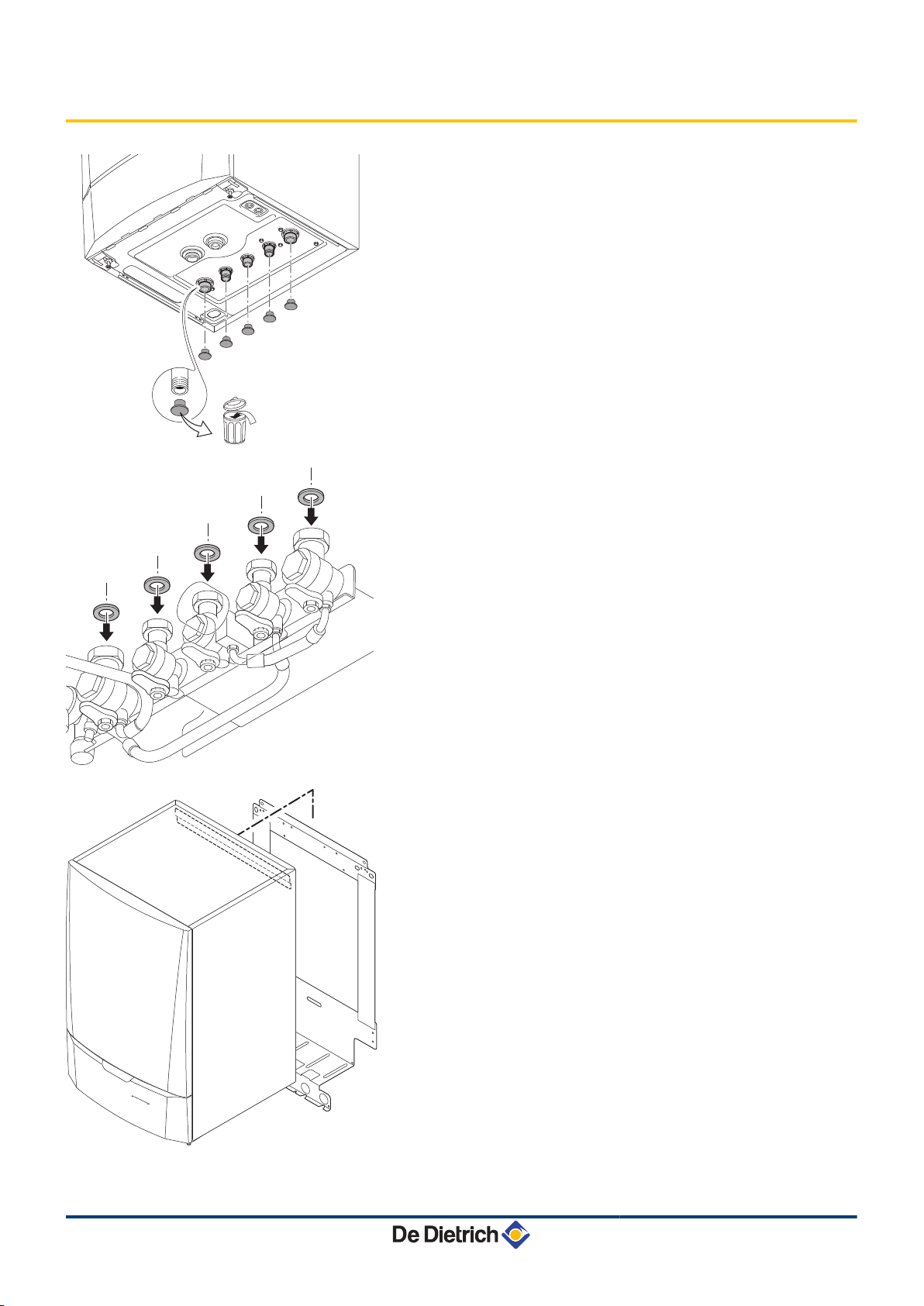
4.5 Positioning the boiler
1. Remove the protective caps from all of the hydraulic inlets and
outlets on the boiler.
2. Fit a fibre gasket to each joint on the valve plate.
29/04/2010 - 300022146-001-B
3. Position the boiler above the plumbing fixtures plate and locate it
against the mounting frame. Gently lower the boiler.
4. Tighten the valve nuts on the boiler.
21
Page 24
T001625-A
4. Installation MCA 15 - MCA 25 MCA 25/28 MI
4.6 Hydraulic connections
4.6.1. Flushing the system
Installation must be carried out in accordance with the prevailing
regulations, the codes of practice and the recommendations in these
instructions.
Installing the boiler in new installations (installations
n
less than 6 months old)
4 Clean the installation with a universal cleaner to eliminate debris
from the appliance (copper, flaxen thread, flux).
4 Thoroughly flush the installation until the water runs clear and
shows no impurities.
Installing the boiler in existing installations
n
4 Remove sludge from the installation.
4 Flush the installation.
4 Clean the installation with a universal cleaner to eliminate debris
from the appliance (copper, flaxen thread, flux).
4 Thoroughly flush the installation until the water runs clear and
shows no impurities.
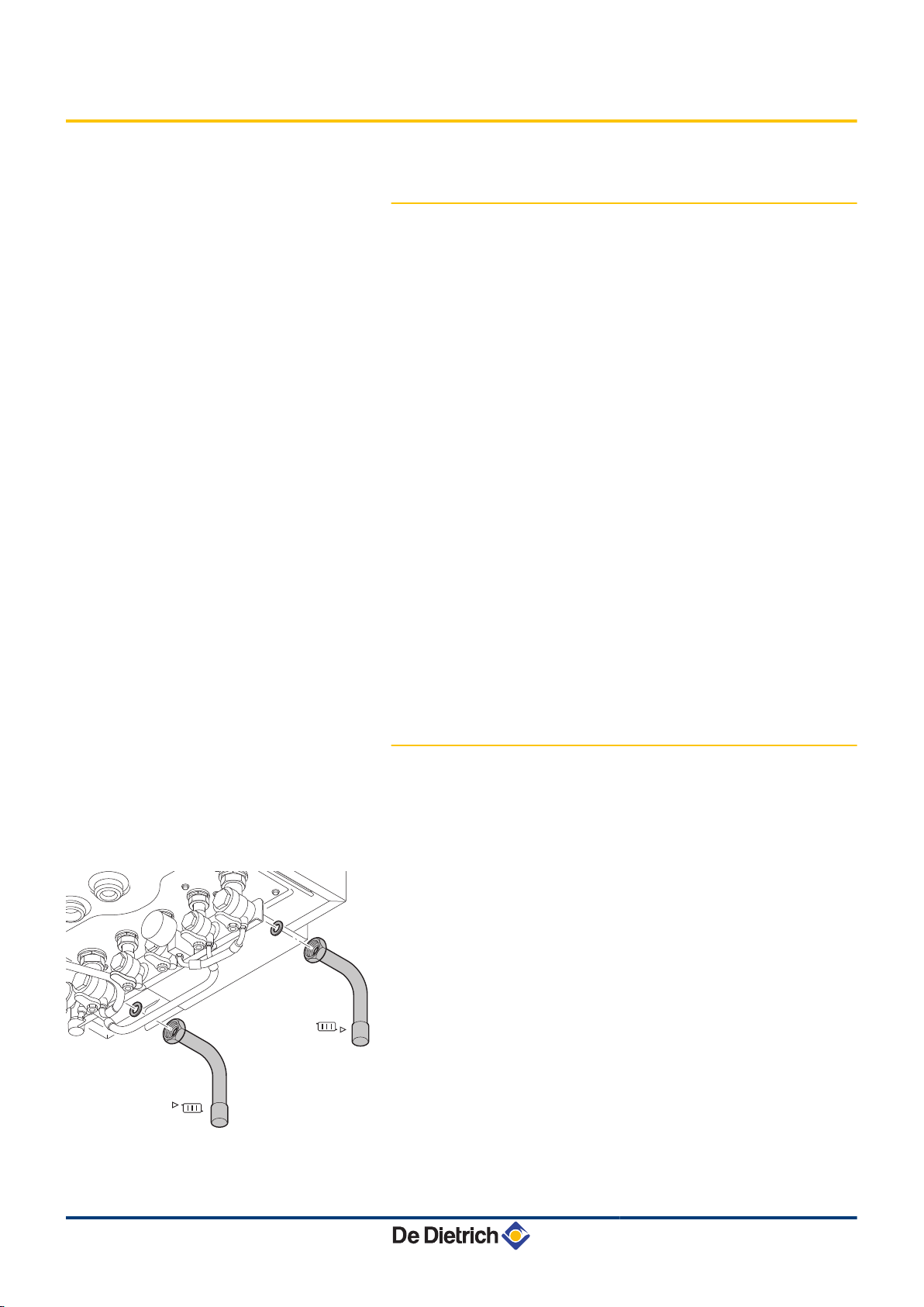
4.6.2. Connection of the heating circuit
1. Connect the heating water outlet pipe to the heating flow
connection.
2. Connect the heating water inlet pipe to the heating return
connection.
{
z
Connection by internal brazing ∅ 22 mm
Connection by internal brazing ∅ 22 mm
22
29/04/2010 - 300022146-001-B
Page 25
T001633-B
T001626-A
MCA 15 - MCA 25 MCA 25/28 MI
4. Installation
4 The boiler is factory fitted with a safety valve mounted
on the left hydrobloc.
CAUTION
4 The heating pipe must be mounted in accordance
with prevailing provisions.
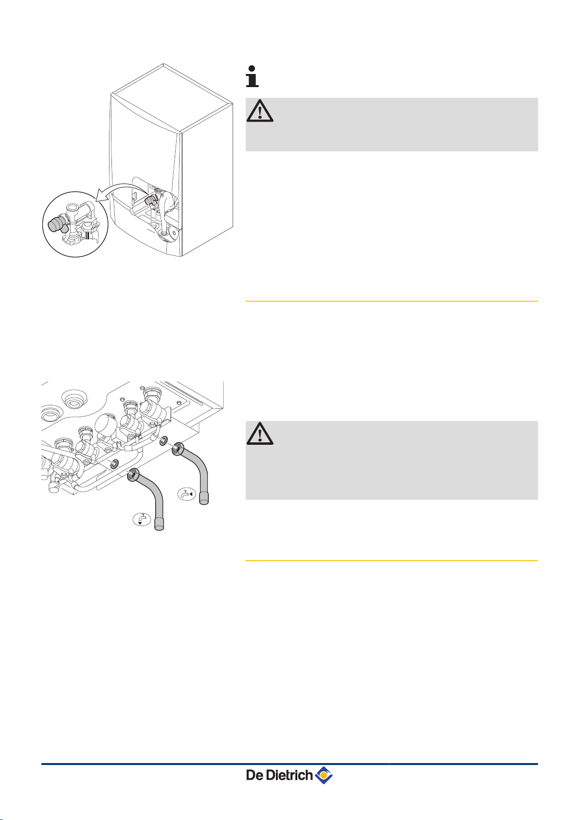
4.6.3. Hydraulic connection of the water circuit
for domestic use
1. Connect the cold water inlet pipe to the domestic cold water
connection.
2. Connect the domestic hot water outlet pipe to the domestic hot
water connection.
x
y
Connection by internal brazing ∅ 16 mm
Connection by internal brazing ∅ 16 mm
CAUTION
4 The domestic water pipes must be connected in
accordance with prevailing provisions.
4 If using synthetic pipes, follow the manufacturer's
(connection) instructions.
4.6.4. Connecting the expansion vessel
The boiler is fitted as standard with an 12-litre expansion vessel.
If the water volume is greater than 150 litres or the static height of the
system exceeds 5 metres, an additional expansion vessel must be
fitted. Refer to the table below to determine the opened expansion
vessel required for the installation.
29/04/2010 - 300022146-001-B
Conditions of validity of the table:
4 3-bar safety valve
4 Average water temperature: 70 °C
Flow temperature: 80 °C
Return temperature: 60 °C
4 The filling pressure in the system is lower than or equal to the initial
pressure in the opened expansion vessel
23
Page 26
T001873-C
T001523-B
4. Installation MCA 15 - MCA 25 MCA 25/28 MI
Initial pressure of the
expansion vessel
0.5 bar 4,8 6,0 7,2 8,4 9,6 12,0 14,4 Volume of the installation x 0,048
1 bar 8,0 10,0
1.5 bar 13,3 16,6 20,0 23,3 26,6 33,3 39,9 Volume of the installation x 0,133
(1) Factory configuration
Volume of the opened expansion vessel depending on the volume of the installation (in litres)
100 125 150 175 200 250 300 > 300
(1)
12,0
14,0 16,0 20,0 24,0 Volume of the installation x 0,080
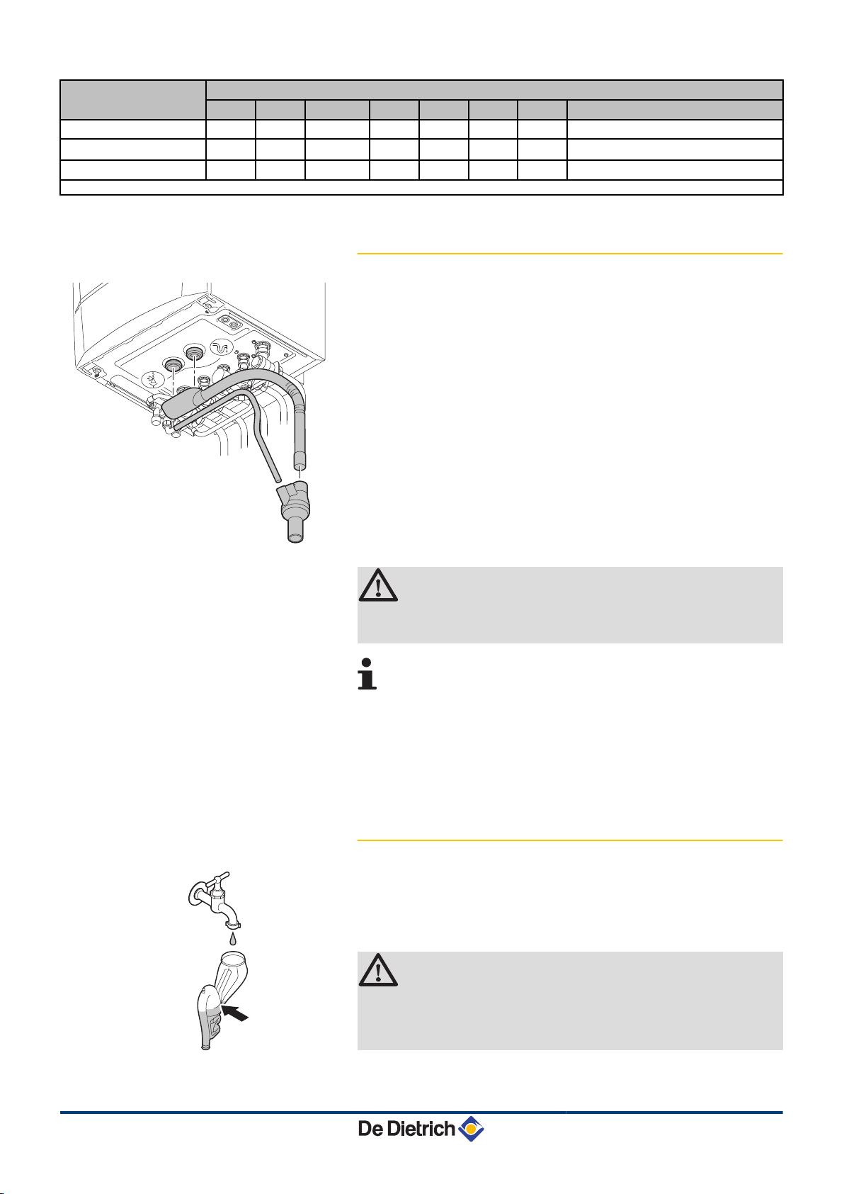
4.6.5. Connecting the condensate discharge pipe
1. Mount a standard drainage pipe, Ø 32 mm or more, leading to the
mains drainage system.
2. Mount the flow collector.
3. Into this, insert the condensate collector hose coming from the
siphon j and the safety valve ê.
4. Into this, insert the discharge hose from the disconnector.
5. Mount a trap or a siphon in the discharge pipe.
CAUTION
Do not make a fixed connection owing to maintenance
work on the siphon.
4 Do not plug the condensate discharge pipe.
4 Set the discharge pipe at a gradient of at least 30
mm per metre, maximum horizontal length 5 metres.
4 Do not drain condensation water into a roof gutter at
any time.
4 Connect the condensate discharge pipe in
accordance with prevailing standards.
4.6.6. Filling the siphon
1. Remove the siphon.
2. Fill the siphon with water. This must be filled up to the level
markers.
3. Re-assemble the siphon.
CAUTION
24
4 Fill the water siphon before starting the boiler to avoid
combustion products escaping from the boiler.
4 Mount the vent hose above the siphon.
29/04/2010 - 300022146-001-B
Page 27
T001621-A
MCA 15 - MCA 25 MCA 25/28 MI 4. Installation
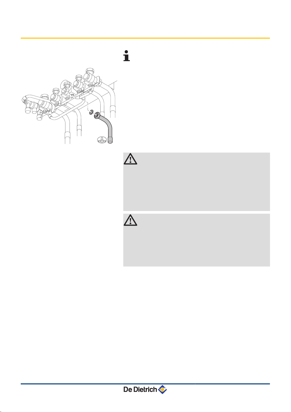
4.7 Gas connection
The diameters of the pipes must be defined in accordance
with the standards in force in your country.
g
Connection by internal brazing ∅ 18 mm
1. Connect the gas inlet pipe.
WARNING
4 Close the main gas valve before starting work on the
gas pipes.
4 Before mounting, check that the gas meter has
sufficient capacity. To do this, you should bear in
mind the consumption of all domestic appliances.
4 If the gas meter has too low a capacity, inform the
energy supply company.
CAUTION
4 Ensure that there is no dust in the gas pipe. Blow into
the pipe or shake it before mounting.
4 We recommend installing a gas filter on the gas pipe
to prevent clogging of the gas valve unit.
4 Connect the gas pipe in accordance with prevailing
standards and regulations.
29/04/2010 - 300022146-001-B
25
Page 28
4
2
6
2
2
1
5
3
12
12
12
L1
L1
Lmax = L1+L2
Lmax =
L
1+L2
Lmax
Lmax
Lmax
Lmax
max
max
max
1m
1m
1m
Lmax
L2
L2
Lmax
Lmax
C
33
C
93
B
23
C
93
C
33
C
33
C
13
C
53
C
43
C
43
C
43
T000275-D
4. Installation MCA 15 - MCA 25 MCA 25/28 MI
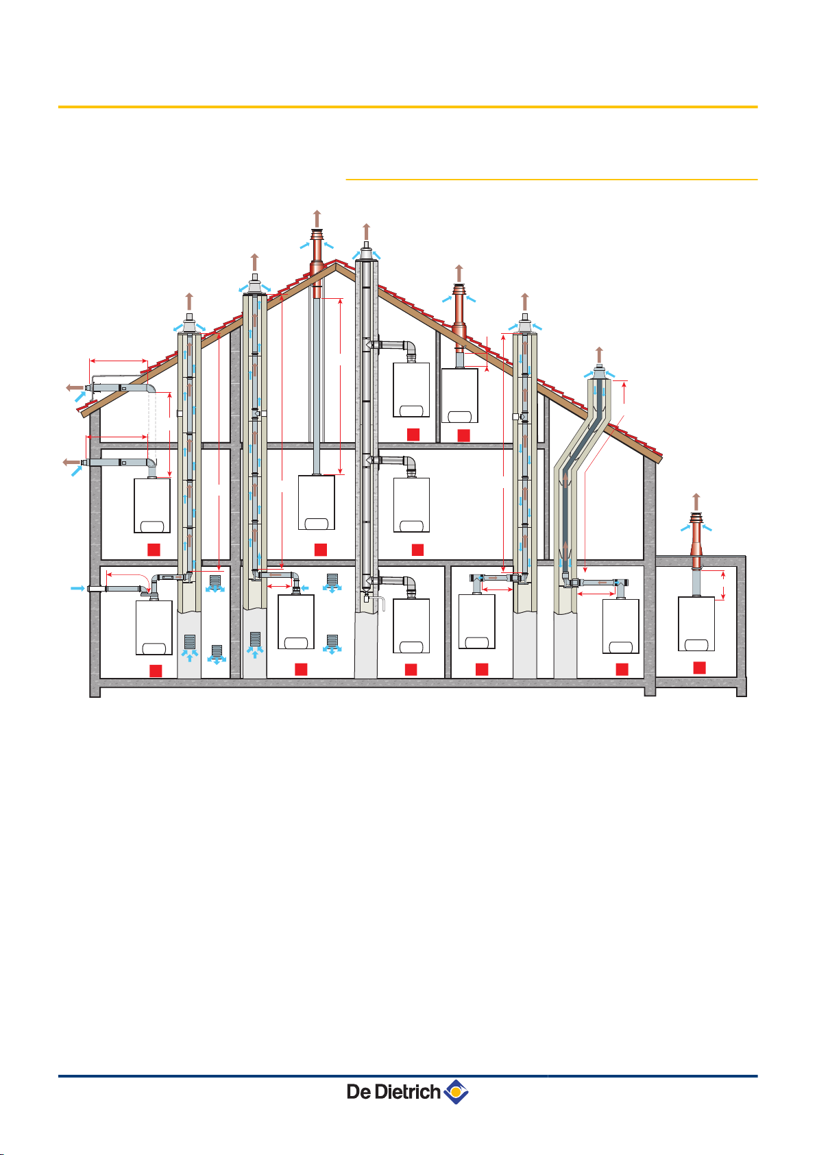
4.8 Flue gas system connections
4.8.1. Classification
26
1
Configuration C
13
Air/flue gas connection by means of concentric pipes to a
horizontal terminal (so-called forced flue)
2
Configuration C
33
Air/flue gas connection by means of concentric pipes to a
vertical terminal (roof outlet)
3
Configuration C
Air/flue gas connection by concentric pipes in the boiler
room and single pipes in the chimney (combustive air in
counter current in the chimney)
93
29/04/2010 - 300022146-001-B
Page 29
MCA 15 - MCA 25 MCA 25/28 MI
4. Installation
4
5
6
12
Configuration C
93
Air/flue gas connection by concentric pipes in the boiler
room and single "flex" in the chimney (combustive air in
counter current in the chimney)
WARNING
4 Only factory components are authorised for
connecting the boiler and the terminal.
4 The clear section must comply with the
standard.
4 The chimney must be swept before the
installation of the evacuation conduit.
Configuration C
53
Air and flue gas connection separated by means of a biflow adapter and single pipes (combustive air taken from
outside)
Configuration B
23
Connection to a chimney using a connection kit
(combustive air taken from the boiler room)
Configuration C
43
Air/flue gas connection to a collective conduit for
watertight boilers (3CE system)
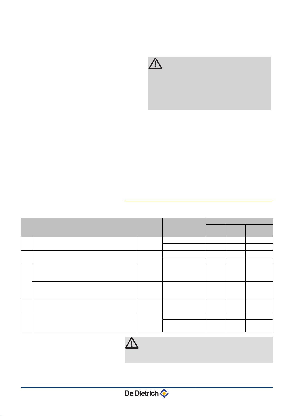
4.8.2. Lengths of the air/flue gas pipes
Type of air/flue gas connection
C13Concentric pipes connected to a horizontal terminal Alu or PPS 60/100 mm 12.0 3.5 4.2
C33Concentric pipes connected to a vertical terminal Alu or PPS 60/100 mm 13.0 4.9 5.5
C93Concentric pipes in the boiler room
Single conduits in the chimney (combustive air in
counter-current)
Concentric pipes in the boiler room
Flexible single conduit in the chimney
C53Bi-flow adapter and separate single air/flue gas ducts
(combustive air taken from outside)
B23Chimney (rigid or flexible duct in furnace flue,
combustive air taken from the premises)
Alu or PPS 60/100 mm
PPS 60/100 mm
Alu 60/100 mm
PPS 80 mm (Rigid duct) 50.0 50.0 50.0
Diameter Maximum length in metres
MCA 15 MCA 25 MCA 25/28
MI
80/125 mm 12.3 23.0 25.7
80/125 mm 10.7 21.0 23.6
15.0 8.1 9.1
60 mm (Rigid duct)
9.9 20.0 22.7
80 mm (Flexible
duct)
50.0 50.0 50.0
2 x 80 mm
80 mm (Flexible
duct)
45.0 45.0 45.0
29/04/2010 - 300022146-001-B
WARNING
Maximum length = lengths of the straight air/flue gas ducts
+ equivalent lengths of other components
For the list of flue gas system accessories and the equivalent lengths,
refer to the current price list.
27
Page 30
8800N001-C
8800N002-C
4. Installation
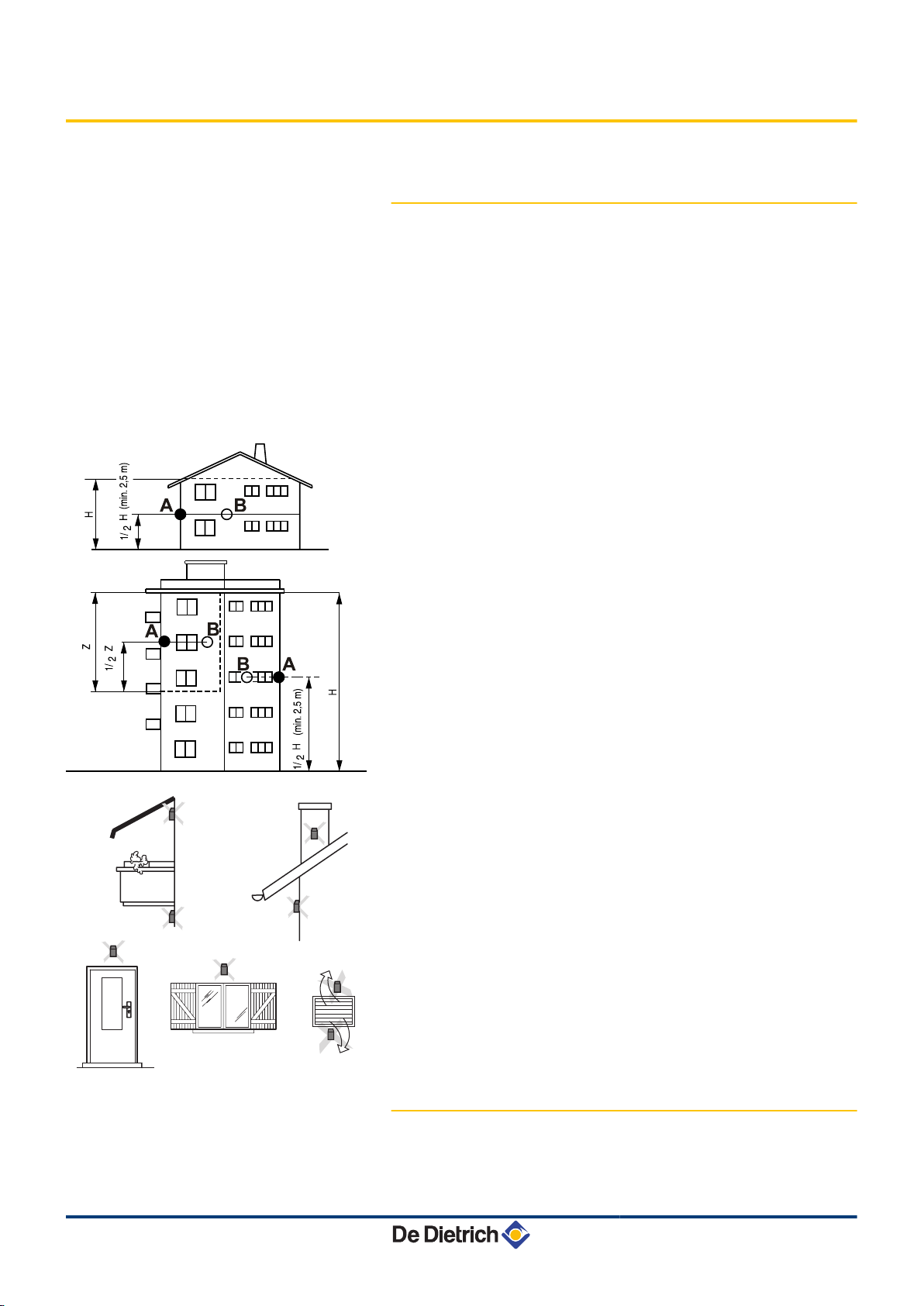
4.9 Installing the outside sensor
4.9.1. Choice of the location
It is important to select a place that allows the sensor to measure the
outside conditions correctly and effectively.
Advised positions:
4 on one face of the area to be heated, on the north if possible
4 half way up the wall in the room to be heated
4 under the influence of meteorological variations
4 protected from direct sunlight
4 easy to access
MCA 15 - MCA 25 MCA 25/28 MI
A
B
H
Z
Recommended position
Possible position
Inhabited height controlled by the sensor
Inhabited area controlled by the sensor
Positions to be avoided:
4 masked by a building element (balcony, roof, etc.)
4 close to a disruptive heat source (sun, chimney, ventilation grid,
etc.)
28
4.9.2. Installing the outside sensor
Mount the sensor using the screws and dowels provided.
29/04/2010 - 300022146-001-B
Page 31

8800N003-B
C002336-E
C
A
B
E
D
MCA 15 - MCA 25 MCA 25/28 MI 4. Installation
4.10 Electrical connections
A
CB wood screws diameter 4 + dowels
4.10.1. Control unit
The boiler is fully pre-wired. The mains supply is made via the cable
C connected to the mains. All other external connections can be made
to the connection connectors (low voltage). The main characteristics
of the control unit are described in the table below.
Power supply voltage 230 VAC/50Hz
Rating of the main fuse F1 (230 VAC) 6.3 AT
Fuse rating F2 (230 VAC) 2 AT
Fan-DC 27 VDC
CAUTION
Keep to the polarity shown on the terminals: phase (L),
neutral (N) and earth *.
A
B
C
D
E
Routing of the 230 V cables
Routing of the sensor cables
Power supply cable
6,3 AT fuse
2 AT fuse
CAUTION
The following components of the appliance are at a
voltage of 230 V:
4 Boiler pump.
4 Combined venturi and gas valve unit.
4 Inverter valve.
4 The majority of components in the control panel and
the terminal box.
4 Power supply cable.
29/04/2010 - 300022146-001-B
29
Page 32

4. Installation MCA 15 - MCA 25 MCA 25/28 MI
4.10.2. Recommendations
WARNING
4 Only qualified professionnals may carry out electrical
connections, always with the power off.
4 The boiler is entirely pre-wired. Do not modify the
connections inside the control panel.
4 Earth the appliance before making any electrical
connections.
Make the electrical connections of the appliance according to:
4 the instructions of the prevailing standards.
4 the instructions on the circuit diagrams provided with the
appliance.
4 the recommendations in the instructions.
CAUTION
4 Separate the sensor cables from the 230 V cables.
4 Outside the boiler: Use 2 pipes or cable guides at
least 10 cm apart.
30
29/04/2010 - 300022146-001-B
Page 33

PCU
SU
PSU
On/off
OT BL RL Tout Tdhw
2
3
1
TS + B AB
0-10V
S AMB C
4 3 2 1 2 1
+ -
S AMB B
2 1
S AMB A
2 1
S SYST + TA -
S ECS S EXT S DEP C
2 12 12 12 1 2 1
S DEP B
2 1
TS + C AUXC
SCU
SCU
PCU
C002299-F
MCA 15 - MCA 25 MCA 25/28 MI 4. Installation
4.10.3. Position of the PCBs
A
Z
E
Do not connect anything to the terminal block.
Optional PCB (Package AD249)
Do not connect anything to the terminal block.
29/04/2010 - 300022146-001-B
31
Page 34

C002325-C
2
1
C002326-B
4
3
3
4. Installation MCA 15 - MCA 25 MCA 25/28 MI
4.10.4. Accessing the connection terminal blocks
To access the connection terminal blocks, proceed as follows:
1. Unscrew the 2 screws under the front panel by a quarter turn.
2. Remove the front panel.
3. Open the holding clips located on the sides.
4. Tilt the control panel forward.
32
29/04/2010 - 300022146-001-B
Page 35

C002327-B
5
6
6
C002330-C
7
MCA 15 - MCA 25 MCA 25/28 MI 4. Installation
5. Lift the clip located in front of the control panel.
6. Lift the control panel cover.
7. Unclip the PCB cover.
29/04/2010 - 300022146-001-B
33
Page 36

C002304-M
2
3
On/off
OT BL RL Tout Tdhw
1
TS + B AB
0-10V
S AMB C
4 3 2 1 2 1
+ -
S AMB B
2 1
S AMB A
2 1
S SYST + TA -
S ECS S EXT S DEP C
2 12 12 12 1 2 1
S DEP B
2 1
SCU PCU
4
4. Installation MCA 15 - MCA 25 MCA 25/28 MI
4.10.5. Connecting a direct heating circuit
A
Z
E
Do not connect anything to the terminal block.
Connect the outside temperature sensor.
Connect a safety thermostat if the heating circuit is for
underfloor heating.
4 Remove the bridge.
4 Connect the wires from the safety thermostat to the
connector.
Settings to be made for this type of installation
Parameters Access Settings to be made See chapter
INSTALLATION
If safety thermostat is connected to
BL on the connection terminal
block:
"Installer" level
#SYSTEM menu
"Installer" level
#PRIMARY INSTAL.P
menu
R
IN.BL
Do not connect anything to the terminal block.
EXTENDED
STOP HEAT
¼ "Displaying the parameters
in extended mode", page 71
¼ ""Professional" settings",
page 82
34
29/04/2010 - 300022146-001-B
Page 37

C002305-j
3
4
5
6
7
8
On/off
OT BL RL Tout Tdhw
1 2
TS + B AB
0-10V
S AMB C
4 3 2 1 2 1
+ -
S AMB B
2 1
S AMB A
2 1
S SYST + TA -
S ECS S EXT S DEP C
2 12 12 12 1 2 1
S DEP B
2 1
SCU PCU
MCA 15 - MCA 25 MCA 25/28 MI 4. Installation
4.10.6. Connecting a direct heating circuit and a
domestic hot water tank
A
Z
E
R
Do not connect anything to the terminal block.
CAUTION
Do not connect anything to the Mr outlet on the
terminal block. The reversal valve is connected
to the PCU PCB in the boiler.
Connect the outside temperature sensor.
Connect a safety thermostat if the heating circuit is for
underfloor heating.
4 Remove the bridge.
4 Connect the wires from the safety thermostat to the
connector.
29/04/2010 - 300022146-001-B
35
Page 38

4. Installation MCA 15 - MCA 25 MCA 25/28 MI
T
Connect the DHW tank anode.
CAUTION
4 If the tank is fitted with a Titan Active
System® impressed current anode,
connect the anode to the inlet (+ on the
anode, - on the tank).
4 If the tank is not fitted with an impressed
current anode, put the simulation
connector in place (delivered with the DHW
sensor - package AD212).
Y
U
Connect the DHW sensor (Package AD212).
Connect the domestic hot water looping pump
(Optional).
I
Settings to be made for this type of installation
Parameters Access Settings to be made See chapter
INSTALLATION
If a domestic hot water looping pump
is connected to MA on the terminal
block:
O.PUMP A
If safety thermostat is connected to
BL on the connection terminal block:
IN.BL
(1) The parameter is only displayed if INSTALLATION parameter is set to EXTENDED
(1)
"Installer" level
#SYSTEM menu
"Installer" level
#SYSTEM menu
"Installer" level
#PRIMARY INSTAL.P
menu
Do not connect anything to the terminal block.
EXTENDED
¼ "Displaying the parameters
in extended mode", page 71
DHW LOOP
¼ "Setting the parameters
specific to the installation", page
72
TOTAL STOP
¼ ""Professional" settings",
page 82
36
29/04/2010 - 300022146-001-B
Page 39

C002367-F
3
6
9
10
11
7
8
1 2
4
5
13
12
On/off
OT BL RL Tout Tdhw
TS + B AB
0-10V
S AMB C
4 3 2 1 2 1
+ -
S AMB B
2 1
S AMB A
2 1
S SYST + TA -
S ECS S EXT S DEP C
2 12 12 12 1 2 1
S DEP B
2 1
TS + C AUXC
SCU PCU
MCA 15 - MCA 25 MCA 25/28 MI 4. Installation
4.10.7. Connecting two circuits and a domestic hot
water tank before the mixing tank
A
Z
E
R
Do not connect anything to the terminal block.
CAUTION
Do not connect anything to the Mr outlet on the
terminal block. The reversal valve is connected
to the PCU PCB in the boiler.
Connect the outside temperature sensor.
Connect a safety thermostat if the heating circuit is for
underfloor heating.
29/04/2010 - 300022146-001-B
4 Remove the bridge.
4 Connect the wires from the safety thermostat to the
connector.
T
Connecting an additional circuit to the AD249 option.
37
Page 40

4. Installation MCA 15 - MCA 25 MCA 25/28 MI
Y
U
I
O
P
a
z
Connect the heating pump (circuit A).
If underfloor heating is being used, put a safety
thermostat in place after the heating pump. The
safety thermostat will shut down the heating
pump in the event of overheating.
Low loss header.
Connect the DHW tank anode.
CAUTION
4 If the tank is fitted with a Titan Active
System® impressed current anode,
connect the anode to the inlet (+ on the
anode, - on the tank).
4 If the tank is not fitted with an impressed
current anode, put the simulation
connector in place (delivered with the DHW
sensor - package AD212).
Connect the heating pump (circuit B).
Connect the 3-way valve (circuit B).
Connect the DHW sensor (Package AD212).
Connect the domestic hot water looping pump to the
AUX outlet on the AD249 option
e
Do not connect anything to the terminal block.
38
29/04/2010 - 300022146-001-B
Page 41

C002293-j
4
6
8
9
11
10
2
7
1
3
5
12
On/off
OT BL RL Tout Tdhw
TS + B AB
0-10V
S AMB C
4 3 2 1 2 1
+ -
S AMB B
2 1
S AMB A
2 1
S SYST + TA -
S ECS S EXT S DEP C
2 12 12 12 1 2 1
S DEP B
2 1
TS + C AUXC
SCU PCU
MCA 15 - MCA 25 MCA 25/28 MI 4. Installation
4.10.8. Connecting two circuits and a domestic hot
water tank after the mixing tank
A
Z
E
R
T
Do not connect anything to the terminal block.
Connect the outside temperature sensor.
Connect a safety thermostat if the heating circuit is for
underfloor heating.
4 Remove the bridge.
4 Connect the wires from the safety thermostat to the
connector.
Low loss header
Connecting an additional circuit to the AD249 option.
29/04/2010 - 300022146-001-B
39
Page 42

4. Installation MCA 15 - MCA 25 MCA 25/28 MI
Y
U
I
O
P
a
Connect the heating pump (circuit A).
If underfloor heating is being used, put a safety
thermostat in place after the heating pump. The
safety thermostat will shut down the heating
pump in the event of overheating.
Connect the DHW tank anode.
CAUTION
4 If the tank is fitted with a Titan Active
System® impressed current anode,
connect the anode to the inlet (+ on the
anode, - on the tank).
4 If the tank is not fitted with an impressed
current anode, put the simulation
connector in place (delivered with the DHW
sensor - package AD212).
Connect the heating pump (circuit B).
Connect the 3-way valve (circuit B).
Connect the DHW sensor (Package AD212).
Connect the domestic hot water looping pump to the
MAUX outlet on the AD249 option.
z
Settings to be made for this type of installation
Parameters Access Settings to be made See chapter
INSTALLATION
O.DHW:
(1) The parameter is only displayed if INSTALLATION parameter is set to EXTENDED
(1)
"Installer" level
#SYSTEM menu
"Installer" level
#SYSTEM menu
EXTENDED
PUMP
Do not connect anything to the terminal block.
¼ "Displaying the parameters in extended mode", page
71
¼ "Setting the parameters specific to the installation",
page 72
40
29/04/2010 - 300022146-001-B
Page 43

C002368-H
On/off
OT BL RL Tout Tdhw
TS + B AB
0-10V
S AMB C
4 3 2 1 2 1
+ -
S AMB B
2 1
S AMB A
2 1
S SYST + TA -
S ECS S EXT S DEP C
2 12 12 12 1 2 1
S DEP B
2 1
SCU PCU
4
5
6
8
7
3
2
1
9
M
MCA 15 - MCA 25 MCA 25/28 MI 4. Installation
4.10.9. Hot water storage tank connection
QUADRO DU 750 storage tank
n
In this installation example, the storage tank (type QUADRO DU
750) incorporates a domestic hot water zone. The boiler starts up
systematically to maintain the domestic hot water zone in the storage
tank or to maintain the independent tank at temperature.
If the storage tank does not have a DHW zone, use an
independent domestic hot water tank.
A
Z
E
Do not connect anything to the terminal block.
Connect the heating pump (Circuit A).
Connect the DHW tank anode.
If the tank is not fitted with an impressed current
anode, put the simulation connector in place
(delivered with the DHW sensor - package
AD212).
R
T
Connect the DHW sensor (Package AD212).
Connect the sensor from the storage tank (Package
AD250).
29/04/2010 - 300022146-001-B
41
Page 44

4. Installation MCA 15 - MCA 25 MCA 25/28 MI
Y
U
I
O
Settings to be made for this type of installation
Parameters Access Settings to be made See chapter
INSTALLATION
(1)
I.SYST
(1) The parameter is only displayed if INSTALLATION parameter is set to EXTENDED
"Installer" level
#SYSTEM menu
"Installer" level
#SYSTEM menu
EXTENDED
STORAGE TANK
Buffer tank.
Solar sensor probe.
Connect the solar station to the solar collectors.
Do not connect anything to the terminal block.
¼ "Displaying the parameters in extended mode", page
71
¼ "Setting the parameters specific to the installation",
page 72
The DHW part is maintained at the DHW set point by the
boiler.
The heating zone is maintained at the set temperature
calculated according to the outside temperature. The zone
is reheated when the heating buffer temperature sensor
T falls -6°C below the calculated set temperature.
Reheating in the heating zone stops when the heating
buffer temperature rises above the calculated set
temperature.
42
29/04/2010 - 300022146-001-B
Page 45

2
10
G000030A
9
On/off
OT BL RL Tout Tdhw
TS + B AB
0-10V
S AMB C
4 3 2 1 2 1
+ -
S AMB B
2 1
S AMB A
2 1
S SYST + TA -
S ECS S EXT S DEP C
2 12 12 12 1 2 1
S DEP B
2 1
SCU PCU
1
3
5
7
6
8
M
4
MCA 15 - MCA 25 MCA 25/28 MI 4. Installation
PS storage tank and DHW tank connected to the boiler
n
The boiler only starts up if the storage tank is not hot enough to
guarantee loading of the DHW tank.
A Connect a domestic hot water tank if the storage tank R
is only used for heating
Z
E
R
Connect the DHW sensor (Package AD212).
Connect the heating pump (Circuit A).
Buffer tank.
T
Y
U
Connect the sensor from the storage tank.
Solar sensor probe.
Connect the solar station to the solar collectors.
29/04/2010 - 300022146-001-B
43
Page 46

4. Installation MCA 15 - MCA 25 MCA 25/28 MI
I
Connect the DHW tank anode.
If the tank is not fitted with an impressed current
anode, put the simulation connector in place
(delivered with the DHW sensor - package
AD212).
O
Settings to be made for this type of installation
Parameters Access Settings to be made See chapter
INSTALLATION
(1)
I.SYST
O.DHW:
(1) The parameter is only displayed if INSTALLATION parameter is set to EXTENDED
(1)
"Installer" level
#SYSTEM menu
"Installer" level
#SYSTEM menu
"Installer" level
#SYSTEM menu
EXTENDED
STORAGE TANK
PUMP
Do not connect anything to the terminal block.
¼ "Displaying the parameters in extended mode", page
71
¼ "Setting the parameters specific to the installation",
page 72
The DHW part is maintained at the DHW set point by the
boiler.
The heating zone is maintained at the set temperature
calculated according to the outside temperature. The zone
is reheated when the heating buffer temperature sensor
falls -6°C below the calculated set temperature. Reheating
in the heating zone stops when the heating buffer
temperature rises above the calculated set temperature.
PS storage tank and DHW tank connected to the storage
n
tank
The boiler only starts up production of domestic hot water if the
storage tank is not hot enough to guarantee tank loading.
44
29/04/2010 - 300022146-001-B
Page 47

C002369-F
3
6
5
2
1
4
8
7
On/off
OT BL RL Tout Tdhw
TS + B AB
0-10V
S AMB C
4 3 2 1 2 1
+ -
S AMB B
2 1
S AMB A
2 1
S SYST + TA -
S ECS S EXT S DEP C
2 12 12 12 1 2 1
S DEP B
2 1
SCU PCU
MCA 15 - MCA 25 MCA 25/28 MI 4. Installation
A
Z
E
R
T
Y
U
Do not connect anything to the terminal block.
Connect the heating pump (Circuit A).
Connect the DHW tank anode.
If the tank is not fitted with an impressed current
anode, put the simulation connector in place
(delivered with the DHW sensor - package
AD212).
Buffer tank.
Solar sensor probe.
Connect the solar station to the solar collectors.
Domestic hot water boiler.
Connect the DHW sensor.
I
Do not connect anything to the terminal block.
29/04/2010 - 300022146-001-B
45
Page 48

C002298-i
1
3
5
2
6
On/off
OT BL RL Tout Tdhw
TS + B AB
0-10V
S AMB C
4 3 2 1 2 1
+ -
S AMB B
2 1
S AMB A
2 1
S SYST + TA -
S ECS S EXT S DEP C
2 12 12 12 1 2 1
S DEP B
2 1
SCU PCU
4
4. Installation MCA 15 - MCA 25 MCA 25/28 MI
Settings to be made for this type of installation
Parameters Access Settings to be made See chapter
INSTALLATION
(1)
I.SYST
O.DHW:
(1)
"Installer" level
#SYSTEM menu
"Installer" level
#SYSTEM menu
"Installer" level
EXTENDED
ST.TANK+DHW
PUMP
¼ "Displaying the parameters in extended mode", page
71
¼ "Setting the parameters specific to the installation",
page 72
#SYSTEM menu
(1) The parameter is only displayed if INSTALLATION parameter is set to EXTENDED
The DHW tank is loaded from the storage tank. If, during
DHW loading, the temperature of the storage tank falls
below the primary DHW set point (parameter
PRIM.TEMP.DHW), the boiler maintains the latter at
temperature to guarantee the loading of the DHW tank
The heating zone is maintained at the set temperature
calculated according to the outside temperature. The zone
is reheated when the heating buffer temperature sensor
falls -6°C below the calculated set temperature. Reheating
in the heating zone stops when the heating buffer
temperature rises above the calculated set temperature.
4.10.10. Pool connection
46
A
Z
E
Connect the secondary swimming pool pump.
Connect the swimming pool sensor.
Plate heat exchanger.
29/04/2010 - 300022146-001-B
Page 49

MCA 15 - MCA 25 MCA 25/28 MI 4. Installation
R
Pool heating cut-off control
When the parameter I.TEL: is on 0/1 B, the
swimming pool is no longer heated when the
contact is open (factory setting), only the
antifreeze continues to be active.
The contact direction can still be adjusted by the
parameter CT.TEL.
T
Y
Settings to be made for this type of installation
Parameters Access Settings to be made See chapter
INSTALLATION
CIRC. B:
If I.TEL: is used
I.TEL:
MAX. CIRC. B
"Installer" level
#SYSTEM menu
"Installer" level
#SYSTEM menu
"Installer" level
#SYSTEM menu
"Installer" level
#SECONDARY LIMITS menu
EXTENDED
SWIM.P.
0/1 B
Set the value of MAX.CIRC.B to
the temperature corresponding
to the needs of the exchanger
Connect the primary swimming pool pump.
Do not connect anything to the terminal block.
¼ "Displaying the parameters in
extended mode", page 71
¼ "Setting the parameters specific
to the installation", page 72
¼ ""Professional" settings", page
82
Controlling the pool circuit
n
The control system can be used to manage a swimming pool circuit
in both cases:
Case 1: The control system regulates the primary circuit (boiler/
exchanger) and the secondary circuit (exchanger/pool).
4 Connect the primary circuit pump (boiler/exchanger) to the MB
outlet on the connection terminal block. The temperature
MAX.CIRC.B is then guaranteed during comfort periods on
programme B in summer and winter alike.
4 Connect the swimming pool sensor (package AD212) to the S
DEP B inlet on the connection terminal block.
4 Set the set point of the pool sensor using key C in the range 5 -
39°C.
Case 2: The pool has already a regulation system that is to be
kept. The control system only regulates the primary circuit
(boiler/exchanger).
4 Connect the primary circuit pump (boiler/exchanger) to the MB
outlet on the connection terminal block.
The temperature MAX.CIRC.B is then guaranteed during comfort
periods on programme B in summer and winter alike.
29/04/2010 - 300022146-001-B
The swimming pool can also be connected to circuit C by
adding the AD249 option:
4 Make the connection to the terminal blocks marked
C.
4 Set the parameters for circuit C.
47
Page 50

C002432-E
6
7
1
2
3
4
8
5
On/off
OT BL RL Tout Tdhw
TS + B AB
0-10V
S AMB C
4 3 2 1 2 1
+ -
S AMB B
2 1
S AMB A
2 1
S SYST + TA -
S ECS S EXT S DEP C
2 12 12 12 1 2 1
S DEP B
2 1
TS + C AUXC
SCU PCU
4. Installation MCA 15 - MCA 25 MCA 25/28 MI
Hourly programming of the secondary circuit pump
n
The secondary pump operates during programme B comfort periods
in summer and winter alike.
Stopping
n
To prepare your pool for winter, consult your pool specialist.
4.10.11. Connecting a mixed tank
A
Z
E
Do not connect anything to the terminal block.
Option of connecting the electric tank (with AD249
option)
or to E
Outlet circuit A - Option of connecting the electric tank (or
to Z)
48
R
Power control relay to the electrical resistor
29/04/2010 - 300022146-001-B
Page 51

C002294-F
V
PRG
TELCOM 2
ALP
AL2
AL1
3
2
1
SET
#09
V
8
7
65
4321
7
1
5
9
On/off
OT BL RL Tout Tdhw
TS + B AB
0-10V
S AMB C
4 3 2 1 2 1
+ -
S AMB B
2 1
S AMB A
2 1
S SYST + TA -
S ECS S EXT S DEP C
2 12 12 12 1 2 1
S DEP B
2 1
TS + C AUXC
SCU PCU
3
4
2
8
6
MODE
r
x
0 2 4 6 8 10 12 14 16 18 22 2420
c
MODE
r
x
0 2 4 6 8 10 12 14 16 18 22 2420
c
MCA 15 - MCA 25 MCA 25/28 MI 4. Installation
T
Connect the DHW tank anode.
If the tank is not fitted with an impressed current
anode, put the simulation connector in place
(delivered with the DHW sensor - package
AD212).
Y
U
I
Settings to be made for this type of installation
Parameters Access Settings to be made See chapter
INSTALLATION
If the electric tank is connected to MA:
CIRC. A:
(1)
If the electric tank is connected to
MAUX:
S.AUX:
(1) The parameter is only displayed if INSTALLATION parameter is set to EXTENDED
(1)
"Installer" level
#SYSTEM menu
"Installer" level
#SYSTEM menu
"Installer" level
#SYSTEM menu
Connect the DHW sensor (Package AD212).
Connect the outside temperature sensor
Do not connect anything to the terminal block.
EXTENDED
¼ "Displaying the parameters in
extended mode", page 71
DHW ELEC
¼ "Setting the parameters specific
to the installation", page 72
DHW ELEC
4.10.12. Connecting the options
For example: TELCOM remote vocal monitoring module, remote
controls for circuits A and B, second DHW tank
29/04/2010 - 300022146-001-B
49
Page 52

4
7
8
5
32
6
1
C002435-C
4. Installation MCA 15 - MCA 25 MCA 25/28 MI
A
Z
E
R
T
Y
Do not connect anything to the terminal block.
Connect the load pump to the second tank.
Second domestic hot water tank
Connect the DHW sensor from the second tank.
Alarm indicator
Connect the TELCOM remote vocal monitoring module
(depending on its availability in your country).
U
I
O
Settings to be made for this type of installation
Parameters Access Settings to be made See chapter
INSTALLATION
O.PUMP A
If second tank connected:
S.AUX:
(1) The parameter is only displayed if INSTALLATION parameter is set to EXTENDED
(1)
(1)
"Installer" level
#SYSTEM menu
"Installer" level
#SYSTEM menu
"Installer" level
#SYSTEM menu
EXTENDED
FAILURE
DHW
Connecting the BUS cascade, VM
Connect the remote control (Package AD254/FM52).
Do not connect anything to the terminal block.
¼ "Displaying the parameters in extended
mode", page 71
¼ "Setting the parameters specific to the
installation", page 72
4.10.13. Connection in cascade
DHW tank after the mixing tank
n
A
Z
50
Master boiler
Secondary boiler
29/04/2010 - 300022146-001-B
Page 53

MCA 15 - MCA 25 MCA 25/28 MI 4. Installation
E
R
T
Y
U
I
Secondary boiler
D.H.W. load pump
Connect the DHW sensor (Package AD212)
Cable BUS
Low loss header
Cascade outlet sensor
Connect the sensor to the terminal block S SYST on the
master boiler.
Settings to be made for this type of installation: Master boiler
Parameters Access Settings to be made See chapter
INSTALLATION
O.DHW:
CASCADE:
MASTER
CONTROLLER
SYSTEM NETWORK
(1) The parameter is only displayed if INSTALLATION parameter is set to EXTENDED
(1)
(1)
(1)
"Installer" level
#SYSTEM menu
"Installer" level
#SYSTEM menu
"Installer" level
#NETWORK menu
"Installer" level
#SYSTEM menu
(1)
"Installer" level
#SYSTEM menu
EXTENDED
PUMP
ON
ON
ADD SLAVE
¼ "Displaying the parameters in extended
mode", page 71
¼ "Setting the parameters specific to the
installation", page 72
¼ "Configuring the network", page 88
Settings to be made for this type of installation: Follower boilers
Parameters Access Settings to be made See chapter
INSTALLATION
CASCADE:
MASTER
CONTROLLER
SLAVE NUMBER
(1) The parameter is only displayed if INSTALLATION parameter is set to EXTENDED
(1)
(1)
(1)
"Installer" level
#SYSTEM menu
"Installer" level
#NETWORK menu
"Installer" level
#SYSTEM menu
"Installer" level
#SYSTEM menu
EXTENDED
ON
OFF
2, 3, ...
¼ "Displaying the parameters in extended
mode", page 71
¼ "Configuring the network", page 88
29/04/2010 - 300022146-001-B
51
Page 54

4
3
5
2
6
7
1
C002591-B
4. Installation MCA 15 - MCA 25 MCA 25/28 MI
DHW tank on master boiler
n
A
Z
E
R
T
Y
Connect the DHW sensor (Package AD212)
Master boiler
Secondary boiler
Secondary boiler
Low loss header
Cascade outlet sensor
Connect the sensor to the terminal block S SYST on the
master boiler.
Settings to be made for this type of installation: Master boiler
Parameters Access Settings to be made See chapter
INSTALLATION
O.DHW:
CASCADE:
MASTER
CONTROLLER
SYSTEM NETWORK
(1) The parameter is only displayed if INSTALLATION parameter is set to EXTENDED
(1)
(1)
(1)
"Installer" level
#SYSTEM menu
"Installer" level
#SYSTEM menu
"Installer" level
#NETWORK menu
"Installer" level
#SYSTEM menu
(1)
"Installer" level
#SYSTEM menu
EXTENDED
RV
ON
ON
ADD SLAVE
¼ "Displaying the parameters in extended
mode", page 71
¼ "Setting the parameters specific to the
installation", page 72
¼ "Configuring the network", page 88
Settings to be made for this type of installation: Follower boilers
Parameters Access Settings to be made See chapter
INSTALLATION
CASCADE:
MASTER
CONTROLLER
SLAVE NUMBER
(1) The parameter is only displayed if INSTALLATION parameter is set to EXTENDED
(1)
(1)
(1)
"Installer" level
#SYSTEM menu
"Installer" level
#NETWORK menu
"Installer" level
#SYSTEM menu
"Installer" level
#SYSTEM menu
EXTENDED
ON
OFF
2, 3, ...
¼ "Displaying the parameters in extended
mode", page 71
¼ "Configuring the network", page 88
52
29/04/2010 - 300022146-001-B
Page 55

T001871-H
2 31
K1
X1
X14
X13
X12
X3
X2
X4
X5
X6
X7
X8
X9
X10
X11
HLS
1 2 7 8 9 10
X12
3 4 5 6
X6
1 2 3
GN/
YW
WH
BL
GB
153
X21
X8
1 2 3
PUMP A
BR
BL
GN/
YW
3 1 2
X41
SCU-C
X11
1 2 3 4 5 6
WHGYRD
GN
YWOR
DV
X7
1 2 3
WH
BK
RD
1 3 2
X121
IT
X5
2 3 4 1
E
BK
BL
GN/
YW
GY
1 23
X22
PWM
PUMP
12 13
BK
BK
1 2
X116
FTSRTS
9
RD
1
BK
1
2 2
X115
8
BL
1
22
X114
PS
10 11
BK
BK
3 1
X112
FS
2 3
BK
BK
1 3
X113
X10
4 5 7 6
X111
BK
BK
BK
BK
1 2 3 4
PSU
X9
2 3 4 5
X91
BK
BK
BK
BK
1 2 4 5
FAN
1
BK
BK
1
2
X117
P
230V, 50Hz
L N
SCU-C
X2
1 32
BL
BR
GN/
YW
X1
1 23
BR
BL
GN/YW
X3
4 3 2 15
BR
BL
BR
BL
GN/
YW
3 1
4 2
X51
S
DIS
MCA 15 - MCA 25 MCA 25/28 MI 4. Installation
4.11 Electrical diagram
P
SCU-C
S
IT
E
GB
29/04/2010 - 300022146-001-B
Power supply
control panel PCB
On/Off switch
Ignition transformer
Ignition power relay
Combined venturi and gas valve
unit
DV
PUMP A
HLS
FAN
FS
RTS
Inverter valve
Modulating control on the
boiler pump
Safety thermostat
Fan
Flowmeter
Return sensor
FTS
PS
PSU
PWM PUMP
DIS
Flow sensor
Pressure sensor
Parameter storage for PCBs
PCU and SU
Modulation signal from the
boiler pump
Display
53
Page 56

4. Installation MCA 15 - MCA 25 MCA 25/28 MI
4.12 Filling the system
4.12.1. Water treatment
Treat the water in the installation to limit corrosion, calcium and
limescale deposits, sludge, microbiological contamination, etc..
CAUTION
An uncleaned installation or an installation using water of
unsuitable quality may bring about the cancellation of the
warranty.
For an optimum functioning of the boiler, the water of the installation
must comply with following characteristics:
Degree of acidity (water non-treated) pH 7 - 9 7 - 9 7 - 9 7 - 9
Degree of acidity (water treated) pH 7 - 8.5 7 - 8.5 7 - 8.5 7 - 8.5
Conductivity at 25°C µS/cm ≤ 800 ≤ 800 ≤ 800 ≤ 800
Chlorides mg/l ≤ 150 ≤ 150 ≤ 150 ≤ 150
Other components mg/l < 1 < 1 < 1 < 1
Water hardness °f 1 - 35 1 - 20 1 - 15 1 - 5
°dH 0.5 - 20.0 0.5 - 11.2 0.5 - 8.4 0.5 - 2.8
mmol/l 0.1 - 3.5 0.1 - 2.0 0.1 - 1.5 0.1 - 0.5
Output (kW)
≤ 70
70 - 200 200 - 550
≥ 550
Recommendations:
4 Reduce the quantity of oxygen in the heating circuit to the
minimum.
4 Limit the annual quantity of water added to the circuit to 5% of the
total water volume in the installation.
4 New installation
- Completely clean the installation of all residues (plastic waste,
installation parts, oils, etc.).
- Use an inhibitor in combination with a softener.
4 Existing installation
If the water quality in the installation is insufficient, several options
are possible:
- Install one or more filters.
- Completely clean the installation to evacuate any impurities and
deposits in the heating circuit. To do this, a considerable and
controlled flow rate is required.
- Clean the boiler (dirt, deposits, calcium, etc.).
54
De Dietrich Thermique recommends the following products:
Manufacturer
Fernox Restorer Universal cleaner for existing
Product Function
installations
Protector protective product
Alphi 11 Antifreeze and inhibitor
29/04/2010 - 300022146-001-B
Page 57

MCA 15 - MCA 25 MCA 25/28 MI 4. Installation
Manufacturer Product Function
GE-Water / Betzdearborn Sentinel X100 protective product
Sentinel X200 Limescale remover
Sentinel X300 protective product for new
installations
Sentinel X400 protective product for existing
installations
Sentinel X500 Antifreeze and inhibitor
Other manufacturers propose similar products.
CAUTION
4 Check the compatibility of the product with the
materials used in the installation.
4 Respect the manufacturer's instructions (use, dose,
etc.) to obviate any hazards (corporal, material,
environmental).
29/04/2010 - 300022146-001-B
55
Page 58

1
2
3
4
T000181-B
T001620-A
T001618-A
1
2
T001619-A
2
1
2 bar
T001507-A
4. Installation
MCA 15 - MCA 25 MCA 25/28 MI
4.12.2. Filling the system
CAUTION
Before filling, open the valves on every radiator in the
installation.
1. Open the cold water inlet and heating outlet valves.
2. Open the disconnector valves (During filling, air can escape from
the system via the automatic air vent).
3. Close the disconnector valves when the manometer indicates a
pressure of 2 bar
4. Check the tightness of the water connections.
56
29/04/2010 - 300022146-001-B
Page 59

A000866-A
bar
STD
t
0 2 4 6 8 10 12 14 16 18 22 2420
p
b
AUTO
x
c
r
j
M
g
m
A
B
C
D
E
F
(
'
MCA 15 - MCA 25 MCA 25/28 MI 5. Start-up
5 Start-up
5.1 Control panel
5.1.1. Description of the keys
A
B
C
D
E
F
Temperature setting key (heating, DHW, swimming pool)
Operating mode selection key
DHW override key
Key to access the parameters reserved for the installer
Keys on which the function varies as and when selections
are made
Rotary setting button:
4 Turn the rotary button to scroll through the menus or
modify a value
4 Press the rotary button to access the menu selected
or confirm a value modification
29/04/2010 - 300022146-001-B
57
Page 60

C002705-A
C002704-A
C002703-A
C002702-A
bar
r
STD
(
'
t
0 2 4 6 8 10 12 14 16 18 22 2420
C002696-A
p
b
AUTO
x
c
r
j
L
g
m
bar
STD
t
0 2 4 6 8 10 12 14 16 18 22 2420
C002701-B
p
b
AUTO
x
c
r
j
M
g
m
5. Start-up MCA 15 - MCA 25 MCA 25/28 MI
5.1.2. Description of the display
Key functions
n
>
(
'
?
f
STD
b
Access to the various menus
Used to scroll through the menus
Used to scroll through the parameters
The symbol is displayed when help is available
Used to display the curve of the parameter selected
Reset of all time programmes
Selection of comfort mode or selection of the days to be
programmed
v
Selection of reduced mode or deselection of the days to
be programmed
j
ESC
Back to the previous level
Back to the previous level without saving the
modifications made
t
Flame output level
n
Manual reset
The whole symbol flashes: The burner starts up but the
flame is not yet present
Part of the symbol flashes: Output is increasing
Steady symbol: The required output has been reached
Part of the symbol flashes: Output is dropping
58
29/04/2010 - 300022146-001-B
Page 61

bar
STD
t
0 2 4 6 8 10 12 14 16 18 22 2420
C002697-B
p
b
AUTO
x
c
r
j
M
g
m
bar
STD
t
0 2 4 6 8 10 12 14 16 18 22 2420
C002698-B
p
b
AUTO
x
c
r
j
M
g
m
bar
STD
t
0 2 4 6 8 10 12 14 16 18 22 2420
C002708-A
p
b
AUTO
x
c
r
j
M
g
m
MCA 15 - MCA 25 MCA 25/28 MI 5. Start-up
Operating modes
n
p
b
AUTO
x
m
g
Summer mode: The heating is off. Domestic hot water
continues to be produced
WINTER mode: Heating and domestic hot water working
Operation in automatic mode according to the timer
programme
Comfort mode: The symbol is displayed when a DAY
override (comfort) is activated
4 Flashing symbol: Temporary override
4 Steady symbol: Permanent override
Reduced mode: The symbol is displayed when a NIGHT
override (reduced) is activated
4 Flashing symbol: Temporary override
4 Steady symbol: Permanent override
Holiday mode: The symbol is displayed when a HOLIDAY
override (antifreeze) is activated
4 Flashing symbol: Holiday mode programmed
4 Steady symbol: Holiday mode active
m
System pressure
n
bar
Manual mode
Pressure indicator: The symbol is displayed when a water
pressure sensor is connected
4 Flashing symbol: The quantity of water is insufficient
4 Steady symbol: The quantity of water is sufficient
l
Water pressure level
4 R : 0,9 to 1,1 bar
4 E : 1,2 to 1,5 bar
4 Z : 1,6 to 1,9 bar
4 A : 2,0 to 2,3 bar
4 l : > 2,4 bar
29/04/2010 - 300022146-001-B
59
Page 62

bar
STD
t
0 2 4 6 8 10 12 14 16 18 22 2420
C002707-A
p
b
AUTO
x
c
r
j
M
g
m
bar
STD
t
0 2 4 6 8 10 12 14 16 18 22 2420
C002699-B
p
b
AUTO
x
c
r
j
M
g
m
bar
1
1
2
2
r
c
STD
(
'
t
v
0 2 4 6 8 10 12 14 16 18 22 2420
p
b
AUTO
x
c
r
j
M
g
m
SUNDAY 11:45
C002219-D-04
5. Start-up MCA 15 - MCA 25 MCA 25/28 MI
Domestic Hot Water override
n
A bar is displayed when a DHW override is activated:
4 Flashing bar: Temporary override
4 Steady bar: Permanent override
Other information
n
r
The symbol is displayed when domestic hot water
production is running
w
Valve indicator: The symbol is displayed when a 3-way
valve is connected
4 x : 3-way valve open
4 c : 3-way valve closed
M
The symbol is displayed when the pump is operating
Name of the circuit for which the parameters are displayed
5.1.3. Access to the various browsing levels
"User" level
n
The information and settings in the "User" level can be accessed by
everyone.
1.
Press the > key.
60
29/04/2010 - 300022146-001-B
Page 63

1
1
2
2
r
c
STD
(
'
t
v
0 2 4 6 8 10 12 14 16 18 22 2420
p
b
AUTO
x
c
r
j
M
g
m
SUNDAY 11:45
5
"
TEMP.: 68°
C002235-F-04
bar
1
1
2
2
r
c
STD
(
'
t
v
0 2 4 6 8 10 12 14 16 18 22 2420
p
b
AUTO
x
c
r
j
M
g
m
SUNDAY 11:45
10
"
TEMP.: _ _ _ _
C002272-C-04
MCA 15 - MCA 25 MCA 25/28 MI 5. Start-up
"Installer" level
n
The information and settings in the "Installer" level can be accessed
by experienced people.
1.
Press key - for around 5 seconds.
Before the "Installer" level is displayed, the EMISSION
MEASUREMENTS menu will be displayed. Hold down the
- key until #LANGUAGE is displayed.
"After Sales" level
n
The information and settings in the "After Sales" level can be
accessed by initiates.
1.
Press key - for around 10 seconds.
Before the "After Sales" level is displayed, the "Installer"
level will be displayed. Hold key - down until
#PARAMETERS is displayed.
29/04/2010 - 300022146-001-B
61
Page 64

bar
1
1
2
2
r
c
STD
(
'
t
v
0 2 4 6 8 10 12 14 16 18 22 2420
p
b
AUTO
x
c
r
j
L
g
m
#MEASURES
#CHOICE TIME PROG.
#TIME PROGRAM
#SETTING
#TIME .DAY
ÿ
C002220-A-04
bar
1
1
2
2
r
c
STD
(
'
t
v
0 2 4 6 8 10 12 14 16 18 22 2420
p
b
AUTO
x
c
r
j
L
g
m
CURRENT PROG.B
CURRENT PROG.C
P2
P3
ÿ
C002221-B-04
bar
1
1
2
2
r
c
STD
(
'
t
v
0 2 4 6 8 10 12 14 16 18 22 2420
p
b
AUTO
x
c
r
j
L
g
m
CURRENT PROG.C
"Choice of the timeprogram
applied C"
P4
ÿ
C002222-B-04
bar
1
1
2
2
r
c
STD
(
'
t
v
0 2 4 6 8 10 12 14 16 18 22 2420
p
b
AUTO
x
c
r
j
M
g
m
LUNDI 11:45
C002224-D-04
2x
5. Start-up MCA 15 - MCA 25 MCA 25/28 MI
5.1.4. Browsing in the menus
1. To select the desired menu, turn the rotary button.
2. To access the menu, press the rotary button.
To go back to the previous display, press the key j.
3. To select the desired parameter, turn the rotary button.
4. To modify the parameter, press the rotary button.
To go back to the previous display, press the key j.
5. To modify the parameter, turn the rotary button.
6. To confirm, press the rotary button.
To cancel, press key h.
7.
To go back to the main display, press key j2 times.
It is possible to use the ( and ' keys instead of the rotary
button.
62
29/04/2010 - 300022146-001-B
Page 65

MCA 15 - MCA 25 MCA 25/28 MI 5. Start-up
5.2 Check points before commissioning
5.2.1. Preparing the boiler for commissioning
WARNING
Do not put the boiler into operation if the supplied gas is
not in accordance with the approved gas types.
Preparatory procedure for boiler commissioning:
4 Check that the gas type supplied matches the data shown on the
boiler's data plate.
4 Check the gas circuit.
4 Check the hydraulic circuit.
4 Check the water pressure in the heating system.
4 Check the electrical connections to the thermostat and the other
external controls.
4 Check the other connections.
4 Test the boiler at full load. Check the setting of the gas/air ratio
and, if necessary, correct it.
4 Test the boiler at part load. Check the setting of the gas/air ratio
and, if necessary, correct it.
4 Finalizing work.
29/04/2010 - 300022146-001-B
63
Page 66

T001518-B
C
5. Start-up
MCA 15 - MCA 25 MCA 25/28 MI
5.2.2. Gas circuit
WARNING
Ensure that the boiler is switched off.
1. Open the main gas supply.
2. Unscrew the two screws located under the front panel by a quarter
turn and remove the panel.
3. Tilt the control box forwards by opening the holding clips located
at the sides.
4. Check the gas supply pressure at the measurement point C on the
gas valve unit.
WARNING
¼ To ascertain the gas types permitted, see chapter:
"Gas categories", page 8
5. Check the tightness of the gas connections made after the gas
valve unit in the boiler.
6. Check the leak tightness of the gas inlet, including the gas
valves. The test pressure must not exceed 60 mbar.
7. Purge the gas supply pipe within the boiler by unscrewing the
measurement point on the gas block. Tighten the measurement
point when the pipe has been sufficiently purged.
8. Check the tightness of the gas connections in the boiler.
5.2.3. Hydraulic circuit
4 Check the condensate discharge siphon; it must be filled with
clean water up to the mark.
4 Check that there are no leaks on the hydraulic connections.
5.2.4. Electrical connections
4 Check the electrical connections.
64
29/04/2010 - 300022146-001-B
Page 67

C002366-B
Français - Deutsch - English Italiano - Espanol - Nederlands
- Pycck - Polski - Türk -
bar
1
1
2
2
r
c
STD
(
'
t
v
0 2 4 6 8 10 12 14 16 18 22 2420
p
b
x
c
r
g
m
ÿ
LANGUE FRANCAIS
C002286-C
MCA 15 - MCA 25 MCA 25/28 MI 5. Start-up
5.3 Putting the appliance into operation
1. Tilt the control box upwards again and fasten it using the clips
located at the sides.
2. Open the main gas supply.
3. Open the gas valve on the boiler.
4. Turn on the boiler using the on/off switch.
5. The first time the boiler is powered up, the #LANGUAGE menu is
displayed. Select the desired language by turning the rotary
button.
6. To confirm, press the rotary button.
The boiler will begin an automatic venting-programme (which lasts
approx. 3 minutes) and will do this every time the power supply is
isolated.
Error during the start-up procedure:
4 No information is shown on the display:
- Check the mains supply voltage
- Check the fuses
- Check the connection of the power cable to the connector X1
on the PCU PCB
4 If there is a problem, the error is displayed on the screen.
¼ See chapter: "Messages (Code type Bxx or Mxx)", page
112
If a DHW sensor is connected and the anti-legionella
function is activated, the boiler starts to heat the water in
the DHW tank as soon as the vent programme has been
completed. The heating time depends on the size of the
DHW installation.
29/04/2010 - 300022146-001-B
65
Page 68

5. Start-up MCA 15 - MCA 25 MCA 25/28 MI
5.4 Gas settings
5.4.1. Adapting to another gas type
WARNING
Only a qualified engineer may carry out the following
operations.
The boiler is preset in the factory to operate on natural gas H (G20).
For operation on another group of gases, carry out the following
operations:
4 Set the air/gas ratio.
¼ "Setting the air/gas ratio (Full load)", page 67
¼ "Setting the air/gas ratio (Part load)", page 69
4 Set the fan speed using the parameters MIN.VENT.,
MAX.VENT.BOIL, MAX.VENT.DHW and START SP.:
¼ See chapter: ""Professional" settings", page 82
66
29/04/2010 - 300022146-001-B
Page 69

T001581-A
1
1
2
2
r
c
STD
(
'
t
v
0 2 4 6 8 10 12 14 16 18 22 2420
p
b
AUTO
x
c
r
j
M
g
m
SUNDAY 11:45
TEMP.: 68°
C002271-F-04
bar
1
1
2
2
r
c
STD
(
'
t
v
0 2 4 6 8 10 12 14 16 18 22 2420
p
b
AUTO
x
c
g
m
r
j
M
EMISSION MESURMENTS
GENERATOR : GENE
ÿ
C002346-D-04
bar
1
1
2
2
r
c
STD
(
'
t
v
0 2 4 6 8 10 12 14 16 18 22 2420
p
b
AUTO
x
c
g
m
r
j
M
GENE :
BOILER TEMP.
CURRENT
FAILURE
PMAX
68°C
10µA
5600 tr/min
ÿ
C002347-D-04
OFF => PMAX
MCA 15 - MCA 25 MCA 25/28 MI 5. Start-up
5.4.2. Setting the air/gas ratio (Full load)
1. Unscrew the plug of the flue gas measurement point.
2. Connect the flue gas analyser.
WARNING
Ensure that the opening around the sensor is completely
sealed when taking measurements.
3.
In the main display, press key -. The menu EMISSION
MEASUREMENTS is displayed on the screen.
If an automatic vent cycle is running, it is not possible to
perform these operations.
4. Select the generator desired. The characteristics of the generator
are displayed.
5. Turn the rotary button until PMAX is displayed. The full load is set.
6. Measure the percentage of O2 or CO2 in the flue gases (Front
panel removed) .
29/04/2010 - 300022146-001-B
67
Page 70

A
T000932-A
5. Start-up MCA 15 - MCA 25 MCA 25/28 MI
7. If this rate does not match the required value, correct the gas/air
ratio using the adjustment screw A on the gas valve unit.
8. Check the flame through the flame viewport.
The flame must not be detached.
O2/CO2 control and setting values for gas H (G20) at full load
Boiler type Setting value Checking value
O2 (%) CO2 (%) O2 (%) CO2 (%)
MCA 15 5,2 ± 0,4 8,8 ± 0,2 5,2 ± 0,5 8,8 ± 0,3
MCA 25 5,2 ± 0,4 8,8 ± 0,2 5,2 ± 0,5 8,8 ± 0,3
MCA 25/28 MI 5,2 ± 0,4 8,8 ± 0,2 5,2 ± 0,5 8,8 ± 0,3
O2/CO2 control and setting values for gas L (G25) at full load
Boiler type Setting value Checking value
O2 (%) CO2 (%) O2 (%) CO2 (%)
MCA 15 4,9 ± 0,4 8,8 ± 0,2 4,9 ± 0,5 8,8 ± 0,3
MCA 25 4,9 ± 0,4 8,8 ± 0,2 4,9 ± 0,5 8,8 ± 0,3
MCA 25/28 MI 4,9 ± 0,4 8,8 ± 0,2 4,9 ± 0,5 8,8 ± 0,3
O2/CO2 control and setting values for propane (G31) at full load Diameter allowed for the gas diaphragm (x.xx)
Boiler type Setting value Checking value Fit the gas restrictor in the gas block
O2 (%) CO2 (%) O2 (%) CO2 (%) Ø mm
MCA 15 5,2 ± 0,3 10,3 ± 0,2 5,2 ± 0,5 10,3 ± 0,3 3,00
MCA 25 5,2 ± 0,3 10,3 ± 0,2 5,2 ± 0,5 10,3 ± 0,3 4,00
MCA 25/28 MI 5,2 ± 0,3 10,3 ± 0,2 5,2 ± 0,5 10,3 ± 0,3 4,00
68
29/04/2010 - 300022146-001-B
Page 71

T001581-A
1
1
2
2
r
c
STD
(
'
t
v
0 2 4 6 8 10 12 14 16 18 22 2420
p
b
AUTO
x
c
r
j
M
g
m
SUNDAY 11:45
TEMP.: 68°
C002271-F-04
bar
1
1
2
2
r
c
STD
(
'
t
v
0 2 4 6 8 10 12 14 16 18 22 2420
p
b
AUTO
x
c
g
m
r
j
M
EMISSION MESURMENTS
GENERATOR : GENE
ÿ
C002346-D-04
bar
1
1
2
2
r
c
STD
(
'
t
v
0 2 4 6 8 10 12 14 16 18 22 2420
p
b
AUTO
x
c
g
m
r
j
M
GENE :
BOILER TEMP.
CURRENT
FAILURE
PMAX
68°C
10µA
5600 tr/min
ÿ
C002347-D-04
OFF => PMAX
MCA 15 - MCA 25 MCA 25/28 MI
5.4.3. Setting the air/gas ratio (Part load)
1. Unscrew the plug of the flue gas measurement point.
2. Connect the flue gas analyser.
WARNING
Ensure that the opening around the sensor is completely
sealed when taking measurements.
3.
In the main display, press key -. The menu EMISSION
MEASUREMENTS is displayed on the screen.
If an automatic vent cycle is running, it is not possible to
perform these operations.
5. Start-up
4. Select the generator desired. The characteristics of the generator
are displayed.
5. Turn the rotary button until PMIN is displayed. The part load is set.
If an automatic vent cycle is running, it is not possible to
perform these operations.
6. Measure the percentage of O2 or CO2 in the flue gases (Front
panel removed) .
29/04/2010 - 300022146-001-B
69
Page 72

B
T000933-B
B
5. Start-up
7. If this rate does not match the required value, correct the gas/air
ratio using the adjustment screw B on the gas valve unit.
4 Turn the screw B anticlockwise to obtain a lower
4 Turn the screw B clockwise to obtain a higher CO
8. Check the flame through the flame viewport.
The flame must be stable and blue in colour with orange
particles around the edge of the burner.
O2/CO2 control and setting values for gas H (G20) at low speed
Boiler type Setting value Checking value
O2 (%) CO2 (%) O2 (%) CO2 (%)
MCA 15 5,9 ± 0,4 8,4 ± 0,2 5,9 ± 0,4 8,4 ± 0,2
MCA 25 5,9 ± 0,4 8,4 ± 0,2 5,9 ± 0,4 8,4 ± 0,2
MCA 25/28 MI 5,9 ± 0,4 8,4 ± 0,2 5,9 ± 0,4 8,4 ± 0,2
MCA 15 - MCA 25 MCA 25/28 MI
CO2 value.
2
value.
O2/CO2 control and setting values for gas L (G25) at low speed
Boiler type Setting value Checking value
O2 (%) CO2 (%) O2 (%) CO2 (%)
MCA 15 5,6 ± 0,4 8,4 ± 0,2 5,6 ± 0,4 8,4 ± 0,2
MCA 25 5,6 ± 0,4 8,4 ± 0,2 5,6 ± 0,4 8,4 ± 0,2
MCA 25/28 MI 5,6 ± 0,4 8,4 ± 0,2 5,6 ± 0,4 8,4 ± 0,2
O2/CO2 control and setting values for propane (G31) at low speed
Boiler type Setting value Checking value
O2 (%) CO2 (%) O2 (%) CO2 (%)
MCA 15 5,8 ± 0,3 9,9 ± 0,2 5,8 ± 0,3 9,9 ± 0,2
MCA 25 5,8 ± 0,3 9,9 ± 0,2 5,8 ± 0,3 9,9 ± 0,2
MCA 25/28 MI 5,8 ± 0,3 9,9 ± 0,2 5,8 ± 0,3 9,9 ± 0,2
Repeat the high speed test and the low speed test as often
as necessary until the correct values are obtained without
having to make additional adjustments.
To exit the mode EMISSION MEASUREMENTS, press j several
times.
70
29/04/2010 - 300022146-001-B
Page 73

B
T001985-A
A
9
10 11
1
1
2
2
r
c
STD
(
'
t
v
0 2 4 6 8 10 12 14 16 18 22 2420
p
b
AUTO
x
c
r
j
M
g
m
SUNDAY 11:45
5
"
TEMP.: 68°
C002235-F-04
MCA 15 - MCA 25 MCA 25/28 MI
5. Start-up
5.4.4. Basic setting for the gas/air ratio
If the gas/air ratio is out of adjustment, the gas valve unit has a basic
setting. To do this, proceed as follows:
1. Switch off the boiler electrical power supply.
2. Close the gas valve on the boiler.
3. Remove the air inlet flue on the venturi.
4. Unscrew the top connection on the gas valve unit.
5. Disconnect the connector located under the fan.
6. Release the 2 clips holding the fan/mixing elbow unit in place on
the heat exchanger.
7. Completely remove the fan/mixing elbow unit.
¼ For steps 3 to 7 inclusive, see chapter: "Checking the burner
and cleaning the heat exchanger", page 105
8. Turn the setting screw A on the gas valve unit to modify the
position of the flow regulation valve.
9. Turn the setting screw B on the gas valve unit anticlockwise until
it matches the front panel.
10.Turn the setting screw B on the gas valve unit by 6 turns clockwise.
11.Follow the procedure in reverse to re-assemble all of the
components.
5.5 Checks and adjustments after commissioning
5.5.1. Displaying the parameters in extended
mode
The display mode on the control panel is set as standard in such a
way as only to show the "conventional" parameters. It is possible to
switch to "extended" mode by proceeding as follows:
1.
Access the "installer" level: Press key - for around 5 seconds.
2. Select the menu #SYSTEM.
4
Turn the rotary button to scroll through the menus or
modify a value.
3. Set the parameter INSTALLATION to EXTENDED.
4 Press the rotary button to access the menu selected
or confirm a value modification.
¼ For a detailed explanation of menu browsing, refer
to the chapter: "Browsing in the menus", page 62
29/04/2010 - 300022146-001-B
71
Page 74

1
1
2
2
r
c
STD
(
'
t
v
0 2 4 6 8 10 12 14 16 18 22 2420
p
b
AUTO
x
c
r
j
M
g
m
SUNDAY 11:45
5
"
TEMP.: 68°
C002235-F-04
5. Start-up MCA 15 - MCA 25 MCA 25/28 MI
"Installer" level - #SYSTEM menu
Parameter Adjustment range Description Factory setting Customer setting
INSTALLATION CLASSIC
Displays the parameters of a conventional
CLASSIC
installation
EXTENDED
Displays all parameters
Regardless of what is done to the keys, the regulator
switches back to CLASSIC mode after 30 minutes.
5.5.2. Setting the parameters specific to the
installation
1.
Access the "installer" level: Press key - for around 5 seconds.
2. Select the menu #SYSTEM.
4 Turn the rotary button to scroll through the menus or
modify a value.
4 Press the rotary button to access the menu selected
or confirm a value modification.
¼ For a detailed explanation of menu browsing, refer
to the chapter: "Browsing in the menus", page 62
3. Set the following parameters according to the connections made
to the PCBs:
"Installer" level - #SYSTEM menu
Parameter Adjustment range Description Factory setting Customer
setting
(1)(2)
CIRC. A:
DIRECT
PROGRAM.
H.TEMP
Use as a direct heating circuit
Use as an independent programmable outlet
Enables operation of circuit A in summer despite
manual or automatic summer shutdown
DHW
DHW ELEC
Connection of a second domestic hot water tank
Used to control the electrical resistor according to the
timer programme on circuit A in summer mode
CIRC. B:
(1)
DISAB.
3WV
No data for circuit A is displayed
Connecting a circuit with 3-way valve (For example:
Underfloor heating)
CIRC. C:
(1)
SWIM.P.
DIRECT
3WV
Using the circuit for pool management
Use of circuit in direct heating circuit
Connecting a circuit with 3-way valve (For example:
Underfloor heating)
SWIM.P.
DIRECT
(1) The parameter is only displayed if INSTALLATION parameter is set to EXTENDED
(2) If the pump incorporated in the boiler is used for circuit A (parameter CIRC.A set to DIRECT), the O.PUMP A outlet is free
(3) This parameter is displayed only if the O.PUMP A parameter is set to CIRC.AUX or if the 3-way valve PCB option is used
Using the circuit for pool management
Use of circuit in direct heating circuit
DIRECT
3WV
3WV
72
29/04/2010 - 300022146-001-B
Page 75

MCA 15 - MCA 25 MCA 25/28 MI 5. Start-up
"Installer" level - #SYSTEM menu
Parameter Adjustment range Description Factory setting Customer
setting
O.PUMP A
(2)
CH.PUMP A
CIRC.AUX
Heating pump circuit A: The PUMP A outlet is used to
control the pump on circuit A
Used to resume the functions of the S.AUX parameter
CH.PUMP A
(1)
without adding the "PCB + sensor" option (Package
AD249)
DHW LOOP
Used to control the domestic hot water looping pump
according to the DHW timer programme and force its
operation during an override
PRIMARY PUMP
The outlet PUMP A is active if a heating demand is
present on the secondary pump
ORDER BURNER
The outlet PUMP A is active when a burner demand
is present
O.DHW:
S.AUX:
(1)
(1)(3)
FAILURE
PUMP
RV
DHW LOOP
PROGRAM.
PRIMARY PUMP
The outlet PUMP A is active if an error is detected
Using a tank load pump on the DHW PUMP outlet
Use of a reversal valve for DHW production
Use as a domestic loop pump
Use as an independent programmable outlet
The outlet AUX PUMP is active if a heating demand
RV
DHW LOOP
is present on the secondary pump
ORDER BURNER
The outlet AUX PUMP is active when a burner
demand is present
DHW
FAILURE
DHW ELEC
Use of primary circuit of second DHW tank
The outlet AUX PUMP is active if an error is detected
Used to control the electrical resistor according to the
timer programme on circuit AUX in summer mode
I.SYST
(1)
SYSTEM
The inlet sensor is used to connect the common flow
SYSTEM
sensor of a cascade system
STORAGE TANK
DHW STRAT
ST.TANK+DHW
Hot water storage tank affected to heating only
Using the DHW tank with 2 sensors (top and bottom)
Hot water storage tank affected to heating and
domestic hot water
O. TEL:
FAILURE
REVISION
The telephone outlet is closed in the event of failure
The telephone outlet is closed in the event of revision
FAILURE
(1)
display
DEF+REV
The telephone outlet is closed in the event of failure or
revision display
CT.TEL
CLOSE
See table below.
CLOSE
(1)
OPEN
(1) The parameter is only displayed if INSTALLATION parameter is set to EXTENDED
(2) If the pump incorporated in the boiler is used for circuit A (parameter CIRC.A set to DIRECT), the O.PUMP A outlet is free
(3) This parameter is displayed only if the O.PUMP A parameter is set to CIRC.AUX or if the 3-way valve PCB option is used
29/04/2010 - 300022146-001-B
73
Page 76

5. Start-up MCA 15 - MCA 25 MCA 25/28 MI
"Installer" level - #SYSTEM menu
Parameter Adjustment range Description Factory setting Customer
setting
I.TEL:
(1)
ANTIFR
0/1 A
Start anti-freeze in boiler command
ON or OFF contact: I.TEL: can be used as an
ANTIFR
antifreeze activation inlet on circuit A
0/1 B
ON or OFF contact: I.TEL: can be used as an
antifreeze activation inlet on circuit B
0/1 C
ON or OFF contact: I.TEL: can be used as an
antifreeze activation inlet on circuit C
0/1 DHW
ON or OFF contact: I.TEL: can be used as an
antifreeze activation inlet on circuit ECS
0/1 AUX
ON or OFF contact: I.TEL: can be used as an
antifreeze activation inlet on circuit AUX (S.AUX if
option *1 is present or outlet O.PUMP A is configured
as CIRC.AUX)
When I.TEL: is not active, the auxiliary circuit (AUX)
follows the maximum boiler temperature (parameter
BOILER MAX).
(1) The parameter is only displayed if INSTALLATION parameter is set to EXTENDED
(2) If the pump incorporated in the boiler is used for circuit A (parameter CIRC.A set to DIRECT), the O.PUMP A outlet is free
(3) This parameter is displayed only if the O.PUMP A parameter is set to CIRC.AUX or if the 3-way valve PCB option is used
Influence of the parameter setting CT.TEL on the I.TEL contact
CT.TEL I.TEL: I.TEL contact closed I.TEL contact open
CLOSE ANTIFR
0/1 A
The antifreeze mode is active on all boiler circuits. The mode selected on the boiler is active.
The mode selected on the circuit is active. The antifreeze mode is active on the circuit
concerned.
0/1 B
The mode selected on the circuit is active. The antifreeze mode is active on the circuit
concerned.
0/1 C
The mode selected on the circuit is active. The antifreeze mode is active on the circuit
concerned.
0/1 DHW
0/1 AUX
OPEN ANTIFR
0/1 A
The mode selected on the DHW circuit is active. The antifreeze mode is active for the DHW circuit.
4 The MAUX outlet on the connection terminal
block is active.
4 The boiler operates at a set point temperature
equal to BOILER MAX.
4 The MAUX outlet on the connection terminal
block is not active.
4 The boiler operates with a set point temperature
as a function of the outside temperature.
The mode selected on the boiler is active. The antifreeze mode is active on all boiler circuits.
The antifreeze mode is active on the circuit
The mode selected on the circuit is active.
concerned.
0/1 B
The antifreeze mode is active on the circuit
The mode selected on the circuit is active.
concerned.
0/1 C
The antifreeze mode is active on the circuit
The mode selected on the circuit is active.
concerned.
0/1 DHW
0/1 AUX
The antifreeze mode is active for the DHW circuit. The mode selected on the DHW circuit is active.
4 The MAUX outlet on the connection terminal
block is not active.
4 The boiler operates with a set point temperature
as a function of the outside temperature.
4 The MAUX outlet on the connection terminal
block is active.
4 The boiler operates at a set point temperature
equal to BOILER MAX.
74
29/04/2010 - 300022146-001-B
Page 77

1
1
2
2
r
c
STD
(
'
t
v
0 2 4 6 8 10 12 14 16 18 22 2420
p
b
AUTO
x
c
r
j
M
g
m
SUNDAY 11:45
5
"
TEMP.: 68°
C002235-F-04
bar
1
1
2
2
r
c
STD
(
'
t
v
0 2 4 6 8 10 12 14 16 18 22 2420
p
b
AUTO
x
c
r
j
L
g
m
CIRC.B I
"Personalize the nameof this circuit B"
ÿ
E
F
G
H
.
.
.
C002344-C-04
I
bar
1
1
2
2
r
c
STD
(
'
t
v
0 2 4 6 8 10 12 14 16 18 22 2420
p
b
AUTO
x
c
r
j
L
g
m
CIRC.B INPUT
"Personalize the nameof this circuit B"
ÿ
X
Y
Z
.
.
.
C002345-C-04
MCA 15 - MCA 25 MCA 25/28 MI 5. Start-up
5.5.3. Naming the circuits and generators
1.
Access the "installer" level: Press key - for around 5 seconds.
2. Select the menu #NAMES OF THE CIRCUITS.
4 Turn the rotary button to scroll through the menus or
modify a value.
4 Press the rotary button to access the menu selected
or confirm a value modification.
¼ For a detailed explanation of menu browsing, refer
to the chapter: "Browsing in the menus", page 62
3. Select the circuit or generator you wish to rename.
"Installer" level - #NAMES OF THE CIRCUITS menu
Parameter Description Name given by the customer
CIRC. A:
CIRC. B:
CIRC. C:
CIRC.AUX
CIRC.DHW
GENE
Circuit A
Circuit B
Circuit C
Auxiliary circuit
Domestic hot water circuit
Generator
29/04/2010 - 300022146-001-B
4. Turn the rotary button to choose the first character from the list.
To confirm, press the rotary button.
5. Then press again to enter a second character or turn the rotary
button to leave an empty space.
6. Choose the other characters in the same way. The input zone may
contain up to 7 characters.
To move from one character to another, turn the rotary
button. To exit without modifications, press key h.
7. To confirm the name, press the rotary button and then turn the
button slightly anti-clockwise. When the symbol U appears, press
the rotary button. The name is confirmed.
If the name reaches 7 characters, it is automatically
confirmed when the last character is confirmed.
75
Page 78

1
1
2
2
r
c
STD
(
'
t
v
0 2 4 6 8 10 12 14 16 18 22 2420
p
b
AUTO
x
c
r
j
M
g
m
SUNDAY 11:45
5
"
TEMP.: 68°
C002235-F-04
bar
1
1
2
2
r
c
STD
(
'
t
v
0 2 4 6 8 10 12 14 16 18 22 2420
p
b
AUTO
x
c
r
j
M
g
m
BUILD.INERTIA
CIRC.CURVE B
CIRC.CURVE C
SCREED DRYING
3
2.0
0.7
No
ÿ
C002316-D-04
bar
1
1
2
2
r
c
STD
(
'
t
v
0 2 4 6 8 10 12 14 16 18 22 2420
p
b
AUTO
x
c
r
j
M
g
m
CIRC.CURVE B
"Slope of the heatcurve of the
circuit B"
2.0
C002317-D-04
bar
1
1
2
2
r
c
STD
(
'
t
v
0 2 4 6 8 10 12 14 16 18 22 2420
p
b
AUTO
x
c
r
j
M
g
m
75
64
50
020 -15
C002318-B-04
0,7
0.7
5. Start-up MCA 15 - MCA 25 MCA 25/28 MI
5.5.4. Setting the heating curve
If an outside temperature sensor is connected, it is possible to adapt
the heating curve.
1.
Access the "installer" level: Press key - for around 5 seconds.
2. Select the menu #SECONDARY INSTAL.P.
4 Turn the rotary button to scroll through the menus or
modify a value.
4 Press the rotary button to access the menu selected
or confirm a value modification.
¼ For a detailed explanation of menu browsing, refer
to the chapter: "Browsing in the menus", page 62
3. Select the parameter HEAT.CURV. ....
76
4. To modify the value directly, turn the rotary button.
To modify the value by displaying the curve, press key f.
5. To modify the curve, turn the rotary button.
6. To confirm, press the rotary button.
To cancel, press key h.
0.7 = Heating curve set
29/04/2010 - 300022146-001-B
Page 79

20 0 -16
50
75
C°
C°
1.5
C002319-B
1
2
3
4
5
20 0 -15
64
50
75
C°
C°
0.7
C002320-B
1
2
X
3
4
5
MCA 15 - MCA 25 MCA 25/28 MI 5. Start-up
Heating curve without BCT
n
The BCT (Base heat Curve Temperature) allows a minimum
operating temperature to be imposed on the heating circuit (this
temperature may be constant if the circuit gradient is nil).
A
Z
E
R
T
Heating curve with BCT
n
The BCT (Base heat Curve Temperature) allows a minimum
operating temperature to be imposed on the heating circuit (this
temperature may be constant if the circuit gradient is nil).
A
Z
Maximum temperature of the circuit
Water temperature in the circuit for an outside
temperature of 0°C
DAY set point on the circuit
Outside temperature for which the maximum water
temperature in the circuit is reached
Value of the heating curve
This value corresponds to the parameter HEAT.CURV.
¼ See chapter: ""Professional" settings", page 82.
When you modify the heating curve, Z and T are
recalculated and repositioned automatically.
Maximum temperature of the circuit
Water temperature in the circuit for an outside
temperature of 0°C
E
R
T
x
DAY set point on the circuit
Outside temperature for which the maximum water
temperature in the circuit is reached
Value of the heating curve
This value corresponds to the parameter HEAT.CURV.
¼ See chapter: ""Professional" settings", page 82.
Value set to the parameter HCZP D
When you modify the heating curve, Z and T are
recalculated and repositioned automatically.
29/04/2010 - 300022146-001-B
77
Page 80

T001522-A
bar
1
1
2
2
r
c
STD
(
'
t
v
0 2 4 6 8 10 12 14 16 18 22 2420
p
b
AUTO
x
c
r
j
M
g
m
SUNDAY 11:45
C002219-D-04
5. Start-up MCA 15 - MCA 25 MCA 25/28 MI
5.5.5. Finalizing work
1. Remove the measuring equipment.
2. Put the flue gas sampling plug back in place.
3. Refit the front panel. Tighten the two screws by a quarter turn.
4. Raise the temperature in the heating system to approximately
70°C.
5. Shut down the boiler.
6. After about 10 minutes, vent the air in the heating system.
7. Checking the hydraulic pressure. If necessary, top up the water
level in the heating system (recommended hydraulic pressure
between 1,5 and 2 bar).
8. Tick the gas category used on the data plate.
9. Complete the checklist.
10.Explain the operation of the installation, the boiler and the
regulator to the users.
11.Inform the user of the periodicity of maintenance work to be carried
out. Input the service date and the contact details of the installer.
¼ See chapter: "Customising maintenance", page 99.
12.Give all the instruction manuals to the user.
Commissioning of the boiler is now complete.
5.6 Reading out measured values
The various values measured by the appliance are displayed in the
#MEASURES menu.
1.
To access "user" level: Press the > key.
2. To select the #MEASURES menu.
The various boiler parameters are preset in the factory.
These factory settings are suitable for the most common
heating systems. For other systems and situations, the
parameters can be modified.
4
Turn the rotary button to scroll through the menus or
modify a value.
4 Press the rotary button to access the menu selected
or confirm a value modification.
¼ For a detailed explanation of menu browsing, refer
to the chapter: "Browsing in the menus", page 62.
"User" level - #MEASURES menu
Parameter Description Unit
OUTSIDE TEMP.
ROOMTEMP. A
ROOMTEMP. B
ROOMTEMP. C
(1) The parameter is only displayed for the options, circuits or sensors actually connected.
(2) The parameter is only displayed if INSTALLATION parameter is set to EXTENDED.
78
Outside temperature °C
(1)
Room temperature of circuit A °C
(1)
Room temperature of circuit B °C
(1)
Room temperature of circuit C °C
29/04/2010 - 300022146-001-B
Page 81

MCA 15 - MCA 25 MCA 25/28 MI
"User" level - #MEASURES menu
Parameter Description Unit
BOILER TEMP.
PRESSURE
WATER TEMP.
STOR.TANK.TEMP
(1)
SWIMMING P.T.B
SWIMMING P.T.C
OUTLET TEMP. B
(2)
OUTLET TEMP. C
(2)
SYSTEM TEMP.
T.DHW BOTTOM
TEMP.TANK AUX
(2)
DHW A TEMP.
BACK TEMP
WIND SPEED
POWER
(1)(2)
(2)
(2)
(2)
CURRENT (µA)
NB IMPULS.
(2)
Water temperature in the boiler °C
Water pressure in the installation bar
(1)
Water temperature in the DHW tank °C
Water temperature in the storage tank °C
(1)
Water temperature of the swimming pool on circuit B °C
(1)
Water temperature of the swimming pool on circuit C °C
(1)
Temperature of the flow water in circuit B °C
(1)
Temperature of the flow water in circuit C °C
(1)(2)
Temperature of the system flow water if multi-generator °C
(2)
Water temperature in the bottom of the DHW tank °C
(1)
Water temperature in the second DHW tank connected to the AUX circuit °C
Water temperature in the second DHW tank connected to circuit A °C
Temperature of the boiler return water °C
Fan rotation speed rpm
Instantaneous boiler output (0%: Burner off or running at minimum output) %
(2)
Ionization current µA
Number of burner start-ups (not restartable)
The meter is incremented by 8 every 8 start-ups
RUNTIME
(2)
Number of burner operation hours (not restartable)
h
The meter is incremented by 2 every 2 hours
IN 0-10V
CTRL
(1) The parameter is only displayed for the options, circuits or sensors actually connected.
(2) The parameter is only displayed if INSTALLATION parameter is set to EXTENDED.
(1)(2)
(2)
Voltage at input 0-10 V V
Software control number
5. Start-up
5.7 Changing the settings
29/04/2010 - 300022146-001-B
The boiler control panel is set for the most common heating
systems. With these settings, practically all heating systems operate
correctly. The user or installer can optimise the parameters according
to own preferences.
¼ For the "user" settings, refer to the user instructions.
79
Page 82

1
1
2
2
r
c
STD
(
'
t
v
0 2 4 6 8 10 12 14 16 18 22 2420
p
b
AUTO
x
c
r
j
M
g
m
SUNDAY 11:45
5
"
TEMP.: 68°
C002235-F-04
bar
1
1
2
2
r
c
STD
(
'
t
v
0 2 4 6 8 10 12 14 16 18 22 2420
p
b
AUTO
x
c
r
j
M
g
m
SUNDAY 11:45
C002219-D-04
5. Start-up
MCA 15 - MCA 25 MCA 25/28 MI
5.7.1. Language selection
1.
Access the "installer" level: Press key - for around 5 seconds.
2. Select the menu #LANGUAGE.
4 Turn the rotary button to scroll through the menus or
modify a value.
4 Press the rotary button to access the menu selected
or confirm a value modification.
¼ For a detailed explanation of menu browsing, refer
to the chapter: "Browsing in the menus", page 62
"Installer" level - #LANGUAGE menu
Adjustment range Description Factory setting
FRANCAIS Display in French FRANCAIS
DEUTSCH Display in German
ENGLISH Display in English
ITALIANO Display in Italian
ESPANOL Display in Spanish
NEDERLANDS Display in Dutch
PУCCKИЙ Display in Russian
POLSKY Display in Polish
TÜRK Display in Turkish
80
5.7.2. Calibrating the sensors
1.
To access "user" level: Press the > key.
2. To select the #SETTING menu.
4
Turn the rotary button to scroll through the menus or
modify a value.
4 Press the rotary button to access the menu selected
or confirm a value modification.
¼ For a detailed explanation of menu browsing, refer
to the chapter: "Browsing in the menus", page 62
3. To set the following parameters:
29/04/2010 - 300022146-001-B
Page 83

MCA 15 - MCA 25 MCA 25/28 MI 5. Start-up
"User" level - #SETTING menu
Parameter Adjustment
Description Factory setting Customer
range
SUM/WIN 15 to 30 °C Used to set the outside temperature above
which heating will be shut down.
4 The heating pumps are shut down.
4 The burner will only start for domestic hot
water needs.
4 The letter E and the symbol p are
displayed.
CALIBR. OUT
NO
Heating is never shut down automatically
Outside sensor calibration: Used to correct the
outside temperature
CALIBR. ROOM A
(1)
Calibration of the room sensor on circuit A: Is
used to set a room offset
Make this setting 2 hours after switching on,
when the room temperature has stabilised
OFFSET ROOM A
(2)
-5.0 to +5.0 °C Room offset on circuit A: Is used to set a room
offset
Make this setting 2 hours after switching on,
when the room temperature has stabilised
ANTIFR. ROOM A 0.5 to 20 °C Room temperature antifreeze activation on
circuit A
CALIBR. ROOM B
(1)(3)
Calibration of the room sensor on circuit B: Is
used to set a room offset
Make this setting 2 hours after switching on,
when the room temperature has stabilised
OFFSET ROOM B
(2)(3)
-5.0 to +5.0 °C Room offset on circuit B: Is used to set a room
offset
Make this setting 2 hours after switching on,
when the room temperature has stabilised
ANTIFR. ROOM B
(3)
CALIBR. ROOM C
(1)(3)
0.5 to 20 °C Room temperature at which the antifreeze
mode is activated on circuit B
Calibration of the room sensor on circuit C: Is
used to set a room offset
Make this setting 2 hours after switching on,
when the room temperature has stabilised
OFFSET ROOM C
(2)(3)
-5.0 to +5.0 °C Room offset on circuit C: Is used to set a room
offset
Make this setting 2 hours after switching on,
when the room temperature has stabilised
ANTIFR. ROOM C
(3)
(1) The parameter is only displayed if a room sensor is connected to the circuit concerned
(2) The parameter is only displayed if no room sensors are connected to the circuit concerned
(3) The parameter is only displayed if the circuit concerned is actually connected
0.5 to 20 °C Room temperature antifreeze activation on
circuit C
22 °C
Outside
temperature
Room temperature
of circuit A
0.0
6 °C
Room temperature
of circuit B
0.0
6 °C
Room temperature
of circuit C
0.0
6 °C
setting
29/04/2010 - 300022146-001-B
81
Page 84

1
1
2
2
r
c
STD
(
'
t
v
0 2 4 6 8 10 12 14 16 18 22 2420
p
b
AUTO
x
c
r
j
M
g
m
SUNDAY 11:45
5
"
TEMP.: 68°
C002235-F-04
5. Start-up MCA 15 - MCA 25 MCA 25/28 MI
5.7.3. "Professional" settings
1.
Access the "installer" level: Press key - for around 5 seconds.
2. To set the following parameters:
4 Turn the rotary button to scroll through the menus or
modify a value.
4 Press the rotary button to access the menu selected
or confirm a value modification.
¼ For a detailed explanation of menu browsing, refer
to the chapter: "Browsing in the menus", page 62
"Installer" level - #PRIMARY LIMITS menu
Parameter Adjustment range Description Factory setting Customer setting
BOILER MAX
MAX.R.HEAT(%)
MAX.DHW(%)
MIN.VENT.
(1)
MAX.VENT.BOIL
MAX.VENT.DHW
START SP.
(1)
MAX.PUMP SPEED
(1)
MIN.PUMP SPEED
(1)
(1) The parameter is only displayed if INSTALLATION parameter is set to EXTENDED
(2) The parameter is only displayed if P.DHW is set to PUMP
20 to 90 °C Maximum boiler temperature 75 °C
(1)
0-100% Maximum boiler output during heating 100%
(1)(2)
0-100% Maximum boiler output in DHW 100%
1000-5000 rpm Minimum fan speed See table below
(1)
1000-7000 rpm Maximum fan speed setting in heating See table below
(1)
1000-7000 rpm Maximum fan speed setting in domestic hot
water
1000-5000 rpm Optimum start-up speed setting See table below
20-100% Maximum pump speed See table below
20-100% Minimum pump speed See table below
See table below
Type of gas used Parameter Unit MCA 15 MCA 25 MCA 25/28 MI
Gas H (G20)
Gas L (G25)
Propane (G31)
MIN.VENT.
MAX.VENT.BOIL
MAX.VENT.DHW
START SP.
MIN.VENT.
MAX.VENT.BOIL
MAX.VENT.DHW
START SP.
MIN.VENT.
MAX.VENT.BOIL
MAX.VENT.DHW
START SP.
rpm 1800 1800 1800
rpm 4500 5600 4600
rpm 4500 5600 6200
rpm 3700 3000 3000
rpm 1800 1800 1800
rpm 4400 5300 4300
rpm 4400 5300 5900
rpm 3700 3000 3000
rpm 2200 1800 1800
rpm 4400 5300 4300
rpm 4400 5300 5900
rpm 3700 3000 3000
82
29/04/2010 - 300022146-001-B
Page 85

MCA 15 - MCA 25 MCA 25/28 MI 5. Start-up
"Installer" level - #SECONDARY LIMITS menu
Parameter Adjustment range Description Factory setting
MAX.CIRC.A
20 to 95 °C Maximum temperature (Circuit A)
75 °C
See comments below
MAX.CIRC.B
20 to 95 °C Maximum temperature (Circuit B)
50 °C
See comments below
MAX.CIRC.C
20 to 95 °C Maximum temperature (Circuit C)
50 °C
See comments below
OUT.ANTIFREEZE
OFF, -8 to +10 °C Outside temperature at which the installation's antifreeze protection
+3 °C
is activated.
Below this temperature the pumps are permanently on and the
minimum temperatures for each circuit are respected.
When NIGHT : STOP is set, the reduced temperature is maintained
in each circuit (#SECONDARY INSTAL.P menu).
OFF: Antifreeze protection is not activated
HCZP D A
HCZP N A
HCZP D B
HCZP N B
HCZP D C
HCZP N C
(1) The parameter is only displayed if INSTALLATION parameter is set to EXTENDED
(2) The parameter can be set to the heating curve by pressing key f.
(1)(2)
(1)(2)
(1)(2)
(1)(2)
(1)(2)
(1)(2)
OFF, 20 to 90 °C Curve base temperature in Daytime mode (Circuit A)
OFF, 20 to 90 °C Curve base temperature in Nighttime mode (Circuit A)
OFF, 20 to 90 °C Curve base temperature in Daytime mode (Circuit B)
OFF, 20 to 90 °C Curve base temperature in Nighttime mode (Circuit B)
OFF, 20 to 90 °C Curve base temperature in Daytime mode (Circuit C)
OFF, 20 to 90 °C Curve base temperature in Nighttime mode (Circuit C)
OFF
OFF
OFF
OFF
OFF
OFF
"Installer" level - #PRIMARY INSTAL.P menu
Parameter Adjustment range Description Factory setting Customer setting
BURN.MIN.RUN
0 to 180 seconds Setting the burner minimum operation time
30 seconds
(1)(2)
(In heating mode)
TIMER GENE P.
1 to 30 minutes Maximum post-operation duration of the
4 minutes
(2)
generator pump
IN.BL
(2)
STOP HEAT
Configuration of the PCU BL inlet
TOTAL STOP
If the contact is open, the heating is off. If the
parameter P.DHW is set to VI, DHW
production nevertheless remains functional.
Automatic restart when the contact closes.
TOTAL STOP
Configuration of the PCU BL inlet
If the contact is open, heating and DHW
production are off. Automatic restart when
the contact closes.
SAFETY MODE
Configuration of the PCU BL inlet
If the contact is open, the boiler goes into
safety lockout. The boiler needs to be reset
to restart.
(1) The parameter is only displayed if INSTALLATION parameter is set to EXTENDED
(2) The parameter can be set to the heating curve by pressing key f
29/04/2010 - 300022146-001-B
83
Page 86

5. Start-up MCA 15 - MCA 25 MCA 25/28 MI
"Installer" level - #SECONDARY INSTAL.P menu
Parameter Adjustment range Description Factory
setting
BUILD. INERTIA
CIRC.CURVE A
ROOM INFL. A 0 to 10 Influence of room sensor A
CIRC.CURVE B
ROOM INFL. B 0 to 10 Influence of room sensor B
CIRC.CURVE C
ROOM INFL. C 0 to 10 Influence of room sensor C
SCREED DRYING NO, B, C, B+C
START DRYING TEMP
STOP DRYING TEMP
NUMB. DAYS DRY.
NIGHT
IN 0-10V
VMIN/OFF 0-10V
VMAX 0-10V
CONS.MIN 0-10V
CONS.MAX 0-10V
BAND WIDTH 4 to 16 K Control unit bandwidth for the 3-way valves.
BOIL/3WV SHIFT 0 to 16 K Minimum temperature difference between
H. PUMP DELAY 0 to 15 minutes Timing of the shutdown of the heating
(1) The parameter is only displayed if INSTALLATION parameter is set to EXTENDED
(2) The parameter is only displayed if SCREED DRYING is other than OFF
(3) The parameter is only displayed if IN 0-10V is set to ON.
(4) If a reversal valve is connected, DHW priority will always be total regardless of the setting.
(1)(3)
(2)
(3)
(3)
(3)
(3)
0 (10 hours) to 10
(50 hours)
0 to 4 Heating curve of the circuit A
0 to 4 Heating curve of the circuit B
0 to 4 Heating curve of the circuit C
(2)
20 to 50 °C Screed drying start temperature 20 °C
(2)
20 to 50 °C Screed drying stop temperature 20 °C
0 to 99
DEC.
STOP
OFF / ON Activating the control at 0-10 V
0 to 10 V Voltage corresponding to the instruction set
0 to 10 V Voltage corresponding to the instruction set
10 to 70 °C Instruction minimum set temperature 20 °C
10 to 100 °C Maximum set temperature 80 °C
Characterisation of building's inertia:
0 for a building with low thermal inertia.
3 for a building with normal thermal inertia.
10 for a building with high thermal inertia.
Modification of the factory setting is only
useful in exceptional cases.
See comments below
See comments below
See comments below
See comments below
See comments below
See comments below
Drying the floor
See comments below
The lower temperature is maintained (Night
mode)
See comments below
The boiler is stopped (Night mode)
See comments below
See comments below
minimum
maximum
Option of increasing the bandwidth if the
valves are rapid or of reducing it if they are
slow.
the boiler and the valves
pumps.
The timing of heating pump shutdown
prevents the boiler overheating.
3 (22 hours)
1.5
3
0.7
3
0.7
3
NO
0
DEC.
OFF
0.5 V
9.5 V
12 K
4 K
4 minutes
Customer
setting
84
29/04/2010 - 300022146-001-B
Page 87

M001678-B
1
MCA 15 - MCA 25 MCA 25/28 MI 5. Start-up
"Installer" level - #SECONDARY INSTAL.P menu
Parameter Adjustment range Description Factory
setting
HW. PUMP DELAY 0 to 15 minutes Timing of the shutdown of the domestic hot
water pump.
The timing of the domestic hot water load
pump shutdown prevents the boiler and the
heating circuits overheating (Only if a load
pump is used).
ADAPT ON
OFF
PRIORITY DHW
PRIM.TEMP.DHW
LEG PROTEC
(1) The parameter is only displayed if INSTALLATION parameter is set to EXTENDED
(2) The parameter is only displayed if SCREED DRYING is other than OFF
(3) The parameter is only displayed if IN 0-10V is set to ON.
(4) If a reversal valve is connected, DHW priority will always be total regardless of the setting.
(4)
TOTAL
SLIDING
NO
50 to 90 °C Boiler temperature setting if producing
OFF
DAILY
WEEKLY
Automatic adaptation of the heating curves
for each circuit with a room sensor with an
influence of >0.
The heating curves can only be modified
manually.
Interruption of pool heating and reheating
during domestic hot water production.
Domestic hot water production and heating
on the valve circuits if the available output is
sufficient and the hydraulic connection
allows.
Heating and domestic hot water production
in parallel if the hydraulic connection allows.
a Risk of overheating in the direct circuit.
domestic hot water
The "anti legionella" function acts to prevent
the development of legionella in the dhw
tank, these bacteria are responsible for
legionellosis.
Anti-legionella function not activated
The tank is overheated every day from
4:00 o'clock to 5:00 o'clock
The tank is overheated every Saturday from
4:00 o'clock to 5:00 o'clock
2 minutes
ON
TOTAL
75 °C
OFF
Customer
setting
MAX.CIRC...
n
CIRC. CURVE ...
n
Heating curve circuit A, B or C
x
y
A
Outside temperature (°C)
Water flow temperature (°C)
Maximum temperature of the circuit B - C
29/04/2010 - 300022146-001-B
85
Page 88

2
3
4
1
6
5
C002768-A
00:00 00:00 00:00
2
10 9 8 7 6 5 4 3 2 1
23
20
26
29
32
35
38
41
44
47
4
4
5
1
6
C002769-A
00:00 00:00 00:00
5. Start-up MCA 15 - MCA 25 MCA 25/28 MI
SCREED DRYING
n
Used to force a constant flow temperature or a train to accelerate
screed drying on underfloor heating.
The setting for these temperatures must follow the screed-layer's
recommendations.
Activation of this parameter (setting other than OFF) forces the
permanent display of SCREED DRYING and deactivates all other
control system functions.
When floor drying is active on a circuit, all other circuits (e.g. DHW)
are shut down. The use of this function is only possible on circuits B
and C.
A
Z
E
R
T
Y
A
Z
R
T
Y
STOP DRYING TEMP
START DRYING TEMP
Today
NUMB. DAYS DRY.
Normal regulation (End of drying)
Heating temperature setting (°C)
For example
STOP DRYING TEMP: 47 °C
START DRYING TEMP: 20 °C
NUMB. DAYS DRY.
Normal regulation (End of drying)
Heating temperature setting (°C)
Every day at midnight (00:00): the set point (START
DRYING TEMP) is recalculated and the remaining number
of days (NB DAYS DRYING) is decremented.
86
ROOM S.INFL
n
Used to adjust the influence of the room sensor on the water
temperature for the circuit concerned.
0
No influence (remote control fitted in a location with no influence)
1
Slight influence
3
Average influence (recommended)
10
Room thermostat type operation
29/04/2010 - 300022146-001-B
Page 89

M001679-A
5
1
4
3 6 2 7 8
MCA 15 - MCA 25 MCA 25/28 MI
5. Start-up
NIGHT
n
This parameter is displayed if at least one circuit does not
include a room sensor.
For circuits without a room sensor:
4 NIGHT :DEC. (Reduced): The reduced temperature is maintained
during reduced periods. The circuit pump operates constantly.
4 NIGHT :STOP (Stop): Heating is shut down during reduced
periods. When installation antifreeze is active, the reduced
temperature is maintained during reduced periods.
For circuits with a room sensor:
4 When the room temperature is lower than the room sensor set
point: The reduced temperature is maintained during reduced
periods. The circuit pump operates constantly.
4 When the room temperature is higher than the room sensor set
point: Heating is shut down during reduced periods. When
installation antifreeze is active, the reduced temperature is
maintained during reduced periods.
Function 0-10 V
n
This function controls the boiler using an external system that
includes a 0-10 V output connected to the 0-10 V input. This control
imposes an instruction set temperature on the boiler. It will be
necessary to ensure that the parameter BOILER MAX is higher than
CONS.MAX 0-10V.
1
2
3
4 CONS.MIN 0-10V
5 CONS.MAX 0-10V
6 VMIN/OFF 0-10V
7 VMAX 0-10V
8
x
y
If the input voltage is less than VMIN/OFF 0-10V, the boiler is off.
The boiler temperature setting corresponds strictly to the 0-10 V
input. The secondary boiler circuits continue to operate but have no
impact on the water temperature in the boiler. If using the 0-10 V input
and a secondary boiler circuit, the external regulator providing this
0-10 V power supply must always request a temperature at least
equal to the needs of the secondary circuit.
Instruction set outlet temperature (°C)
Power input signal (V) - DC
0 V
10 V
Voltage at input
Boiler temperature
29/04/2010 - 300022146-001-B
87
Page 90

1
1
2
2
r
c
STD
(
'
t
v
0 2 4 6 8 10 12 14 16 18 22 2420
p
b
AUTO
x
c
r
j
M
g
m
SUNDAY 11:45
5
"
TEMP.: 68°
C002235-F-04
5. Start-up MCA 15 - MCA 25 MCA 25/28 MI
5.7.4. Configuring the network
1.
Access the "installer" level: Press key - for around 5 seconds.
2. Select the menu #NETWORK.
4 Turn the rotary button to scroll through the menus or
modify a value.
4 Press the rotary button to access the menu selected
or confirm a value modification.
¼ For a detailed explanation of menu browsing, refer
to the chapter: "Browsing in the menus", page 62
3. To set the following parameters:
"Installer" level - #NETWORK menu
(1)
Parameter Adjustment range Description Factory setting Customer setting
CASCADE:
MASTER
CONTROLLER
(2)
SYSTEM NETWORK
ON / NO ON: System in cascade
ON / NO Configure this control system as master
on the bus
(3)
Specific menu: Enlist generators or VMs
NO
ON
in cascade mode (See following
chapter: "Connecting appliances in
cascade")
FUNCT
(3)
CLASSIC
Operation in cascade: Successive
CLASSIC
triggering of the various boilers in the
cascade according to requirements
PARALLEL
Functioning in parallel cascade: If the
outside temperature is lower than the
value PARALLEL.CASC, all of the
boilers are started up at the same time
PARALLEL CASC.
-10 to 20 °C Outside temperature triggering all stages
10 °C
(4)
in parallel mode
INTER STAGE TIMER
1 to 30 min Time delay for starting up or shutting
4 mn
(2)
down generators.
SLAVE NUMBER
(5)
2 to 10 Set the network address of the
2
secondary generator
3WW PLC
InOne SCENARIO
Specific menu (Not used)
Specific menu: Configure the InOne
scenarios to be managed by the SCU
PCB (See following chapter:
"Configuring the scenarios")
REMOVE DEVICE
(1) The menu is displayed only if the INSTALLATION parameter is set to EXTENDED
(2) The parameter is only displayed if CASCADE is set to YES
(3) The parameter is displayed only if MASTER CONTROLER is set to YES
(4) The parameter is only displayed if FUNCT is set to PARALLEL
(5) The parameter is displayed only if MASTER CONTROLER is set to OFF
Specific menu: see below
88
29/04/2010 - 300022146-001-B
Page 91

1
1
2
2
r
c
STD
(
'
t
v
0 2 4 6 8 10 12 14 16 18 22 2420
p
b
AUTO
x
c
r
j
L
g
m
CASCADE
MASTER CONTROLER
SYSTESYSTEM NETWORK
MNETZ
FUNCT
INTER STAGE TIMER
ON
ON
TRADITIONAL
4'
ÿ
C002409-B-04
1
1
2
2
r
c
STD
(
'
t
v
0 2 4 6 8 10 12 14 16 18 22 2420
p
b
AUTO
x
c
r
j
L
g
m
NB.NETWORK ELEMENTS
ADD SLAVE
ERASE NETWORK
4
ÿ
C002410-B-04
1
1
2
2
r
c
STD
(
'
t
v
0 2 4 6 8 10 12 14 16 18 22 2420
p
b
AUTO
x
c
r
j
L
g
m
SKLAVE ADDIEREN
GENE: 2, 5,
VM: 29,
4
ÿ
C002412-A-04
1
1
2
2
r
c
STD
(
'
t
v
0 2 4 6 8 10 12 14 16 18 22 2420
p
b
AUTO
x
c
r
j
L
g
m
ERASE NETWORK
GENE: 2, 5,
VM: 29,
4
ÿ
C002413-A-04
MCA 15 - MCA 25 MCA 25/28 MI
5. Start-up
Connecting appliances in cascade
n
It is possible, in a cascade configuration, to enlist generators and/or
VMs as slaves. Proceed as follows:
1. Set CASCADE to YES by pressing the rotary button and then
turning and pressing it again to confirm.
2. Select SYSTEM NETWORK and press the rotary button to go to
the specific menu.
3. To add a slave appliance to the network, select ADD SLAVE.
4. The screen displayed allows you to choose numbers for the slave
boilers to be added to the network. Numbers 2 to 10 are dedicated
to the generators and numbers 20 to 39 to the VM. Turn the rotary
button to scroll through the numbers and press to confirm the
number chosen. Press j to go back to the previous list.
5. To remove a slave appliance from the network, select ERASE
NETWORK.
6. The screen displayed allows you to choose the numbers of the
slave boilers to be removed from the network. Turn the rotary
button to scroll through the numbers and press to remove the
number chosen. Press j to go back to the previous list.
29/04/2010 - 300022146-001-B
89
Page 92

1
1
2
2
r
c
STD
(
'
t
v
0 2 4 6 8 10 12 14 16 18 22 2420
p
b
AUTO
x
c
r
j
L
g
m
NB.NETWORK ELEMENTS
GENE: 2, 5,
VM: 29,
4
ÿ
C002411-B-04
5. Start-up MCA 15 - MCA 25 MCA 25/28 MI
7. Select NUMB.ELEMENTS.NETWORK. This screen summarises
the elements in the network recognised by the system. Press j
to go back to the previous list.
90
29/04/2010 - 300022146-001-B
Page 93

1
1
2
2
r
c
STD
(
'
t
v
0 2 4 6 8 10 12 14 16 18 22 2420
p
b
AUTO
x
c
r
j
L
g
m
INTER STAGE TIMER
3WW PLC
InOne SCENARIO
REMOVE DEVICE
4'
ÿ
C002414-B-04
1
1
2
2
r
c
(
t
v
0 2 4 6 8 10 12 14 16 18 22 2420
p
b
AUTO
x
c
r
j
L
g
m
SCENARIO
"Please choose the scenario to define"
1
ÿ
C002415-A-04
1
1
2
2
r
c
(
t
v
0 2 4 6 8 10 12 14 16 18 22 2420
p
b
AUTO
x
c
r
j
L
g
m
Configure the scenario
HOLIDAYS ON
ÿ
C002416-A-04
1
1
2
2
r
c
(
t
v
0 2 4 6 8 10 12 14 16 18 22 2420
p
b
AUTO
x
c
r
j
L
g
m
"Integrate the differents InOneactors.
Press on the button to finish"
C002417-A-04
MCA 15 - MCA 25 MCA 25/28 MI
5. Start-up
Configuring the scenarios
n
It is possible to choose a scenario and allocate it to various IOBL units
via the carrier current. Proceed as follows:
1. In the menu #NETWORK, select InOne SCENARIO.
2. Choose a number to allocate to the scenario by turning the rotary
button; up to 4 scenarios can be saved. To confirm, press the
rotary button.
3. Choose the desired scenario by turning the rotary button and then
confirm.
Scenarios available
HOLIDAYS ON
HOLIDAYS OFF
OUT.AUX ON
OUT.AUX OFF
DHW DAY
DHW NIGHT
DEFAULT ON
DEFAULT OFF
INPUT TEL.ON
INPUT TEL.OFF
Description
Holiday mode active (all circuits)
Holiday mode inactive (all circuits)
Aux outlet enabled
Aux outlet disabled
DHW in day mode
DHW in night mode
Default active
No active default
Telephone input active
Telephone input not active
4. Enlist the various InOne units that have to abide by the scenario
and confirm by pressing the rotary button.
29/04/2010 - 300022146-001-B
91
Page 94

1
1
2
2
r
c
STD
(
'
t
v
0 2 4 6 8 10 12 14 16 18 22 2420
p
b
AUTO
x
c
r
j
L
g
m
INTER STAGE TIMER
3WW PLC
InOne SCENARIO
REMOVE DEVICE
4'
ÿ
C002419-B-04
1
1
2
2
r
c
(
t
v
0 2 4 6 8 10 12 14 16 18 22 2420
p
b
AUTO
x
c
r
j
L
g
m
"Select the InOne device to remove"
MASTER CONTROLER
ÿ
C002420-B-04
5. Start-up MCA 15 - MCA 25 MCA 25/28 MI
Removing a device
n
To remove a device, proceed as follows:
1. In the menu #NETWORK, select REMOVE DEVICE.
2. Choose the device to be removed by turning the rotary button and
pressing to confirm.
92
29/04/2010 - 300022146-001-B
Page 95

C002422-B-04
230V
230V
bar
1
1
2
2
r
c
STD
(
'
t
v
0 2 4 6 8 10 12 14 16 18 22 2420
p
b
AUTO
x
c
r
j
M
g
m
"An external devicetries to connect,
do you want to authorize it?"
LEARN ? YES
C002421-B
MCA 15 - MCA 25 MCA 25/28 MI
5. Start-up
Controlling the boiler from an IOBL Scenario Switch
n
It is possible to control the boiler from a scenario switch (the boiler is
then considered a slave boiler). Proceed as follows:
1. Remove the cover from the IOBL scenario switch to access the
LEARN key.
29/04/2010 - 300022146-001-B
2. Press the LEARN key and the control key used to pilot the
scenario. A pairing signal is sent to the boiler by carrier current,
which displays the following message on the control panel:
"A device is trying to connect, do you want to allow this?"
93
Page 96

1
1
2
2
r
c
STD
(
'
t
v
0 2 4 6 8 10 12 14 16 18 22 2420
p
b
AUTO
x
c
r
j
L
g
m
LEARN ?
"An external devicetries to connect,
do you want to authorize it?"
YES
C002423-A-04
YES
ÿ
1
1
2
2
r
c
STD
(
'
t
v
0 2 4 6 8 10 12 14 16 18 22 2420
p
b
AUTO
x
c
r
j
L
g
m
CHOICE THE CIRC. B
C002424-B-04
ÿ
1
1
2
2
r
c
STD
(
'
t
v
0 2 4 6 8 10 12 14 16 18 22 2420
p
b
AUTO
x
c
r
j
L
g
m
FUNCTION :
"Function of the scenario"
HOLIDAYS
C002425-A-04
ÿ
5. Start-up MCA 15 - MCA 25 MCA 25/28 MI
3. Set the display to YES by turning the rotary button and pressing
to confirm.
4. Choose the circuit used to run the scenario by turning the rotary
button and pressing to confirm.
CAUTION
If one of the SCU PCBs is not correctly paired, the
following message appears:
"NB not all of the SCUs are recognised".
Start the pairing procedure again.
5. Choose the desired scenario by turning the rotary button and then
confirm.
Scenarios available
AUTO
DAY
NIGHT
HOLIDAYS
P1 Programme P1 chosen
P2 Programme P2 chosen
P3 Programme P3 chosen
P4 Programme P4 chosen
Description
Heating according to the time programme
Comfort mode
Reduced mode
Holiday mode
6. Terminate pairing by pressing the LEARN key on the IOBL
scenario switch.
94
29/04/2010 - 300022146-001-B
Page 97

1
1
2
2
r
c
STD
(
'
t
v
0 2 4 6 8 10 12 14 16 18 22 2420
p
b
AUTO
x
c
r
j
L
g
m
REMOVE?
Scene reset
yes
C002426-A-04
ÿ
1
1
2
2
r
c
STD
(
'
t
v
0 2 4 6 8 10 12 14 16 18 22 2420
p
b
AUTO
x
c
r
j
L
g
m
CONFIRM:
"Please close the procedure with LEARN
on the scenario switch"
C002427-A-04
ÿ
MCA 15 - MCA 25 MCA 25/28 MI 5. Start-up
Erasing a scenario from the IOBL Scenario Switch
n
It is possible to remove a scenario using the IOBL scenario switch.
Proceed as follows:
1. Press the LEARN key on the scenario switch, then the control key
that pilots the scenario to be erased. A message asking whether
you wish to erase the scenario is displayed on the control panel
interface.
2. Set the display to YES by turning the rotary button and pressing
to confirm.
3. Confirm removal by pressing the LEARN key on the IOBL scenario
switch.
29/04/2010 - 300022146-001-B
95
Page 98

bar
1
1
2
2
r
c
STD
(
'
t
v
0 2 4 6 8 10 12 14 16 18 22 2420
p
b
AUTO
x
c
r
j
M
g
m
MODE
SUNDAY 11:45
C002296-B-04
4"
+ +
1
1
2
2
r
c
STD
(
'
t
v
0 2 4 6 8 10 12 14 16 18 22 2420
p
b
AUTO
x
c
g
m
r
j
M
ÿ
C002301-C-04
#RESET
GENERATOR : GENE
Français - Deutsch - English Italiano - Espanol - Nederlands
- Pycck - Polski - Türk -
bar
1
1
2
2
r
c
STD
(
'
t
v
0 2 4 6 8 10 12 14 16 18 22 2420
p
b
x
c
r
g
m
ÿ
LANGUE FRANCAIS
C002286-C
5. Start-up
MCA 15 - MCA 25 MCA 25/28 MI
5.7.5. Returning to the factory settings
To reset the appliance, proceed as follows:
1.
Press key C, > and j simultaneously for 4 seconds. The menu
#RESET is displayed.
2. Select the generator desired.
3. To set the following parameters:
#RESET menu
Choice of generator Parameter Description
GENERATOR RESET TOTAL
EXCEPT PROG.
PROG.
IOBL
SENSOR SCU
ROOM SENSOR
Performs a TOTAL RESET of all parameters
Performs a parameter RESET but retains the timer programmes
Performs a RESET on the timer programmes but retains the parameters
Resets the system's network connections
Performs a RESET of the generator sensors connected
Performs a RESET of the room sensors connected
After reset (TOTAL RESET and RESET EXCEPT PROG.), the
control system goes back to the display of the language choice after
a few seconds.
1. Select the desired language by turning the rotary button.
2. To confirm, press the rotary button.
96
29/04/2010 - 300022146-001-B
Page 99

MCA 15 - MCA 25 MCA 25/28 MI
6 Switching off the appliance
6.1 Installation shutdown
CAUTION
Do not switch off the boiler. If the central heating system
is not used for a long period, we recommend activating the
HOLIDAYS mode.
6.2 Frost protection
When the heating water temperature in the boiler falls by too much,
the integrated protection system in the boiler starts up. This protection
functions as follows:
6. Switching off the appliance
4 If the water temperature is lower than 7°C, the heating pump starts
up.
4 If the water temperature is lower than 4°C, the boiler starts up.
4 If the water temperature is higher than 10°C, the boiler shuts down
and the heating pump continues to run for a short time.
CAUTION
4 The anitfreeze protection does not function if the
boiler is switched off.
4 The integrated protection system only protects the
boiler, not the installation. To protect the installation,
set the appliance to HOLIDAYS mode.
The HOLIDAYS mode protects:
4 The installation if the outside temperature is lower than 3°C
(factory setting).
4 The room temperature if a remote control is connected and the
room temperature is lower than 6 °C (factory setting).
4 The domestic hot water tank if the tank temperature is lower
than 4 °C (the water is reheated to 10 °C).
To configure the holidays mode: ¼ Refer to the user instructions.
29/04/2010 - 300022146-001-B
97
Page 100

7. Checking and maintenance
7 Checking and maintenance
7.1 General instructions
WARNING
4 Maintenance operations must be done by a qualified
engineer.
4 An annual inspection is compulsory.
4 Only original spare parts must be used.
4 Have the flues swept at least once a year or more, depending on
the regulations in force in your country.
¼ See chapter: "Chimney sweep instructions", page 98
4 Carry out the inspection and standard maintenance operations
once a year.
¼ See chapter: "Standard inspection and maintenance
operations", page 100
4 Carry out specific maintenance operations if necessary.
¼ See chapter: "Specific maintenance operations", page
106
MCA 15 - MCA 25 MCA 25/28 MI
7.2 Chimney sweep instructions
1.
2.
3.
CAUTION
Have the flues swept at least once a year or more,
depending on the regulations in force in your country. Only
a qualified engineer may carry out the following
operations.
Press the - key.
Check the combustion each time the flues are swept. ¼ See
chapter: "Setting the air/gas ratio (Full load)", page 67 + "Setting
the air/gas ratio (Part load)", page 69
To go back to the main display, press key j2 times.
98
29/04/2010 - 300022146-001-B
 Loading...