

DeDietrich INNOVENS MC 35E, INNOVENS MC 45, INNOVENS MC 65, INNOVENS MC 90 Instructions For Use Manual
Page 1
INNOVENS
MC 35E / MC 45 / MC 65 / MC 90
Wall-hung gas condensation boilers
English
21/03/05
Instructions for
use
Page 2

Thanks
Congratulations on choosing a DE DIETRICH product, a product of quality. We strongly recommend that you read the following instructions in
order to guarantee the optimal operation of your appliance. We are sure that you will not be disappointed and that it will satisfy all of your
expectations.
Important recommendations
To ensure the proper functioning of the appliance, follow
the instructions in this manual very carefully.
Any intervention on the appliance and heating equipment
must be carried out by a qualified technician.
The manufacturer is not liable for any improper use of the
appliance or failure to maintain or install the unit correctly
(the user shall take care to ensure that the system is
installed by a qualified fitter).
1 Aeration
France: the cross section of the aeration vent, which is compulsory
in the premises in which the boiler is installed, must comply with the
DTU 61.1 (P 45 204) standard and, in particular, with the instruction
on general improvement work (Book 1764 April 1982).
2 Precautions against frost
In the event of total shutdown of the heating in winter which may lead
to the danger of freezing (switching off of radiators and current), we
recommend using a correctly dosed anti-freeze product to stop the
heating water freezing.
3 Maintenance procedure
Check that the equipment is properly set for the type of gas
used.
Keep to the polarity shown on the terminals : phase (L),
neutral (N) and earth
Check the seal on the gas and water pipe connections.
The air inlet into the premises must in no event be
obstructed, even partially.
4
.
The servicing and cleaning of the boiler and the sweeping of the flue
gas pipe and the bleed pot must be done at least once a year by a
qualified professional.
2
INNOVENS - MC 35E / MC 45 / MC 65 / MC 90 21/03/05 - 300005222-001-A
Page 3

1 Boiler
Introduction
- For operation on Natural Gas or Propane.
- The boiler is preset in the factory to operate on natural gas G20,
Wobbe Ws index = 15,0 kWh/m
- It is designed to operate dependent on or independently of the
ambient air
- DIEMATIC 3 control panel factory fitted with a top of the range
control unit which operates on the outside temperature with room
temperature correction thanks to the CDI 2 remote control or the
optional simplified control
- Control panel used to control and programme a direct circuit and
two circuits with mixing valve
- Monoblock heat exchanger in cast aluminium/silicium
2 Control panel
The connection of the control panel must be carried out by
a qualified professional
- Power supply : 230 V (±10%) - 50 Hz
- Total clock endurance: 2 years minimum
3
, 20 mbar
- Cylindrical premix burner covered in metal fibres
- Centrifugal fan with combustive air intake silencer for a low noise
level
- Compact gas line with zero pressure regulator, two valves and filter
- Circulator (Only MC 35E)
- Water condensation siphon with run-off pipe
- Automatic bleed valve
- Mechanical manometer
- Flue gas temperature sensor with safety function
- Soundproofed boiler body
- Console for wall mounting, attachment materials and technical
information included in the delivery
21/03/05 - 300005222-001-A INNOVENS - MC 35E / MC 45 / MC 65 / MC 90
3
Page 4
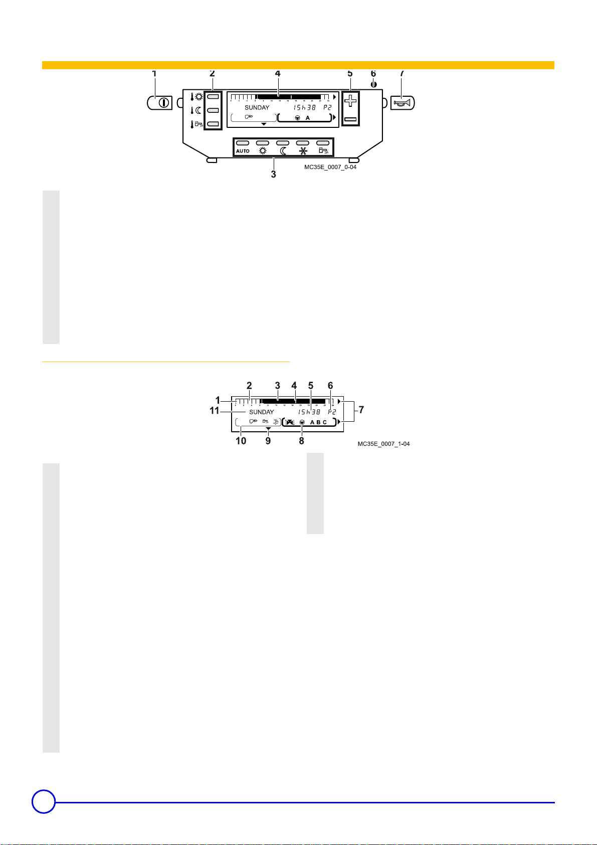
Control and display equipment
1
Main ON/OFF switch
2
Settings and programme keys
3
Operating mode selection keys
4
Programme display graphic bar (0 to 24 h)
5
Setting keys + and -
6
Alarm indicator / Start
The light is green when the boiler is operating
The red resetting button lights up when the burner is in the
safety condition
The flashing red light signals a sensor error
7
Reset button
Display
1
Graphic display bar for the program in circuit A, B or C (in
8)
area
2
Light area: indicates a "reduced" heating period or a "calorifier
heating not allowed" period
3
Dark area: indicates "comfort" heating period or a "calorifier
heating allowed" period
4
Flashing cursor showing the current time
5
Number display (current time, adjusted values, parameters,
etc.)
6
Active program display, P1, P2, P3, P4 or Su : automatic
“Summer“ cut-off
7
The arrows flash when setting values can be modified using
+ and - keys
the
8
Circuit operation symbols
: Status of the 3-way valve for the displayed circuit (If the
<
option is connected)
-> :
3-way valve opens
-
:
3-way valve closes
=
: Circulator pump on
:
A, B or C : circuit for which the parameters are displayed
9
mark displayed above the active mode key
10
Symbols indicating that the following inputs/outputs are active
: Burner on
D
: DHW load pump on
: Forced "summer" condition
#
11
Text display
4
INNOVENS - MC 35E / MC 45 / MC 65 / MC 90 21/03/05 - 300005222-001-A
Page 5

Keys accessible when the flap is closed Keys accessible when the flap is open
1 Temperature setting keys
: Daytime operating temperature (comfort)
2%
: Reduced operating temperature
2$
: Domestic hot water temperature
2
When one of these keys is pressed, the active time programme
corresponding to the circuit is displayed in the graphic bar.
2 Setting keys + and 3
Operating mode selection keys AUTO :
The following keys are used to override the
: forced operation at comfort temperature until midnignt
%
: forced operation at reduced temperature until midnight
$
: Antifreeze mode
%
: Tank filling enabled mode
automatic
AUTO mode
4 Key for access to setting and measurements
: Page scrolling
J
: Line scrolling
I
: Return to the previous line
H
5
: Manual "Summer" shutdown key
#
+ Su: The heating is shut down but the domestic hot water
#
function continues.
This function is independent of the "automatic heating
shutdown" function in summer when the outside
temperature exceeds the outside heating shutdown
temperature (in this case, only the symbol
display)
6
STANDARD : "Standard" program key.
STANDARD key for
C and is used to replace all customised programs with
and
their factory settings
P1 : Monday to Sunday : 6hours - 22hours
P2 : Monday to Sunday : 4hours - 21hours
P3 : Monday to Friday : 5hours - 8hours, 16hours - 22hours
Saturday and Sunday : 7hours - 23hours
P4 : Monday to Sunday : 6hours - 8hours, 11hours -
13hours30, 16hours - 22hours; Saturday : 6hours - 23hours;
Sunday : 7hours - 23hours
Hot water program : 5hours - 22hours (Reheating enabled)
Program AUXIL. : 6hours - 22hours
7
: Fitter settings access key
K
8 Programming keys
"Comfort" mode (in half-hours) program key or enable
%O
tank filling (dark area)
"Low" mode (in half-hours) program key or disable
$P
tank filling (light area)
Return to graph program bar
S
A.B.C Selection key for the displayed circuit A, B or C
PROG Displayed heating program selection key P1, P2, P3 or
P4. The regulator has 4 original heating programmes P1, P2,
P3 and P4 preset in the factory. See Table of programmes.
Programs P2, P3 and P4 may be customised. See
Customised programmes.
5 seconds activates P1 for circuits A, B
Su appears in the
Pressing the
21/03/05 - 300005222-001-A INNOVENS - MC 35E / MC 45 / MC 65 / MC 90
5
Page 6

Commissionning
The first start-up is to be performed by your installation
engineer
`Open the outlet and return valves
`Throw the main switch
`Open the gas valve
`Control switch 1 : Position
programme. The rest of the operation is automatic. The current
operating status is shown on the display.
`Check the pressure of the installation. Add water to the
installation if necessary.
The boiler is bled automatically.
After a prolonged shutdown, up to 5 start-up attempts may be made.
If the boiler does not start, the burner control module goes into error
mode and a message is displayed.
`Press the resetting button of the burner 2.
If the boiler does not start after several resets (5 attempts possible),
contact your heating engineer and inform him of the error message
displayed.
The boiler operates according to the settings programmed in the
factory.
. The boiler launches the start-up
8
Automatic mode
`Enter the desired temperature (5-30°C) using the + and - keys
and save using the AUTO key.
If the installation includes a B or C circuit: press the
keys
1x = input for circuit A
2x = input for circuit B
3x = input for circuit C
• Setting the domestic water temperature
`Press key
`Enter the desired temperature (10-80°C) using the + and - keys
and save using the AUTO key.
•Flap open
• Selection of the heating programme
`Lift the flap
2
2%
and
2$
• Flap closed
• Daytime temperature setting
`Press key
`Enter the desired temperature (5-30°C) using the + and - keys
and save using the AUTO key.
• Reduced temperature setting
`Press key
6
2%
2$
INNOVENS - MC 35E / MC 45 / MC 65 / MC 90 21/03/05 - 300005222-001-A
`Set the desired heating programme P1-P4 using the PROG key
Standard factory programming
Program
P1
P2*
P3*
P4*
*The heating programmes programmed in the factory can be set
individually.
`Close the flap
Daytime operation
Monday-Sunday 6-22 hours
Monday-Sunday 4-21 hours
Monday-Friday 5-8 hours; 16-
22 hours
Saturday-Sunday 7-23 hours
Monday-Friday 6-8 hours; 1113 hours 30, 16-22 hours
Saturday 6-23 hours
Sunday 7-23 hours
Page 7

• Activation of the automatic mode
`Press key AUTO : The operating mode is displayed above key
= Automatic operation of the heating programme set.
Forced operating modes
• Temporary comfort setting
Daytime setting for up to 24 hours
`Press key
Permanent comfort setting
`Press key
above key.
Return to the automatic setting
`Press key AUTO.
• Temporary reduced setting
Reduced operation for up to 24 hours
`Press key
Permanent reduced setting
. The operating mode is displayed above key.
%
for 5 sec.. The operating mode is displayed
%
. The operating mode is displayed above key
$
`Enter the number of days (1-99) using the + and - keys
`Press key AUTO. The operating mode is displayed above key.
Anti-freeze Off/On
`Press key
In the display area_: ANTI-FREEZE DAYS X
`Enter the number of days (0-0) using the + and - keys
`Press key AUTO
Immediate permanent anti-freeze setting
`Press key
above key.
Switch off permanent anti-freeze setting
`Press key AUTO
.
for 5 sec.. The operating mode is displayed
.
`Press key
key.
Return to the automatic setting
`Press key AUTO.
• Forced heating domestic hot water
Heating domestic hot water for up to 24 hours
`Press key
Permanent heating domestic hot water
`Press key
above key.
Return to the automatic domestic hot water programme
`Press key
• Manual summer mode
Activation manual summer setting
`Lift the flap
`Press key
and Su. The heating mode is deactivated while the heating
#
of domestic hot water continues to operate.
`Close the flap
for 1 sec.. The operating mode is displayed above
$
. The operating mode is displayed above key.
for 5 sec.. The operating mode is displayed
.
for 5 sec.. The operating mode is displayed by
#
Switch off manual summer setting
`Lift the flap
`Press key
`Close the flap
• Frost free
Immediate anti-freeze setting for 1 day
`Press key
In the display area_: ANTI-FREEZE DAYS 0
21/03/05 - 300005222-001-A INNOVENS - MC 35E / MC 45 / MC 65 / MC 90
for 5 sec..
#
. The operating mode is displayed above key.
.
7
Page 8

Checks to make before calling your fitter :
• The burner will not start
This may be caused by :
`Shutdown by the safety thermostat due to accidental
overheating. To restart the boiler : Press the resetting button of
the burner
`Shutdown of the safety system in connection with flue gas
evacuation. To restart the boiler : Press the resetting button of
the burner
contact your fitter. It is possible that the combustion products
evacuation pipe is totally or partially obstructed.
• The burner is operating but the radiators are cold
`Bleed the radiators
`Top up the primary circuit with water
`Check that the heating pump is operating correctly
Call your fitter nonetheless
• When you inform your fitter of an error, tell him :
`Product type,
. Call your fitter nonetheless.
. If interruptions of this kind happen repeatedly,
Troubleshooting
`Serial number : This information can be found on the rating
plate stuck to the inside of the control panel flap,
`Type of gas used (Natural gas or Propane)
8
INNOVENS - MC 35E / MC 45 / MC 65 / MC 90 21/03/05 - 300005222-001-A
Page 9

Warranty
You have just purchased a DE DIETRICH appliance and we thank you for the trust you have placed in our products.
Please note that your appliance will provide good service for a longer period of time if it is regularly checked and maintained.
Your fitter and the DE DIETRICH customer support network are at your disposal at all times.
Warranty terms
Starting from the purchase date shown on the original fitter's invoice, your appliance has a contractual guarantee against any
manufacturing defect.
The length of the guarantee is mentioned in the price catalogue.
The manufacturer is not liable for any improper use of the appliance or failure to maintain or install the unit correctly (the user shall take
care to ensure that the system is installed by a qualified fitter).
In particular, the manufacturer shall not be held responsible for any damage, loss or injury caused by installations which do not comply
with the following:
- applicable local laws and regulations
- specific requirements relating to the installation, such as national and/or local regulations
- the manufacturer's instructions, in particular those relating to the regular maintenance of the unit
- the rules of the profession
The warranty is limited to the exchange or repair of such parts as have been recognised to be faulty by our technical department and
does not cover labour, travel and carriage costs.
The warranty shall not apply to the replacement or repair of parts damaged by normal wear and tear, negligence, repairs by unqu alified
parties, faulty or insufficient monitoring and maintenance, faulty power supply or the use of unsuitable fuel.
Sub-assemblies such as motors, pumps, electric valves etc. are guaranteed only if they have never been dismantled.
France
The preceding dispositions are not exclusive of benefits for the purchaser of the legal guarantee as stated in Civil Code articles 1641
to 1648.
Belgium
The preceding dispositions about the contractual guarantee are not exclusive of profit if the need arises for the purchaser in Belgium
of the applicable legal dispositions on hidden defects.
Other countries
The above provisions do not restrict the benefit of the legal laws regarding hidden defects applicable in the buyer's country.
21/03/05 - 300005222-001-A INNOVENS - MC 35E / MC 45 / MC 65 / MC 90
9
Page 10

INNOVENS - MC 35E / MC 45 / MC 65 / MC 90 21/03/05 - 300005222-001-A
Page 11

INNOVENS - MC 35E / MC 45 / MC 65 / MC 90 21/03/05 - 300005222-001-A
Page 12

to change without notice
are continuously endeavouring to make improvements in product quality. All the specifications stated in this document are therefore subject
De Dietrich Thermique SAS
In the interest of customers,
 Loading...