

DeDietrich EVODENS PRO Series, AMC Pro 65, AMC Pro 90, AMC Pro 45, AMC Pro 115 Installation And User Manual
...Page 1
PROJECT
S U S T A I N A B L E C O M F O R T
®
EVODENS PRO
en
Istruzioni in ligua italiana disponibili su richiesta
High-efficiency wall-hung gas boiler
Installation and User Manual
AMC Pro 45 - 65 - 90 - 115
Diematic Evolution
Page 2

Dear Customer,
Thank you very much for buying this appliance.
Please read through the manual carefully before using the product, and keep it in a safe place for later reference. In order to
ensure continued safe and efficient operation we recommend that the product is serviced regularly. Our service and customer
service organisation can assist with this.
We hope you enjoy years of problem-free operation with the product.
Page 3

Contents
7725131 - v.01 - 06062019 AMC Pro 3
Contents
1 Safety . . . . . . . . . . . . . . . . . . . . . . . . . . . . . . . . . . . . . . . . . . . . . . . . . . . . . . . . . . . . . . . . . . . . . . . . . . . . . . . . . . . . . . . . . . . . 6
1.1 General safety instructions . . . . . . . . . . . . . . . . . . . . . . . . . . . . . . . . . . . . . . . . . . . . . . . . . . . . . . . . . . . . . . . . . . . . . . . 6
1.1.1 For the installer . . . . . . . . . . . . . . . . . . . . . . . . . . . . . . . . . . . . . . . . . . . . . . . . . . . . . . . . . . . . . . . . . . . . . . . . 6
1.1.2 For the end user . . . . . . . . . . . . . . . . . . . . . . . . . . . . . . . . . . . . . . . . . . . . . . . . . . . . . . . . . . . . . . . . . . . . . . . 7
1.2 Recommendations . . . . . . . . . . . . . . . . . . . . . . . . . . . . . . . . . . . . . . . . . . . . . . . . . . . . . . . . . . . . . . . . . . . . . . . . . . . . . 8
1.3 Liabilities . . . . . . . . . . . . . . . . . . . . . . . . . . . . . . . . . . . . . . . . . . . . . . . . . . . . . . . . . . . . . . . . . . . . . . . . . . . . . . . . . . . . 10
1.3.1 Manufacturer's liability . . . . . . . . . . . . . . . . . . . . . . . . . . . . . . . . . . . . . . . . . . . . . . . . . . . . . . . . . . . . . . . . . . 10
1.3.2 Installer's liability . . . . . . . . . . . . . . . . . . . . . . . . . . . . . . . . . . . . . . . . . . . . . . . . . . . . . . . . . . . . . . . . . . . . . . 10
1.3.3 User's liability . . . . . . . . . . . . . . . . . . . . . . . . . . . . . . . . . . . . . . . . . . . . . . . . . . . . . . . . . . . . . . . . . . . . . . . . .10
2 About this manual . . . . . . . . . . . . . . . . . . . . . . . . . . . . . . . . . . . . . . . . . . . . . . . . . . . . . . . . . . . . . . . . . . . . . . . . . . . . . . . . . . 11
2.1 Additional documentation . . . . . . . . . . . . . . . . . . . . . . . . . . . . . . . . . . . . . . . . . . . . . . . . . . . . . . . . . . . . . . . . . . . . . . . 11
2.2 Symbols used in the manual . . . . . . . . . . . . . . . . . . . . . . . . . . . . . . . . . . . . . . . . . . . . . . . . . . . . . . . . . . . . . . . . . . . . .11
3 Description of the product . . . . . . . . . . . . . . . . . . . . . . . . . . . . . . . . . . . . . . . . . . . . . . . . . . . . . . . . . . . . . . . . . . . . . . . . . . . . 12
3.1 General description . . . . . . . . . . . . . . . . . . . . . . . . . . . . . . . . . . . . . . . . . . . . . . . . . . . . . . . . . . . . . . . . . . . . . . . . . . . .12
3.2 Main components . . . . . . . . . . . . . . . . . . . . . . . . . . . . . . . . . . . . . . . . . . . . . . . . . . . . . . . . . . . . . . . . . . . . . . . . . . . . . 12
3.3 Dimensions and connections . . . . . . . . . . . . . . . . . . . . . . . . . . . . . . . . . . . . . . . . . . . . . . . . . . . . . . . . . . . . . . . . . . . . 13
3.4 Introduction to the controls platform . . . . . . . . . . . . . . . . . . . . . . . . . . . . . . . . . . . . . . . . . . . . . . . . . . . . . . . . . . . . . . . 13
4 Preparation of installation . . . . . . . . . . . . . . . . . . . . . . . . . . . . . . . . . . . . . . . . . . . . . . . . . . . . . . . . . . . . . . . . . . . . . . . . . . . . 15
4.1 Installation regulations . . . . . . . . . . . . . . . . . . . . . . . . . . . . . . . . . . . . . . . . . . . . . . . . . . . . . . . . . . . . . . . . . . . . . . . . . 15
4.2 Choice of the location . . . . . . . . . . . . . . . . . . . . . . . . . . . . . . . . . . . . . . . . . . . . . . . . . . . . . . . . . . . . . . . . . . . . . . . . . . 15
4.3 Requirements for CH water connections . . . . . . . . . . . . . . . . . . . . . . . . . . . . . . . . . . . . . . . . . . . . . . . . . . . . . . . . . . . 16
4.4 Requirements for condensate drain line . . . . . . . . . . . . . . . . . . . . . . . . . . . . . . . . . . . . . . . . . . . . . . . . . . . . . . . . . . . . 16
4.5 Requirements for gas connection . . . . . . . . . . . . . . . . . . . . . . . . . . . . . . . . . . . . . . . . . . . . . . . . . . . . . . . . . . . . . . . . . 16
4.6 Requirements for the electrical connections . . . . . . . . . . . . . . . . . . . . . . . . . . . . . . . . . . . . . . . . . . . . . . . . . . . . . . . . . 16
4.7 Requirements for the flue gas outlet system . . . . . . . . . . . . . . . . . . . . . . . . . . . . . . . . . . . . . . . . . . . . . . . . . . . . . . . . .17
4.7.1 Classification . . . . . . . . . . . . . . . . . . . . . . . . . . . . . . . . . . . . . . . . . . . . . . . . . . . . . . . . . . . . . . . . . . . . . . . . . 17
4.7.2 Material . . . . . . . . . . . . . . . . . . . . . . . . . . . . . . . . . . . . . . . . . . . . . . . . . . . . . . . . . . . . . . . . . . . . . . . . . . . . . 19
4.7.3 Dimensions of flue gas outlet pipe . . . . . . . . . . . . . . . . . . . . . . . . . . . . . . . . . . . . . . . . . . . . . . . . . . . . . . . . .20
4.7.4 Length of the air and flue gas pipes . . . . . . . . . . . . . . . . . . . . . . . . . . . . . . . . . . . . . . . . . . . . . . . . . . . . . . . .21
4.7.5 Additional guidelines . . . . . . . . . . . . . . . . . . . . . . . . . . . . . . . . . . . . . . . . . . . . . . . . . . . . . . . . . . . . . . . . . . . 23
4.8 Water quality and water treatment . . . . . . . . . . . . . . . . . . . . . . . . . . . . . . . . . . . . . . . . . . . . . . . . . . . . . . . . . . . . . . . . 24
4.9 Process heat application . . . . . . . . . . . . . . . . . . . . . . . . . . . . . . . . . . . . . . . . . . . . . . . . . . . . . . . . . . . . . . . . . . . . . . . .24
4.10 Increase default ΔT setting . . . . . . . . . . . . . . . . . . . . . . . . . . . . . . . . . . . . . . . . . . . . . . . . . . . . . . . . . . . . . . . . . . . . . . 24
4.11 Installation examples . . . . . . . . . . . . . . . . . . . . . . . . . . . . . . . . . . . . . . . . . . . . . . . . . . . . . . . . . . . . . . . . . . . . . . . . . . .25
4.11.1 Symbols used . . . . . . . . . . . . . . . . . . . . . . . . . . . . . . . . . . . . . . . . . . . . . . . . . . . . . . . . . . . . . . . . . . . . . . . . 25
4.11.2 Connection example 4 . . . . . . . . . . . . . . . . . . . . . . . . . . . . . . . . . . . . . . . . . . . . . . . . . . . . . . . . . . . . . . . . . . 27
4.11.3 Connection example 6 . . . . . . . . . . . . . . . . . . . . . . . . . . . . . . . . . . . . . . . . . . . . . . . . . . . . . . . . . . . . . . . . . . 29
4.11.4 Connection example 16 . . . . . . . . . . . . . . . . . . . . . . . . . . . . . . . . . . . . . . . . . . . . . . . . . . . . . . . . . . . . . . . . . 32
5 Installation . . . . . . . . . . . . . . . . . . . . . . . . . . . . . . . . . . . . . . . . . . . . . . . . . . . . . . . . . . . . . . . . . . . . . . . . . . . . . . . . . . . . . . . . 35
5.1 Positioning the boiler . . . . . . . . . . . . . . . . . . . . . . . . . . . . . . . . . . . . . . . . . . . . . . . . . . . . . . . . . . . . . . . . . . . . . . . . . . .35
5.2 Mounting an outdoor sensor . . . . . . . . . . . . . . . . . . . . . . . . . . . . . . . . . . . . . . . . . . . . . . . . . . . . . . . . . . . . . . . . . . . . . 35
5.2.1 Positions to be avoided . . . . . . . . . . . . . . . . . . . . . . . . . . . . . . . . . . . . . . . . . . . . . . . . . . . . . . . . . . . . . . . . . 35
5.2.2 Recommended positions . . . . . . . . . . . . . . . . . . . . . . . . . . . . . . . . . . . . . . . . . . . . . . . . . . . . . . . . . . . . . . . . 35
5.2.3 Fitting the outdoor sensor . . . . . . . . . . . . . . . . . . . . . . . . . . . . . . . . . . . . . . . . . . . . . . . . . . . . . . . . . . . . . . . 36
5.3 Rinsing the system . . . . . . . . . . . . . . . . . . . . . . . . . . . . . . . . . . . . . . . . . . . . . . . . . . . . . . . . . . . . . . . . . . . . . . . . . . . . 36
5.4 Connecting the heating circuit . . . . . . . . . . . . . . . . . . . . . . . . . . . . . . . . . . . . . . . . . . . . . . . . . . . . . . . . . . . . . . . . . . . .37
5.5 Connecting the condensate discharge pipe . . . . . . . . . . . . . . . . . . . . . . . . . . . . . . . . . . . . . . . . . . . . . . . . . . . . . . . . . 37
5.6 Gas connection . . . . . . . . . . . . . . . . . . . . . . . . . . . . . . . . . . . . . . . . . . . . . . . . . . . . . . . . . . . . . . . . . . . . . . . . . . . . . . . 38
5.7 Air supply/flue gas outlet connections . . . . . . . . . . . . . . . . . . . . . . . . . . . . . . . . . . . . . . . . . . . . . . . . . . . . . . . . . . . . . .38
5.7.1 Connecting the flue gas outlet and air supply . . . . . . . . . . . . . . . . . . . . . . . . . . . . . . . . . . . . . . . . . . . . . . . . 38
5.8 Electrical connections . . . . . . . . . . . . . . . . . . . . . . . . . . . . . . . . . . . . . . . . . . . . . . . . . . . . . . . . . . . . . . . . . . . . . . . . . . 38
5.8.1 Control unit . . . . . . . . . . . . . . . . . . . . . . . . . . . . . . . . . . . . . . . . . . . . . . . . . . . . . . . . . . . . . . . . . . . . . . . . . . 38
5.8.2 Access to the instrument box . . . . . . . . . . . . . . . . . . . . . . . . . . . . . . . . . . . . . . . . . . . . . . . . . . . . . . . . . . . . .39
5.8.3 Connection options for the standard PCB - CB-03 . . . . . . . . . . . . . . . . . . . . . . . . . . . . . . . . . . . . . . . . . . . . 39
5.8.4 Access to the expansion box . . . . . . . . . . . . . . . . . . . . . . . . . . . . . . . . . . . . . . . . . . . . . . . . . . . . . . . . . . . . .42
5.8.5 Connection options for the expansion PCB - SCB-10 . . . . . . . . . . . . . . . . . . . . . . . . . . . . . . . . . . . . . . . . . . 43
5.8.6 Connecting the standard pump . . . . . . . . . . . . . . . . . . . . . . . . . . . . . . . . . . . . . . . . . . . . . . . . . . . . . . . . . . . 46
5.8.7 Connecting the PWM pump . . . . . . . . . . . . . . . . . . . . . . . . . . . . . . . . . . . . . . . . . . . . . . . . . . . . . . . . . . . . . .47
6 Preparation of commissioning . . . . . . . . . . . . . . . . . . . . . . . . . . . . . . . . . . . . . . . . . . . . . . . . . . . . . . . . . . . . . . . . . . . . . . . . .48
Page 4

Contents
4 AMC Pro 7725131 - v.01 - 06062019
6.1 Checklist before commissioning . . . . . . . . . . . . . . . . . . . . . . . . . . . . . . . . . . . . . . . . . . . . . . . . . . . . . . . . . . . . . . . . . . 48
6.1.1 Filling the siphon . . . . . . . . . . . . . . . . . . . . . . . . . . . . . . . . . . . . . . . . . . . . . . . . . . . . . . . . . . . . . . . . . . . . . . 48
6.1.2 Filling the system . . . . . . . . . . . . . . . . . . . . . . . . . . . . . . . . . . . . . . . . . . . . . . . . . . . . . . . . . . . . . . . . . . . . . .48
6.1.3 Gas circuit . . . . . . . . . . . . . . . . . . . . . . . . . . . . . . . . . . . . . . . . . . . . . . . . . . . . . . . . . . . . . . . . . . . . . . . . . . . 48
6.1.4 Hydraulic circuit . . . . . . . . . . . . . . . . . . . . . . . . . . . . . . . . . . . . . . . . . . . . . . . . . . . . . . . . . . . . . . . . . . . . . . . 49
6.1.5 Electrical connections . . . . . . . . . . . . . . . . . . . . . . . . . . . . . . . . . . . . . . . . . . . . . . . . . . . . . . . . . . . . . . . . . . 49
6.2 Control panel description . . . . . . . . . . . . . . . . . . . . . . . . . . . . . . . . . . . . . . . . . . . . . . . . . . . . . . . . . . . . . . . . . . . . . . . 49
6.2.1 Control panel components . . . . . . . . . . . . . . . . . . . . . . . . . . . . . . . . . . . . . . . . . . . . . . . . . . . . . . . . . . . . . . .49
6.2.2 Description of the home screen . . . . . . . . . . . . . . . . . . . . . . . . . . . . . . . . . . . . . . . . . . . . . . . . . . . . . . . . . . .49
6.2.3 Description of the main menu . . . . . . . . . . . . . . . . . . . . . . . . . . . . . . . . . . . . . . . . . . . . . . . . . . . . . . . . . . . . 50
7 Commissioning . . . . . . . . . . . . . . . . . . . . . . . . . . . . . . . . . . . . . . . . . . . . . . . . . . . . . . . . . . . . . . . . . . . . . . . . . . . . . . . . . . . . 51
7.1 Commissioning procedure . . . . . . . . . . . . . . . . . . . . . . . . . . . . . . . . . . . . . . . . . . . . . . . . . . . . . . . . . . . . . . . . . . . . . . 51
7.2 Gas settings . . . . . . . . . . . . . . . . . . . . . . . . . . . . . . . . . . . . . . . . . . . . . . . . . . . . . . . . . . . . . . . . . . . . . . . . . . . . . . . . . 51
7.2.1 Factory setting . . . . . . . . . . . . . . . . . . . . . . . . . . . . . . . . . . . . . . . . . . . . . . . . . . . . . . . . . . . . . . . . . . . . . . . . 51
7.2.2 Adjusting to a different gas type . . . . . . . . . . . . . . . . . . . . . . . . . . . . . . . . . . . . . . . . . . . . . . . . . . . . . . . . . . 51
7.2.3 Checking and setting the gas/air ratio . . . . . . . . . . . . . . . . . . . . . . . . . . . . . . . . . . . . . . . . . . . . . . . . . . . . . . 53
7.3 Final instructions . . . . . . . . . . . . . . . . . . . . . . . . . . . . . . . . . . . . . . . . . . . . . . . . . . . . . . . . . . . . . . . . . . . . . . . . . . . . . . 56
8 Settings . . . . . . . . . . . . . . . . . . . . . . . . . . . . . . . . . . . . . . . . . . . . . . . . . . . . . . . . . . . . . . . . . . . . . . . . . . . . . . . . . . . . . . . . . . 57
8.1 Introduction to parameter codes . . . . . . . . . . . . . . . . . . . . . . . . . . . . . . . . . . . . . . . . . . . . . . . . . . . . . . . . . . . . . . . . . . 57
8.2 Changing the parameters . . . . . . . . . . . . . . . . . . . . . . . . . . . . . . . . . . . . . . . . . . . . . . . . . . . . . . . . . . . . . . . . . . . . . . . 57
8.2.1 Accessing the installer level . . . . . . . . . . . . . . . . . . . . . . . . . . . . . . . . . . . . . . . . . . . . . . . . . . . . . . . . . . . . . .57
8.2.2 Changing boiler parameters when SCB-10 is fitted . . . . . . . . . . . . . . . . . . . . . . . . . . . . . . . . . . . . . . . . . . . .58
8.2.3 Setting the maximum load for CH operation . . . . . . . . . . . . . . . . . . . . . . . . . . . . . . . . . . . . . . . . . . . . . . . . . 59
8.2.4 Setting the heating curve . . . . . . . . . . . . . . . . . . . . . . . . . . . . . . . . . . . . . . . . . . . . . . . . . . . . . . . . . . . . . . . .60
8.2.5 Setting for process heat application . . . . . . . . . . . . . . . . . . . . . . . . . . . . . . . . . . . . . . . . . . . . . . . . . . . . . . . .60
8.2.6 Changing the default ΔT setting . . . . . . . . . . . . . . . . . . . . . . . . . . . . . . . . . . . . . . . . . . . . . . . . . . . . . . . . . . 61
8.3 List of parameters . . . . . . . . . . . . . . . . . . . . . . . . . . . . . . . . . . . . . . . . . . . . . . . . . . . . . . . . . . . . . . . . . . . . . . . . . . . . . 61
8.3.1 Control unit settings . . . . . . . . . . . . . . . . . . . . . . . . . . . . . . . . . . . . . . . . . . . . . . . . . . . . . . . . . . . . . . . . . . . .61
8.3.2 SCB-10 expansion PCB settings . . . . . . . . . . . . . . . . . . . . . . . . . . . . . . . . . . . . . . . . . . . . . . . . . . . . . . . . . .67
9 User instructions . . . . . . . . . . . . . . . . . . . . . . . . . . . . . . . . . . . . . . . . . . . . . . . . . . . . . . . . . . . . . . . . . . . . . . . . . . . . . . . . . . . 68
9.1 Accessing the user level menus . . . . . . . . . . . . . . . . . . . . . . . . . . . . . . . . . . . . . . . . . . . . . . . . . . . . . . . . . . . . . . . . . . 68
9.2 Home screen . . . . . . . . . . . . . . . . . . . . . . . . . . . . . . . . . . . . . . . . . . . . . . . . . . . . . . . . . . . . . . . . . . . . . . . . . . . . . . . . .68
9.3 Activating holiday programs for all zones . . . . . . . . . . . . . . . . . . . . . . . . . . . . . . . . . . . . . . . . . . . . . . . . . . . . . . . . . . . 69
9.4 Heating circuit configuration . . . . . . . . . . . . . . . . . . . . . . . . . . . . . . . . . . . . . . . . . . . . . . . . . . . . . . . . . . . . . . . . . . . . . 69
9.5 Changing the room temperature of a zone . . . . . . . . . . . . . . . . . . . . . . . . . . . . . . . . . . . . . . . . . . . . . . . . . . . . . . . . . . 70
9.5.1 Definition of zone . . . . . . . . . . . . . . . . . . . . . . . . . . . . . . . . . . . . . . . . . . . . . . . . . . . . . . . . . . . . . . . . . . . . . .70
9.5.2 Changing the name and symbol of a zone . . . . . . . . . . . . . . . . . . . . . . . . . . . . . . . . . . . . . . . . . . . . . . . . . . 70
9.5.3 Changing the operating mode of a zone . . . . . . . . . . . . . . . . . . . . . . . . . . . . . . . . . . . . . . . . . . . . . . . . . . . . 70
9.5.4 Timer program to control the room temperature . . . . . . . . . . . . . . . . . . . . . . . . . . . . . . . . . . . . . . . . . . . . . . 71
9.5.5 Changing the heating activity temperatures . . . . . . . . . . . . . . . . . . . . . . . . . . . . . . . . . . . . . . . . . . . . . . . . . 72
9.5.6 Changing the room temperature temporarily . . . . . . . . . . . . . . . . . . . . . . . . . . . . . . . . . . . . . . . . . . . . . . . . . 72
9.6 Changing the domestic hot water temperature . . . . . . . . . . . . . . . . . . . . . . . . . . . . . . . . . . . . . . . . . . . . . . . . . . . . . . . 73
9.6.1 Changing the domestic hot water operating mode . . . . . . . . . . . . . . . . . . . . . . . . . . . . . . . . . . . . . . . . . . . . 73
9.6.2 Timer program to control the DHW temperature . . . . . . . . . . . . . . . . . . . . . . . . . . . . . . . . . . . . . . . . . . . . . . 73
9.6.3 Increasing the domestic hot water temperature temporarily . . . . . . . . . . . . . . . . . . . . . . . . . . . . . . . . . . . . . 74
9.6.4 Changing the comfort hot water temperature . . . . . . . . . . . . . . . . . . . . . . . . . . . . . . . . . . . . . . . . . . . . . . . . 74
9.7 Switching the central heating on or off . . . . . . . . . . . . . . . . . . . . . . . . . . . . . . . . . . . . . . . . . . . . . . . . . . . . . . . . . . . . . 74
9.8 Changing the display settings . . . . . . . . . . . . . . . . . . . . . . . . . . . . . . . . . . . . . . . . . . . . . . . . . . . . . . . . . . . . . . . . . . . . 74
9.9 Reading the installer's name and phone number . . . . . . . . . . . . . . . . . . . . . . . . . . . . . . . . . . . . . . . . . . . . . . . . . . . . . 75
9.10 Start-up . . . . . . . . . . . . . . . . . . . . . . . . . . . . . . . . . . . . . . . . . . . . . . . . . . . . . . . . . . . . . . . . . . . . . . . . . . . . . . . . . . . . . 75
9.11 Shutdown . . . . . . . . . . . . . . . . . . . . . . . . . . . . . . . . . . . . . . . . . . . . . . . . . . . . . . . . . . . . . . . . . . . . . . . . . . . . . . . . . . . 75
9.12 Frost protection . . . . . . . . . . . . . . . . . . . . . . . . . . . . . . . . . . . . . . . . . . . . . . . . . . . . . . . . . . . . . . . . . . . . . . . . . . . . . . . 75
9.13 Cleaning the casing . . . . . . . . . . . . . . . . . . . . . . . . . . . . . . . . . . . . . . . . . . . . . . . . . . . . . . . . . . . . . . . . . . . . . . . . . . . 75
10 Technical specifications . . . . . . . . . . . . . . . . . . . . . . . . . . . . . . . . . . . . . . . . . . . . . . . . . . . . . . . . . . . . . . . . . . . . . . . . . . . . . 76
10.1 Homologations . . . . . . . . . . . . . . . . . . . . . . . . . . . . . . . . . . . . . . . . . . . . . . . . . . . . . . . . . . . . . . . . . . . . . . . . . . . . . . . 76
10.1.1 Certifications . . . . . . . . . . . . . . . . . . . . . . . . . . . . . . . . . . . . . . . . . . . . . . . . . . . . . . . . . . . . . . . . . . . . . . . . . 76
10.1.2 Unit categories . . . . . . . . . . . . . . . . . . . . . . . . . . . . . . . . . . . . . . . . . . . . . . . . . . . . . . . . . . . . . . . . . . . . . . . .76
10.1.3 Directives . . . . . . . . . . . . . . . . . . . . . . . . . . . . . . . . . . . . . . . . . . . . . . . . . . . . . . . . . . . . . . . . . . . . . . . . . . . . 77
10.1.4 Factory test . . . . . . . . . . . . . . . . . . . . . . . . . . . . . . . . . . . . . . . . . . . . . . . . . . . . . . . . . . . . . . . . . . . . . . . . . . 77
10.2 Technical data . . . . . . . . . . . . . . . . . . . . . . . . . . . . . . . . . . . . . . . . . . . . . . . . . . . . . . . . . . . . . . . . . . . . . . . . . . . . . . . .77
10.3 Circulating pump . . . . . . . . . . . . . . . . . . . . . . . . . . . . . . . . . . . . . . . . . . . . . . . . . . . . . . . . . . . . . . . . . . . . . . . . . . . . . . 80
Page 5

Contents
7725131 - v.01 - 06062019 AMC Pro 5
11 Appendix . . . . . . . . . . . . . . . . . . . . . . . . . . . . . . . . . . . . . . . . . . . . . . . . . . . . . . . . . . . . . . . . . . . . . . . . . . . . . . . . . . . . . . . . . 82
11.1 ErP information . . . . . . . . . . . . . . . . . . . . . . . . . . . . . . . . . . . . . . . . . . . . . . . . . . . . . . . . . . . . . . . . . . . . . . . . . . . . . . . 82
11.1.1 Product fiche . . . . . . . . . . . . . . . . . . . . . . . . . . . . . . . . . . . . . . . . . . . . . . . . . . . . . . . . . . . . . . . . . . . . . . . . . 82
11.1.2 Package sheet . . . . . . . . . . . . . . . . . . . . . . . . . . . . . . . . . . . . . . . . . . . . . . . . . . . . . . . . . . . . . . . . . . . . . . . . 83
11.2 EC declaration of conformity . . . . . . . . . . . . . . . . . . . . . . . . . . . . . . . . . . . . . . . . . . . . . . . . . . . . . . . . . . . . . . . . . . . . .84
Page 6
1 Safety
6 AMC Pro 7725131 - v.01 - 06062019
1 Safety
1.1 General safety instructions
1.1.1 For the installer
Danger
If you smell gas:
1. Do not use naked flames, do not smoke and
do not operate electrical contacts or switches
(doorbell, lighting, motor, lift etc.).
2. Shut off the gas supply.
3. Open the windows.
4. Trace possible leaks and seal them off
immediately.
5. If the leak is upstream of the gas meter, notify
the gas company.
Danger
If you smell flue gases:
1. Switch the boiler off.
2. Open the windows.
3. Trace possible leaks and seal them off
immediately.
Caution
After maintenance or repair work, check the
entire heating installation to ensure that there are
no leaks.
Page 7
1 Safety
7725131 - v.01 - 06062019 AMC Pro 7
1.1.2
For the end user
Danger
If you smell gas:
1. Do not use naked flames, do not smoke and
do not operate electrical contacts or switches
(doorbell, lighting, motor, lift etc.).
2. Shut off the gas supply.
3. Open the windows.
4. Evacuate the property.
5. Contact a qualified installer.
Danger
If you smell flue gases:
1. Switch the boiler off.
2. Open the windows.
3. Evacuate the property.
4. Contact a qualified installer.
Warning
Do not touch the flue gas pipes. Depending on
the boiler settings, the temperature of the flue gas
pipes can rise to over 60°C.
Warning
Do not touch radiators for long periods.
Depending on the boiler settings, the temperature
of the radiators can rise to over 60°C.
Warning
Be careful when using the domestic hot water.
Depending on the boiler settings, the temperature
of domestic hot water can rise to over 65°C.
Warning
The use of the boiler and the installation by you
as the end-user must be limited to the operations
described in this manual. All other actions may
only be undertaken by a qualified fitter/engineer.
Warning
The condensate drain must not be modified or
sealed. If a condensate neutralisation system is
used, the system must be cleaned regularly in
accordance with the instructions provided by the
manufacturer.
Page 8
1 Safety
8 AMC Pro 7725131 - v.01 - 06062019
1.2 Recommendations
Caution
Ensure that the boiler is regularly serviced.
Contact a qualified installer or arrange a
maintenance contract for the servicing of the
boiler.
Caution
Only genuine spare parts may be used.
Important
Regularly check for the presence of water and
pressure in the heating installation.
Danger
This appliance can be used by children aged
eight and above and people with a physical,
sensory or mental disability, or with a lack of
experience and knowledge, provided they are
supervised and instructed in how to use the
appliance in a safe manner and understand the
associated dangers. Children must not be
allowed to play with the appliance. Cleaning and
user maintenance should not be carried out by
children without adult supervision.
Warning
Installation and maintenance of the boiler must be
carried out by a qualified installer in accordance
with local and national regulations.
Warning
The installation and maintenance of the boiler
must be undertaken by a qualified installer in
accordance with the information in the supplied
manual, doing otherwise may result in dangerous
situations and/or bodily injury.
Warning
Removal and disposal of the boiler must be
carried out by a qualified installer in accordance
with local and national regulations.
Warning
If the mains lead is damaged, it must be replaced
by the original manufacturer, the manufacturer's
dealer or another suitably skilled person to
prevent hazardous situations from arising.
Page 9
1 Safety
7725131 - v.01 - 06062019 AMC Pro 9
Warning
Always disconnect the mains supply and close
the main gas tap when working on the boiler.
Warning
Check the entire system for leaks after
maintenance and servicing work.
Danger
For safety reasons, we recommend fitting smoke
and CO alarms at suitable places in your home.
Caution
Make sure the boiler can be reached at all
times.
The boiler must be installed in a frost-free area.
If the power cord is permanently connected, you
must always install a main bipolar switch with
an opening gap of at least 3 mm (EN 60335-1).
Drain the boiler and central heating system if
you are not going to use your home for a long
time and there is a chance of frost.
The frost protection does not work if the boiler is
out of operation.
The boiler protection only protects the boiler,
not the system.
Check the water pressure in the system
regularly. If the water pressure is lower than 0.8
bar, the system must be topped up
(recommended water pressure between 1.5 and
2 bar).
Important
Keep this document near to the boiler.
Important
Only remove the casing for maintenance and
repair operations. Refit all panels when
maintenance work and servicing are complete.
Important
Instruction and warning labels must never be
removed or covered and must be clearly legible
throughout the entire service life of the boiler.
Damaged or illegible instructions and warning
stickers must be replaced immediately.
Important
Modifications to the boiler require the written
approval of De Dietrich.
Page 10

1 Safety
10 AMC Pro 7725131 - v.01 - 06062019
1.3 Liabilities
1.3.1 Manufacturer's liability
Our products are manufactured in compliance with the
requirements of the various Directives applicable. They
are therefore delivered with the marking and any
documents necessary. In the interests of the quality of
our products, we strive constantly to improve them. We
therefore reserve the right to modify the specifications
given in this document.
Our liability as manufacturer may not be invoked in the
following cases:
Failure to abide by the instructions on installing and
maintaining the appliance.
Failure to abide by the instructions on using the
appliance.
Faulty or insufficient maintenance of the appliance.
1.3.2
Installer's liability
The installer is responsible for the installation and initial
commissioning of the appliance. The installer must
observe the following instructions:
Read and follow the instructions given in the manuals
provided with the appliance.
Install the appliance in compliance with prevailing
legislation and standards.
Carry out initial commissioning and any checks
necessary.
Explain the installation to the user.
If maintenance is necessary, warn the user of the
obligation to check the appliance and keep it in good
working order.
Give all the instruction manuals to the user.
1.3.3 User's liability
To guarantee optimum operation of the system, you
must abide by the following instructions:
Read and follow the instructions given in the manuals
provided with the appliance.
Call on a qualified professional to carry out installation
and initial commissioning.
Get your installer to explain your installation to you.
Have the required inspections and maintenance
carried out by a qualified installer.
Keep the instruction manuals in good condition close
to the appliance.
Page 11
2 About this manual
7725131 - v.01 - 06062019 AMC Pro 11
2.1 Additional documentation
2 About this manual
The following documentation is available in addition to this manual:
Service manual
Water quality instructions
2.2
Symbols used in the manual
This manual contains special instructions, marked with specific symbols.
Please pay extra attention when these symbols are used.
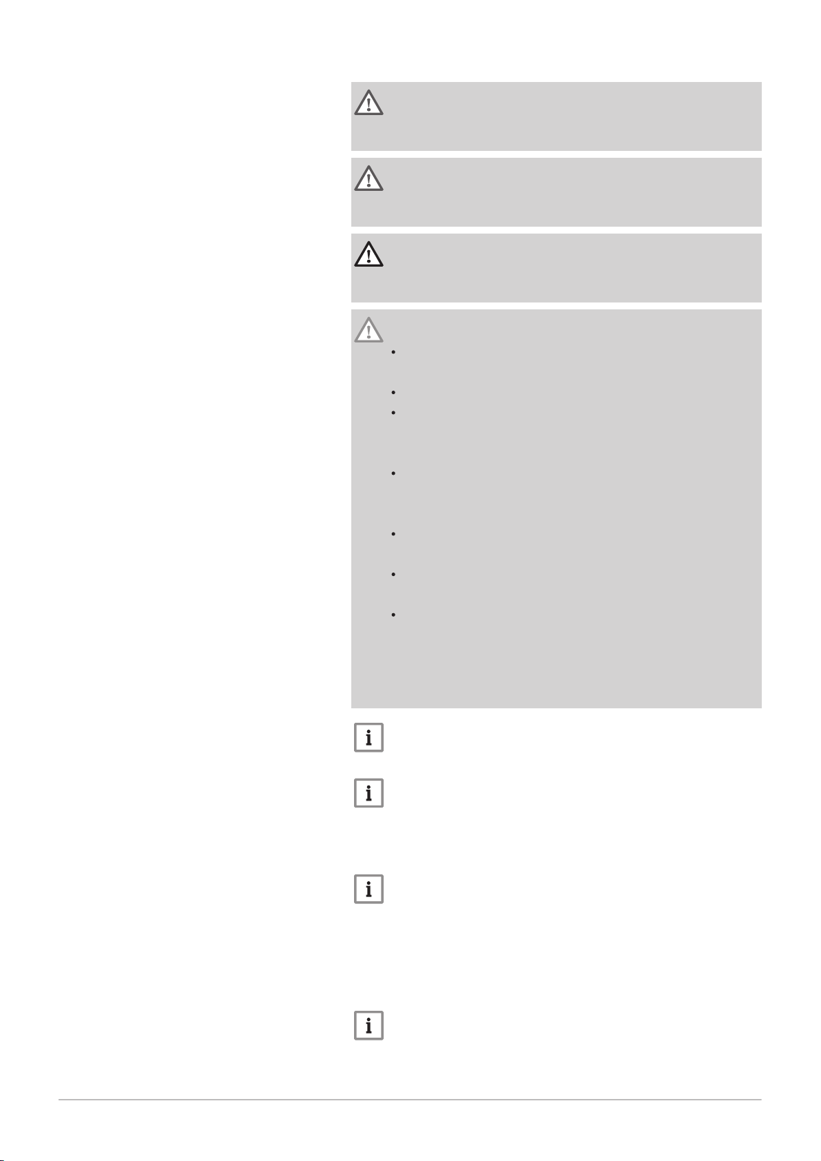
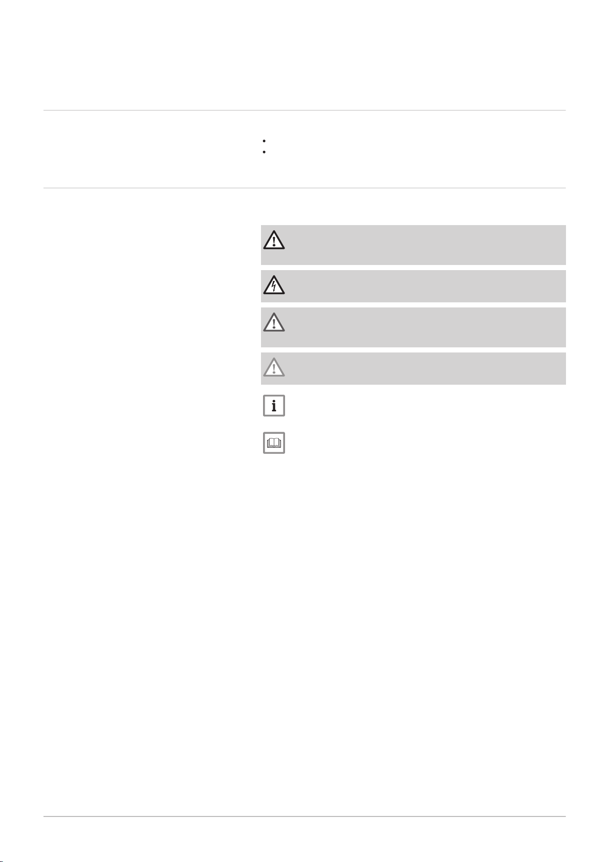
Danger
Risk of dangerous situations that may result in serious personal
injury.
Danger of electric shock
Risk of electric shock that may result in serious personal injury.
Warning
Risk of dangerous situations that may result in minor personal
injury.
Caution
Risk of material damage.
Important
Please note: important information.
See
Reference to other manuals or pages in this manual.
Page 12
AD-4000070-01
17
14
13
10
9
6
7
8
2
1
12
3
4
11
5
18
19
20
16
15
3 Description of the product
12 AMC Pro 7725131 - v.01 - 06062019
3 Description of the product
3.1 General description
The AMC Pro boiler is a high-efficiency wall-hung gas boiler with the
following properties:
High-efficiency heating.
Limited emissions of polluting substances.
Ideal choice for cascade configurations.
All AMC Pro boiler models are supplied without a pump, but with the
required pump connection cables.
Take the boiler resistance and system resistance into account when
selecting a pump.
Caution
The pump may have a maximum input of 200 W. Use an auxiliary
relay for a pump with greater power.
If possible, install the pump directly under the boiler on the return
connection.
3.2 Main components
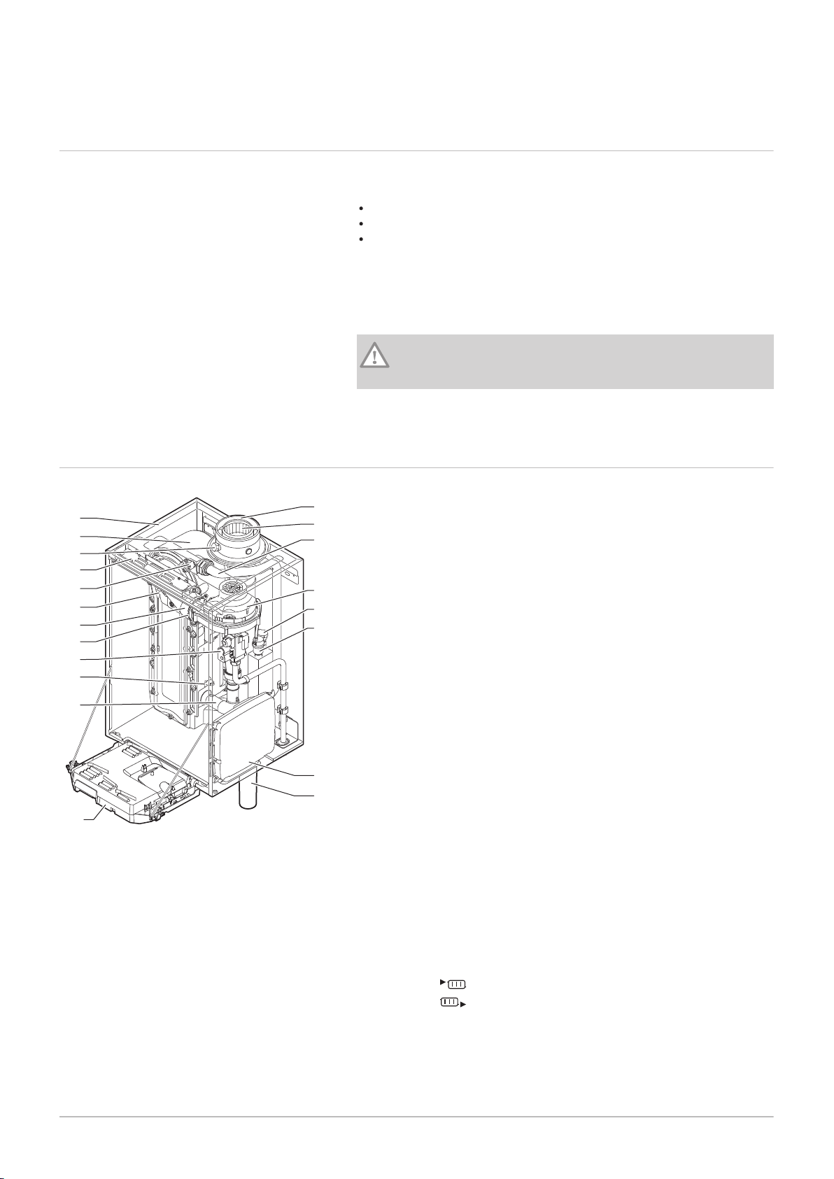
Fig.1
Main components
1
Casing/air box
2
Heat exchanger (CH)
3
Interior light
4
Type plate
5
Flow sensor
6
Ionisation/ignition electrode
7
Mixing tube
8
Non-return valve
9
Combined gas valve unit
10
Return sensor
11
Air intake silencer
12
Instrument box
13
Siphon
14
Expansion box for the control PCBs
15
Automatic air vent
16
Hydraulic pressure sensor
17
Fan
18
Supply line
19
Flue gas measuring point
20
Flue gas discharge pipe
21
Air supply
Heating circuit flow
Heating circuit return
Page 13
3.3 Dimensions and connections
AD-4100113-02
500
100
50
191
500
750
50
130
191
365
7725131 - v.01 - 06062019 AMC Pro 13
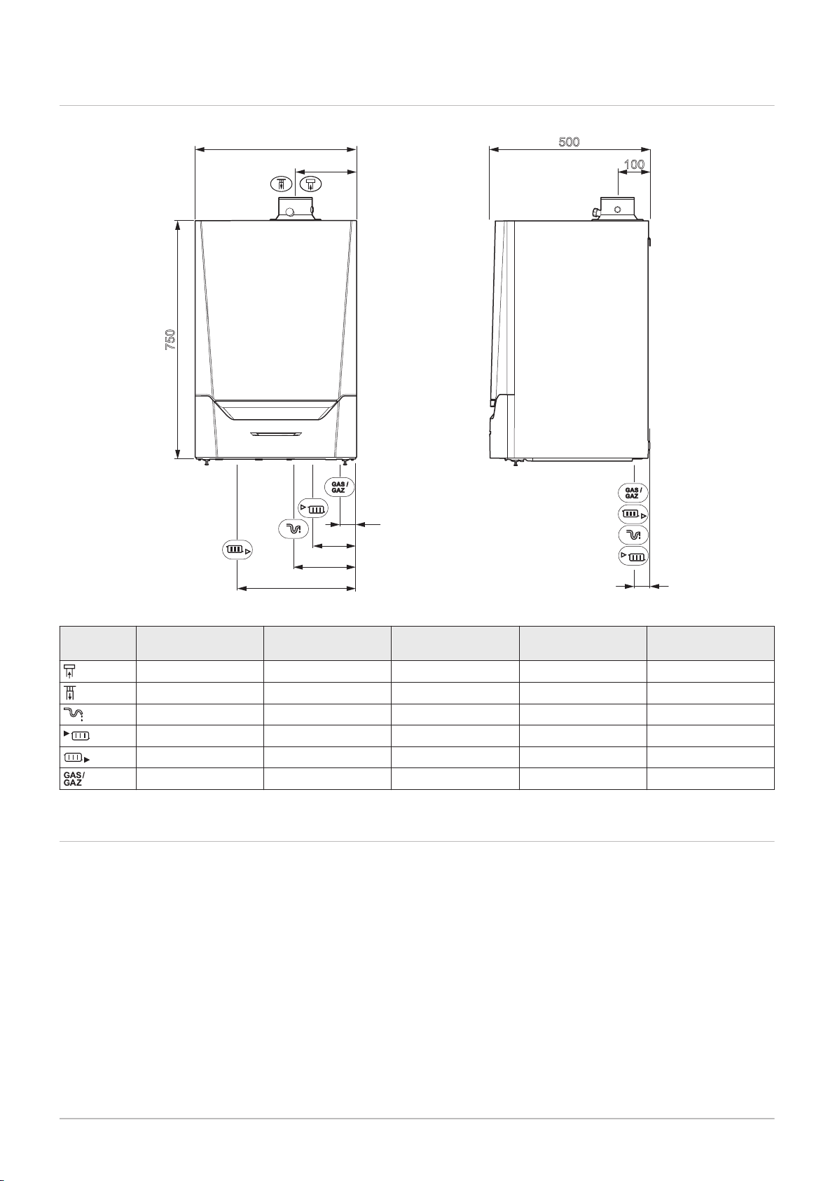
Fig.2 Dimensions
3 Description of the product
Tab.1 Connections
Symbol Connection AMC Pro
45
Flue gas outlet Ø 80 mm Ø 100 mm Ø 100 mm Ø 100 mm
Air supply Ø 125 mm Ø 150 mm Ø 150 mm Ø 150 mm
Siphon 25 mm 25 mm 25 mm 25 mm
CH flow 1 ¼" male thread 1 ¼" male thread 1 ¼" male thread 1 ¼" male thread
CH return 1 ¼" male thread 1 ¼" male thread 1 ¼" male thread 1 ¼" male thread
Gas ¾" male thread ¾" male thread ¾" male thread ¾" male thread
3.4
Introduction to the controls platform
AMC Pro
65
AMC Pro
90
AMC Pro
115
The AMC Pro boiler is equipped with the controls platform. This is a
modular system, and offers compatibility and connectivity between all
products that make use of the same platform.
Page 14
AD-3001366-01
CB
CU
B
A
C
L-Bus
SCB
MK
R-Bus
S-Bus
RU
3 Description of the product
14 AMC Pro 7725131 - v.01 - 06062019
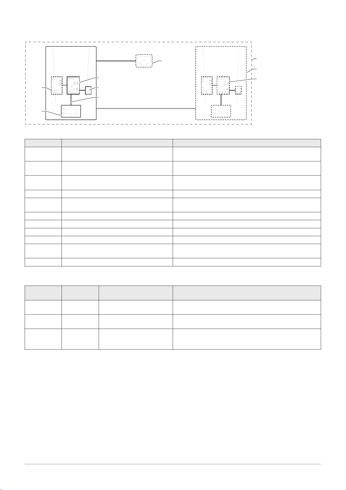
Fig.3 Generic example
Tab.2 Components in the example
Item Description Function
CU Control Unit: Control unit The control unit handles all basic functionality of the appli
ance.
CB Connection Board: Connection PCB The connection PCB is used to provide easy access to all
connectors of the control unit.
SCB Smart Control Board: Expansion PCB (option
al)
An expansion PCB can be fitted to an appliance to provide ex
tra functionality, like an internal calorifier or multiple zones.
MK Control panel: Control panel and display The control panel is the user interface to the appliance.
RU Room Unit: Room unit (e.g. a thermostat) A room unit is used to measure the temperature in a reference
room.
L-Bus Local Bus: Connection between devices The local bus provides communication between devices.
S-Bus System Bus: Connection between appliances The system bus provides communication between appliances.
R-Bus Room unit Bus: Connection to a room unit The room unit bus provides communication to a room unit.
A Device A device is a PCB, display or a room unit.
B Appliance An appliance is a set of devices connected via the same L-
Bus
C System A system is a set of appliances connected via the same S-Bus
Tab.3 Specific devices available in the AMC Pro boiler
Name visible
in display
Software ver
sion
Description Function
CU-GH08 1.7 Control unit CU-GH08 The CU-GH08 control unit handles all basic functionality of the
AMC Pro boiler.
MK3 1.29 Control panel Diematic
Evolution
The Diematic Evolution is the user interface to the AMC Pro
boiler.
SCB-10 1.03 Expansion PCB SCB-10 The SCB-10 provides functionality for one DHW and three
central heating zones, a 0-10 V connection for a PWM system
pump and potential-free contacts for status notification.
Page 15
4 Preparation of installation
AD-3001371-01
C
A
D
F
E
B
G
S2
S1
3
1
2
7725131 - v.01 - 06062019 AMC Pro 15
4.1 Installation regulations
4 Preparation of installation
Warning
The boiler must be installed by a qualified installer in accordance
with local and national regulations.
4.2
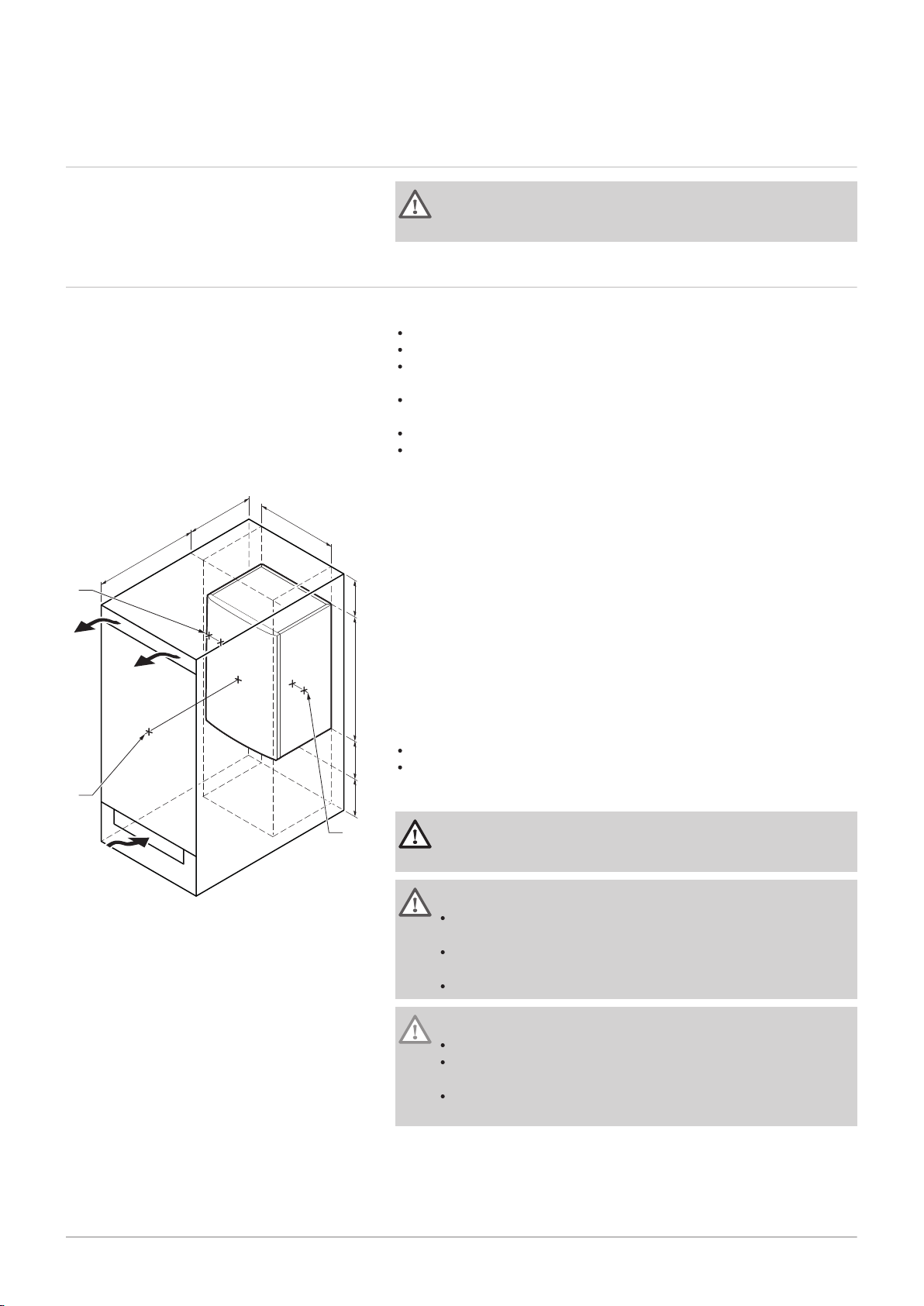
Fig.4 Installation area
Choice of the location
When choosing the best installation location, consider:
The regulations.
The required installation space.
The required space around the boiler for good access and to facilitate
maintenance.
The required space under the boiler for the installation and removal of
the siphon.
The permitted position of the flue gas outlet and/or air supply opening.
The evenness of the surface.
A
≥ 1000 mm
B
500 mm
C
500 mm
D
≥ 400 mm
E
750 mm
F
350 mm (siphon)
G
≥ 250 mm
If the boiler is installed in a closed cupboard, the minimum distance
between the boiler and the walls of the cupboard must be taken into
account.
1
≥ 1000 mm (front)
2
≥ 15 mm (left-hand side)
3
≥ 15 mm (right-hand side)
Also allow for openings to prevent the following hazards:
Accumulation of gas
Heating of the casing
Minimum cross section of the openings: S1 + S2 = 150 cm
2
Danger
It is forbidden to store, even temporarily, combustible products
and substances in the boiler or near the boiler.
Warning
Fix the appliance to a solid wall capable of bearing the weight of
the boiler when full of water and fully equipped.
Do not place the appliance above a heat source or a cooking
appliance.
Do not locate the boiler in direct or indirect sunlight.
Caution
The boiler must be installed in a frost-free area.
An earthed electrical connection must be available close to the
boiler.
A connection to the drain must be present for the condensate
drain close to the boiler.
Page 16

4 Preparation of installation
16 AMC Pro 7725131 - v.01 - 06062019
4.3 Requirements for CH water connections
When fitting service shut-off valves, position the filling and drain valve,
the expansion vessel and the safety valve between the shut-off valve
and the boiler.
Carry out any welding work required at a safe distance from the boiler or
before the boiler is fitted.
For filling and tapping the boiler, install a filling and drain valve in the
system, preferably in the return.
Install an expansion vessel in the return pipe.
4.4 Requirements for condensate drain line
The siphon must always be filled with water. This prevents flue gases
from entering the room.
Never seal the condensate drain.
The drain pipe must slope down at least 30 mm per metre, the maximum
horizontal length is 5 metres.
Condensed water must not be discharged into a gutter.
4.5
4.6
Requirements for gas connection
Before starting work on the gas pipes, turn off the main gas tap.
Before installing, check that the gas meter has sufficient capacity. Take
into account the consumption of all appliances.
Notify the local energy company if the gas meter has insufficient
capacity.
Remove dirt and dust from the gas pipe.
Always perform welding work at a sufficient distance from the boiler.
We recommend installing a gas filter to prevent clogging of the gas
valve unit.
Pipe diameters must be defined in accordance with ATG's (Association
Technique de Gaz) B171 specifications.
Requirements for the electrical connections
Establish the electrical connections in accordance with all local and
national current regulations and standards.
Electrical connections must always be made with the power supply
disconnected and only by qualified installers.
The boiler is completely pre-wired. Never change the internal
connections of the control panel.
Always connect the boiler to a well-earthed installation.
The standard NF C 15,100.
The standard CEI.
The wiring must comply with the instructions in the electrical diagrams.
Follow the recommendations in this manual.
Separate the sensor cables from the 230 V cables
Outside the boiler: Use 2 cables spaced at least 10 cm apart.
Page 17
4.7 Requirements for the flue gas outlet system
AD-3000924-01
AD-3000925-01
AD-3000926-01
7725131 - v.01 - 06062019 AMC Pro 17
4.7.1 Classification
Important
4 Preparation of installation
The installer is responsible ensuring that the right type of flue
gas outlet system is used and that the diameter and length are
correct.
Always use connection materials, roof terminal and/or outside
wall terminal supplied by the same manufacturer. Consult the
manufacturer for compatibility details.
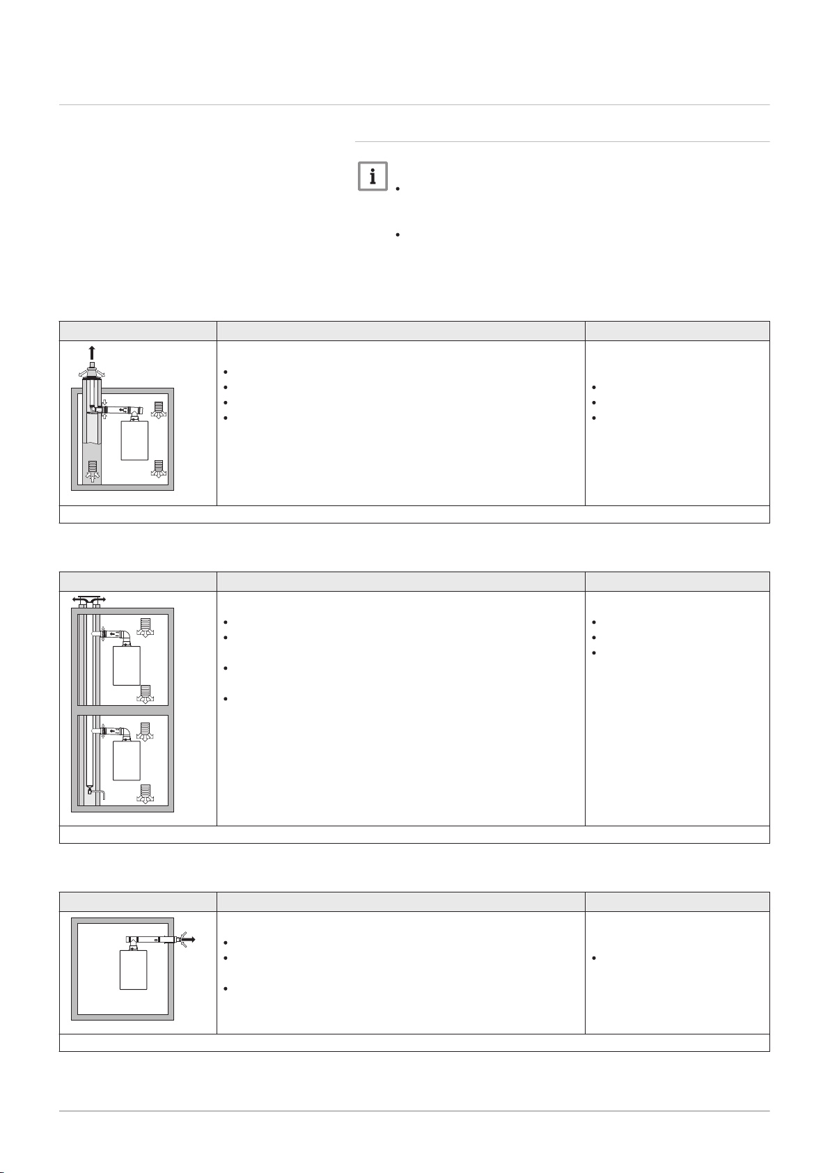
Tab.4 Type of flue gas connection: B23 - B
23P
Principle Description
Room-ventilated version
Without down-draught diverter.
Flue gas discharge via the roof.
Air from the installation area.
The IP rating of the boiler is lowered to IP20.
(1) The material must also satisfy the material property requirements from the relevant chapter.
Tab.5 Type of flue gas connection: B
33
Principle Description
Room-ventilated version
Without down-draught diverter.
Joint flue gas discharge via the roof, with guaranteed natural
draft (at all times underpressure in the joint discharge duct).
Flue gas discharge rinsed with air, air from the installation
area (special construction).
The IP rating of the boiler is lowered to IP20.
Permitted manufacturers
(1)
Connection material and roof
terminal:
Cox Geelen
Poujoulat
Ubbink
Permitted manufacturers
(1)
Connection material:
Cox Geelen
Poujoulat
Ubbink
(1) The material must also satisfy the material property requirements from the relevant chapter.
Tab.6 Type of flue gas connection: C
Principle Description
Room-sealed version
Discharge in the outside wall.
Air supply opening is in the same pressure zone as the dis
13(X)
Permitted manufacturers
Outside wall terminal and con
nection material:
Cox Geelen
charge (e.g. a combined outside wall terminal).
Parallel wall terminal not permitted.
(1) The material must also satisfy the material property requirements from the relevant chapter.
(1)
Page 18
AD-3000927-01
AD-3000929-02
4 Preparation of installation
18 AMC Pro 7725131 - v.01 - 06062019
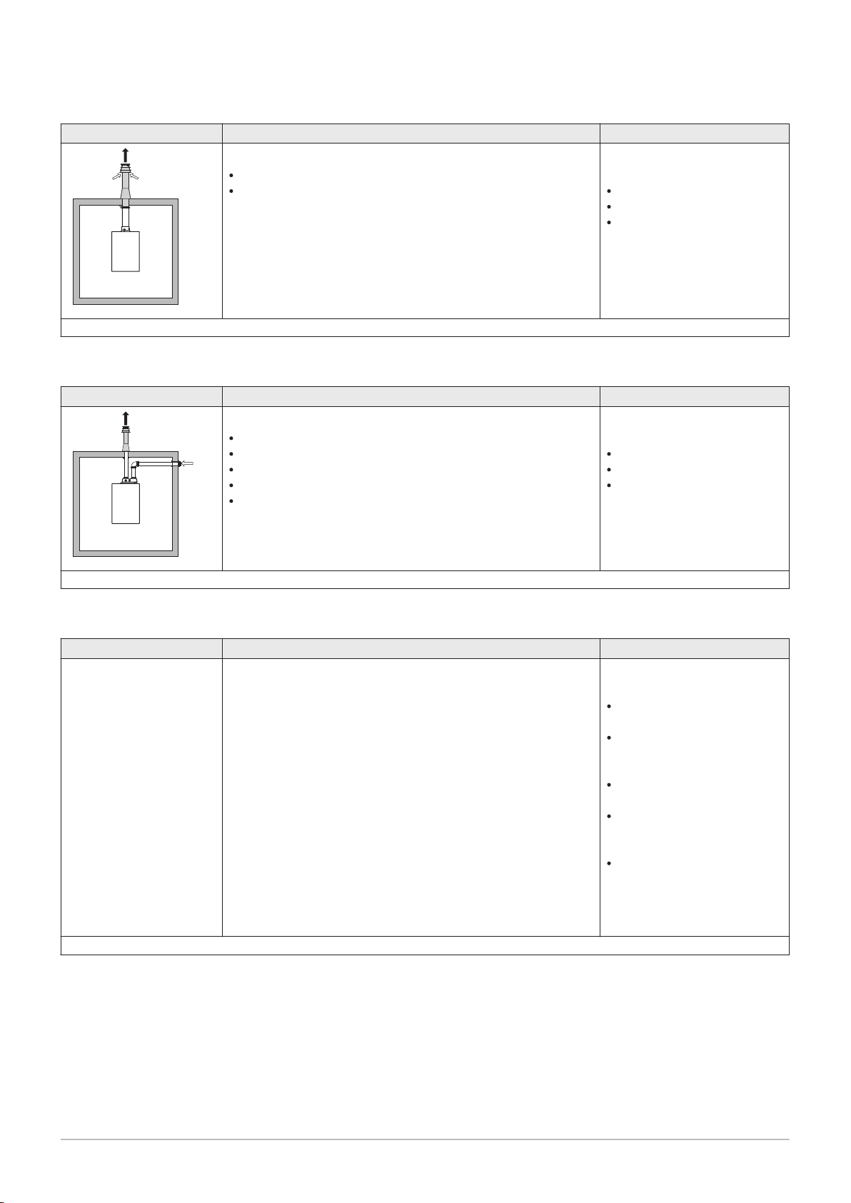
Tab.7 Type of flue gas connection: C
33(X)
Principle Description
Room-sealed version
Flue gas discharge via the roof.
Air supply opening is in the same pressure zone as the dis
charge (e.g. a concentric roof terminal).
(1) The material must also satisfy the material property requirements from the relevant chapter.
Tab.8 Type of flue gas connection: C
53
Principle Description
Connection in different pressure zones
Closed unit.
Separate air supply duct.
Separate flue gas discharge duct.
Discharging into various pressure areas.
The air supply and the flue gas outlet must not be placed on
opposite walls.
Permitted manufacturers
(1)
Roof terminal and connection
material
Cox Geelen
Poujoulat
Ubbink
Permitted manufacturers
(1)
Connection material and roof
terminal:
Cox Geelen
Poujoulat
Ubbink
(1) The material must also satisfy the material property requirements from the relevant chapter.
Tab.9 Type of flue gas connection: C
63(X)
Principle Description
This type of unit is supplied by the manufacturer without an air
supply system and flue gas system.
(1) The material must also satisfy the material property requirements from the relevant chapter.
Permitted manufacturers
(1)
When selecting the material,
please note the following:
Condensed water must flow
back to the boiler.
The material must be resist
ant to the flue gas tempera
ture of this boiler.
Maximum permissible recir
culation of 10%.
The air supply and the flue
gas outlet must not be placed
on opposite walls.
Minimum permitted pressure
difference between the air
supply and the flue gas outlet
is -200 Pa (including -100 Pa
wind pressure).
Page 19
AD-3000931-01
AD-3000330-03
□
D
Ø
D
AD-3001120-01
EN 14471 - T120 P1 W 1 O50 LI E U0
EN 1856-1 - T120 P1 W VxL40045 G(xx)
1
3
2
4
5
4 Preparation of installation
7725131 - v.01 - 06062019 AMC Pro 19
Tab.10 Type of flue gas connection: C
Principle
(1)
Description
Room-sealed version
Air supply and flue gas discharge duct in shaft or ducted:
93(X)
Concentric.
Air supply from existing duct.
Flue gas discharge via the roof.
Permitted manufacturers
Connection material and roof
terminal:
Cox Geelen
Poujoulat
Ubbink
Inlet opening for the air supply is in the same pressure zone
as the discharge.
(1) See table for shaft or duct requirements.
(2) The material must also satisfy the material property requirements from the relevant chapter.
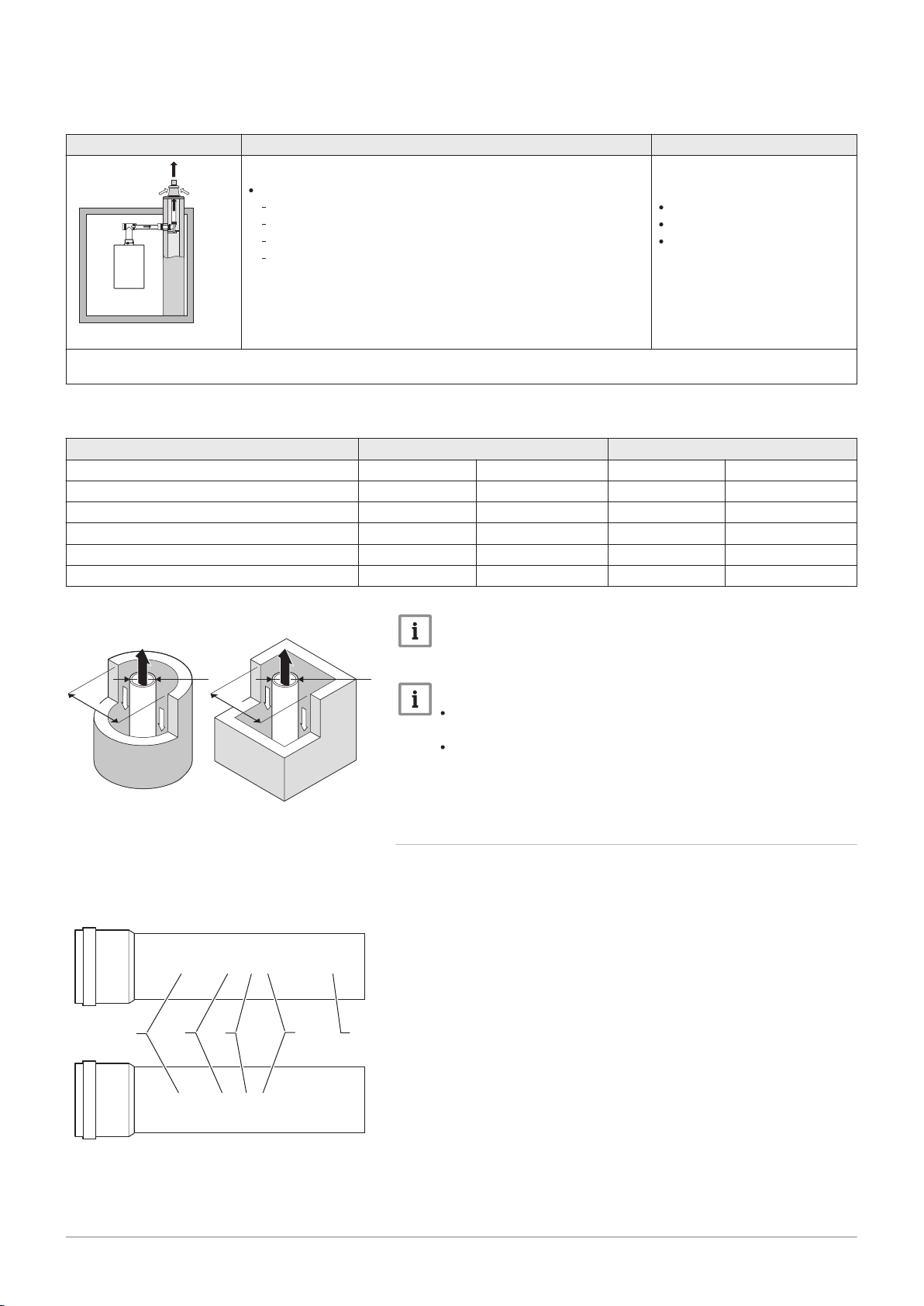
Tab.11 Minimum dimensions of shaft or duct C
93(X)
Version (D) Without air supply With air supply
Rigid 80 mm Ø 130 mm □ 130 x 130 mm Ø 140 mm □ 130 x 130 mm
Rigid 100 mm Ø 160 mm □ 160 x 160 mm Ø 170 mm □ 160 x 160 mm
Rigid 150 mm Ø 200 mm □ 200 x 200 mm Ø 220 mm □ 220 x 220 mm
Concentric 80/125 mm Ø 145 mm □ 145 x 145 mm Ø 145 mm □ 145 x 145 mm
Concentric 100/150 mm Ø 170 mm □ 170 x 170 mm Ø 170 mm □ 170 x 170 mm
Concentric 150/200 mm Ø 270 mm □ 270 x 270 mm - -
(2)
Fig.5 Minimum dimensions of shaft or
duct C
93(X)
Fig.6 Sample string
Important
The shaft must comply with the air density requirements of the
local regulations.
Important
Always clean shafts thoroughly when using lining pipes and/or
an air supply connection.
It must be possible to inspect the lining duct.
4.7.2 Material
Use the string on the flue gas outlet material to check whether it is suitable
for use on this appliance.
1
EN 14471 of EN 1856–1: The material is CE approved according to
this standard. For plastic this is EN 14471, For aluminium and
stainless steel this is EN 1856-1.
2
T120: The material has temperature class T120. A higher number
is also allowed, but not lower.
3
P1: The material falls into pressure class P1. H1 is also allowed.
4
W: The material is suitable for draining condensation water
(W=’wet’). D is not allowed (D=’dry’).
5
E: The material falls into fire resistance class E. Class A to D are
also allowed, F is not allowed. Only applicable to plastic.
Page 20
AD-3001094-01
ød
1
AD-3000963-01
ød
1
øD
1
4 Preparation of installation
20 AMC Pro 7725131 - v.01 - 06062019
Warning
The coupling and connection methods may vary depending on
the manufacturer. It is not permitted to combine pipes, coupling
and connection methods from different manufacturers. This also
applies to roof feed-throughs and common channels.
The materials used must comply with the prevailing regulations
and standards.
Tab.12 Overview of material properties
Version Flue gas outlet Air supply
Material Material properties Material Material properties
Single-wall, rigid
(1)
Plastic
Stainless steel
Thick-walled,
aluminium
(2)
With CE marking
(2)
Temperature class T120 or
higher
Condensate class W (wet)
Plastic
Stainless steel
Aluminium
Pressure class P1 or H1
Fire resistance class E or bet
(3)
ter
(1) according to EN 14471
(2) according to EN 1856
(3) according to EN 13501-1
With CE marking
Pressure class P1 or H1
Fire resistance class E or bet
(3)
ter
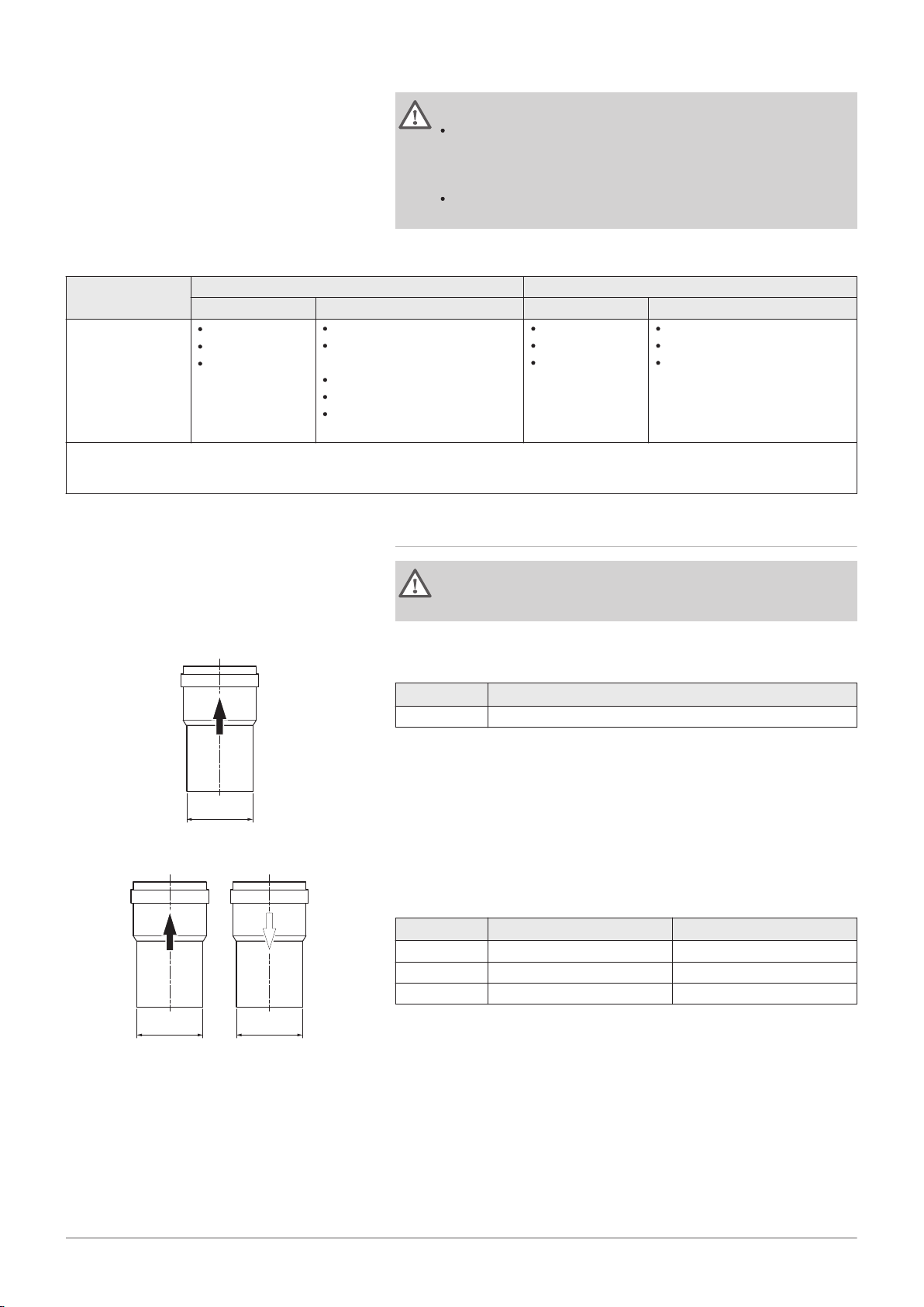
Fig.7 Dimensions of open connection
Fig.8 Dimensions of parallel connection
4.7.3 Dimensions of flue gas outlet pipe
Warning
The pipes connected to the flue gas adapter must satisfy the
following dimension requirements.
d
External dimensions of flue gas outlet pipe
1
Tab.13 Dimensions of pipe
d1 (min-max)
150 mm 149 - 151 mm
d
External dimensions of flue gas outlet pipe
1
D
External dimensions of air supply pipe
1
Tab.14 Dimensions of pipe
d1 (min-max) D1 (min-max)
80/80 mm 79.3 - 80.3 mm 79.3 - 80.3 mm
100/100 mm 99.3 - 100.3 mm 99.3 - 100.3 mm
150/150 mm 149 - 151 mm 149 - 151 mm
Page 21
AD-3000962-01
ød
1
L
1
øD
1
AD-0000028-02
L =
4 Preparation of installation
7725131 - v.01 - 06062019 AMC Pro 21
Fig.9 Dimensions of concentric
connection
d
External dimensions of flue gas outlet pipe
1
D
External dimensions of air supply pipe
1
L
Length difference between flue gas outlet pipe and air supply pipe
1
Tab.15 Dimensions of pipe
d1 (min-max) D1 (min-max)
(1)
L
(min-max)
1
80/125 mm 79.3 - 80.3 mm 124 - 125.5 mm 0 - 15 mm
100/150 mm 99.3 - 100.3 mm 149 - 151 mm 0 - 15 mm
(1) Shorten the inner pipe if the length difference is too great.
4.7.4 Length of the air and flue gas pipes
The maximum length of the flue gas outlet and air supply channel vary
depending on the appliance type; consult the relevant chapter for the
correct lengths.
Important
When using bends, the maximum chimney length (L) must be
shortened according to the reduction table.
For adaptation to another diameter use approved transitions
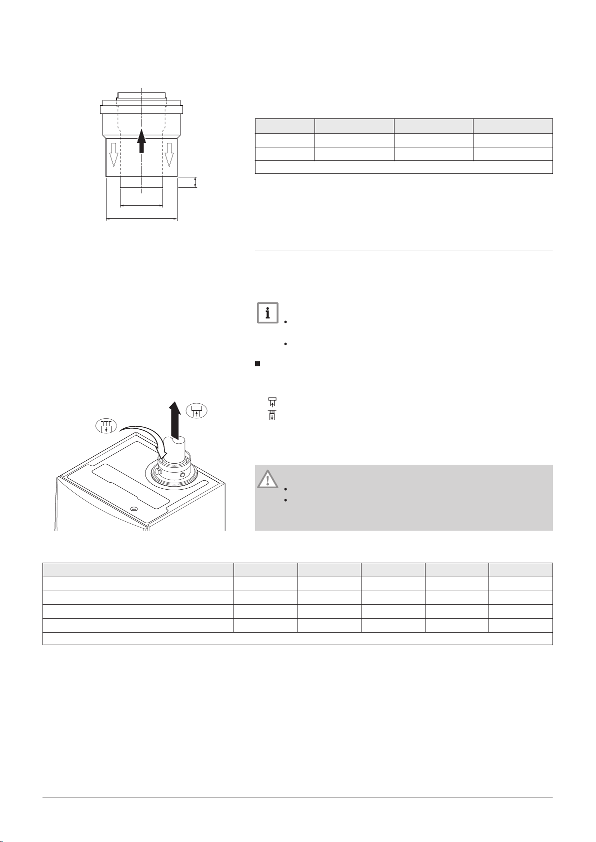
Fig.10 Room-ventilated version
Room-ventilated model (B23, B
L
Length of the flue gas outlet channel to roof feed-through
23P
, B33)
Connecting the flue gas outlet
Connecting the air supply
With a room-ventilated version, the air supply opening stays open; only the
flue gas outlet opening is connected. This will ensure that the boiler
obtains the necessary combustion air directly from the installation area.
Caution
The air supply opening must stay open.
The installation area must be equipped with the necessary air
supply openings. These openings must not be obstructed or
shut off.
Tab.16 Maximum length (L)
Diameter
(1)
AMC Pro 45 39 m
80 mm 90 mm 100 mm 110 mm 130 mm
40 m
(1)
40 m
(1)
40 m
AMC Pro 65 11 m 17 m 26 m 40 m
AMC Pro 90 10 m 16 m 24 m 40 m
AMC Pro 115 8 m 13 m 19 m 38 m
(1) Retaining the maximum chimney length it is possible to use an extra 5 x 90º or 10 x 45º elbows.
(1)
40 m
40 m
40 m
40 m
(1)
(1)
(1)
(1)
Page 22
AD-0000027-02
L = +
AD-0000029-02
L =
4 Preparation of installation
22 AMC Pro 7725131 - v.01 - 06062019
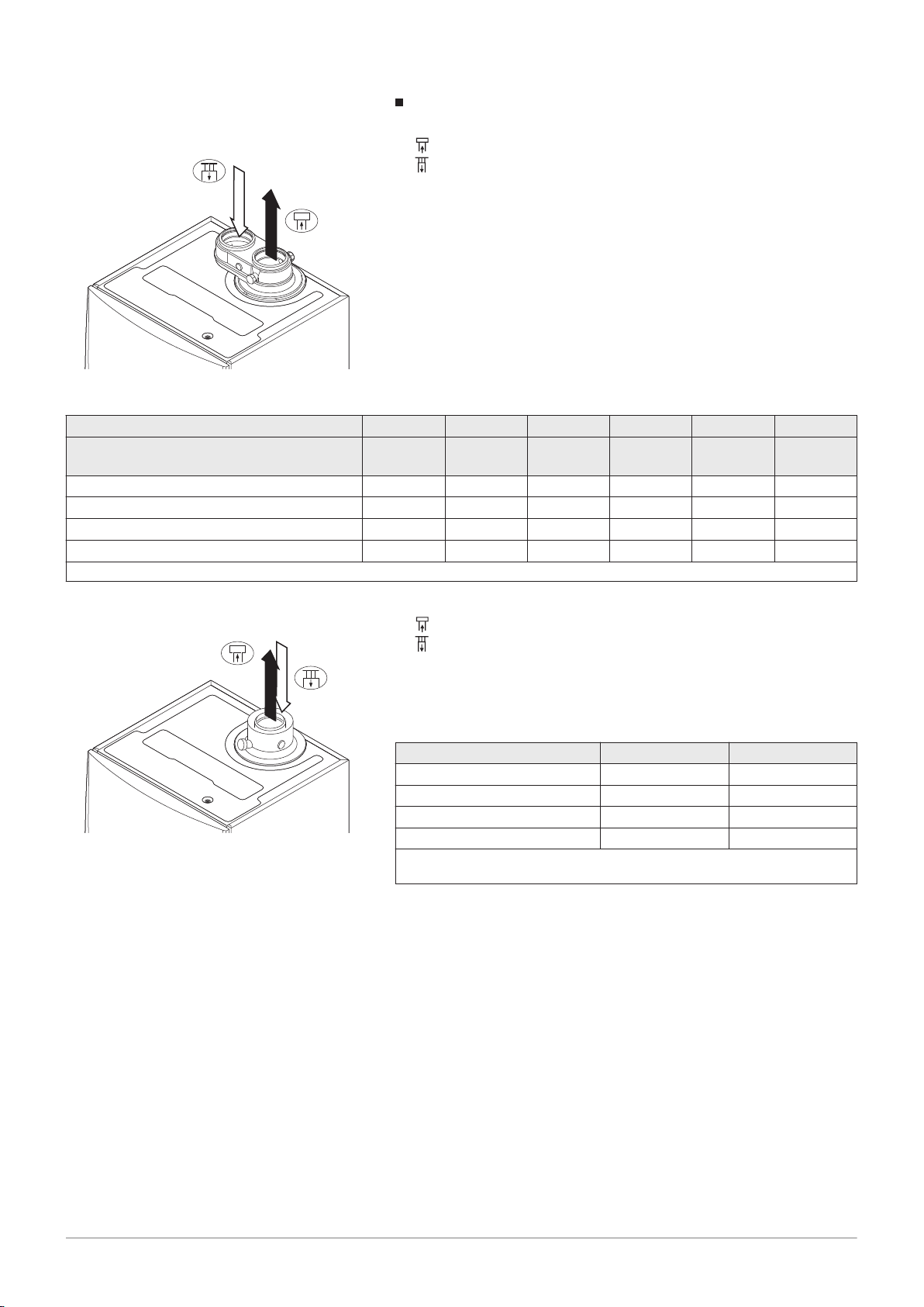
Fig.11 Room-sealed version (parallel)
Room-sealed model (C
Connecting the flue gas outlet
13(X)
, C
33(X)
, C
63(X)
, C
93(X)
)
Connecting the air supply
With a room-sealed version, both the flue gas outlet and the air supply
openings are connected (in parallel).
Tab.17 Maximum length (L)
Pipe diameter
(1)
80 mm 90 mm 100 mm 110 mm 110 mm 130 mm
Diameter of concentric roof terminal 80/125 mm 80/125 mm 100/150 mm100/150 mm130/180 mm130/180
mm
AMC Pro 45 34 m
40 m
(1)
AMC Pro 65 2 m 14 m 20 m 34 m 40 m
AMC Pro 90 - 12 m 16 m 30 m 40 m
AMC Pro 115 - 4 m 12 m 20 m 40 m
(1) Retaining the maximum chimney length it is possible to use an extra 5 x 90º or 10 x 45º elbows.
40 m
(1)
40 m
(1)
40 m
(1)
40 m
40 m
40 m
40 m
(1)
(1)
(1)
(1)
Fig.12 Room-sealed version (concentric)
Connecting the flue gas outlet
Connecting the air supply
With a room-sealed version, both the flue gas outlet and the air supply
openings are connected (concentrically).
Tab.18 Maximum chimney length (L)
Diameter
(1)
AMC Pro 45 20 m
80/125 mm 100/150 mm
(1)
20 m
AMC Pro 65 4 m 18 m
AMC Pro 90 4 m 17 m
AMC Pro 115 - 13 m
(1) Retaining the maximum chimney length it is possible to use an extra 5 x 90º
or 10 x 45º elbows.
Page 23
AD-0000030-02
= L +
4 Preparation of installation
7725131 - v.01 - 06062019 AMC Pro 23
Connection in different pressure areas (C53)
Fig.13
Different pressure areas
L
Total length of the flue gas outlet and air supply duct
Connecting the flue gas outlet
Connecting the air supply
An 80/80 or 100/100 mm flue gas adapter (accessory) must be fitted for
this connection.
Combustion air supply and flue gas discharge are possible in different
pressure areas and semi-CLV systems, with the exception of the coastal
area. The maximum permitted height difference between the combustion
air supply and the flue gas outlet is 36 m.
Tab.19 Maximum length (L)
Diameter
(1)
AMC Pro 45 29 m 40 m
80 mm 90 mm 100 mm 110 mm 130 mm
(1)
40 m
40 m
AMC Pro 65 5 m 10 m 16 m 34 m
AMC Pro 90 - - 17 m 37 m
AMC Pro 115 - - 14 m 31 m
(1) Retaining the maximum chimney length it is possible to use an extra 5 x 90º or 10 x 45º elbows.
(1)
40 m
40 m
40 m
40 m
(1)
(1)
(1)
(1)
Reduction table
Tab.20 Pipe reduction for each element used (parallel)
Diameter 80 mm 100 mm
45° bend 1.2 m 1.4 m
90° bend 4.0 m 4.9 m
Tab.21 Pipe reduction for each element used (concentric)
Diameter 80/125 mm 100/150 mm
45° bend 1.0 m 1.0 m
90° bend 2.0 m 2.0 m
4.7.5 Additional guidelines
Installation
For installing the flue gas outlet and air supply materials, refer to the
instructions of the manufacturer of the relevant material. After
installation, check at least all flue gas outlet and air supply parts for
tightness.
Warning
If the flue gas outlet and air supply materials are not installed in
accordance with the instructions (e.g. not leak-proof, not correctly
bracketed), this can result in dangerous situations and/or physical
injury.
Make sure that the flue gas outlet pipe towards the boiler has a sufficient
gradient (at least 50 mm per metre) and that there is a sufficient
condensate collector and discharge (at least 1 m before the outlet of the
boiler). The bends used must be larger than 90° to guarantee the
gradient and a good seal on the lip rings.
Page 24

4 Preparation of installation
24 AMC Pro 7725131 - v.01 - 06062019
Condensation
Direct connection of the flue gas outlet to structural ducts is not
permitted because of condensation.
If condensate from a plastic or stainless steel pipe section can flow back
to an aluminium part in the flue gas outlet, this condensate must be
discharged via a collector before it reaches the aluminium.
Newly installed aluminium flue gas pipes with longer lengths can
produce relatively larger quantities of corrosion products. Check and
clean the siphon more often in this case.
Important
Contact us for more information.
4.8
Water quality and water treatment
4.9 Process heat application
The quality of the CH water must comply with certain limit values, which
can be found in our Water quality instructions. The guidelines in these
instructions must be followed at all times.
In many cases, the boiler and central heating system can be filled with
normal tap water and water treatment will not be necessary.
In process heat applications (for example pasteurisation and drying and
washing processes), the boiler is being used for industrial purposes and
not for central heating. With process heat, the nominal flow (at ΔT 20°C) in
the primary CH circuit must be guaranteed. The flow in the secondary
circuit may vary.
To ensure that this is the case, a flow rate sensor can be fitted, which
locks out the boiler if the flow falls below a specified level (due to a
defective pump or valve, for example).
Important
The service life of the boiler may be reduced if it is used for
process heat applications.
For more information, see
Setting for process heat application, page 60
4.10 Increase default ΔT setting
In some cases, the default ΔT setting of the boiler will need to be
increased, for example in systems with:
underfloor heating
air heating
district heating
a heat pump.
Important
Prevent the boiler from locking out and ensure a minimal water
circulation by using a bypass or low-loss header.
For more information, see
Changing the default ΔT setting, page 61
Page 25
4.11 Installation examples
7725131 - v.01 - 06062019 AMC Pro 25
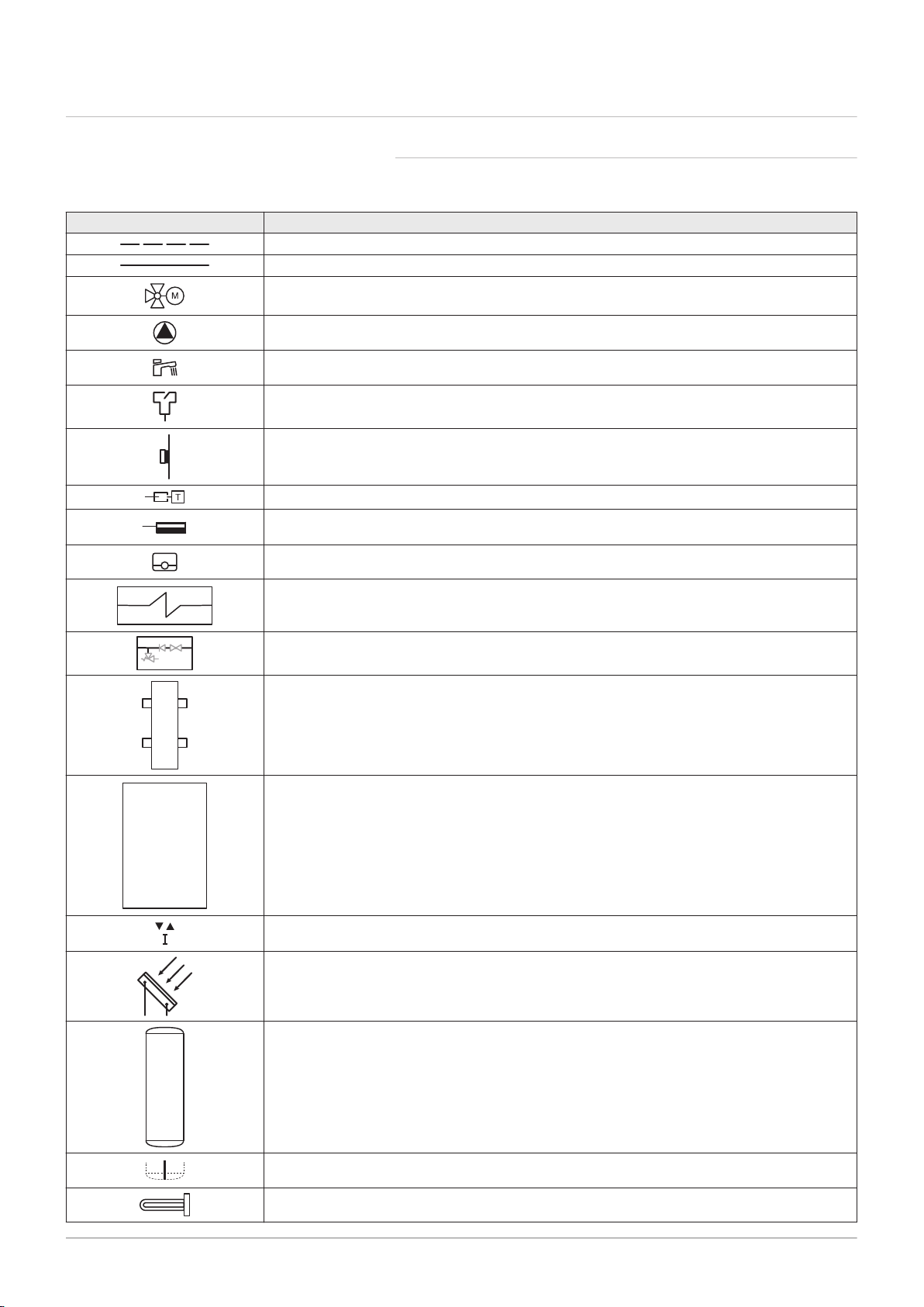
4.11.1 Symbols used
Tab.22 Explanation of symbols in the hydraulics flow diagram
Symbol Explanation
Return pipe
Flow pipe
Mixing valve
Pump
Domestic hot water
Make contact
Outdoor temperature sensor
Sensor
Safety thermostat
4 Preparation of installation
Room thermostat
Plate heat exchanger
Safety group
Low-loss header
Instant boiler
Primary heating circuit connection
Solar collector
Domestic hot water storage tank
Titanium anode
(1)
Electrical heating element
Page 26
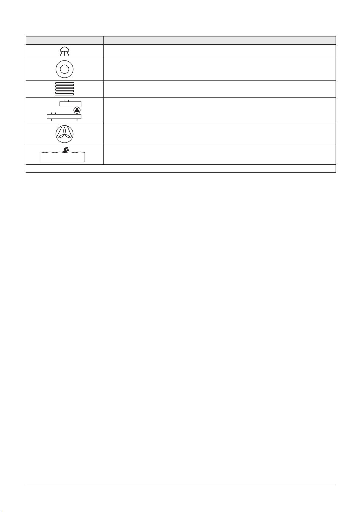
4 Preparation of installation
26 AMC Pro 7725131 - v.01 - 06062019
Symbol Explanation
Shower
Heating zone
Underfloor heating
Underfloor heating manifold
Hot-air heater
Swimming pool
(1) Fitted in domestic hot water storage tank.
Page 27
4.11.2 Connection example 4
AD-4100037-01
1
A
M
6
T
4
5
C
3
2
B
7
9
D
10
8
AD-4100139-01
6.3A T
X12
X13
X15
S-BUS
X1
X9
X11
X2
X3
X4
X5
X10
RS
SP
L-BUS
SCB-10
X14
+TA-
TA
1 2 C B A
Tsyst Tsyst Tdhw Tflow Tflow Tflow
X8
N L
X14
N L
B
C
N
N L
TS
N L
A
N
TS
T out
Status
R-Bus
12
3
4
+
0-10V
-
C
R-BusBR-Bus
A
N L
TS
N
R-Bus
Tout
BL
RL
Tdhw
CB-03
X131 X136
X4
X03
42359 6
108
A
1
7
7725131 - v.01 - 06062019 AMC Pro 27
Fig.14 1 boiler + 1 direct zone + 1 mixing zone + domestic hot water (DHW) zone
4 Preparation of installation
C
Mixing zone - CircB1 (underfloor heating)
D
DHW zone - DHWA (layered calorifier - 2 sensors)
A
Boiler
B
Direct zone - CircA1
Important
For this configuration an additional PCB (accessory AD249) is placed on connector X8 of the SCB-10 PCB.
Page 28

4 Preparation of installation
28 AMC Pro 7725131 - v.01 - 06062019
Tab.23
On > > Installation Setup > SCB-10 > DHWA > Parameters, counters, signals > Parameters
Code Display text Description Range Setting
CP022 Zone Function Functionality of the zone 0 = Disable
10
1 = Direct
2 = Mixing Circuit
3 = Swimming pool
4 = High Temperature
5 = Fan Convector
6 = DHW tank
7 = Electrical DHW
8 = Time Program
9 = ProcessHeat
10 = DHW Layered
11 = DHW Internal tank
31 = DHW FWS EXT
Tab.24
On > > Installation Setup > SCB-10 > AUX > Parameters, counters, signals > Parameters
Code Display text Description Range Setting
CP024 Zone Function Functionality of the zone 0 = Disable
8
1 = Direct
2 = Mixing Circuit
3 = Swimming pool
4 = High Temperature
5 = Fan Convector
6 = DHW tank
7 = Electrical DHW
8 = Time Program
9 = ProcessHeat
10 = DHW Layered
11 = DHW Internal tank
31 = DHW FWS EXT
Page 29

AD-4100039-01
1
A
9
8
E
7
D
6
C
M
5
T
3
4
B
2
10
12
F
13
11
AD-4100141-01
R-Bus
Tout
BL
RL
Tdhw
CB-03
X131 X136
X4
X03
6.3A T
X12
X13
X15
S-BUS
X1
X9 X11
X2 X3
X4
X5
X10
RS
SP
L-BUS
SCB-10
X14
N
L
B
C
N
N L
A
N
TS
N L
TS
R-Bus
T out
Status
R-Bus
R-Bus
1C2
3
4
+
0-10V
-
B
A
+TA-
TA
1 2 C B A
Tsyst Tsyst Tdhw Tflow Tflow Tflow
X8
N L
X14
N L
TS
N
362412 5
13 711
1
1098
A
4 Preparation of installation
7725131 - v.01 - 06062019 AMC Pro 29
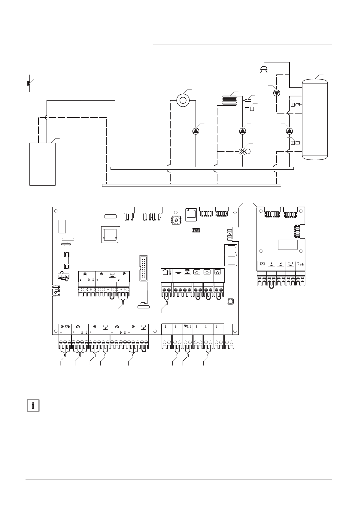
4.11.3 Connection example 6
Fig.15 1 boiler + 1 mixing zone + 1 direct zone + swimming pool zone + domestic hot water (DHW) zone
D
Direct zone - CircC1 (swimming pool)
E
Plate heat exchanger
F
DHW zone - DHWA (layered calorifier - 2 sensors)
A
Boiler
B
Mixing zone - CircB1 (underfloor heating)
C
Direct zone - CircA1 (fan convector)
Important
For this configuration an additional PCB (accessory AD249) is placed on connector X8 of the SCB-10 PCB.
Page 30

4 Preparation of installation
30 AMC Pro 7725131 - v.01 - 06062019
Tab.25
On > > Installation Setup > SCB-10 > CIRCA1> Parameters, counters, signals > Parameters
Code Display text Description Range Setting
CP020 Zone Function Functionality of the zone 0 = Disable
5
1 = Direct
2 = Mixing Circuit
3 = Swimming pool
4 = High Temperature
5 = Fan Convector
6 = DHW tank
7 = Electrical DHW
8 = Time Program
9 = ProcessHeat
10 = DHW Layered
11 = DHW Internal tank
31 = DHW FWS EXT
Tab.26
On > > Installation Setup > SCB-10 > CIRCC1 > Parameters, counters, signals > Parameters
Code Display text Description Range Setting
CP023 Zone Function Functionality of the zone 0 = Disable
3
1 = Direct
2 = Mixing Circuit
3 = Swimming pool
4 = High Temperature
5 = Fan Convector
6 = DHW tank
7 = Electrical DHW
8 = Time Program
9 = ProcessHeat
10 = DHW Layered
11 = DHW Internal tank
31 = DHW FWS EXT
Tab.27
On > > Installation Setup > SCB-10 > DHWA > Parameters, counters, signals > Parameters
Code Display text Description Range Setting
CP022 Zone Function Functionality of the zone 0 = Disable
10
1 = Direct
2 = Mixing Circuit
3 = Swimming pool
4 = High Temperature
5 = Fan Convector
6 = DHW tank
7 = Electrical DHW
8 = Time Program
9 = ProcessHeat
10 = DHW Layered
11 = DHW Internal tank
31 = DHW FWS EXT
Page 31

4 Preparation of installation
7725131 - v.01 - 06062019 AMC Pro 31
Tab.28
On > > Installation Setup > SCB-10 > AUX > Parameters, counters, signals > Parameters
Code Display text Description Range Setting
CP024 Zone Function Functionality of the zone 0 = Disable
8
1 = Direct
2 = Mixing Circuit
3 = Swimming pool
4 = High Temperature
5 = Fan Convector
6 = DHW tank
7 = Electrical DHW
8 = Time Program
9 = ProcessHeat
10 = DHW Layered
11 = DHW Internal tank
31 = DHW FWS EXT
Page 32

AD-4100044-01
1
C
B
3
A
2
4
12
11
13
F
9
8
10
E
6
5
7
D
14
16
G
18
17
15
AD-4100146-01
6.3A T
X12
X13
X15
S-BUS
X1
X9
X11
X2
X1
X3 X4
X2
X3
X4
X5
X10
RS
SP
L-BUS
SCB-10
X14
N L
X8
X14
N LBN
N L TS
N L
A
N
TS
T out
Status
R-Bus
1
2
3
4
+
0-10V
-
C
R-BusBR-Bus
A
+TA-
TA
1 2 C B A
Tsyst Tsyst Tdhw Tflow Tflow Tflow
N L
TS
N
C
R-Bus
Tout
BL
RL
Tdhw
CB-03
X131 X136
X4
X03
GTW-25
8 5 18
11
171549 610
13
716
A
A–B
1
14
12
4 Preparation of installation
32 AMC Pro 7725131 - v.01 - 06062019
4.11.4 Connection example 16
Fig.16 2 boiler cascade + low-loss header + 3 mixing zones + domestic hot water (DHW) zone
A-B
S-BUS cable (comes with 2 resistors; one on
connector X5 on the SCB-10 and one on connector
X4 on the GTW-25 PCB from boiler B)
2
Pump connection via cables X81 and X112, which
can be found in boiler A's instrument box
3
Pump connection via cables X81 and X112, which
can be found in boiler B's instrument box
A
Boiler (master)
B
Boiler (slave)
C
Low-loss header
D
Mixing zone - CircA1
E
Mixing zone - CircB1
F
Mixing zone - CircC1
G
DHW zone - DHWA (layered calorifier - 2 sensors)
Important
For this configuration an additional PCB (accessory AD249) is placed on connector X8 of the SCB-10.
Page 33

4 Preparation of installation
7725131 - v.01 - 06062019 AMC Pro 33
Tab.29 Installation Setup > SCB-10 > CIRCA1 > Parameters, counters, signals > Parameters
Code Display text Description Range Setting
CP000 MaxZoneTFlowSetpoint Maximum Flow Temperature setpoint
7 °C – 100 °C 50
zone
CP010 Tflow setpoint zone Zone flow temperature setpoint, used
7 °C – 100 °C 40
when the zone is set to a fixed flow
setpoint.
CP020 Zone Function Functionality of the zone 0 = Disable
2
1 = Direct
2 = Mixing Circuit
3 = Swimming pool
4 = High Temperature
5 = Fan Convector
6 = DHW tank
7 = Electrical DHW
8 = Time Program
9 = ProcessHeat
10 = DHW Layered
11 = DHW Internal tank
31 = DHW FWS EXT
CP230 Zone Heating Curve Heating curve temperature gradient of
0 – 4 0.7
the zone
Tab.30 Installation Setup > SCB-10 > DHWA > Parameters, counters, signals > Parameters
Code Display text Description Range Setting
CP022 Zone Function Functionality of the zone 0 = Disable
10
1 = Direct
2 = Mixing Circuit
3 = Swimming pool
4 = High Temperature
5 = Fan Convector
6 = DHW tank
7 = Electrical DHW
8 = Time Program
9 = ProcessHeat
10 = DHW Layered
11 = DHW Internal tank
31 = DHW FWS EXT
Tab.31 Installation Setup > SCB-10 > AUX > Parameters, counters, signals > Parameters
Code Display text Description Range Setting
CP024 Zone Function Functionality of the zone 0 = Disable
8
1 = Direct
2 = Mixing Circuit
3 = Swimming pool
4 = High Temperature
5 = Fan Convector
6 = DHW tank
7 = Electrical DHW
8 = Time Program
9 = ProcessHeat
10 = DHW Layered
11 = DHW Internal tank
31 = DHW FWS EXT
Tab.32 Installation Setup > SCB-10 > Cascade management B > Parameters, counters, signals > Parameters
Code Display text Description Range Setting
AP083 Enable master func Enable the master functionality of this
device on the S-Bus for system control
0 = No
1 = Yes
1
Page 34

4 Preparation of installation
34 AMC Pro 7725131 - v.01 - 06062019
Tab.33 Installation Setup > SCB-10 > Analogue input > Parameters, counters, signals > Adv. Parameters
Code Display text Description Range Setting
EP036 Sensor input config Sets the general configuration of the
sensor input
0 = Disabled
1 = DHW tank
2
2 = DHW tank top
3 = Buffer tank sensor
4 = Buffer Tank top
5 = System (cascade)
EP037 Sensor input config Sets the general configuration of the
sensor input
0 = Disabled
1 = DHW tank
3
2 = DHW tank top
3 = Buffer tank sensor
4 = Buffer Tank top
5 = System (cascade)
Page 35

5 Installation
MW-3000014-2
AD-0000018-02
2
1
5
4
3
7725131 - v.01 - 06062019 AMC Pro 35
5.1 Positioning the boiler
5 Installation
Fig.17 Mounting the boiler
The fitting bracket on the back of the casing can be used to mount the
boiler directly on the suspension bracket.
The boiler is supplied with a mounting template.
1. Attach the mounting template of the boiler to the wall using adhesive
tape.
Warning
Use a level to check whether the mounting template is hanging
perfectly horizontally.
Protect the boiler against building dust and cover the connection
points for the flue gas outlet and air supply. Only remove this
cover to assemble the relevant connections.
2. Drill 2 holes of Ø 10 mm.
Important
The extra fixing holes in the suspension bracket are intended for
use in the event that one of the two holes is not suitable for the
correct fastening of the plug.
3. Fit the Ø 10 mm plugs.
4. Remove the mounting template.
5. Attach the suspension bracket to the wall with the Ø 10 mm bolts
supplied.
6. Mount the boiler on the suspension bracket.
5.2 Mounting an outdoor sensor
Fig.18
5.2.1 Positions to be avoided
Avoid placing the outside sensor in a position with the following
characteristics:
Masked by part of the building (balcony, roof, etc.).
Close to a disruptive heat source (sun, chimney, ventilation grid, etc.).
5.2.2 Recommended positions
Place the outside sensor in a position that covers the following
characteristics:
On a façade of the area to be heated, on the north if possible.
Half way up the wall of the area to be heated.
Under the influence of changes in the weather.
Protected from direct sunlight.
Easy to access.
Page 36

MW-8800N001-3
2
1
2
1
1
2
H
1/2 H (min. 2,5 m)
1/2 H (min. 2,5 m)
1/2 Z
H
Z
MW-8800N003-6
2
3
4
5 Installation
36 AMC Pro 7725131 - v.01 - 06062019
Fig.19
1
Optimum location
2
Possible position
Fig.20
5.3 Rinsing the system
H
Inhabited height controlled by the sensor
Z
Inhabited area controlled by the sensor
5.2.3 Fitting the outdoor sensor
1. Choose a recommended location for the outdoor sensor.
2. Put the 2 plugs in place, delivered with the sensor.
Plugs diameter 4 mm/drill diameter 6 mm
3. Secure the sensor using the screws provided (diameter 4 mm).
4. Connect the cable to the outdoor temperature sensor.
Installation must be carried out in accordance with the prevailing
regulations, codes of practice and the recommendations in this manual.
Before a new boiler can be connected to an existing or new system, the
entire system must be thoroughly cleaned and flushed. This step is
absolutely crucial. The flushing helps to remove residue from the
installation process (weld slag, fixing products etc.) and accumulations of
dirt (silt, mud etc.)
Important
Flush the system with a volume of water equivalent to at least
three times the volume of the system.
Flush the DHW pipes with at least 20 times the volume of the
pipes.
Page 37

5.4 Connecting the heating circuit
AD-4100110-01
1
2
4
5
4
3
AD-0000024-02
4
1
2
3
7725131 - v.01 - 06062019 AMC Pro 37
5 Installation
Fig.21 Connecting the CH flow and CH
return
1. Remove the dust cap from the CH flow connection at the bottom
of the boiler.
2. Fit the outlet pipe for CH water to the CH flow connection.
3. Remove the dust cap from the CH return connection at the
bottom of the boiler.
4. Fit the inlet pipe for CH water to the CH return connection.
5. Install the pump in the CH return pipe.
For more information, see
Connecting the PWM pump, page 47
Connecting the standard pump, page 46
5.5 Connecting the condensate discharge pipe
Fig.22 Connecting the condensate
discharge pipe
1. Fit a plastic drain pipe of Ø 32 mm or larger, terminating in the drain.
2. Insert the flexible condensate drain hose into the pipe.
3. Fit a stench-trap or siphon in the drain pipe.
4. Fit the siphon.
Page 38

AD-0000025-02
2
3
4
1
AD-0000034-01
80/125 mm
100/150 mm
S
AD-3001374-01
5 Installation
38 AMC Pro 7725131 - v.01 - 06062019
5.6 Gas connection
Fig.23 Connecting the gas pipe
5.7
Air supply/flue gas outlet connections
Fig.24 Connecting the flue gas outlet and
air supply
1. Remove the dust cap from the gas supply pipe at the bottom of
the boiler.
2. Fit the gas supply pipe.
3. Fit a gas tap in this pipe, directly underneath the boiler (within 1
metre).
4. Fit the gas pipe to the gas tap.
Important
The gas tap must always be accessible
5.7.1 Connecting the flue gas outlet and air supply
S Insertion depth 25 mm
1. Connect the flue gas outlet pipe and the air supply pipe to the boiler.
2. Fit the subsequent flue gas outlet pipes and air supply pipes in
accordance with the manufacturer's instructions.
5.8 Electrical connections
Fig.25 CU-GH08
Caution
The pipes must not be resting on the boiler.
Fit the horizontal parts sloping down towards the boiler, with a
gradient of 50 mm per metre.
5.8.1 Control unit
The table gives important connection values for the control unit.
Tab.34 Connection values for control unit
Supply voltage 230 VAC/50 Hz
Main fuse value F1 (230 VAC) 2.5 AT
Fan 230 VAC
Page 39

AD-3001411-01
3
2
2
1
90 º
AD-3001412-01
5
4
AD-3001414-01
6
9
8
7
10
5 Installation
7725131 - v.01 - 06062019 AMC Pro 39
Danger of electric shock
The following components of the boiler are connected to a 230 V
power supply:
Electrical connection to circulating pump.
Electrical connection to gas combination block.
Electrical connection to fan.
Control unit.
Ignition transformer.
Power supply cable connection.
The boiler has a three-wire mains lead (lead length 1.5 m) and is suitable
for a 230 VAC/50 Hz power supply with a phase/neutral/earth system. The
boiler is not phase sensitive. The power supply cable is connected to the
X1 connector. A spare fuse can be found in the housing of the control unit.
The boiler has several control, protection and regulation connection
options. The standard PCB can be extended with optional PCBs.
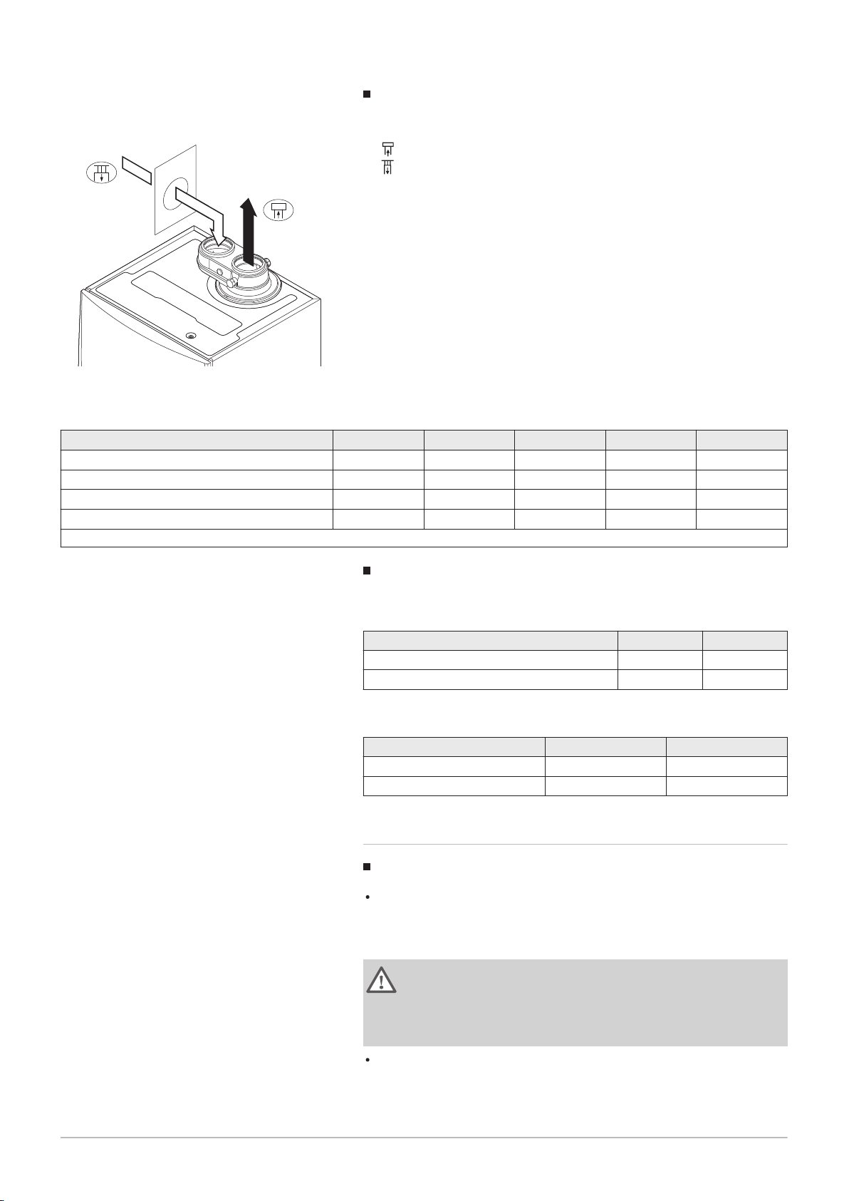
5.8.2 Access to the instrument box
Fig.26 Access to the instrument box
Fig.27
Fig.28
The following is installed in the instrument box:
the standard PCB CB-03 with connector X3.
1. Unscrew the two screws located under the front housing by a quarter
turn and remove the front housing.
2. Press the clips on the sides of the instrument box inwards slightly.
3. Tilt the instrument box forwards.
4. Press the clip on the side of the instrument box flap inwards slightly.
5. Open the instrument box flap.
The connector X3 on the CB-03 PCB is now accessible.
6. Guide the relevant connection cable(s) through the round grommet(s)
on the boiler's bottom plate.
7. Guide the relevant connection cable(s) through the instrument box via
the cable ducts provided.
8. Undo the strain relief clip(s) and feed the cable(s) underneath.
9. Connect the cables to the appropriate terminals on the connector.
10. Press the strain relief clip(s) firmly into place.
11. Close the instrument box.
5.8.3
Connection options for the standard PCB - CB-03
The boiler is fitted with a connection PCB, to which various thermostats
and regulators can be connected.
Page 40

AD-3001367-01
R-Bus
Tout
BL RL
Tdhw
X03
AD-3000968-02
Tm
R-Bus
AD-3000969-02
Tk
R-Bus
AD-3000970-02
Tk Tv
R-Bus
5 Installation
40 AMC Pro 7725131 - v.01 - 06062019
Fig.29
Connectors on the connection PCB
Fig.30 Connecting the modulating
thermostat
R-Bus
Tdhw
Room unit (thermostat) connector
BL
Blocking input
RL
Release input
Tout
Outdoor sensor connector
DHW sensor connector
When the boiler is fitted with the SCB-10 then the outdoor sensor (Tout)
and the calorifier sensor (Tdhw) must be connected on the SCB-10.
Connecting a modulating room thermostat
The boiler is fitted with a R-Bus connection as standard instead of an OTconnector. The R-Bus connector supports the following types:
R-Bus thermostat (for example, the Smart TC°)
OpenTherm thermostat (for example, the Modulating clock thermostat)
OpenTherm Smart Power thermostat
On/off thermostat
The software recognizes which type of thermostat is connected.
Tm Modulating thermostat
1. In the case of a room thermostat: install the thermostat in a reference
room.
2. Connect the two-wire cable of the modulating thermostat (Tm) to the
terminals R-Bus of the connector. It does not matter which wire is
connected to which cable clamp.
Fig.31 Connecting the on/off thermostat
Fig.32 Connection of frost thermostat
Connecting the on/off thermostat
The boiler is suitable for connection to a 2-wire on/off ambient thermostat.
Tk On/off thermostat
1. Fit the thermostat in a reference room.
2. Connect the two-wire cable of the thermostat (Tk) to the R-Bus
terminals of the connector. It does not matter which wire is connected
to which cable clamp.
Frost protection combined with on/off thermostat
When an on/off thermostat is used, the pipes and radiators in a frostsensitive room can be protected by a frost thermostat. The radiator valve
in the frost-sensitive room must be open.
Tk On/off thermostat
Tv Frost thermostat
1. Place a frost thermostat (Tv) in a frost-sensitive room (e.g. a garage).
2. Connect the frost thermostat (Tv) parallel with an on/off thermostat
(Tk) to the terminals R-Bus of the connector.
Page 41

Fig.33
AD-3000972-02
BL
AD-3001303-01
RL
7725131 - v.01 - 06062019 AMC Pro 41
Blocking input
5 Installation
Warning
If an OpenTherm thermostat (for example, the Smart TC°) is used,
a frost thermostat cannot be connected in parallel to the R-Bus
terminals. In such cases, install frost protection in the central
heating system in combination with an outdoor sensor.
Blocking input
The boiler has a blocking input. A potential-free contact can be connected
to the BL terminals of the connector. If the contact is opened, the boiler will
be blocked.
Change the function of the input using parameter AP001. This parameter
has the following 3 configuration options:
Complete blocking: no frost protection with the outdoor sensor and no
boiler frost protection (pump does not start and burner does not start)
Partial blocking: boiler frost protection (pump starts when the
temperature of the heat exchanger is < 6°C and the burner starts when
the temperature of the heat exchanger is < 3°C)
Lock out: no frost protection with outdoor sensor and partial boiler frost
protection (pump starts when the temperature of the heat exchanger is <
6°C, the burner does not start when the temperature of the heat
exchanger is < 3°C).
Caution
Only suitable for potential-free contacts.
Fig.34 Release input
Important
First remove the bridge if this input is used.
Release input
The boiler has a release input. A potential-free contact can be connected
to the RL terminals of the connector.
If the contact is closed during a heat demand, the boiler will be blocked
immediately.
If the contact is closed when there is no heat demand, the boiler will be
blocked after a waiting time.
Change the waiting time of the input using parameter AP008.
Caution
Only suitable for potential-free contacts.
Connecting an outdoor sensor
An outdoor sensor can be connected to the Tout connector. In the case of
an on/off thermostat, the boiler will control the temperature with the set
point from the internal heating curve. An OpenTherm controller can also
use this outdoor sensor. In that case, the desired internal heating curve
must be set on the controller.
Important
For boilers with an SCB-10 PCB, the outdoor sensor must be
connected to the SCB-10 PCB.
Use below mentioned sensors, or sensors with identical characteristics.
Set parameter AP056 to the installed outdoor sensor type.
AF60 = NTC 470 Ω/25°C
Page 42

AD-3000973-02
Tout
AD-3000973-02
Tout
AD-3000971-02
Tdhw
AD-4000062-01
x3
1
2
5 Installation
42 AMC Pro 7725131 - v.01 - 06062019
Fig.35
Connecting an outdoor sensor
Fig.36 Connecting an outdoor sensor
1. Connect the plug from the outdoor sensor to the Tout connector.
For more information, see
Setting the heating curve, page 0
Frost protection combined with outdoor sensor
The central heating system can also be protected against frost in
combination with an outdoor sensor. The radiator valve in the frostsensitive room must be open.
Important
For boilers with an SCB-10 PCB, the outdoor sensor must be
connected to the SCB-10 PCB.
1. Connect the plug from the outdoor sensor to the Tout connector.
The frost protection works as follows with an outdoor sensor:
If the outdoor temperature in lower than -10°C: heat demand from the
boiler and the pump starts working.
If the outdoor temperature is higher than -10°C: no heat demand from
the boiler.
Fig.37 Connecting the calorifier sensor/
thermostat
Fig.38 Access to the expansion box
Important
The outdoor temperature threshold for frost protection can be
changed with parameter AP080.
Connecting the calorifier sensor/thermostat
A calorifier sensor or thermostat can be connected to the Tdhw terminals
of the connector. Only NTC 10 kΩ/25°C sensors can be used.
Important
For boilers with an SCB-10 PCB, the calorifier sensor/thermostat
must be connected to the SCB-10 PCB.
1. Connect the two-wire cable to the Tdhw terminals of the connector.
5.8.4 Access to the expansion box
If there is no space in the boiler’s instrument box to install an (optional)
expansion PCB, install the PCB in the electronics expansion box This is
available as an accessory.
1. Unclip the housing cover.
2. Remove the cover.
3. Install the expansion PCB in accordance with the instructions
supplied.
The following is installed in the expansion box:
the SCB-10 PCB.
Page 43

Fig.39 SCB-10 PCB
AD-3001210-01
X2 X3
+TA-
TA
Tsyst Tsyst Tdhw Tflow Tflow Tflow
C AB21
R-Bus
Tout
R-Bus
R-Bus
12
3
4
+ -
Status
C AB
0-10V
N L
B
N
N L TS
N L
TS
A
N
23
2218 2019 21
5
14131211 15 16 17
43
21
109876
7725131 - v.01 - 06062019 AMC Pro 43
5 Installation
5.8.5 Connection options for the expansion PCB - SCB-10
Different heating zones can be connected to the SCB-10 PCB.
control of 2 (mixing) zones fitted on connector X15
control of a third (mixing) zone via an PCB (= accessory) fitted on
connector X8
control of one domestic hot water (DHW) zone
cascade layout (add sensor on sensor system 1 or 2)
Important
If the boiler is fitted with the SCB-10 PCB, then this is
automatically recognised by the automatic control unit of the
boiler.
On removing this control board, the boiler will show an error
code. To prevent this error, carry out an auto-detect immediately
after removing this board.
1 Outdoor temperature sensor
2 Programmable and 0-10 V input
3 Room temperature sensor - circuit C
4 Room temperature sensor - circuit B
5 Room temperature sensor - circuit A
6 Domestic hot water tank pump
7 Mixing valve - circuit B
8 Pump and safety thermostat - circuit B
9 Mixing valve - circuit A
10 Pump and safety thermostat - circuit A
11 System sensor 1
12 System sensor 2
13 Domestic hot water sensor
14 Flow sensor - circuit C
15 Flow sensor - circuit B
16 Flow sensor - circuit A
17 Impressed current anode
18 Connectors Mod-BUS
19 Coding wheel, selects the generator number in the
cascade in Mod-Bus
20 S-BUS connector
21 END connector for L-BUS connection
22 L-BUS connection to control unit (CU-GH08)
23 S-BUS cable connector
Connecting a mixing valve
Connecting a mixing valve (230 VAC) per zone (group).
Page 44

AD-4000002-01
A
N
B
N
AD-4000001-02
N L
TS
N L
TS
AD-4000123-01
N L
AD-4000006-02
Tout
AD-4000004-02
Status
1
234
+
0-10V
-
5 Installation
44 AMC Pro 7725131 - v.01 - 06062019
Fig.40 Mixing valve connectors
Fig.41 Pump with protection thermostat
connector
Connect the mixing-way valve as follows:
Earth
N
Neutral
Open
Close
Connecting the pump with a protection thermostat
Connecting a pump with a protection thermostat, e.g. for underfloor
heating. The maximum pump power consumption is 300 VA.
Connect the pump and the protection thermostat as follows:
Earth
N Neutral
L Phase
TS protection thermostat (remove bridge)
Connecting a domestic hot water (DHW) pump
Connecting a domestic hot water (DHW) pump. The maximum power
consumption is 300 VA.
Fig.42 DHW pump connector
Fig.43 Outdoor sensor
Connect the pump as follows:
Earth
N
Neutral
L
Phase
Connecting an outdoor sensor
An outdoor sensor can be connected to the Tout terminal of the connector.
In the case of an on/off thermostat, the boiler will control the temperature
with the set point from the internal heating curve.
Connecting a telephone connector
The telephone connector can be used to connect a remote control, a 0–10
V analogue input or as a status output.
The 0–10 V signal controls the boiler flow temperature in a linear way. This
control modulates on the basis of flow temperature. The output varies
between the minimum and maximum value on the basis of the flow
temperature set point calculated by the controller.
Fig.44 Telephone connector
Connect the telephone connector as follows:
0–10 V / status input
1 + 2
3 + 4 status output
Page 45

Connecting room thermostats per zone
AD-4000003-01
R-Bus R-Bus R-Bus
C B A
AD-4000009-02
Tdhw
AD-4000007-02
TflowCTflowBTflow
A
AD-4000005-02
+ TA -
TA
7725131 - v.01 - 06062019 AMC Pro 45
5 Installation
Fig.45 R-bus connectors
Fig.46 DHW sensor
Fig.47 Contact temperature sensor
connectors
The SCB-10 is fitted with three R-Bus connectors. They can be used to
connect room thermostats per zone. The R-bus connectors are related to
the other zone-specific connectors on the SCB-10.The R-Bus connector
supports the following types:
R-Bus thermostat (for example, the Smart TC°)
OpenTherm thermostat (for example, the Modulating clock thermostat)
OpenTherm Smart Power thermostat
On/off thermostat
The software recognizes which type of thermostat is connected.
Connecting the domestic hot water (DHW) sensor
Connecting the domestic hot water (DHW) sensor (NTC 10k Ohm/25°C).
Connecting contact temperature sensors
Connecting contact temperature sensors (NTC 10k Ohm/25°C) for system
flow, DHW temperatures or zones (groups).
Fig.48 Anode connector
Connecting the calorifier tank anode
Connecting a TAS anode (Titan Active System) for a calorifier tank.
Connect the anode as follows:
+
Connection on the calorifier tank
- Connection on the anode
Page 46

AD-4000093-01
X81
X81
X81
2
3
1
4
5 Installation
46 AMC Pro 7725131 - v.01 - 06062019
Caution
If the calorifier tank does not have a TAS anode, connect the
simulation anode (= accessory)
5.8.6 Connecting the standard pump
Fig.49 Connecting the power supply cable
The pump must be connected to the standard control PCB. To do this,
proceed as follows:
1. Connect the X81 power cable supplied with the boiler to the pump.
2. Remove the grommet from the opening in the middle of the base of
the boiler.
3. Pass the pump X81 cable through the base of the boiler and seal the
opening by tightening the bayonet fitting to the cable.
4. Connect the X81 pump cable to the X81 cable that runs along the
cable duct to the left of the instrument box
Page 47

5.8.7 Connecting the PWM pump
AD-4000094-01
2
3
X81
X112
4
1
5
6
X81
X81
X112
X112
7725131 - v.01 - 06062019 AMC Pro 47
5 Installation
Fig.50 Connecting the power supply cable
The energy-efficient modulating pump must be connected to the standard
control PCB. To do this, proceed as follows:
1. Connect the power supply cable and the cable for the PWM signal to
the pump.
2. Remove the grommet from the opening in the middle of the base of
the boiler.
3. Pass the pump power supply cable through the base of the boiler and
seal the opening by tightening the bayonet fitting to the cable.
4. Pass the PWM cable from the pump through one of the grommets on
the right in the base of the boiler.
5. Connect the X81 pump power supply cable to the X81 cable that runs
along the cable duct to the left of the instrument box.
6. Connect the X112 pump PWM cable to the X112 cable that runs along
the cable duct to the right of the instrument box.
Important
The pump's various settings can be adjusted using the
parameters PP014, PP016, PP017 and PP018.
Page 48

AD-0000086-01
1
3
2
AD-0000066-02
C C
1 2
6 Preparation of commissioning
48 AMC Pro 7725131 - v.01 - 06062019
6 Preparation of commissioning
6.1 Checklist before commissioning
6.1.1 Filling the siphon
Fig.51 Filling the siphon
Danger
The siphon must always be sufficiently filled with water. This
prevents flue gases from entering the room.
1. Remove the siphon.
2. Fill the siphon up with water.
3. Fit the siphon.
Check that the siphon is securely fitted and that there are no leaks.
6.1.2
Filling the system
Caution
Before filling, open the valves on every radiator in the installation.
Fig.52 Gas valve unit measuring points C
Important
In order to be able to read off the water pressure from the boiler
display, the boiler must be switched on.
1. Fill the central heating system with clean tap water.
Important
The recommended water pressure is between 1.5 bar and 2 bar.
2. Check the water-side connections for tightness.
6.1.3 Gas circuit
1 AMC Pro 45 - 65 - 90
2 AMC Pro 115
Warning
Ensure that the boiler is switched off.
Do not put the boiler into operation if the type of gas supplied
does not conform to the approved gas types.
1. Open the main gas tap.
2. Open the boiler gas tap.
3. Unscrew the two screws located under the front housing by a quarter
turn and remove the front housing.
Page 49

AD-3000932-01
3
4
1
6
2
5
6 Preparation of commissioning
7725131 - v.01 - 06062019 AMC Pro 49
4. Check the gas inlet pressure at the measuring point C on the gas
valve unit.
Warning
The gas pressure that was measured at the measuring point C
must fall within the stated gas inlet pressure limits. See
Technical data, page 77
For authorised gas pressures, see: Unit categories, page 76
5. Vent the gas supply pipe by unscrewing the measuring point on the
gas valve unit.
6. Tighten the measuring point again when the pipe has been fully
vented.
7. Check all connections for gas tightness. The maximum allowable test
pressure is 60 mbar.
6.1.4 Hydraulic circuit
1. Check the siphon; it should be fully filled with clean water.
2. Check the water-side connections for tightness.
6.2 Control panel description
Fig.53 Control panel components
6.1.5
1. Check the electrical connections.
6.2.1
Electrical connections
Control panel components
1 Rotary knob to select a tile, menu or setting
2
Confirm button to confirm the selection
3
Back button :
Short button press: Return to the previous level or previous
menu
Long button press: Return to home screen
4
Menu button to go to the main menu
5 Display
6 Status LED
For more information, see
Additional documentation, page 11
6.2.2 Description of the home screen
This screen is shown automatically after start-up of the appliance. The
control panel goes automatically in standby mode (black screen) if the
screen is not touched for 5 minutes. Press one of the buttons on the
control panel to activate the screen again.
You can navigate from any menu to the home screen by pressing the back
button for several seconds.
The tiles on the home screen provide quick access to the corresponding
menus. Use the rotary knob to navigate to the menu of your choice and
press the button to confirm the selection.
Page 50

AD-3001157-01
All OK
Error Status
22/02/2018 11:20 Home Screen
i
i
All OK
2
5
43
1
AD-3000935-01
A B
C
6 Preparation of commissioning
50 AMC Pro 7725131 - v.01 - 06062019
Fig.54 Icons on home screen
Fig.55 Items in the main menu
1 Tiles: the selected tile is highlighted
2 Date and time | Name of the screen (actual position in the menu)
3 Information about the selected tile
4 Error indicator (only visible if an error has been found)
5 Icon showing the navigation level:
: Chimney sweeper level
: User level
: Installer level
The installer level is protected by an access code. When this
level is active, the status of the tile [
] changes from Off into
On.
6.2.3 Description of the main menu
You can navigate from any menu directly to the main menu by pressing
the menu button . The number of accessible menus depends on the
access level (user or installer).
A
Date and time | Name of the screen (actual position in the menu)
B
Available menus
C
Brief explanation of the selected menu
Tab.35
Description Icon
System Settings
Version Information
Available menus for the user
Tab.36
Available menus for the installer
Description Icon
Installation Setup
Commissioning Menu
Advanced Service Menu
Error History
System Settings
Version Information
Page 51

7 Commissioning
7725131 - v.01 - 06062019 AMC Pro 51
7.1 Commissioning procedure
7 Commissioning
Warning
Initial commissioning must be done by a qualified installer.
If adapting to another type of gas, e.g. propane, the boiler must
be adjusted before it is switched it on.
See
Fan speed for different gas types, page 52
1. Open the main gas tap.
2. Open the boiler gas tap.
3. Switch the power on with the boiler's on/off switch.
The start-up program will start and cannot be interrupted. During the
program, all segments of the display are shown briefly.
4. Set the components (thermostats, control) so that heat is demanded.
Important
In the event of an error during the start-up, a message with the
corresponding code is displayed. The meaning of the error codes
can be found in the error table.
7.2 Gas settings
7.2.1 Factory setting
The factory setting of the boiler is for operation with the natural gas group
G20 (H gas).
Tab.37 Factory settings G20 (H-gas)
Code Display text Description Adjustment range 45 65 90 115
DP003 Abs. max fan
DHW
GP007 Fan RPM Max CHMaximum fan speed during
GP008 Fan RPM Min Minimum fan speed during
GP009 Fan RPM Start Fan speed at appliance start 1000 Rpm - 4000 Rpm 2500 2500 2500 2500
Maximum fan speed on Domestic
Hot Water
Central Heating mode
Central Heating + Domestic Hot
Water mode
7.2.2 Adjusting to a different gas type
Warning
Only a qualified installer may carry out the following operations.
1000 Rpm - 7000 Rpm 5400 5600 6300 6800
1400 Rpm - 7000 Rpm 5400 5600 6300 6800
1400 Rpm - 4000 Rpm 1550 1600 1600 1750
Before operating with a different type of gas, carry out the following steps.
Page 52

AD-0000067-02
A A
1 2
AD-3001378-02
00:12
0 1 2
3
4
0
1
5
6
2
0
3
4
5
1
2
3
4
1
2
3
4
0
........ .......
........ .......
........ ......... ...
..... ... ....... .... .. ..... ....... .... ..... .......
i
7 Commissioning
52 AMC Pro 7725131 - v.01 - 06062019
Adjusting the gas valve unit for propane
Important
For the AMC Pro 90 boiler; replace the current gas valve unit with
the propane gas valve unit according to the instructions supplied
with the propane conversion kit.
Fig.56 Position of adjusting screw A
Fig.57 Installer level
1 Gas valve unit on the AMC Pro 45 - 65 - 90
2 Gas valve unit on the AMC Pro 115
1. Using adjusting screw A, adjust the factory setting to the setting for
propane. The rotations for each boiler type are described in the table.
Tab.38 Settings for propane
Boiler type Action
AMC Pro 45 Rotate the adjusting screw A on the venturi 4¾
turns in a clockwise direction
AMC Pro 65 Rotate the adjusting screw A on the venturi 6½
turns in a clockwise direction
AMC Pro 115 Rotate the adjusting screw A in a clockwise direc
tion until it is closed, then:
Rotate the adjusting screw A on the gas valve unit
3½–4 turns in an anticlockwise direction
Adjusting fan speed parameters for different gas types
The factory fan speed settings can be adjusted for a different type of gas
at installer level.
1. Select the tile [ ].
2. Press the button to confirm the selection.
3. Use the rotary knob to select code: 0012.
4. Press the button to confirm the selection.
When the installer level is enabled, the status of the tile [ ]
changes from Off into On.
5. Select the tile [ ].
6. Press the button to confirm the selection.
7. Use the rotary knob to select Parameters, counters, signals.
8. Press the button to confirm the selection.
9. Use the rotary knob to select Adv. Parameters.
10. Press the button to confirm the selection.
A list of available parameters appears.
11. Use the rotary knob to select the required parameter.
12. Press the button to confirm the selection.
The current value appears.
13. Use the rotary knob to change the setting.
14. Press the button to confirm the selection.
Fan speed for different gas types
1. Adjust the fan speed (if necessary) for the gas type used according to
the table below. The setting can be changed with a parameter setting.
Tab.39 Adjustment for gas type G20 (H gas) (Switzerland)
Code Display text Description Adjustment range 45 65 90 115
DP003 Abs. max fan
DHW
GP007 Fan RPM Max CHMaximum fan speed during
GP008 Fan RPM Min Minimum fan speed during
GP009 Fan RPM Start Fan speed at appliance start 1000 Rpm - 4000 Rpm 2500 2500 2500 2500
Maximum fan speed on Domestic
Hot Water
Central Heating mode
Central Heating + Domestic Hot
Water mode
1000 Rpm - 7000 Rpm 5400 5600 6300 6800
1400 Rpm - 7000 Rpm 5400 5600 6300 6800
1400 Rpm - 4000 Rpm 1550 1600 1600 1750
Page 53

AD-0000069-01
AD-3000941-02
A
B
7 Commissioning
7725131 - v.01 - 06062019 AMC Pro 53
Tab.40 Adjustment for gas type G30/G31 (butane/propane)
Code Display text Description Adjustment range 45 65 90 115
DP003 Abs. max fan
DHW
GP007 Fan RPM Max CHMaximum fan speed during
Maximum fan speed on Domestic
Hot Water
1000 Rpm - 7000 Rpm 5100 5300 5800 6500
1400 Rpm - 7000 Rpm 5100 5300 5800 6500
Central Heating mode
GP008 Fan RPM Min Minimum fan speed during
1400 Rpm - 4000 Rpm 1550 1600 2250 1800
Central Heating + Domestic Hot
Water mode
GP009 Fan RPM Start Fan speed at appliance start 1000 Rpm - 4000 Rpm 2500 2500 2500 2500
Tab.41 Adjustment for gas type G31 (propane)
Code Display text Description Adjustment range 45 65 90 115
DP003 Abs. max fan
DHW
GP007 Fan RPM Max CHMaximum fan speed during
Maximum fan speed on Domestic
Hot Water
1000 Rpm - 7000 Rpm 5100 5400 6000 6700
1400 Rpm - 7000 Rpm 5100 5400 6000 6700
Central Heating mode
GP008 Fan RPM Min Minimum fan speed during
1400 Rpm - 4000 Rpm 1550 1600 2000 1800
Central Heating + Domestic Hot
Water mode
GP009 Fan RPM Start Fan speed at appliance start 1000 Rpm - 4000 Rpm 3000 2500 2500 3500
Fig.58 Flue gas measuring point
Fig.59 Full load test
2. Check the setting of the gas/air ratio.
7.2.3 Checking and setting the gas/air ratio
1. Unscrew the cap from the flue gas measuring point.
2. Insert the probe for the flue gas analyser into the measurement
opening.
Warning
During measurement, seal the opening around the sensor fully.
Caution
The flue gas analyser must have a minimum accuracy of ±0.25%
O2.
3. Measure the percentage of O2 in the flue gases. Take measurements
at full load and at part load.
Important
Measurements must be taken with the front casing off.
Performing the full load test
1. Select the tile [ ].
The Change load test mode menu appears.
2. Select the test MaximumPowerCH.
Change load test mode
A
B MaximumPowerCH
The full load test starts. The selected load test mode is shown in the
menu and the icon appears in the top right of the screen.
3. Check the load test settings and adjust if necessary.
Only the parameters shown in bold can be changed.
Page 54

AD-0000067-02
A A
1 2
7 Commissioning
54 AMC Pro 7725131 - v.01 - 06062019
Checking/setting values for O2 at full load
Fig.60 Position of adjusting screw A
1 AMC Pro 45 - 65 - 90
2 AMC Pro 115
1. Measure the percentage of O2 in the flue gases.
2. Compare the measured value with the checking values in the table.
3. If the measured value is outside of the values given in the table,
correct the gas/air ratio.
Warning
Only a qualified installer may carry out the following operations.
4. Using adjusting screw A, adjust the percentage of O2 for the gas type
being used to the nominal value. This should always be inside the
highest and lowest setting limit.
Tab.42 Checking/setting values for O2 at full load for G20 (H gas)
Values at full load for G20 (H gas)
AMC Pro 45 4,3 - 4,8
AMC Pro 65 4,3 - 4,8
AMC Pro 90 4,3 - 4,7
AMC Pro 115 4,2 - 4,7
(1) Nominal value
O2 (%)
(1)
(1)
(1)
(1)
(1)
Tab.43 Checking/setting values for O2 at full load for G20 (H gas)
(Switzerland)
Values at full load for G20 (H gas)
AMC Pro 45 4,3 - 4,8
AMC Pro 65 4,3 - 4,8
AMC Pro 90 4,3 - 4,7
AMC Pro 115 4,2 - 4,7
(1) Nominal value
O2 (%)
(1)
(1)
(1)
(1)
(1)
Tab.44 Checking/setting values for O2 at full load for G31 (propane)
Values at full load for G31 (propane)
AMC Pro 45 4,4 - 4,9
AMC Pro 65 4,6 - 4,9
AMC Pro 90 5,1 - 5,2
AMC Pro 115 4,9 - 5,4
(1) Nominal value
O2 (%)
(1)
(1)
(1)
(1)
(1)
Tab.45 Checking/setting values for O2 at full load for G30/G31
(butane/propane)
Values at full load for G30/G31 (butane/propane)
AMC Pro 45 4,7 - 5,2
AMC Pro 65 4,9 - 5,4
AMC Pro 90 4,9 - 5,4
AMC Pro 115 4,9 - 5,4
(1) Nominal value
O2 (%)
(1)
(1)
(1)
(1)
(1)
Caution
The O2 values at full load must be lower than the O2 values at part
load.
Page 55

Fig.61 Part load test
AD-3000941-02
A
B
AD-0000072-02
B B
B
1 2
7725131 - v.01 - 06062019 AMC Pro 55
7 Commissioning
Performing the part load test
1. If the full load test is still running, press the button to change the
load test mode.
2. If the full load test was finished, select the tile [ ] to restart the
chimney sweep menu.
A Change load test mode
B MinimumPower
3. Select the MinimumPower test in the menu Change load test mode.
The part load test starts. The selected load test mode is shown in
the menu and the icon appears in the top right of the screen.
4. Check the load test settings and adjust if necessary.
Only the parameters shown in bold can be changed.
5. End the part load test by pressing the button.
The message Running load test(s) stopped! is displayed.
Checking/setting values for O2 at part load
Fig.62 Position of adjusting screw B
1 AMC Pro 45 - 65 - 90
2 AMC Pro 115
1. Measure the percentage of O2 in the flue gases.
2. Compare the measured value with the checking values in the table.
3. If the measured value is outside of the values given in the table,
correct the gas/air ratio.
Warning
Only a qualified installer may carry out the following operations.
4. Using adjusting screw B, adjust the percentage of O2 for the gas type
being used to the nominal value. This should always be inside the
highest and lowest setting limit.
5. Set the boiler back to the normal operating status.
Tab.46 Checking/setting values for O2 at part load for G20 (H gas)
Values at part load for G20 (H gas)
AMC Pro 45 5,7
AMC Pro 65 4,8
AMC Pro 90 5,2
AMC Pro 115 5,6
(1) Nominal value
O2 (%)
(1)
- 6,2
(1)
- 5,3
(1)
- 4,8
(1)
- 6,1
(1)
Tab.47 Checking/setting values for O2 at part load for G20 (H gas)
(Switzerland)
Values at part load for G20 (H gas)
O2 (%)
AMC Pro 45 5,7
AMC Pro 65 4,8
AMC Pro 90 5,2
AMC Pro 115 5,6
(1) Nominal value
Tab.48 Checking/setting values for O2 at part load for G31
(propane)
Values at part load for G31 (propane)
O2 (%)
AMC Pro 45 5,7
AMC Pro 65 5,4
(1)
(1)
(1)
(1)
(1)
(1)
(1)
- 6,2
- 5,3
- 4,8
- 6,1
(1)
- 6,2
- 5,7
Page 56

AD-3001124-01
Adjusted for / Réglée pour /
Ingesteld op / Eingestellt auf
/ Regolato per / Ajustado
para / Ρυθμισμένο για /
Nastawiony na / настроен
для / Reglat pentru /
настроен за / ayarlanmıştır /
Nastavljen za / beállítva/
Nastaveno pro / Asetettu
kaasulle / Justert for/
indstillet til/ ضبط ل :
C
(10)3(X)
Gas
C
(12)3(X)
mbar
Parameters / Paramètres /
Parameter / Parametri /
Parámetros / Παράμετροι /
Parametry / Параметры /
Parametrii / Параметри /
Parametreler / Paraméterek
/ Parametrit / Parametere /
Parametre / المعلمات :
G20
20
DP003 - 3300
GP007 - 3300
GP008 - 2150
GP009 -
7 Commissioning
56 AMC Pro 7725131 - v.01 - 06062019
7.3 Final instructions
Fig.63
Example filled-in sticker
Values at part load for G31 (propane)
AMC Pro 90 5,5
AMC Pro 115 5,8
(1) Nominal value
O2 (%)
(1)
- 5,8
(1)
- 6,3
(1)
Tab.49 Checking/setting values for O2 at part load for G30/G31
(butane/propane)
Values at part load for G30/G31 (butane/propane)
AMC Pro 45 5,7
AMC Pro 65 5,7
AMC Pro 90 5,7
AMC Pro 115 5,7
(1) Nominal value
O2 (%)
(1)
- 6,2
(1)
- 6,2
(1)
- 6,2
(1)
- 6,2
(1)
Caution
The O2 values at part load must be higher than the O2 values at
full load.
1. Remove the measuring equipment.
2. Screw the cap on to the flue gas measuring point.
3. Seal the gas valve unit.
4. Put the front casing back.
5. Heat the central heating system up to approximately 70°C.
6. Switch the boiler off.
7. Vent the central heating system after approx. 10 minutes.
8. Turn on the boiler.
9. Check the water pressure. If necessary, top up the central heating
system.
10. Fill in the following data on the sticker included, and attach it next to
the data plate on the appliance.
The gas supply pressure;
If set to overpressure application, fill in the type;
The parameters modified for the changes mentioned above.
11. Optimise the settings as required for the system and user
preferences.
See
For more information; Settings, page 57 and User instructions,
page 68.
12. Instruct the user in the operation of the system, boiler and controller.
13. Inform the user of the maintenance to be performed.
14. Hand over all manuals to the user.
Page 57

8 Settings
AD-3001373-02
00:12
...... ......
........ .......
........ .......
....................
..... ... ....... .... .. ..... ....... .... ..... .......
..... ... ....... .... .. ..... ....
.........
..... ... ....... ....
..... ... ....... ....
....... .... .. ..... .... .......
....... ...........
......
.....
...
CP010
CP010
AD-3001375-01
CP010
AD-3001376-01
CP010
AD-3001377-01
CP010
7725131 - v.01 - 06062019 AMC Pro 57
8.1 Introduction to parameter codes
8 Settings
Fig.64 Code on a Diematic Evolution
Fig.65 First letter
Fig.66 Second letter
The controls platform makes use of an advanced system to categorise
parameters, measurements and counters. Knowing the logic behind these
codes, makes it easier to identify them. The code consists of two letters
and three numbers.
The first letter is the category the code relates to.
A Appliance: Appliance
C Circuit: Zone
D Domestic hot water: Domestic hot water
G Gas fired: Gas-fired heat engine
P Producer: Central heating
Category D codes are appliance controlled only. When the domestic hot
water is controlled by an SCB, it is handled like a circuit, with C-category
codes.
The second letter is the type.
P Parameter: Parameters
C Counter: Counters
M Measurement: Signals
Fig.67 Number
8.2 Changing the parameters
The number is always three digits. In certain cases, the last of the three
digits relates to a zone.
The boiler’s control unit is set for the most common central heating
systems. These settings will ensure that virtually every central heating
system operates effectively. The user or the installer can optimise the
parameters as required.
Caution
Changing the factory settings may adversely affect the operation
of the boiler.
For more information, see
Additional documentation, page 11
8.2.1 Accessing the installer level
Some parameters that may affect the operation of the boiler are protected
by an access code. Only the installer is allowed to modify these
parameters.
1. Select the tile [ ].
2. Press the button to confirm the selection.
Page 58

AD-3001378-02
00:12
0 1 2
3
4
0
1
5
6
2
0
3
4
5
1
2
3
4
1
2
3
4
0
........ .......
........ .......
........ ......... ...
..... ... ....... .... .. ..... ....... .... ..... .......
i
8 Settings
58 AMC Pro 7725131 - v.01 - 06062019
Fig.68
Installer level
3. Use the rotary knob to select code: 0012.
4. Press the button to confirm the selection.
5. To leave the installer level, select the tile [ ] .
6. Use the rotary knob to select Confirm or Cancel.
7. Press the button to confirm the selection.
When the control panel is not used for 30 minutes, the installer level is left
automatically.
Configuring the installation at installer level
Configure the installation by pressing the button and selecting
Installation Setup . Select the control unit or circuit board you want to
configure:
Tab.50 CU-GH08
Icon Zone or function Description
CIRCA / CH Central heating circuit
Gas fired appliance Gas boiler
Tab.51 SCB-10
Icon Zone or function Description
CIRCA Central heating circuit A
CIRCB Central heating circuit B
DHW Domestic hot water external circuit
CIRCC Central heating circuit C
0-10 volt input 0–10 volt input signal
Digital Input Digital input signal
Analogue input Analogue input signal
Cascade management B Management of a cascade of multiple boilers
Buffer Tank Schedule Enable a buffer tank with one or two sensors
Outdoor temperature Outdoor sensor
Status information PCB SCB-10 status information
When the installer level is enabled, the status of the tile [ ]
changes from Off into On.
When the installer level is disabled, the status of the tile [ ]
changes from On into Off.
Tab.52 Configuring a zone or function of CU-GH08 or SCB-10
Parameters, counters, signals Description
Parameters Set the parameters at installer level
Counters Read the counters at installer level
Signals Read the signals at installer level
Adv. Parameters Set the parameters at advanced installer level
Adv. Counters Read the counters at advanced installer level
Adv. Signals Read the signals at advanced installer level
8.2.2
Changing boiler parameters when SCB-10 is fitted
When the boiler is fitted with the SCB-10 the following boiler CU-GH08
parameter(s) at installer level must be checked and adjusted, if necessary:
Page 59

AD-4100424-01
F
M
1500 2500 3500 4500 5500 6500 7500
0
20
R
Q
40
41,2
60
5400
AD-4100427-01
60
1500 2500 3500 4500 5500 6500 7500
0
20
R
Q
40
62
80
5600
F
M
8 Settings
7725131 - v.01 - 06062019 AMC Pro 59
Tab.53 Installation Setup > CU-GH08 > CIRCA > Parameters, counters, signals > Parameters
Code Display text Description Range Adjust
ment
CP020 Zone Function Functionality of the zone 0 = Disable
0
1 = Direct
2 = Mixing Circuit
3 = Swimming pool
4 = High Temperature
5 = Fan Convector
6 = DHW tank
7 = Electrical DHW
8 = Time Program
9 = ProcessHeat
10 = DHW Layered
11 = DHW Internal tank
31 = DHW FWS EXT
Tab.54 Installation Setup > CU-GH08 > Gas fired appliance > Parameters, counters, signals > Parameters
Code Display text Description Range Adjust
ment
AP102 Boiler Pump function Configuration of the boiler pump as
zone pump or system pump (feed
0 = No
1 = Yes
0
lowloss header)
Tab.55 Installation Setup > CU-GH08 > Tank DHW > Parameters, counters, signals > Parameters
Code Display text Description Range Adjust
ment
DP007 Dhw 3wv Standby Position of three way valve during
standby
8.2.3
Setting the maximum load for CH operation
0 = CH position
1 = DHW position
0
See the graphs for the relationship between load and speed for natural
gas. The speed can be changed using parameter GP007.
Fig.69 Load AMC Pro 45
Fig.70 Load AMC Pro 65
M
Maximum heat input
F
Factory setting
Q
Input (Hi) (kW)
R
Fan speed (rpm)
M
Maximum heat input
F
Factory setting
Q
Input (Hi) (kW)
R
Fan speed (rpm)
Page 60

AD-4100429-01
1500 2500 3500 4500 5500 6500 7500
0
20
R
Q
40
60
80
86
100
6300
F
M
AD-4100431-01
1500 2500 3500 4500 5500 6500 7500
0
20
R
Q
40
60
80
100
107
120
6800
F
M
AD-3001402-01
.... ...... ........ ..............
11:20
.... ...
... ....
...... ...
... ...
........ ...................
........ ...................
.... .....
D
B
A
C
8 Settings
60 AMC Pro 7725131 - v.01 - 06062019
Fig.71
Load AMC Pro 90
Fig.72 Load AMC Pro 115
M
Maximum heat input
F
Factory setting
Q
Input (Hi) (kW)
R
Fan speed (rpm)
M
Maximum heat input
F
Factory setting
Q
Input (Hi) (kW)
R
Fan speed (rpm)
8.2.4 Setting the heating curve
When an outdoor temperature sensor is connected to the installation, the
relation between the outdoor temperature and the central heating flow
temperature is controlled by a heating curve. This curve can be adjusted
to the requirements of the installation.
1. Select the tile of the zone you want to configure.
2. Select Control strategy.
3. Select the setting Outdoor Temp. based or Outdoor & room based.
The option Heating Curve appears in the Zone setup menu.
4. Select Heating Curve.
A graphic display of the heating curve is shown.
Fig.73 The heating curve
5. Adjust the following parameters:
Tab.56 Settings
A Slope: Slope of the heating curve:
Floor heating circuit: slope between 0.4 and 0.7
Radiator circuit: slope at approximately 1.5
B Max: Maximum temperature of the heating circuit
C Base: Ambient temperature setpoint
D xx°C ; xx°CRelationship between the heating circuit flow
temperature and the outdoor temperature. This
information is visible throughout the slope.
8.2.5 Setting for process heat application
Important
The service life of the boiler may be reduced if it is used for
process heat applications.
For this application, adjust the following parameters:
1. Set parameter DP140 to Process heat.
Page 61

8 Settings
7725131 - v.01 - 06062019 AMC Pro 61
2. Set parameters DP005 and DP070 to the required value for this
installation.
3. If using a DHW sensor; set parameters DP006 and DP034 to the
required value for this installation.
8.2.6 Changing the default ΔT setting
The ΔT can be increased with a parameter setting. When increasing the
ΔT, the control unit limits the flow temperature to a maximum of 80 °C.
1. Set parameter GP021 to the required temperature.
Tab.57 Increasing default ΔT setting
Boiler type Default ΔT setting Maximum ΔT setting
AMC Pro 45
AMC Pro 65
AMC Pro 90
AMC Pro 115 20 °C 35 °C
2. If a PWM-controlled central heating-pump is controlled by the boiler
control unit; set parameter PP014 to 2 °C.
25 °C 40 °C
8.3
List of parameters
8.3.1 Control unit settings
Important
All tables show the factory setting for the parameters.
All possible options are indicated in the adjustment range. The
display of the boiler only shows the relevant settings for the
appliance.
Tab.58 Navigation for basic installer level
Level Menu cascade
Basic installer
(1) See the column "Submenu" in the following table for the correct navigation. The parameters are grouped in specific functionalities.
> Installation Setup > CU-GH08 > Submenu
Tab.59 Factory settings at basic installer level
Code Display text Description Range Submenu 45 65 90 115
AP016 CH function onEnable central heating heat
demand processing
AP017 DHW function onEnable domestic hot water
heat demand processing
AP073 Summer
Winter
AP074 Force
summer mode
Outdoor temperature: upper
limit for heating
The heating is stopped. Hot
water is maintained. Force
0 = Off
1 = On
0 = Off
1 = On
10 °C - 30 °C Outdoor
0 = Off
1 = On
Summer Mode
AP083 Enable
master func
Enable the master
functionality of this device on
0 = No
1 = Yes
the S-Bus for system control
AP089 Installer name Name of the installer Mandator
AP090 Installer
phone
Telephone number of the
installer
Mandator
(1)
> Parameters, counters, signals > Parameters
Gas fired
1 1 1 1
appliance
Gas fired
1 1 1 1
appliance
22 22 22 22
temperatu
re
Outdoor
0 0 0 0
temperatu
re
Mandator
0 0 0 0
y bus
master
None None None None
y bus
master
0 0 0 0
y bus
master
Page 62

8 Settings
62 AMC Pro 7725131 - v.01 - 06062019
Code Display text Description Range Submenu 45 65 90 115
AP107 Color display
Mk2
Color display Mk2 0 = White
1 = Red
2 = Blue
Mandator
y bus
master
2 2 2 2
3 = Green
4 = Orange
5 = Yellow
6 = Violet
CP010 Tflow setpoint
zone
Zone flow temperature
setpoint, used when the zone
0 °C - 90 °C Direct
zone
80 80 80 80
is set to a fixed flow setpoint.
CP080 User T.Room
Activity
CP081 User T.Room
Activity
CP082 User T.Room
Activity
CP083 User T.Room
Activity
CP084 User T.Room
Activity
CP085 User T.Room
Activity
CP200 Manu
ZoneRoomTe
mpSet
CP320 OperatingZon
eMode
Room setpoint temperature of
5 °C - 30 °C Direct
the user zone activity
Room setpoint temperature of
5 °C - 30 °C Direct
the user zone activity
Room setpoint temperature of
5 °C - 30 °C Direct
the user zone activity
Room setpoint temperature of
5 °C - 30 °C Direct
the user zone activity
Room setpoint temperature of
5 °C - 30 °C Direct
the user zone activity
Room setpoint temperature of
5 °C - 30 °C Direct
the user zone activity
Manually setting the room
5 °C - 30 °C Direct
temperature setpoint of the
zone
Operating mode of the zone 0 = Scheduling
1 = Manual
zone
zone
zone
zone
zone
zone
zone
Direct
zone
16 16 16 16
20 20 20 20
6 6 6 6
21 21 21 21
22 22 22 22
20 20 20 20
20 20 20 20
1 1 1 1
2 = Antifrost
3 = Temporary
CP510 Temporary
Room Setp
CP550 Zone, fire
place
CP660 Icon display
zone
Temporary room setpoint per
5 °C - 30 °C Direct
zone
Fire Place mode is active 0 = Off
1 = On
Choice icon to display this
zone
0 = None
1 = All
zone
Direct
zone
Direct
zone
20 20 20 20
0 0 0 0
3 3 3 3
2 = Bedroom
3 = Livingroom
4 = Study
5 = Outdoor
6 = Kitchen
7 = Basement
8 = Swimming Pool
9 = DHW Tank
10 = DHW Electrical
Tank
11 = DHW Layered
Tank
12 = Internal Boiler
Tank
13 = Time Program
DP060 DHW
timeprog.
select
Time program selected for
DHW.
0 = Schedule 1
1 = Schedule 2
2 = Schedule 3
Internal
DHW
0 0 0 0
3 = Cooling
DP070 DHW comfort
setpoint
Comfort temperature setpoint
from the Domestic Hot Water
40 °C - 65 °C Internal
DHW
60 60 60 60
tank
DP080 DHW reduced
setpoint
Reduced temperature setpoint
from the Domestic Hot Water
7 °C - 50 °C Internal
DHW
15 15 15 15
tank
Page 63

8 Settings
7725131 - v.01 - 06062019 AMC Pro 63
Code Display text Description Range Submenu 45 65 90 115
DP200 DHW mode DHW primary mode current
working setting
0 = Scheduling
1 = Manual
Internal
DHW
1 1 1 1
2 = Antifrost
3 = Temporary
DP337 DHW holiday
setpoint
Holiday temperature setpoint
from the Domestic Hot Water
10 °C - 60 °C Internal
DHW
10 10 10 10
tank
Tab.60 Navigation for installer level
Level Menu cascade
Installer
(1) See the column "Submenu" in the following table for the correct navigation. The parameters are grouped in specific functionalities.
> Installation Setup > CU-GH08 > Submenu
(1)
> Parameters, counters, signals > Parameters
Tab.61 Factory settings at installer level
Code Display text Description Range Submenu 45 65 90 115
AP001 BL input
setting
Blocking input setting (1: Full
blocking, 2: Partial blocking,
3: User reset locking)
1 = Full blocking
2 = Partial blocking
3 = User reset locking
Gas fired
appliance
1 1 1 1
4 = Backup relieved
5 = Generator
relieved
6 = Gen.&Backup
relieved
7 = High, Low Tariff
8 = Photovoltaic HP
Only
9 = PV HP And
backup
10 = Smart Grid ready
11 = Heating Cooling
AP003 Flue Valve
Wait Time
Wait time after burner
command to open flue gas
0 Sec - 255 Sec Gas fired
appliance
0 0 0 0
valve
AP006 Min. water
pressure
AP008 Time release
signal
Appliance will report low water
pressure below this value
The appliance will wait x sec
(0=off) for the release contact
0 bar - 6 bar Gas fired
appliance
0 Sec - 255 Sec Gas fired
appliance
0,8 0,8 0,8 0,8
0 0 0 0
to close in order to start the
burner
AP009 Service hours
burner
AP010 Service
notification
Burning hours before raising a
service notification
The type of service needed
based on burn and powered
hours
0 Hours - 51000
Hours
0 = None
1 = Custom
notification
Gas fired
appliance
Gas fired
appliance
6000 6000 6000 6000
0 0 0 0
2 = ABC notification
AP011 Service hours
mains
AP063 CH Set Max
System
Hours powered to raise a
service notification
Maximum flow temperature
setpoint for burning at central
0 Hours - 51000
Hours
Gas fired
appliance
20 °C - 90 °C Gas fired
appliance
35000 35000 35000 35000
90 90 90 90
heating
AP079 Building
Inertia
Inertia of the building used for
heat up speed
0 - 15 Outdoor
temperatu
3 3 3 3
re
AP080 Frost min out
temp
AP082 Enable
daylight save
Outside temperature below
which the antifreeze
protection is activated
Enable daylight saving for the
system to save energy during
winter
-60 °C - 25 °C Outdoor
temperatu
re
0 = Off
1 = On
Mandator
y bus
master
-10 -10 -10 -10
1 1 1 1
Page 64

8 Settings
64 AMC Pro 7725131 - v.01 - 06062019
Code Display text Description Range Submenu 45 65 90 115
AP091 Outside Sens.
Source
Type of outside sensor
connection to be used
0 = Auto
1 = Wired sensor
2 = Wireless sensor
Outdoor
temperatu
re
0 0 0 0
3 = Internet measured
4 = None
AP108 OutsideSenso
rEnabled
Enable the function Outside
Sensor
0 = Auto
1 = Wired sensor
2 = Wireless sensor
Outdoor
temperatu
re
0 0 0 0
3 = Internet measured
4 = None
CP000 MaxZoneTFlo
wSetpoint
CP020 Zone Function Functionality of the zone 0 = Disable
Maximum Flow Temperature
setpoint zone
0 °C - 90 °C Direct
zone
Direct
1 = Direct
zone
80 80 80 80
1 1 1 1
2 = Mixing Circuit
3 = Swimming pool
4 = High Temperature
5 = Fan Convector
6 = DHW tank
7 = Electrical DHW
8 = Time Program
9 = ProcessHeat
10 = DHW Layered
11 = DHW Internal
tank
12 = DHW
Commercial Tank
31 = DHW FWS EXT
CP060 RoomT.
Holiday
CP070 MaxReduced
RoomT.Lim
Wished room zone
temperature on holiday period
Max Room Temperature limit
of the circuit in reduced mode,
5 °C - 20 °C Direct
zone
5 °C - 30 °C Direct
zone
6 6 6 6
16 16 16 16
that allows switching to
comfort mode
CP210 Zone HCZP
Comfort
Comfort footpoint of the
temperature of heat curve of
15 °C - 90 °C Direct
zone
15 15 15 15
the circuit
CP220 Zone HCZP
Reduced
Reduced footpoint of the
temperature of heat curve of
15 °C - 90 °C Direct
zone
15 15 15 15
the circuit
CP230 Zone Heating
Curve
CP340 TypeReduced
NightMode
CP470 Zone screed
drying
CP480 ScreedStartT
emp
Heating curve temperature
gradient of the zone
Type of reduced night mode,
stop or maintain heating of
circuit
Setting of the screed drying
program of the zone
Setting of the start
temperature of the screed
0 - 4 Direct
zone
0 = Stop heat demand
1 = Continue heat
Direct
zone
demand
0 Days - 30 Days Direct
zone
20 °C - 50 °C Direct
zone
1,5 1,5 1,5 1,5
1 1 1 1
0 0 0 0
20 20 20 20
drying program of the zone
CP490 ScreedStopTempSetting of the stop
temperature of the screed
20 °C - 50 °C Direct
zone
20 20 20 20
drying program of the zone
CP570 ZoneTimePro
g Select
Time Program of the zone
selected by the user
0 = Schedule 1
1 = Schedule 2
Direct
zone
0 0 0 0
2 = Schedule 3
3 = Cooling
Page 65

8 Settings
7725131 - v.01 - 06062019 AMC Pro 65
Code Display text Description Range Submenu 45 65 90 115
CP730 Zone Heat up
speed
Selection of heat up speed of
the zone
0 = Extra Slow
1 = Slowest
Direct
zone
3 3 3 3
2 = Slower
3 = Normal
4 = Faster
5 = Fastest
CP740 Zone cool
down speed
Selection of cool down speed
of the zone
0 = Slowest
1 = Slower
Direct
zone
2 2 2 2
2 = Normal
3 = Faster
4 = Fastest
CP750 MaxZone
Preheat time
CP780 Control
strategy
Maximum zone preheat time 0 Min - 240 Min Direct
zone
Selection of the control
strategy for the zone
0 = Automatic
1 = Room Temp.
Direct
zone
90 90 90 90
0 0 0 0
based
2 = Outdoor Temp.
based
3 = Outdoor & room
based
DP004 Legionella
calor.
Legionella mode protection
calorifier
0 = Disabled
1 = Weekly
Tank
DHW
1 1 1 1
2 = Daily
DP007 Dhw 3wv
Standby
DP035 Start pump
DHW calo
DP150 DHW
Thermostat
DP160 DHW AntiLeg
Setpoint
DP170 Start time
holiday
DP180 End time
holiday
GP017 Max power Maximum power percentage
GP050 Power Min Minimum power in kilo Watt
PP015 CH Pump
postrun time
Position of three way valve
during standby
Start pump for Domestic Hot
Water calorifier
Set DHW Thermostat function
On or Off
Setpoint for DHW anti
legionella
Start time of holiday Time
stamp
End time of holiday
Timestamp
in kilo Watt
for RT2012 calculation
Central heating pump post run
time
0 = CH position
1 = DHW position
Tank
DHW
-20 °C - 20 °C Tank
DHW
0 = Off
1 = On
Tank
DHW
50 °C - 90 °C Internal
DHW
Internal
DHW
Internal
DHW
0 kW - 80 kW Gas fired
appliance
0 kW - 80 kW Gas fired
appliance
0 Min - 99 Min Gas fired
appliance
0 0 0 0
-3 -3 -3 -3
1 1 1 1
70 70 70 70
- - - -
- - - -
71,5 103,6 124,5 140,9
4,7 6,7 10,8 11,4
1 1 1 1
Tab.62 Navigation for advanced installer level
Level Menu cascade
Advanced installer
> Installation Setup > CU-GH08 > Submenu
(1)
> Parameters, counters, signals > Parameters > Adv.
Parameters
(1) See the column "Submenu" in the following table for the correct navigation. The parameters are grouped in specific functionalities.
Tab.63 Factory settings at advanced installer level
Code Display text Description Range Submenu 45 65 90 115
AP002 Manual Heat
Demand
Enable manual heat demand
function
0 = Off
1 = With setpoint
Gas fired
appliance
0 0 0 0
2 = TOutdoor Control
AP026 Setpoint
manual HD
AP056 Outdoor
sensor
Flow temperature setpoint for
10 °C - 90 °C Gas fired
manual heat demand
Enable outdoor sensor 0 = No outside sensor
1 = AF60
2 = QAC34
appliance
Outdoor
temperatu
re
40 40 40 40
1 1 1 1
Page 66

8 Settings
66 AMC Pro 7725131 - v.01 - 06062019
Code Display text Description Range Submenu 45 65 90 115
AP102 Boiler Pump
function
Configuration of the boiler
pump as zone pump or
0 = No
1 = Yes
Gas fired
appliance
0 0 0 0
system pump (feed lowloss
header)
AP111 Can line
length
CP130 T.OutdoorToZ
one
CP240 ZoneRoomUn
itInfl
CP250 CalSondeAm
bZone
CP770 Zone Buffered The zone is after a Buffer tank 0 = No
DP003 Abs. max fan
DHW
DP005 Calorifier Tf
offset
DP006 Hyst calorifier Hysteresis to start heating
DP020 Postrun DHW
pump/3wv
Can line length 0 = < 3m
1 = < 80m
2 = < 500m
Assigning the outdoor sensor
0 - 4 Direct
to zone …
Adjustment of the influence of
0 - 10 Direct
the zone room unit
Mandator
y bus
master
zone
zone
Calibration of Zone Room Unit -5 °C - 5 °C Direct
zone
Direct
Maximum fan speed on
Domestic Hot Water
Flow setpoint offset for
loading calorifier
1 = Yes
1000 Rpm - 7000
Rpm
0 °C - 50 °C Tank
zone
Gas fired
appliance
DHW
2 °C - 15 °C Tank
calorifier
Post run time of the DHW
pump/3 way valve after DHW
0 Sec - 99 Sec Gas fired
DHW
appliance
0 0 0 0
0 0 0 0
3 3 3 3
0 0 0 0
0 0 0 0
5400 5600 6300 6700
20 20 20 20
5 5 5 5
10 10 10 10
production
DP034 DhwCalorifier
Offset
DP140 DHW load
type
Offset for calorifier sensor 0 °C - 10 °C Tank
DHW
DHW load type (0 : Combi, 1 :
Solo)
0 = Combi
1 = Solo
2 = Layered cylinder
3 = Process heat
4 = External
Internal
DHW
Tank
DHW
Gas fired
2 2 2 2
1 1 1 1
appliance
GP007 Fan RPM Max CHMaximum fan speed during
Central Heating mode
GP008 Fan RPM Min Minimum fan speed during
Central Heating + Domestic
1400 Rpm - 7000
Rpm
1400 Rpm - 4000
Rpm
Gas fired
appliance
Gas fired
appliance
5400 5600 6300 6800
1550 1600 1600 1750
Hot Water mode
GP009 Fan RPM
Start
GP010 GPS Check Gas Pressure Switch check
GP021 Temp diff
Modulating
Fan speed at appliance start 1000 Rpm - 4000
Rpm
0 = No
on/off
Modulate back when delta
1 = Yes
10 °C - 40 °C Gas fired
temperature is large then this
Gas fired
appliance
Gas fired
appliance
appliance
2500 2500 2500 2500
0 0 0 0
25 25 25 20
treshold
GP022 Tfa Filter Tau Tau factor for average flow
temperature calculation
PP014 ChPumpDTR
eduction
Reduction of temperature
delta modulating for pump
1 - 255 Gas fired
appliance
0 °C - 40 °C Gas fired
appliance
1 1 1 1
18 18 18 18
modulation
PP016 Max. CH
pump speed
PP017 ChPumpSpee
dMaxFactor
Maximum central heating
pump speed (%)
Maximum central heating at
minimum load as percentage
20 % - 100 % Gas fired
appliance
0 % - 100 % Gas fired
appliance
100 100 100 100
100 100 100 100
of max pump speed
PP018 Min CH pump
speed
PP023 Start
hysteresis CH
Minimum central heating
pump speed (%)
Hysteresis to start burner in
heating mode
20 % - 100 % Gas fired
appliance
1 °C - 10 °C Gas fired
appliance
30 30 30 30
10 10 10 10
Page 67

8.3.2 SCB-10 expansion PCB settings
7725131 - v.01 - 06062019 AMC Pro 67
See
The boiler service manual for the SCB-10 expansion PCB
settings. This manual can be found on the website.
8 Settings
Page 68

AD-3001387-01
Not set
Home Screen
22/02/2018 11:20
... ...
........ .......
........ .......
......
AD-3001388-01
... ...
........ .......
........ .......
......
Not set
Home Screen
22/02/2018 11:20
9 User instructions
68 AMC Pro 7725131 - v.01 - 06062019
9 User instructions
9.1 Accessing the user level menus
Fig.74 Menu selection
The tiles on the home screen provide quick access for the user to the
corresponding menus.
1. Use the rotary knob to select the required menu.
Fig.75 Confirm menu selection
2. Press the button to confirm the selection.
3. Use the rotary knob to select the desired setting.
4. Press the button to confirm the selection.
5. Use the rotary knob to change the setting.
6. Press the button to confirm the selection.
7. Use the rotary knob to select the next setting or press the button to
9.2 Home screen
The tiles on the home screen provide quick access to the corresponding
menus. Use the rotary knob to navigate to the menu of your choice and
press the button to confirm the selection. All options for change will
appear in the display (Cannot edit read-only datapoint will appear in the
display if a setting cannot be changed).
Tab.64 Selectable tiles for the user
Tile Menu Function
Information menu. Read out various current values.
Error indicator. Read out details about the current error.
With some errors the icon will appear with installer contact details (when
filled in).
Holiday mode. Set the start and end date of your holiday to lower the room and domestic hot
water temperatures of all zones.
Gas boiler indicator. Read out burning details of the boiler and switch the heating function of the
boiler on or off.
Water pressure indicator. Shows the water pressure. Top up the installation when the water pressure is
too low.
Heating circuit set-up. Configure the settings per heating circuit.
, ,
, ,
, ,
The available settings of this selected menu appear in the display.
All options for change will appear in the display (if a setting cannot
be changed, Cannot edit read-only datapoint will appear in the
display).
return to the home screen.
DHW setup. Configure the domestic hot water temperatures.
Outdoor sensor setup. Configure the temperature regulation using the outdoor sensor.
Page 69

9.3 Activating holiday programs for all zones
7725131 - v.01 - 06062019 AMC Pro 69
If you go on holiday, the room temperature and domestic hot water
temperature can be reduced to save energy. With the following procedure
you can activate the holiday mode for all zones and domestic hot water
temperature.
1. Select the tile [ ].
2. Set the following parameters:
Tab.65 Holiday program settings
Parameter Description
Start date holiday Set the start time and date of your holiday
End date holiday Set the end time and date of your holiday
Wished room zone temperature on holiday period Set the room temperature for the holiday period
Reset Reset or cancel the holiday program
9 User instructions
9.4
Tab.66 Menu to configure a heating circuit
Icon Menu Function
Tab.67
Menu Function
Short temperature change Change the room temperature temporarily, if required
OperatingZoneMode Select the heating operating mode: Scheduling, Manual or Antifrost
Manu ZoneRoomTempSet Set the room temperature manually to a fixed setting
Heating Schedule Create a timer program (up to 3 programs allowed). See: Creating a timer
Set Heating Activity Temperatures Set the room temperature for each activity of the timer program
ZoneTimeProg Select Select a timer program (3 options)
Holiday Mode Set the start and end date of your holiday and the reduced temperature for
Zone friendly Name Create or change the name of the heating circuit
Icon display zone Select the icon of the heating circuit
OperatingZoneMode Read the current operating mode of the heating circuit
Heating circuit configuration
For every heating circuit there is a quick user settings menu available.
Select the heating circuit you want to configure by selecting the tile [ ],
[ ], [ ], [ ], [ ], [ ] or [ ]
Scheduling Set the scheduling mode and choose a timer program already created
Manual Set the manual mode; the room temperature setpoint is set to a fixed setting
Short temperature change Set the temporary mode; the room temperature setpoint is changed tempora
rily
Holiday Set the start and end date of your holiday to lower the room temperature set
point.
Antifrost Set the frost protection mode; the minimum room temperature protects your
system from freezing
Set Heating Activity Temperatures Set the room temperature setpoint for each activity of the timer program.
See: Timer program to control the room temperature, page 71
Zone configuration Access the settings for the configuration of the heating circuit.
Extended menu to configure a heating circuit Zone configuration
program, page 71
this zone
Page 70

AD-3001404-01
1
2
AD-3001382-01
: .... ...... ........ ..............
11:20
xs t u v w
rm n o p q
fa b c d e
lg h i j k
y z
ÀÁÄabc ABC 123 !@# áäà
...
AD-3001383-01
: .... ...... ........ ..............
11:20
xs t u v w
rm n o p q
fa b c d e
lg h i j k
y z
ÀÁÄabc ABC 123 !@# áäà
...
9 User instructions
70 AMC Pro 7725131 - v.01 - 06062019
9.5 Changing the room temperature of a zone
9.5.1 Definition of zone
Fig.76
Two zones
Fig.77 Letter selection
Zone is the term given to the different hydraulic circuits CIRCA, CIRCB
and so on. It designates several rooms of the house served by the same
circuit.
Tab.68 Example of two zones
Zone Factory name
1 Zone 1 CIRCA
2 Zone 2 CIRCB
9.5.2 Changing the name and symbol of a zone
The zones have a factory symbol and factory name. You can change the
name and symbol of a zone.
1. Select the tile of the zone you want to change.
2. Select Zone configuration
3. Select Zone friendly Name
A keyboard with letters, numbers and symbols is shown.
4. Change the name of the zone (20 characters maximum):
4.1. Use the rotary button to select a letter, number or action.
4.2.
Select to delete a letter, number or symbol.
4.3.
Press the rotary knob to confirm or to repeat a letter,
number or symbol.
4.4.
Select to add a space.
Fig.78 Confirm sign
5. Select the sign on the screen when the name is complete.
6. Press the rotary knob to confirm the selection.
7. Use the rotary button to select Icon display zone.
8. Press the knob to confirm the selection.
All available icons appear in the display.
9. Use the rotary knob to select the desired symbol of the zone.
10. Press the rotary knob to confirm the selection.
9.5.3
To regulate the room temperature of the different areas of the house, you
can choose from 5 operating modes:
Changing the operating mode of a zone
1. Select the tile of the zone you want to change.
The Zone QuickSelect menu opens.
Page 71

2. Select the desired operating mode:
AD-3001403-01
0
15
20
25
°C
0:00 2:00 4:00 6:00 8:00 10:00 12:00h14:00 16:00 18:00 20:00 22:00 0:00
1
2
3
4
5
AD-3001384-01
........ .......
..... ... ....... ....
....... ...........
.... ...... ........ ..............
11:20
..:.. ........ ....
..:.. ........ ....
................ ..............
A
B
C
7725131 - v.01 - 06062019 AMC Pro 71
Tab.69 Operating modes
Icon Mode Description
Scheduling The room temperature is controlled by a timer program
Manual The room temperature is set to a fixed setting
Short temperature change The room temperature is changed temporarily
Holiday The room temperature is reduced during your holiday to save energy
Antifrost Protect the boiler and installation from freezing in winter
9.5.4 Timer program to control the room temperature
Creating a timer program
A timer program allows you to vary the room temperature per hour and per
day. The room temperature is linked to the activity of the timer program.
9 User instructions
Important
You can create up to three timer programs per zone. For example,
you can create a program for a week with normal working hours
and a programme for a week when you are at home most of the
time.
Fig.79 Weekday
1. Select the tile of the zone you want to change.
2. Select Zone configuration > Heating Schedule.
3. Select the timer program you want to modify: Schedule 1, Schedule 2
or Schedule 3.
Activities scheduled for Sunday are displayed. The last scheduled
activity of a day is active until the first activity of the next day. At
initial start-up, all weekdays have two standard activities; Home
starting at 6:00 and Sleep starting at 22:00.
4. Select the weekday you want to modify.
A
Weekday
B Overview of scheduled activites
C List of actions
5. Perform the following actions, if necessary:
5.1. Edit the start time and/or activity of a scheduled activity.
5.2. Add a new activity.
5.3. Delete a scheduled activity (select the activity Delete).
5.4. Copy the scheduled activities of the weekday to other days.
5.5. Change the temperature linked to an activity.
Definition of activity
Activity is the term used when programming time slots in a timer program.
The timer program sets the room temperature for different activities during
the day. A temperature setpoint is associated with each activity. The last
activity of the day is valid until the first activity of the next day.
Fig.80
Activities of a timer program
Page 72

9 User instructions
72 AMC Pro 7725131 - v.01 - 06062019
Tab.70 Example of activities
Start of the activity Activity Temperature setpoint
1 6:30 Morning 20 °C
2 9:00 Away 19 °C
3 17:00 Home 20 °C
4 20:00 Evening 22 °C
5 23:00 Sleep 16 °C
Changing the name of an activity
You can change the names of the activities in the timer program.
1. Press the button.
2. Select System Settings .
3. Select Set Heating Activity Names.
A list of 6 activities and their standard names is shown:
Activity 1 Sleep
Activity 2 Home
Activity 3 Away
Activity 4 Morning
Activity 5 Evening
Activity 6 Custom
4. Select an activity.
A keyboard with letters, numbers and symbols is shown.
5. Change the name of the activity:
5.1.
Press the rotary knob to repeat a letter, number or symbol.
5.2.
Select to delete a letter, number or symbol.
5.3.
Select to add a space.
6. Select the sign on the screen when the name is complete.
7. Press the rotary knob to confirm the selection.
Activating a timer program
In order to use a timer program, it is necessary to activate the operating
mode Scheduling. This activation is done separately for each zone.
1. Select the tile of the zone you want to change.
2. Select Scheduling.
3. Select timer program Schedule 1, Schedule 2 or Schedule 3.
9.5.5 Changing the heating activity temperatures
You can change the heating temperatures of each activity.
1. Select the tile of the zone you want to change.
2. Select Set Heating Activity Temperatures.
A list of 6 activities and their temperatures is shown.
3. Select an activity.
4. Set the heating activity temperature.
9.5.6 Changing the room temperature temporarily
Regardless of the operating mode selected for a zone, it is possible to
change the room temperature for a short period. After this period has
elapsed, the selected operating mode resumes.
Important
The room temperature can only be adjusted in this way if a room
temperature sensor/thermostat is installed.
1. Select the tile of the zone you want to change.
2. Select Short temperature change.
3. Set the duration in hours and minutes.
Page 73

4. Set the temporary room temperature.
AD-3001384-01
........ .......
..... ... ....... ....
....... ...........
.... ...... ........ ..............
11:20
..:.. ........ ....
..:.. ........ ....
................ ..............
A
B
C
7725131 - v.01 - 06062019 AMC Pro 73
The Short temperature change menu shows the duration and the
temporary temperature.
9.6 Changing the domestic hot water temperature
9 User instructions
9.6.1
For hot water production, you can choose from 5 operating modes:
1. Select the tile [ ].
2. Select the desired operating mode:
Tab.71 DHW operating modes
Icon Mode Description
Scheduling The domestic hot water temperature is controlled by a timer program
Manual The domestic hot water temperature is set to a fixed setting
Hot water boost The domestic hot water temperature is increased temporarily
Holiday The domestic hot water temperature is reduced during your holiday to save
energy
Antifrost Protect the boiler and installation from freezing in winter
9.6.2 Timer program to control the DHW temperature
Creating a timer program
A timer program allows you to vary the domestic hot water temperature
per hour and per day. The hot water temperature is linked to the activity of
the timer program.
Changing the domestic hot water operating mode
The DHW QuickSelect menu opens.
Fig.81
Weekday
Important
You can create up to three timer programs. For example, you can
create a program for a week with normal working hours and a
programme for a week when you are at home most of the time.
1. Select the tile [ ].
2. Select Zone configuration > DHW Schedule.
3. Select the timer program you want to modify: Schedule 1, Schedule 2
or Schedule 3.
Activities scheduled for Sunday are displayed. The last scheduled
activity of a day is active until the first activity of the next day. The
scheduled activities are shown. At initial start-up, all weekdays have
two standard activities; Comfort starting at 6:00 and Reduced
starting at 22:00.
4. Select the weekday you want to modify.
Weekday
A
B Overview of scheduled activites
C List of actions
5. Perform the following actions, if necessary:
5.1. Edit the start time and/or activity of a scheduled activity.
5.2. Add a new activity.
5.3. Delete a scheduled activity (select the activity Delete).
5.4. Copy the scheduled activities of the weekday to other days.
5.5. Change the temperature linked to an activity.
Activating a DHW timer program
In order to use a DHW timer program, it is necessary to activate the
operating mode Scheduling. This activation is done separately for each
zone.
Page 74

9 User instructions
74 AMC Pro 7725131 - v.01 - 06062019
1. Select the tile [ ].
2. Select Scheduling.
3. Select DHW timer program Schedule 1, Schedule 2 or Schedule 3.
9.6.3
Increasing the domestic hot water temperature temporarily
Regardless of the operating mode selected for domestic hot water
production, it is possible to increase the domestic hot water temperature
for a short period. After this period the hot water temperature decreases to
the Reduced setpoint.
Important
The domestic hot water temperature can only be adjusted in this
way if a domestic hot water sensor is installed.
1. Select the tile [ ].
2. Select Hot water boost.
3. Set the duration in hours and minutes.
The temperature is increased to the DHW comfort setpoint.
9.6.4 Changing the comfort hot water temperature
You can change the comfort hot water temperature in the timer program.
1. Select the tile [ ].
2. Select DHW comfort setpoint: The DHW temperature when the hot
water production is switched on.
3. Set the comfort hot water temperature.
You can also change the reduced hot water temperature via: Zone
configuration > Domestic Hot Water Setpoints > DHW reduced setpoint:
The DHW temperature when the hot water production is switched off.
9.7
9.8
Tab.72 Display settings
System Settings menu Settings
Set Date and Time Set the currrent date and time
Select Country and Language Select your country and language
Daylight Saving Time Enable or disable daylight saving time
Installer Details Read out the name and phone number of the installer
Set Heating Activity Names Create the names for the activities of the timer program
Set Screen Brightness Adjust the brightness of the screen
Switching the central heating on or off
You can switch off the central heating function of the boiler to save energy,
for example during the summer period.
1. Select the tile [ ].
2. Select CH function on.
3. Select the following setting:
3.1. Off to switch off the central heating function.
3.2. On to switch the central heating function on again.
Important
Frost protection is not available when the central heating function
is switched off.
Changing the display settings
1. Press the button.
2. Select System Settings .
3. Perform one of the operations described in the table below:
Page 75

9 User instructions
7725131 - v.01 - 06062019 AMC Pro 75
System Settings menu Settings
Set click sound Enable or disable the click sound of the rotary knob
License Information Read out detailed license information from the device platform application
9.9 Reading the installer's name and phone number
The installer can set his name and phone number in the control panel. You
can read this information when you want to contact the installer.
1. Press the button.
2.
Select System Settings > .Installer Details
The installer’s name and phone number is shown.
9.10
9.11
Start-up
Shutdown
9.12 Frost protection
Start the boiler up as follows:
1. Open the boiler gas tap.
2. Power up the boiler.
3. The boiler runs through an automatic venting program lasting approx.
3 minutes.
4. Check the water pressure of the central heating system shown on the
control panel display. If necessary, top up the central heating system.
The current operating condition of the boiler is shown on the display.
If the central heating is not due to be used for a long period of time, it is
recommended that the boiler be disconnected from the power supply.
1. Shut off the gas supply.
2. Keep the area frost-free.
Caution
Drain the boiler and central heating system if you are not going
to use your home or the building for a long time and there is a
chance of frost.
The frost protection does not work if the boiler is out of
operation.
The built-in boiler protection is only activated for the boiler and
not for the system and radiators.
Open the valves of all the radiators connected to the system.
Set the temperature control low, for example to 10°C.
If the temperature of the central heating water in the boiler drops too low,
the built-in boiler protection system is activated. This system works as
follows:
If the water temperature is lower than 7°C, the pump switches on.
If the water temperature is lower than 4°C, the boiler switches on.
If the water temperature is higher than 10℃, the burner shuts down and
the pump continues to run for a short time.
To prevent the system and radiators freezing in frost-sensitive areas (e.g.
a garage), a frost thermostat or, if feasible, an outdoor sensor can be
connected to the boiler.
9.13
Cleaning the casing
1. Clean the outside of the appliance using a damp cloth and a mild
detergent.
Page 76

10 Technical specifications
76 AMC Pro 7725131 - v.01 - 06062019
10 Technical specifications
10.1 Homologations
10.1.1 Certifications
Tab.73 Certifications
CE identification number PIN 0063CS3928
Class NOx
(1)
Type of flue gas connection
(1) EN 15502–1
(2) When installing a boiler with connection type B23, B
the boiler is lowered to
IP20.
6
B23, B
C
13(X)
23P
, C
, B
33(X)
(2)
33
, C53, C
10.1.2 Unit categories
, C
63(X)
93(X)
, B33, the IP rating of
23P
Tab.74 Unit categories
Country Category Gas type Connection pressure (mbar)
Austria II
Bulgaria II
Switzerland II
Cyprus I
Czech Republic II
Estonia II
Spain II
Finland II
France II
Greece II
Ireland II
Italy II
Lithuania II
2H3B/P
II
2H3P
2H3B/P
II
2H3P
2H3B/P
II
2H3P
3B/P
2H3B/P
II
2H3P
2H3P
2H3B/P
II
2H3P
2H3B/P
II
2H3P
2Esi3B/P
II
2Esi3P
2H3B/P
II
2H3P
2H3B/P
2HM3B/P
II
2HM3P
2H3B/P
II
2H3P
G20 (H gas)
G30/G31 (butane/propane)
G31 (propane)
G20 (H gas)
G30/G31 (butane/propane)
G31 (propane)
G20 (H gas)
G30/G31 (butane/propane)
G31 (propane)
20
50
50
20
30
50
20
30-50
37-50
G30/G31 (butane/propane) 30-50
G20 (H gas)
G30/G31 (butane/propane)
G31 (propane)
G20 (H gas)
G31 (propane)
G20 (H gas)
G30/G31 (butane/propane)
G31 (propane)
G20 (H gas)
G30/G31 (butane/propane)
G31 (propane)
G20 (H gas)
G25 (L gas)
G30/G31 (butane/propane)
G31 (propane)
G20 (H gas)
G30/G31 (butane/propane)
G31 (propane)
G20 (H gas)
G30/G31 (butane/propane)
G20 (H gas)
G230 (M gas)
G30/G31 (butane/propane)
G31 (propane)
G20 (H gas)
G30/G31 (butane/propane)
G31 (propane)
20
30-50
37-50
20
30
20
30-50
37-50
20
30
30
20
25
30-50
37-50
20
30-50
30-37
20
30
20
20
30
30-37
20
30
30
Page 77

10 Technical specifications
7725131 - v.01 - 06062019 AMC Pro 77
Country Category Gas type Connection pressure (mbar)
Luxembourg II
Latvia I
Norway II
Portugal II
Romania II
Russia II
Slovenia II
Slovakia II
Ukraine I
2H3P
II
2H3P
2H
2H3B/P
II
2H3P
2H3B/P
2H3P
2H3B/P
II
2H3P
2H3B/P
II
2H3P
2H3B/P
II
2H3P
2H
G20 (H gas)
G31 (propane)
20
50
G20 (H gas) 20
G20 (H gas)
G30/G31 (butane/propane)
G31 (propane)
G20 (H gas)
G30/G31 (butane/propane)
G20 (H gas)
G31 (propane)
G20 (H gas)
G30/G31 (butane/propane)
G31 (propane)
G20 (H gas)
G30/G31 (butane/propane)
G31 (propane)
G20 (H gas)
G30/G31 (butane/propane)
G31 (propane)
20
30
30
20
30-50
20
50
20
30-50
30-50
20
30
30
20
30-50
30-37
G20 (H gas) 20
10.1.3 Directives
In addition to the legal requirements and guidelines, the supplementary
guidelines in this manual must also be followed.
Supplements or subsequent regulations and guidelines that are valid at
the time of installation shall apply to all regulations and guidelines
specified in this manual.
10.1.4 Factory test
Before leaving the factory, each boiler is optimally set and tested for:
Electrical safety.
Adjustment of (O2).
Water tightness.
Gas tightness.
Parameter setting.
10.2 Technical data
Tab.75 General
AMC Pro 45 65 90 115
Nominal output (Pn)
Central heating operation (80/60°C)
Nominal output (Pn)
Central heating operation (50/30°C)
Nominal load (Qnh)
Central heating operation (Hi)
Nominal load (Qnh)
Central heating operation (Hs)
Full load central heating efficiency (Pn)
(Hi) (80°C/60°C)
Full load central heating efficiency (Pa)
(Hi) (80°C/60°C)
Full load central heating efficiency (Hi)
(50°C/30°C)
min-max
(1)
min-max
(1)
min-max
(1)
min-max
(1)
kW 8.0 - 40.8
40.8
kW 9.1 - 42.4
42.4
kW 8.2 - 41.2
41.2
kW 9.1 - 45.7
45.7
12.0 - 61.5
61.5
13.5 - 65.0
65.0
12.2 - 62.0
62.0
13.6 - 68.8
68.8
14.1 - 84.2
84.2
15.8 - 89.5
89.5
14.6 - 86.0
86.0
16.2 - 95.5
95.5
18.9 - 103.9
103.9
21.2 - 109.7
109.7
19.6 - 107.0
107.0
21.9 - 118.8
118.8
% 99.1 99.2 97.9 97.1
% 97.2 98.3 97.9 97.1
% 102.9 104.6 104.1 102.5
Page 78

10 Technical specifications
78 AMC Pro 7725131 - v.01 - 06062019
AMC Pro 45 65 90 115
Central heating efficiency under part load
% 97.2 98.3 96.6 96.5
(Hi)
(Return temperature 60 °C)
Part load central heating efficiency (Pn)
% 110.6 110.4 108.1 108.0
(Hi)
(Return temperature 30 °C)
Part load central heating efficiency (Pn)
% 108.4 108.9 108.1 108.0
(Hi)
(Return temperature 30 °C)
Full load central heating efficiency (Pn)
% 89.2 89.3 88.2 87.4
(Hs) (80/60°C)
Full load central heating efficiency (Pa)
% 87.5 88.5 88.2 87.4
Hs) (80/60°C)
Full load central heating efficiency (Hs)
% 92.7 94.2 93.7 92.3
(50/30°C)
Heating efficiency under part load (Hs)
% 87.5 88.5 88.2 87.4
(Return temperature 60 °C)
Central heating efficiency under partial
% 99.6 99.4 97.3 97.3
load (Pn) (Hs)
(Return temperature 30 °C)
Central heating efficiency under partial
% 97.6 98.1 97.3 97.3
load (Pa) (Hs)
(Return temperature 30 °C)
(1) Factory setting
Tab.76 Gas and flue gas data
AMC Pro 45 65 90 115
Gas inlet pressure G20 (H gas) min-max mbar 17 - 25 17 - 25 17 - 25 17 - 25
Gas inlet pressure G31 (propane) min-max mbar 37 - 50 37 - 50 37 - 50 37 - 50
Gas consumption G20 (H gas)
Gas consumption G31 (propane)
(1)
(1)
Gas resistance between boiler connec
min-max
min-max
m3/h
m3/h
0.9 - 4.4 1.3 - 6.6 1.5 - 9.1 2.1 - 11.3
0.4 - 1.7 0.5 - 2.5 0.9 - 3.5 0.9 - 4.4
max mbar 1.0 2.0 2.5 3.0
tion point and measurement point on the
gas valve unit (measured with G20)
NOx annual emissions G20 (H gas)
Hs mg/kWh 42 48 53 41
EN15502 O2 = 0%
NOx annual emissions G20 (H gas) O2 = 0%Hs mg/kWh 42 48 53 41
CO annual emissions G20 (H gas) O2 = 0%Hs mg/kWh 62 71 78 84
NOx annual emission G31 (propane)
Hs mg/kWh 62 68 56 51
O2 = 0%
CO annual emission G31 (propane)
Hs mg/kWh 104 119 90 90
O2 = 0%
Flue gas quantity min-max kg/h 14 - 69 21 - 104 28 - 138 36 - 178
Flue gas temperature min-max °C 30 - 67 30 - 68 30 - 68 30 - 72
Maximum counter pressure Pa 150 100 160 220
Central heating chimney efficiency (Hi)
% 99.1 99.2 97.9 97.1
(80/60°C) at 20°C amb.
Central heating chimney losses (Hi)
% 0.9 0.8 2.1 2.9
(80/60°C) at 20°C amb.
(1) Gas consumption based on lower heating value under standard conditions: T=288.15 K, p=1013.25 mbar. Gag 30.33; G25 29.25; G31
88.00 MJ/m3
Page 79

10 Technical specifications
7725131 - v.01 - 06062019 AMC Pro 79
Tab.77 Central heating circuit data
AMC Pro 45 65 90 115
Water content l 4.3 6.4 9.4 9.4
Water operating pressure min bar 0.8 0.8 0.8 0.8
Water operating pressure (PMS) max bar 4.0 4.0 4.0 4.0
Water temperature max °C 110.0 110.0 110.0 110.0
Operating temperature max °C 90.0 90.0 90.0 90.0
Hydraulic resistance (ΔT=20K) mbar 114 163 153 250
Casing-related losses ΔT 30°C
ΔT 50°C
W 101
201
110
232
123
254
123
254
Tab.78 Electrical data
AMC Pro 45 65 90 115
Supply voltage VAC 230 230 230 230
Power consumption - Full load central
(1)
heating
Power consumption - Part load central
heating (30%)
(1)
Power consumption - Minimal load cen
tral heating
(1)
Power consumption - Stand-by (Psb)
max W 75 89 114 182
min W 22 29 30 36
min W 20 26 26 32
(1)
max W 6 7 7 6
Electrical protection index IP X4D X4D X4D X4D
Fuses (slow) Main
A 2.5 2.5 2.5 2.5
CU-GH08
(1) without pump
Tab.79 Other data
AMC Pro 45 65 90 115
Total weight including packaging kg 60.5 66.5 76.5 76.5
Minimum mounting weight
(1)
Average acoustic level at a distance of
kg 50 56 65.2 65.2
dB(A) 45.1 46.7 51.6 51.1
one metre from the boiler
(1) Without front panel.
Tab.80 Technical parameters
AMC Pro 45 65 90 115
Condensing boiler Yes Yes Yes Yes
Low-temperature boiler
(1)
No No No No
B1 boiler No No No No
Cogeneration space heater No No No No
Combination heater No No No No
Rated heat output
Useful heat output at nominal heat out
put and high temperature operation
Useful heat output at 30% of rated heat
output and low temperature regime
Seasonal space heating energy efficien
Prated
P
4
(2)
P
1
(1)
ƞ
s
kW 41 62 84 104
kW 40.8 61.5 84.2 103.9
kW 13.7 20.5 27.9 34.7
% 94 94 - -
cy
Useful efficiency at rated heat output
and high temperature regime
(2)
Useful efficiency at 30% of rated heat
output and low temperature regime
ƞ
4
ƞ
1
(1)
% 89.3 89.4 88.2 87.5
% 99.6 99.5 97.4 97.3
Auxiliary electricity consumption
Page 80

AD-3001405-01
Q
87653 421
0
0
100
200
300
400
500
600
H
700
800
30 / 45 kW 30 / 45 kW
55 / 65 kW 55 / 65 kW
90 / 115 kW 90 / 115 kW
10 Technical specifications
80 AMC Pro 7725131 - v.01 - 06062019
AMC Pro 45 65 90 115
Full load
Part load
Standby mode
elmax
elmin
P
SB
kW 0.075 0.100 0.124 0.184
kW 0.020 0.029 0.030 0.036
kW 0.006 0.007 0.007 0.006
Other items
Standby heat loss
Ignition burner power consumption
Annual energy consumption
Sound power level, indoors
Emissions of nitrogen oxides NO
(1) Low temperature means 30 °C for condensing boilers, 37 °C for low temperature boilers and 50 °C (at heater inlet) for other heating
appliances.
(2) High temperature operation means 60 °C return temperature at heater inlet and 80 °C feed temperature at heater outlet.
P
stby
P
ign
Q
HE
L
WA
X
kW 0.101 0.110 0.123 0.123
kW - - - -
GJ 125 188 - -
dB 53 55 60 59
mg/kWh 42 48 53 41
See
The back cover for contact details.
10.3
Circulating pump
Fig.82 Hydraulic resistance
A circulation pump is not supplied with this boiler. Take the boiler
resistance and system resistance into account when selecting a pump The
graphs show the hydraulic resistance at various water flow rates. The
table shows some significant nominal flow data and the corresponding
hydraulic resistance.
If possible, install the pump directly under the boiler on the return
connection.
Important
When the circutating pump is managed by the boiler control unit,
the de-airation program must be turned ON via parameter AP101.
Q
Water flow (m3/h)
H
Hydraulic resistance (mbar)
Page 81

10 Technical specifications
7725131 - v.01 - 06062019 AMC Pro 81
Tab.81 Nominal flow data
Unit 45 65 90 115
Q at ΔT = 10°C
m3/h
3,50 5,28 7,20 9,0
H at ΔT = 10°C mbar 456 652 612 1000
Q at ΔT = 20°C
m3/h
1,75 2,64 3,60 4,50
H at ΔT = 20°C mbar 114 163 153 250
Q at ΔT = 35°C
m3/h
- - - 2,55
H at ΔT = 35°C mbar - - - 72
Q at ΔT = 40°C
m3/h
0,90 1,32 1,80 not permitted
H at ΔT = 40°C mbar 30 45 40 not permitted
Page 82

A
A
11 Appendix
82 AMC Pro 7725131 - v.01 - 06062019
11 Appendix
11.1 ErP information
11.1.1 Product fiche
Tab.82 Product fiche
De Dietrich – AMC Pro 45 65 90 115
Seasonal space heating energy efficiency class
Rated heat output
(Prated or Psup)
kW 41 62 84 104
Seasonal space heating energy efficiency % 94 94 - -
Annual energy consumption GJ 125 188 - -
Sound power level LWA indoors dB 53 55 60 59
(1) For CH boilers and boilers over 70 kW, no ErP information needs to be provided.
See
For specific precautions about assembling, installing and
maintaining: Safety, page 6
(1)
-
(1)
-
Page 83

11.1.2 Package sheet
AD-3000743-01
%
1
‘I’
2
%+
3
%( - ‘I’ ) x 0.1 = ±
4
%(‘III’ x + ‘IV’ x ) x 0.9 x ( /100) x = +
(1)
A* = 0.95, A = 0.91,
B = 0.86, C = 0.83,
D - G = 0.81
5
%( - ‘I’ ) x ‘II’ = +
6
%0.5 x 0.5 x = -
54
<30%
G F E D C B A A
+
A
++
A
+++
%+ (50 x ‘II’) =
7
7
%
from fi che of solar device
Solar contribution AND Supplementary heat pump
Solar contribution
The energy effi ciency of the package of products provided for in this fi che may not correspond to its actual energy effi ciency once installed
in a building, as this effi ciency is infl uenced by further factors such as heat loss in the distribution system and the dimensioning of the
products in relation to building size and characteristics.
Boiler and supplementary heat pump installed with low temperature heat emitters at 35°C ?
Seasonal space heating energy effi ciency class of package
Seasonal space heating energy effi ciency of package
OR
Seasonal space heating energy effi ciency (in %)
Supplementary heat pump
Tank rating
Collector effi ciency (in
%)
Tank volume (in m³) Collector size (in m²)
Seasonal space heating energy effi ciency (in %)
Supplementary boiler
Class I = 1%, Class II = 2%, Class III = 1.5%,
Class IV = 2%, Class V = 3%, Class VI = 4%,
Class VII = 3.5%, Class VIII = 5%
Temperature control
Seasonal space heating energy effi ciency of boiler
(1) If tank rating is above A, use 0.95
select smaller value
from fi che of heat pump
from fi che of heat pump
from fi che of boiler
from fi che of temperature control
7725131 - v.01 - 06062019 AMC Pro 83
Fig.83 Package sheet for boilers indicating the space heating energy efficiency of the package
11 Appendix
Page 84

11 Appendix
84 AMC Pro 7725131 - v.01 - 06062019
I The value of the seasonal space heating energy efficiency of the
preferential space heater, expressed in %.
II The factor for weighting the heat output of preferential and
supplementary heaters of a package as set out in the following
table.
III The value of the mathematical expression: 294/(11 · Prated),
whereby ‘Prated’ is related to the preferential space heater.
IV The value of the mathematical expression 115/(11 · Prated),
whereby ‘Prated’ is related to the preferential space heater.
Tab.83 Weighting of boilers
Psup / (Prated + Psup)
(1)(2)
II, package without hot water storage tank II, package with hot water storage tank
0 0 0
0.1 0.3 0.37
0.2 0.55 0.70
0.3 0.75 0.85
0.4 0.85 0.94
0.5 0.95 0.98
0.6 0.98 1.00
≥ 0.7 1.00 1.00
(1) The intermediate values are calculated by linear interpolation between the two adjacent values.
(2) Prated is related to the preferential space heater or combination heater.
11.2 EC declaration of conformity
The unit complies with the standard type described in the EC declaration
of conformity. It has been manufactured and commissioned in accordance
with European directives.
The original declaration of conformity is available from the manufacturer.
Page 85

11 Appendix
7725131 - v.01 - 06062019 AMC Pro 85
Page 86

11 Appendix
86 AMC Pro 7725131 - v.01 - 06062019
Page 87

© Copyright
All technical and technological information contained in these technical instructions, as well as any drawings and technical
descriptions supplied, remain our property and shall not be multiplied without our prior consent in writing. Subject to alterations.
Page 88

089-18
DE DIETRICH
FRANCE
NEUBERG S.A.
LU
DE DIETRICH SERVICE
AT
DE DIETRICH
CN
www.dedietrich-thermique.fr
www.neuberg.lu
www.dedietrich-heating.com
www.dedietrich-heating.com
www.dedietrich-heiztechnik.com
SERVICE CONSOMMATEURS
0 825 120 520
0,15 €
/ min
03 88 80 27 00
03 88 80 27 99
+352 (0)2 401 401
0800 / 201608 freecall
+86 (0)106 581 4017
+86 (0)106 581 4018
+86 (0)106 581 7056
+86 (0)106 581 4019
contactBJ@dedietrich.com.cn
Direction de la Marque
57, rue de la Gare - F-67580 Mertzwiller
VAN MARCKE
BE
www.vanmarcke.be
+32 (0)56/23 75 11
Weggevoerdenlaan 5
B- 8500 KORTRIJK
39 rue Jacques Stas - B.P.12
L- 2549 LUXEMBOURG
Room 512, Tower A, Kelun Building
12A Guanghua Rd, Chaoyang District
C-100020 BEIJING
DE DIETRICH THERMIQUE
I
beria S.L.U
ES
www.dedietrich-calefaccion.es
+34 935 475 850
info@dedietrich-calefaccion.es
C/Salvador Espriu, 11
08908 L’HOSPITALET de LLOBREGAT
BDR THERMEA C
zech Republic s.r.o
CZ
DE DIETRICH
Technika Grzewcza sp. z o.o.
PL
www.dedietrich.cz
www.facebook.com/DeDietrichPL
www.dedietrich.pl
+420 271 001 627
dedietrich@bdrthermea.cz
+48 71 71 27 400
biuro@dedietrich.pl
MEIER TOBLER AG
CH
www.meiertobler.ch
+41 (0) 44 806 41 41
info@meiertobler.ch
Bahnstrasse 24 - CH - 8603 SCHWERZENBACH
Serviceline
+41 (0)8 00 846 846
MEIER TOBLER SA
CH
www.meiertobler.ch
+41 (0) 21 943 02 22
info@meiertobler.ch
Chemin de la Veyre-d'En-Haut B6,
CH -1806 St-Légier-La-Chiésaz
Jeseniova 2770/56 - 130 00 Praha 3
ul. Północna 15-19, 54-105 Wrocław
Serviceline
+41 (0)8 00 846 846
000 «БДP T Pyc»
RU
www.dedietrich.ru
8 800 333-17-18
info@dedietrich.ru
129164, Россия, г. Москва
Зубарев переулок, д. 15 /1
Бизнес-центр «Чайка Плаза»,офис 309
DUEDI S.r.
l
IT
www.duediclima.it
+39 0171 85717 0
+39 0171 687875
info@duediclima.it
Distributore Uffi ciale Esclusivo
De Dietrich-Thermique Italia Via Passatore, 12
12010 San Defendente di Cervasca CUNEO
801 080 881
Infocentrala
7725131 - v.01 - 06062019
7725131-001-01
 Loading...