

DeDietrich EMC-M 24, EMC-M 24/28 MI, EMC-M 30/35 MI, EMC-M 34/39 MI Installation And Service Manual
Page 1
EN
Wall-hung gas condensing boilers
EMC-M 24
EMC-M 24/28 MI
EMC-M 30/35 MI
EMC-M 34/39 MI
Installation and
Service Manual
7601972-03
Page 2

EG declaration of conformity
The device complies with the standard type described in the EG
declaration
of conformity. It was manufactured and commissioned in
accordance with European directives.
The original of the declaration of compliance is available from the
manufacturer.
Page 3

Contents
1 Introduction ................................................................................................6
1.1 Symbols used .......................................................6
1.2 Abbreviations ........................................................6
1.3 General ..................................................................6
1.3.1
Manufacturer’s liability .............................................6
1.3.2 Installer’s liability .....................................................7
1.3.3 User’s liability ..........................................................7
1.4 Homologations ......................................................8
1.4.1 Certifications ...........................................................8
1.4.2 Additional Directives ................................................8
2 Safety instructions and recommendations ..............................................9
2.1 Safety instructions ...............................................9
2.2 Recommendations ................................................9
3 Technical description ..............................................................................11
3.1 General description ............................................11
3.2 Main parts ............................................................11
3.3 Skeleton Diagrams .............................................12
3.4 Operating principle .............................................12
3.4.1 Regulation of the water temperature .....................12
3.4.2 Protection against a shortage of water ..................13
3.4.3 Maximum temperature protection .........................13
3.5 Circulating pump ................................................13
3.6 Technical specifications ....................................14
4 Installation ................................................................................................16
4.1 Regulations governing installation ...................16
4.2 Choice of the location ........................................16
4.2.1 Data plate ..............................................................16
4.2.2 Location of the boiler .............................................16
4.2.3 Ventilation .............................................................17
210212 - 7601972-03
1
Page 4

4.3 Main dimensions .................................................18
4.4 Installing the mounting frame ...........................19
4.5 Positioning the boiler .........................................19
4.6 Hydraulic connections .......................................20
4.6.1
Flushing the system ..............................................20
4.6.2 Water flow rate ......................................................20
4.6.3 Connection of the heating circuit ...........................21
4.6.4 Connection of the water circuit for domestic
use ........................................................................21
4.6.5 Connecting the expansion vessel .........................21
4.6.6 Connecting the condensate discharge pipe ..........22
4.6.7 Automatic air bleed ...............................................23
4.7 Gas connection ...................................................23
4.8 Flue gas system connections ............................24
4.8.1 Classification .........................................................24
4.8.2 Lengths of the air/flue gas pipes ...........................25
4.8.3 Additional Directives ..............................................26
4.9 Electrical connections ........................................27
4.9.1 Control unit ............................................................27
4.9.2 Recommendations ................................................27
4.9.3 PC/Laptop connection ...........................................28
4.9.4 Connecting service tool .........................................28
4.9.5 Access to the connector block ..............................29
4.9.6 Connection options ...............................................29
4.10 Electrical diagram ...............................................33
4.11 Filling the system ...............................................33
4.11.1 Water treatment ....................................................33
4.11.2 Filling the siphon ...................................................34
4.11.3 Filling the system ..................................................35
4.11.4 Venting the system ................................................35
5 Commissioning ........................................................................................37
5.1 Connection box ...................................................37
5.1.1 Control panel .........................................................37
5.2 Check points before commissioning ................38
5.2.1 Preparing the boiler for commissioning .................38
5.2.2 Hydraulic circuit .....................................................38
5.2.3 Electrical connections ...........................................38
5.3 Commissioning the boiler ..................................39
5.4 Gas settings ........................................................40
5.4.1 Gas circuit .............................................................40
5.4.2 Adapting to another gas type ................................40
5.4.3 Setting the air/gas ratio (Full load) ........................41
5.4.4 Setting the air/gas ratio (Part load) ......................43
Contents
210212 - 7601972-03
2
Page 5

5.5 Finalizing work ....................................................44
5.6 Reading out measured values ...........................44
5.6.1
Status and sub-status ...........................................44
5.7 Changing the settings ........................................45
5.7.1 Parameter descriptions .........................................46
5.7.2 Setting the maximum heat input for central heating
operation ...............................................................48
6 Switching off the boiler ............................................................................49
6.1 Installation shutdown .........................................49
6.2 Antifreeze protection ..........................................49
7 Checking and maintenance .....................................................................50
7.1 General instructions ...........................................50
7.2 Standard inspection and maintenance
operations ...........................................................50
7.2.1 Open the boiler ......................................................50
7.2.2 Checking the hydraulic pressure ...........................51
7.2.3 Checking the expansion vessel .............................51
7.2.4 Checking the ionization current .............................51
7.2.5 Checking the transfer capacity ..............................51
7.2.6 Checking the flue gas discharge and the air
supply ....................................................................52
7.2.7 Checking combustion ............................................52
7.2.8 Checking the automatic air vent ............................52
7.2.9 Checking the siphon ..............................................53
7.2.10 Checking the burner and cleaning the heat
exchanger .............................................................54
7.3 Specific maintenance operations ......................55
7.3.1 Replacing the ionization/ignition electrode ............55
7.3.2 Replacing the 3-way valve ....................................56
7.3.3 Cleaning the plate exchanger ...............................56
7.3.4 Cleaning the domestic water cartridge ..................57
7.3.5 Replacement of the expansion vessel ..................57
7.3.6 Re-assembling the boiler ......................................58
8 Troubleshooting .......................................................................................60
8.1 Error codes ..........................................................60
8.2 Shutdowns and lock-outs ..................................60
8.2.1 Blocking .................................................................60
8.2.2 Lock out .................................................................62
210212 - 7601972-03
3
Page 6

9 Spare parts ................................................................................................67
9.1 General ................................................................67
9.2 Spare parts ..........................................................67
9.2.1
Casing ...................................................................69
9.2.2 Heat exchanger .....................................................70
9.2.3 Gas/air system ......................................................71
9.2.4 Connection box .....................................................72
9.2.5 Hydraulic unit/Connecting pipes ............................73
9.2.6 Spare parts list ......................................................74
10 Appendix ...................................................................................................76
10.1 User instruction card ..........................................76
Contents
210212 - 7601972-03
4
Page 7

210212 - 7601972-03
5
Page 8
1 Introduction
1.1 Symbols used
In these instructions, various danger levels are employed to draw the
user’s attention to particular information.
In so doing, we wish to
safeguard the user’s safety, obviate hazards and guarantee correct
operation of the appliance.
DANGER
Risk of a dangerous situation causing serious physical
injury.
WARNING
Risk of a dangerous situation causing slight physical
injury.
CAUTION
Risk of material damage.
Signals important information.
¼Signals a referral to other instructions or other pages in the
instructions.
1.2 Abbreviations
4 3CE: Combination of air supply and combustion gas discharge
4 DHW: Domestic hot water
4 PCU: Primary Control Unit - Electronic system to control burner
function
4 SCU: Secondary Control Unit - Additional electronic system
1.3
General
1.3.1. Manufacturer’s liability
Our products are manufactured in compliance with the requirements
of the various applicable European Directives. They are therefore
delivered with [ marking and all relevant documentation.
1. Introduction EMC-M 24 EMC-M 24/28 MI EMC-M 30/35 MI EMC-M 34/39 MI
6
210212 - 7601972-03
Page 9

In the interest of customers, we are continuously endeavouring to
make
improvements in product quality. All the specifications stated in
this document are therefore subject to change without notice.
Our liability as the manufacturer may not be invoked in the following
cases:
4 Failure to abide by the instructions on using the appliance.
4 Faulty or insufficient maintenance of the appliance.
4 Failure to abide by the instructions on installing the appliance.
1.3.2. Installer’s liability
The installer is responsible for the installation and inital start up of the
appliance.
The installer must respect the following instructions:
4 Read and follow the instructions given in the manuals provided
with the appliance.
4 Carry out installation in compliance with the prevailing legislation
and standards.
4 Perform the initial start up and carry out any checks necessary.
4 Explain the installation to the user.
4 If a maintenance is necessary, warn the user of the obligation to
check the appliance and maintain it in good working order.
4 Give all the instruction manuals to the user.
1.3.3. User’s liability
To guarantee optimum operation of the appliance, the user must
respect the following instructions:
4 Read and follow the instructions given in the manuals provided
with the appliance.
4 Call on qualified professionals to carry out installation and initial
start up.
4 Get your installer to explain your installation to you.
4 Have the required checks and services done.
4 Keep the instruction manuals in good condition close to the
appliance.
This appliance is not intended to be used by persons (including
children) whose physcial, sensory or mental capacity is impaired or
persons with no experience or knowledge, unless they have the
benefit, through the intermediary of a person responsible for their
safety, of supervision or prior instructions regarding use of the
appliance. Care should be taken to ensure that children do not play
with the appliance.
To prevent hazardous situations from arising, if the mains lead is
damaged it must be replaced by the original manufacturer, the
manufacturer’s dealer or another suitably skilled person.
EMC-M 24 EMC-M 24/28 MI EMC-M 30/35 MI EMC-M 34/39 MI 1. Introduction
210212 - 7601972-03
7
Page 10
1.4 Homologations
1.4.1. Certifications
CE identification no
PIN 0063CM3019
NOx classification
5 (Standards EN)
Type of connection Chimney: B23, B
23P
, B
33
Flue gas outlet: C
13(x)
, C
33(x)
, C
43(x)
, C53, C
63(x)
,
C
83(x)
, C
93(x)
1.4.2. Additional Directives
Apart from the legal provisions and Directives, the additional
Directives described in these instructions must also be observed
.
For all provisions and Directives referred to in these instructions, it is
agreed that all addenda or subsequent provisions will apply at the
time of installation.
WARNING
Installation of the appliance must be done by a qualified
engineer in accordance with prevailing local and national
regulations
.
1. Introduction EMC-M 24 EMC-M 24/28 MI EMC-M 30/35 MI EMC-M 34/39 MI
8
210212 - 7601972-03
Page 11
2 Safety instructions and
recommendations
2.1 Safety instructions
DANGER
If you smell gas:
1.
Do not use a naked flame, do not smoke, do not
operate electrical contacts or switches ( doorbell,
light, motor, lift, etc..).
2. Shut off the gas supply.
3. Open the windows.
4. Trace possible leaks and seal them immediately.
5. If the gas leak is before the gas meter, contact the
gas supplier.
DANGER
If you smell flue gases:
1.
Switch the appliance off.
2. Open the windows.
3. Trace possible leaks and seal them immediately.
2.2 Recommendations
WARNING
4 Installation and maintenance of the boiler must be
carried out by a qualified professional in compliance
with prevailing local and national regulations.
4 When working on the boiler, always disconnect the
boiler from the mains and close the main gas inlet
valve.
4 After maintenance or repair work, check all
installations to ensure that there are no leaks.
CAUTION
The boiler must be installed in a frost-free environment.
Keep this document close to the place where the boiler is
installed.
Casing components
EMC-M 24 EMC-M 24/28 MI EMC-M 30/35 MI EMC-M 34/39 MI 2. Safety instructions and recommendations
210212 - 7601972-03
9
Page 12

Only remove the casing for maintenance and repair operations. Put
the casing back in place after maintenance and repair operations.
Instructions stickers
The
instructions and warnings affixed to the appliance must never be
removed or covered and must remain legible during the entire lifespan
of the appliance. Immediately replace damaged or illegible
instructions and warning stickers.
Modifications
Modifications may only be made to the boiler after the written
permission of De Dietrich Thermique to do so.
2. Safety instructions and recommendations EMC-M 24 EMC-M 24/28 MI EMC-M 30/35 MI EMC-M 34/39 MI
10
210212 - 7601972-03
Page 13
3 Technical description
3.1 General description
Wall-hung gas condensing boilers
4 High efficiency heating.
4 Low pollutant emissions.
4 Installation and connection facilitated by the mounting frame
delivered with the appliance.
4 Flue gas discharge via a forced flue, chimney, bi-flow or 3CE type
connection.
4 EMC-M 24: Heating only (Possibility of producing domestic hot
water via an independent tank which has been installed
separately).
4 EMC-M 24/28 MI - 30/35 MI - 34/39 MI: Heating and domestic hot
water production.
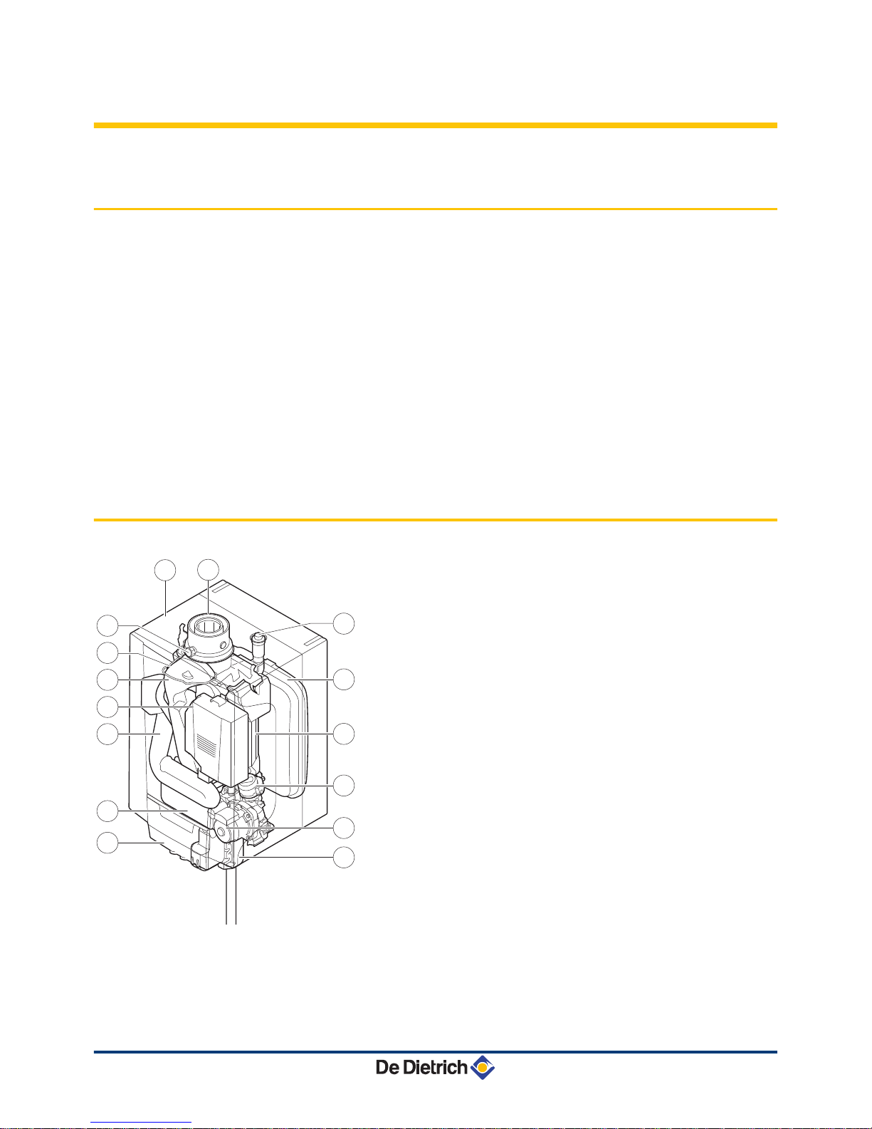
3.2 Main parts
1
Flue gas outlet/Air intake
2
Casing/air box
3
Outlet for measuring combustion gases
4
Ignition/ionization electrode
5
Flue gas discharge pipe
6
Gas/air system with a fan, gas block and automatic burner
unit
7
Air intake silencer
8
Plate heat exchanger (DHW) (Only on models with
domestic hot water production
)
9
Connection box
10
Siphon
11
Shunt pump
12
3-way valve
13
Heat exchanger (Central heating)
14
Expansion vessel
15
Automatic air vent
T004783-A
3
5
6
7
9
8
13
12
14
15
11
10
1
2
4
EMC-M 24 EMC-M 24/28 MI EMC-M 30/35 MI EMC-M 34/39 MI 3. Technical description
210212 - 7601972-03
11
Page 14

3.3 Skeleton Diagrams
EMC-M 24
1
Heat exchanger (Central heating)
2
Safety valve
3
Heating flow (Primary circuit)
4
Heating flow (Secondary circuit)
5
Heating return (Secondary circuit)
6
Heating return (Primary circuit)
7
3-way valve
8
Shunt pump (Central heating)
EMC-M 24/28 MI - 30/35 MI - 34/39 MI
1
Heat exchanger (Central heating)
2
Hydroblock
3
Plate heat exchanger (DHW)
4
Safety valve
5
Heating flow
6
Domestic hot water outlet (DHW)
7
Domestic cold water inlet
8
Heating return
9
Shunt pump (Central heating)
10
3-way valve
3.4 Operating principle
3.4.1. Regulation of the water temperature
The boiler is fitted with an electronic temperature regulator having an
outlet
and return temperature probe. The flow temperature can be set
between 20°C and 90°C. The boiler reduces its power when the set
outlet-temperature is attained. The cutout temperature is the set
heating outlet-temperature + 5 °C.
T003806-A
3 4 5 6
1
2
8
7
T003393-D
5 6 7 8
1
2
3
4
10
9
3. Technical description EMC-M 24 EMC-M 24/28 MI EMC-M 30/35 MI EMC-M 34/39 MI
12
210212 - 7601972-03
Page 15
3.4.2. Protection against a shortage of water
The boiler is fitted with a safety device to prevent the shortage of water
based on temperature measurements.
By reducing its output when
the water flow rate is in danger of becoming insufficient, the boiler
continues to operate as long as possible. In case of insufficient ΔT
≥ 50°C flow or an excessive increase in flow temperature, the boiler
will enter shutdown mode for 10 minutes. When there is no water in
the boiler, or if the pump is not running, the system is locked
(breakdown)
In the event of a fault, the status signal for the B
button on
the connection box flashes red.
¼For more detailed information, see chapter:
"Shutdowns and
lock-outs", page 60.
3.4.3. Maximum temperature protection
The maximum temperature protection locks the boiler if the water
temperature becomes too high (
110°C).
In the event of a fault, the status signal for the B
button on
the connection box flashes red.
¼For more detailed information, see chapter:
"Shutdowns and
lock-outs", page 60.
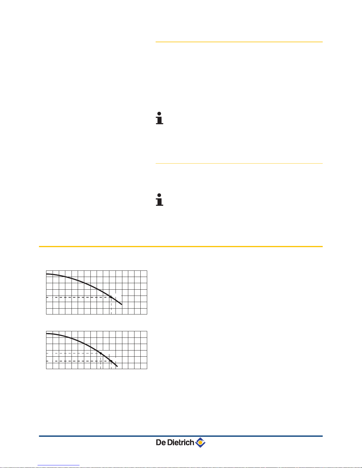
3.5 Circulating pump
The boiler is fitted with an on/off circulation pump.
EMC-M 24
H
Manometric height central heating circuit
Q
Water flow ( ΔT=20K)
EMC-M 24/28 MI
H
Manometric height central heating circuit
Q
Water flow ( ΔT=20K)
R000367-A
12001000600 800400200
0
0
100
200
300
400
500
600
Q (l/h)
16001400
700
H (mbar)
1030
24 kW
275
R000365-A
12001000600 800400200
0
0
100
200
300
400
500
600
H (mbar)
Q (l/h)
16001400
860
1030
20 kW
24 kW
253
127
EMC-M 24 EMC-M 24/28 MI EMC-M 30/35 MI EMC-M 34/39 MI 3. Technical description
210212 - 7601972-03
13
Page 16

EMC-M 30/35 MI - 34/39 MI
H
Manometric height central heating circuit
Q
Water flow ( ΔT=20K)
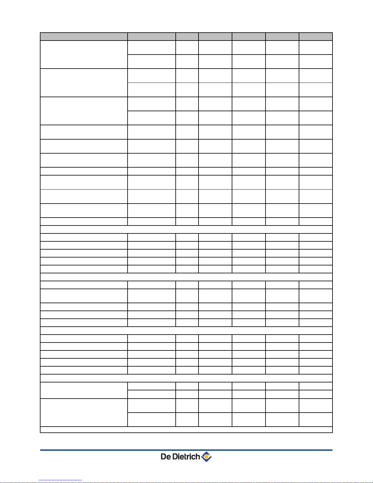
3.6 Technical specifications
Boiler type EMC- M
24 24/28 MI 30/35 MI 34/39 MI
General
EC indentification no. PIN
0063CM3019
Flow rate setting Adjustable
Modulating, Start/Stop
Nominal output (Pn)
Heating System (80/60 °C)
minimummaximum
kW 5,5 - 23,4 5,5 - 23,4 7,7 - 29,2 7,7 - 33,8
Factory setting kW 23,4 19,5 29,2 29,1
Nominal output (Pn)
Heating System (50/30 °C)
minimummaximum
kW 6,1 - 24,8 6,1 - 24,8 8,5 - 31,0 8,5 - 35,7
Factory setting kW 24,8 20,7 31,0 30,7
Nominal output (Pn)
DHW System
minimum maximum
kW - 5,5 - 27,5 7,7 - 33,9 7,7 - 37,8
Factory setting kW - 27,5 33,9 37,8
Nominal input (Qn)
Heating System (Hi)
minimum maximum
kW 5,6 - 24,0 5,6 - 24,0 7,8 - 30,0 7,8 - 34,9
Factory setting kW 24,0 20,0 30,0 30,0
Nominal input (Qn)
Heating System (Hs)
minimum maximum
kW 6,2 - 26,7 6,2 - 26,7
8,7 - 33,3 8,7 - 38,8
Factory setting kW 26,7 22,2 33,3 33,3
Nominal input (Qnw)
DHW System (Hi)
minimummaximum
kW -
5,6 - 28,2 7,8 - 34,9 7,8 - 39
Nominal input (Qnw)
DHW System (Hs)
minimummaximum
kW -
6,2 - 31,3 8,7 - 38,8 8,7 - 43,3
Nominal input (Qn)
Propane (Hi)
minimum kW
7,1 7,1 10 10
Nominal input (Qn)
Propane (Hs)
minimum kW
7,7 7,7 10,9 10,9
Heating efficiency under full load
(Hi) (80/60 °C)
- % 97,6 97,6 97,2 96,9
Heating efficiency under full load
(Hi) (50/30 °C)
- % 103,3 103,3 103,3 102,4
Heating efficiency under partial load
(Hi) (Return temperature 60
°C)
- % 97,8 97,8 98,4 98,4
Heating efficiency under partial load
(Hi) (92/42 EEG)
(Return temperature 30
°C)
- % 109,2 109,2 108,8 108,8
Data on the gases and combustion gases
Equipment categories
- II
2ESi3P
Type of air/flue gas connection
B23, B
23P
, B33, C
13x
, C
33x
, C
43x
, C53, C
63x
, C
83x
, C
93x
(1) Front panel removed
R000368-A
12001000600 800400200
0
0
100
200
300
400
500
600
Q (l/h)
16001400
700
H (mbar)
1250
30 kW
317
187
1500
35 kW
3. Technical description EMC-M 24 EMC-M 24/28 MI EMC-M 30/35 MI EMC-M 34/39 MI
14
210212 - 7601972-03
Page 17
Boiler type EMC- M
24 24/28 MI 30/35 MI 34/39 MI
Gas inlet pressure G20 (Gas H) minimum-
maximum
mbar 17 - 30 17 - 30 17 - 30 17 - 30
Connecting
pressure
mbar 20 20 20 20
Gas inlet pressure G25 (Gas L) minimum-
maximum
mbar 20 - 30 20 - 30 20 - 30 20 - 30
Connecting
pressure
mbar 25 25 25 25
Gas inlet pressure G31 (Propane) minimum-
maximum
mbar 30- 50 30- 50 30- 50 30- 50
Connecting
pressure
mbar 37 37 37 37
Gas consumption G20 (Gas H) minimum-
maximum
m3/h
0,59 - 2,54 0,59 - 2,98 0,83 - 3,68 0,83 - 4,13
Gas consumption G25 (Gas L) minimum-
maximum
m3/h
0,69 - 2,95 0,69 - 3,47 0,96 - 4,28 0,96 - 4,80
Gas consumption G31 (Propane) minimum-
maximum
m3/h
0,29 - 0,98 0,29 - 1,15 0,41 - 1,42 0,41 - 1,47
NOx annual emission (n=1)
mg/kWh 58 58 52 56
NOx classification (EN 297 pr A3, EN
483)
5 5 5 5
Mass flue gas flow rate minimum-
maximum
kg/h
9,4 - 38,7 9,4 - 45,5 13,1 - 56,2 13,1 - 62,9
Flue gas temperature minimum-
maximum
°C
32 - 78 32 - 84 31 - 82 31 - 86
Maximum counter pressure
Pa 80 116 105 120
Characteristics of the heating circuit
Water content
l 1,4 1,6 1,7 1,7
Water operating pressure minimum bar 0,8 0,8 0,8 0,8
Water operating pressure (PMS) maximum bar 3,0 3,0 3,0 3,0
Water temperature maximum °C 110 110 110 110
Operating temperature maximum °C 90 90 90 90
Characteristics of the domestic hot water circuit
Specific hot water flow (∆T = 30K)
l/min - 14 17 19
Domestic water resistance (without
flow restrictor)
mbar - 123 215 260
Flow rate threshold minimum l/min - 1,2 1,2 1,2
Water content
l - 0,16 0,18 0,18
Operating pressure (Pmw) maximum bar - 8 8 8
Electrical characteristics
Power supply voltage
VAC 230 230 230 230
Power consumption Full load maximum W 117 117 145 159
Power consumption Part load maximum W 96 82 101 101
Power consumption - Standby maximum W 3 3 3 3
Electrical protection index
IP X4D X4D X4D X4D
Other characteristics
Weight (empty)
Total kg 24,5 26 28,5 28,5
Mounting
(1)
kg 23 24 27 27
Acoustic level at 1 metre
maximum Heating
System
dB(A) 40 38 42 42
maximum DHW
System
dB(A) _ 42 45 46
(1) Front panel removed
EMC-M 24 EMC-M 24/28 MI EMC-M 30/35 MI EMC-M 34/39 MI 3. Technical description
210212 - 7601972-03
15
Page 18
4 Installation
4.1 Regulations governing installation
WARNING
Installation of the appliance must be done by a qualified
engineer in accordance with prevailing local and national
regulations.
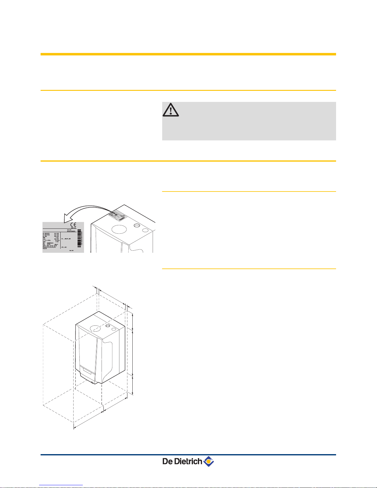
4.2 Choice of the location
4.2.1. Data plate
The identification plate on top of the boiler features the boiler serial
number and important boiler specifications, for example the model
and unit category. The dF and dU codes are also stated on the type
plate.
4.2.2.
Location of the boiler
4 Before mounting the boiler, decide on the ideal position for
mounting, bearing the Directives and the dimensions of the
appliance in mind.
4 When choosing the position for mounting the boiler, bear in mind
the authorised position of the combustion gas discharge outlets
and the air intake opening.
4 Make sure there is enough room underneath the boiler for the
connection box.
4 To ensure adequate accessibility to the appliance and facilitate
maintenance, leave enough space around the boiler.
4 Mount the boiler onto a flat surface.
R000292-A
R000424-A
368
5
1000
364
≥ 200
5
≥ 250
554
4. Installation EMC-M 24 EMC-M 24/28 MI EMC-M 30/35 MI EMC-M 34/39 MI
16
210212 - 7601972-03
Page 19
WARNING
4 Fix the appliance to a solid wall capable of bearing
the weight of the appliance when full of water and fully
equipped.
4 Do not place the appliance above a heat source or a
cooking appliance.
4 Do not locate the boiler in direct or indirect sunlight.
4 It is forbidden to store inflammable products and
materials in the boiler room or close to the boiler,
even temporarily.
CAUTION
4 The boiler must be installed in a frost-free
environment.
4 An earthed electrical connection must be available
close to the boiler.
4 A connection to the mains drainage system for the
discharge of condensate must be available close to
the boiler.
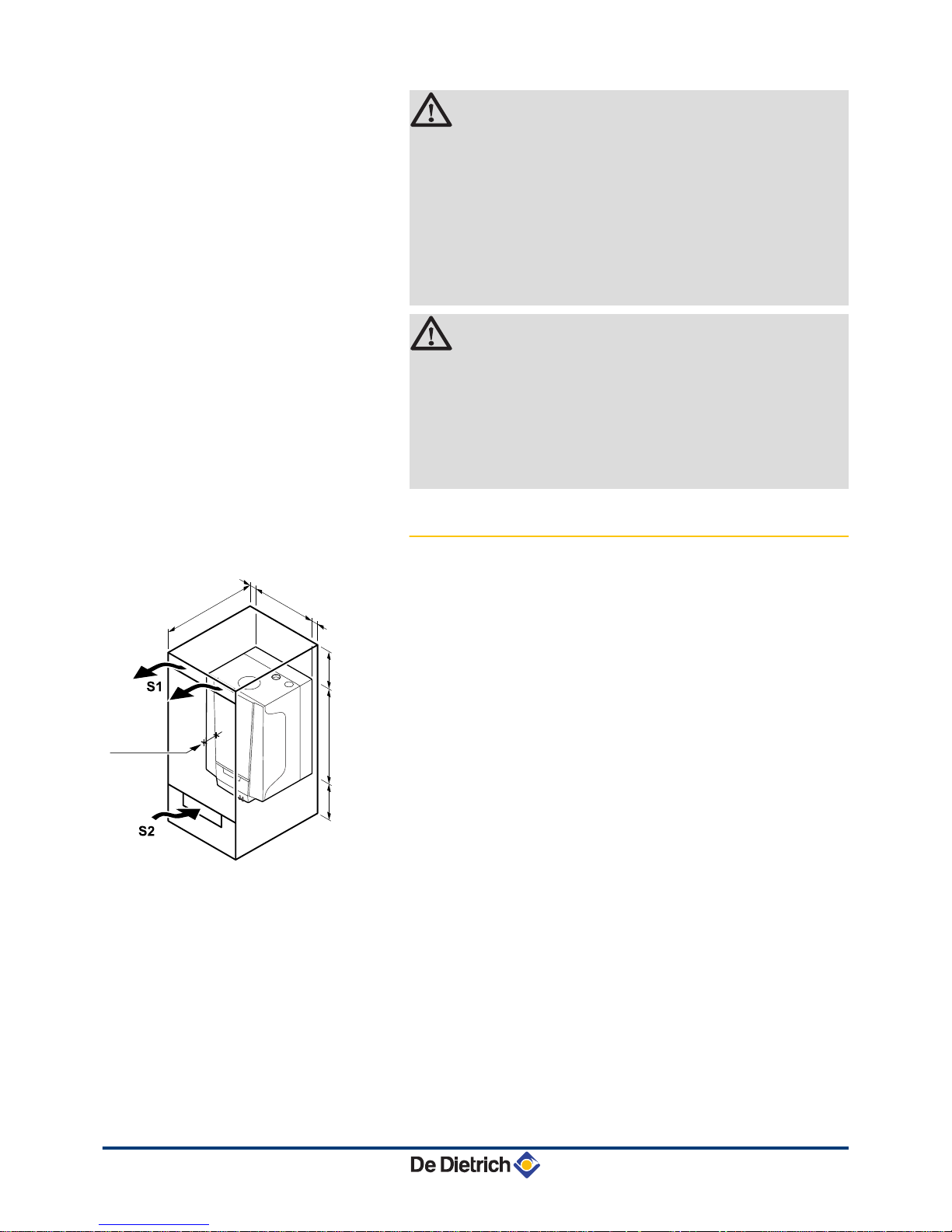
4.2.3. Ventilation
(1)
Distance between the front of the boiler and the internal
wall of the casing box.
If the boiler is installed in a closed casing, respect the minimum
dimensions given in the diagram opposite.
Also allow openings to
obviate the following hazards:
4 Accumulation of gas
4 Heating of the box
Minimum cross section of the openings: S1 + S2 = 150 cm
2
R000421-A
368
5
5
≥ 250
≥ 250
554
≥ 464
≥
100
(1)
EMC-M 24 EMC-M 24/28 MI EMC-M 30/35 MI EMC-M 34/39 MI 4. Installation
210212 - 7601972-03
17
Page 20

4.3 Main dimensions
i
Connection of the combustion gas exhaust pipe; Ø 60 mm
h
Connection of the air intake pipe; Ø 100 mm
ê
Safety valve outlet pipe; Ø 15 mm
j
Condensates discharge; Ø 25 mm
{
Heating circuit flow; G¾"
y
Domestic hot water outlet; G½"
Gas /
Gaz
Gas connection; G½"
x
Domestic cold water inlet; G½"
z
Heating circuit return; G¾"
R000354-A
368
184
364
243
541
209
230
664
151
35
52
1
2
3
4
1
= 117
2
= 184
3
= 251
4
= 316
46
90
187
76
4. Installation EMC-M 24 EMC-M 24/28 MI EMC-M 30/35 MI EMC-M 34/39 MI
18
210212 - 7601972-03
Page 21
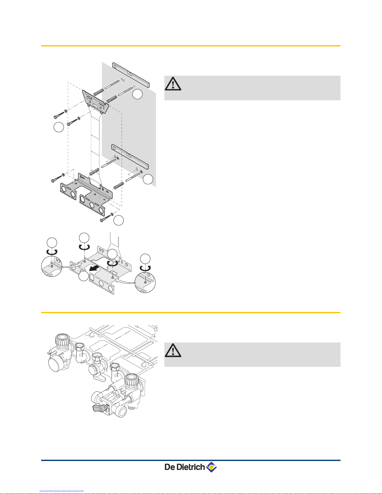
4.4 Installing the mounting frame
1. Drill 2 holes with Ø 10 mm for the lower part of the mounting
frame. Put the plugs in place.
CAUTION
Make sure that all the drill holes are level.
2. Affix
the lower part of the mounting frame to the wall using 2 of the
screws supplied.
3. Open out the mounting frame and mark out the 2 drill holes for the
upper part of the mounting frame on the wall. Drill 2 holes with a
Ø of 10 mm. Put the plugs in place.
4. Affix the upper part of the mounting frame to the wall using 2 of
the screws supplied.
5. Extend the mounting frame to its maximum depth to install a boiler
with a built-in expansion vessel. To do so, remove the plastic
screws from the lower bracket, and once it has been extended,
replace the screws to fix the mounting frame.
4.5 Positioning the boiler
1. Remove the protective caps from all of the hydraulic inlets and
outlets on the boiler.
CAUTION
The cock from the filling loop must be closed.
2. Fit a fibre gasket to each joint on the valve plate.
T003395-F
1
2
3
4
R000419-A
3
2
3
1
1
T002375-D
EMC-M 24 EMC-M 24/28 MI EMC-M 30/35 MI EMC-M 34/39 MI 4. Installation
210212 - 7601972-03
19
Page 22
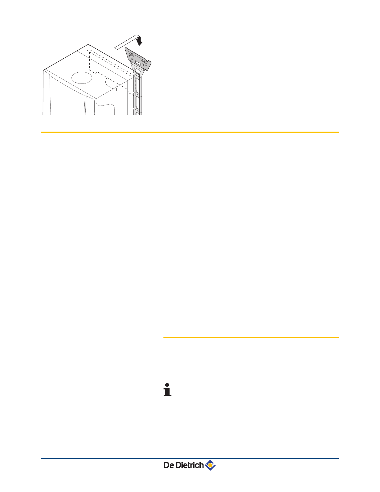
3. Position the boiler above the plumbing fixtures plate and locate it
against the mounting frame. Gently lower the boiler.
Mount the
boiler using the suspension bracket on the back of the boiler.
4. Tighten the valve nuts on the boiler.
4.6 Hydraulic connections
4.6.1. Flushing the system
Installation must be carried out in accordance with the prevailing
regulations,
the codes of practice and the recommendations in these
instructions.
Installing the boiler in new installations (installations less than
6 months old)
4 Clean the installation with a universal cleaner to eliminate debris
from the appliance (copper, hemp, flux).
4 Thoroughly flush the installation until the water runs clear and
shows no impurities.
Installing the boiler in existing installations
4 Remove sludge from the installation.
4 Flush the installation.
4 Clean the installation with a universal cleaner to eliminate debris
from the appliance (copper, hemp, flux).
4 Thoroughly flush the installation until the water runs clear and
shows no impurities.
4.6.2. Water flow rate
The boiler’s modulating control system limits the maximum difference
in
temperature between the heating flow and return and the maximum
speed at which the flow temperature increases. In this way, the boiler
does not require a minimum water flow rate.
If using a heating and domestic hot water production type
boiler on an installation in which the flow can be fully
disconnected from the return (e.g. by using thermostatic
valves), you should either fit a bypass or fit an expansion
vessel to the heating flow conduit.
R000420-A
4. Installation EMC-M 24 EMC-M 24/28 MI EMC-M 30/35 MI EMC-M 34/39 MI
20
210212 - 7601972-03
Page 23
4.6.3. Connection of the heating circuit
1. Connect the heating water return pipe to the heating return
connection z.
2.
Connect the heating water outlet pipe to the heating flow
connection {.
CAUTION
4 The heating pipe must be mounted in accordance
with prevailing provisions.
4 Carry out any welding work required at a safe
distance from the boiler or before the boiler is fitted
.
4 Install a drain under the safety valve leading to the
sewage system ê.
4.6.4. Connection of the water circuit for
domestic use
1. Connect the cold water inlet pipe to the domestic cold water
connection k.
2.
Connect the domestic hot water outlet pipe to the domestic hot
water connection m.
CAUTION
4 The domestic water pipes must be connected in
accordance with prevailing provisions.
4 Carry out any welding work required at a safe
distance from the boiler or before the boiler is fitted
.
4 If using synthetic pipes, follow the manufacturer’s
(connection) instructions.
4.6.5. Connecting the expansion vessel
The boiler is fitted as standard with an 8-litre expansion vessel.
If
the water volume is greater than 100 litres or the static height of the
system exceeds 5 metres, an additional expansion vessel must be
fitted. Refer to the table below to determine the expansion vessel
required for the installation.
Conditions of validity of the table:
4 3-bar safety valve
4 Average water temperature: 70 °C
Flow temperature: 80 °C
Return temperature: 60 °C
4 The filling pressure in the system is lower than or equal to the initial
pressure in the expansion vessel
EMC-M 24 EMC-M 24/28 MI EMC-M 30/35 MI EMC-M 34/39 MI 4. Installation
210212 - 7601972-03
21
Page 24
Initial pressure of the
expansion vessel
Volume of the expansion vessel depending on the volume of the installation (in litres)
100 125 150 175 200 250 300 > 300
0.5 bar 4,8 6,0 7,2 8,4 9,6 12,0 14,4 Volume of the installation x 0,048
1 bar
8,0
(1)
10,0 12,0 14,0 16,0 20,0 24,0 Volume of the installation x 0,080
1.5 bar 13,3 16,6 20,0 23,3 26,6 33,3 39,9 Volume of the installationx 0,133
(1) Factory configuration
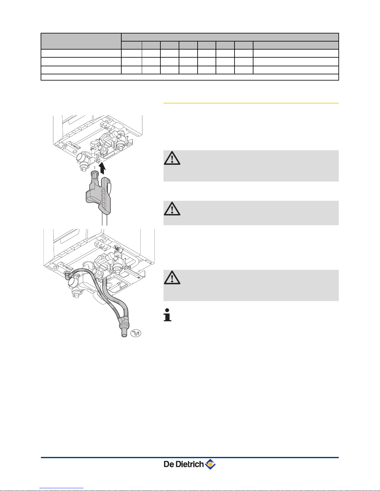
4.6.6. Connecting
the condensate discharge pipe
The syphon is supplied separately as standard with the boiler
(Includes flexible plastic drain hose
). Fit these parts underneath the
boiler. To do this, proceed as follows:
1. Fill the syphon with water up to the mark.
CAUTION
Fill the water siphon before starting the boiler to avoid
combustion products escaping from the boiler.
2.
Press the syphon firmly into the j opening provided for it
underneath the boiler.
The syphon must click into place.
CAUTION
Check whether the syphon is solidly fitted in the boiler.
3. Mount
a standard drainage pipe, Ø 32 mm or more, leading to the
mains drainage system.
4. Mount the flow collector.
5.
Insert the hoses from the siphon drain j and safety valve ê.
6. Mount a trap or a siphon in the discharge pipe.
CAUTION
Do not make a fixed connection owing to maintenance
work on the siphon.
4 Do
not plug the condensate discharge pipe. Make an
open connection with the drain.
4 Set the discharge pipe at a gradient of at least 30 mm
per metre, maximum horizontal length 5 metres.
4 Do not drain condensation water into a roof gutter at
any time.
4 Connect the condensate discharge pipe in
accordance with prevailing standards.
T004860-B
T004868-D
4. Installation EMC-M 24 EMC-M 24/28 MI EMC-M 30/35 MI EMC-M 34/39 MI
22
210212 - 7601972-03
Page 25

4.6.7. Automatic air bleed
Check that the automatic bleed valve is open: This is visible on the
right on top of the boiler. If necessary, the air vent can be closed off
with the cap that can be found next to it.
4.7
Gas connection
1. Connect the gas inlet pipe GAS / GAZ.
2.
Connect the gas pipe to the gas shut off valve.
The diameters of the pipes must be defined in accordance
with the standards in force in your country.
WARNING
4 Close the main gas valve before starting work on the
gas pipes.
4 Before mounting, check that the gas meter has
sufficient capacity. To do this, you should keep in
mind the consumption of all domestic appliances.
4 If the gas meter has a too low capacity, inform the
energy supply company.
CAUTION
4 Connect the gas pipe in accordance with prevailing
standards and regulations.
4 Carry out any welding work required at a safe
distance from the boiler or before the boiler is fitted.
4 Ensure
that there is no dust in the gas pipe. Blow into
the pipe or shake it before mounting.
4 We recommend installing a gas filter on the gas pipe
to prevent clogging of the gas valve unit.
R000350-A
EMC-M 24 EMC-M 24/28 MI EMC-M 30/35 MI EMC-M 34/39 MI 4. Installation
210212 - 7601972-03
23
Page 26

4.8 Flue gas system connections
4.8.1. Classification
9
4
2
22
4
4
3
6 8
5
5
5
7
7
7
C
33(x)
C
33(x)
C
43(x)
C
83(x)
C
43(x)
C
43(x)
C
13(x)
C
53
C
83(x)
C
83(x)
C
33(x)
B
23P
B
23P
C
93(x)
C
93(x)
1
1
B
33
B
33
C002339-C
1
Configuration B
33
Connection to a collective pipe via a concentric pipe
(combustive air taken from the boiler room
)
All of the pressurised parts of the appliance are
surrounded by air.
2
Configuration B23 - B
23P
Connection to a chimney using a connection kit
(combustive air taken from the boiler room
)
3
Configuration C
13(x)
Air/flue
gas connection by means of concentric pipes to a
horizontal terminal (so-called forced flue)
4
Configuration C
33(x)
Air/flue
gas connection by means of concentric pipes to a
vertical terminal (roof outlet)
5
Configuration C
43(x)
Air/flue gas connection to a collective conduit for
watertight boilers (3CE P
system)
6
Configuration C
53
Air and flue gas connection separated by means of a biflow
adapter and single pipes (combustive air taken from
outside)
7
Configuration C
83(x)
Flue gas connection to a collective conduit for sealed
boilers. The air supply is individual via a terminal coming
from outside the building
.
4. Installation EMC-M 24 EMC-M 24/28 MI EMC-M 30/35 MI EMC-M 34/39 MI
24
210212 - 7601972-03
Page 27

8
Configuration C
93(x)
Air/flue gas connection by concentric pipes in the boiler
room and single pipes in the chimney (combustive air in
counter current in the chimney)
9
Configuration C
93(x)
Air/flue gas connection by concentric pipes in the boiler
room and single flex in the chimney (combustive air in
counter current in the chimney)
WARNING
4 Only
factory components are authorised for
connecting the boiler and the terminal.
4 The clear section must comply with the
standard.
4 The chimney must be swept before the
installation of the evacuation conduit.
4.8.2. Lengths of the air/flue gas pipes
For configurations B23 and C93, the lengths given in the
table are valid for horizontal conduits with a maximum
length of 1 metre. For each additional metre of horizontal
conduit, subtract 1.2 m from the vertical length Lmax
Type of air/flue gas connection Diameter Maximum length in metres
EMC-M
24 24/28 MI 30/35 MI 34/39 MI
C13Concentric pipes connected to a
horizontal terminal
Alu or PPS 60/100 mm 7,0 7,0 3,0 3,0
80/125 mm 21,5 25,5 11,5 9,5
C33Concentric pipes connected to a
vertical terminal
Alu or PPS 60/100 mm 2,5 3,0 - -
80/125 mm 19,5 24,0 13,5 11,5
C93Concentric pipes in the boiler room
Single conduits in the chimney
(combustive air in counter-current)
Alu or PPS 80/125 mm
80 mm (Rigid duct)
18,0 23,0 19,0 17,0
Concentric pipes in the boiler room
Flexible single conduit in the chimney
PPS 60/100 mm
80 mm (Flexible duct)
19,0 21,0 6,5 4,5
80/125 mm
80 mm (Flexible duct)
20,0 25,0 15,0 13,0
C53Bi-flow adapter and separate single
air/flue gas ducts (combustive air
taken from outside)
Alu 60/100 mm
2 x 80 mm
40,0 40,0 21,5 18,0
B23Chimney (rigid or flexible duct in
chimney, combustive air taken from
the premises)
PPS 80 mm (Rigid duct) 40,0 40,0 21,0 17,0
80 mm (Flexible duct) 31,0 32,0 13,0 10,0
C43Collective conduit for sealed boiler (3
CEP)
(1)
To determine the size of such a system, consult the supplier of the 3 CEP
conduit.
(1) The boiler’s parameter settings will need to be changed. ¼For more detailed information, see chapter:
"Changing the settings", page
45.
EMC-M 24 EMC-M 24/28 MI EMC-M 30/35 MI EMC-M 34/39 MI 4. Installation
210212 - 7601972-03
25
Page 28

WARNING
Maximum length = lengths of the straight air/flue gas ducts
+ equivalent lengths of other components
The max length in the flue gas pipe (configurations C93, B
23P
) of the
elbow bracket at the outlet must not exceed:
4 30 m for rigid PPS
4 25 m for flexible PPS
If
longer lengths are used, holding clamps must be added per sections
of 25 or 30 metres.
For the list of flue gas system accessories and the
equivalent lengths, refer to the current price list.
4.8.3. Additional Directives
4 Please refer to the manufacturer’s instructions for the material in
question when installing the flue gas discharge and air supply
materials.
If the flue gas discharge and air supply materials are not
installed according to the instructions (e.g. they are not leakproof,
not clamped in place etc.), this may cause hazardous situations
and/or result in bodily injury. After assembly, check at least all flue
gas and air–carrying parts for tightness.
4 Connection of the combustion gas exhaust directly to the buildings
brick chimneys or flues is forbidden for condensation reasons.
4 Always clean the ducts thoroughly in cases where lining pipes are
used and/or a connection of the air-supply.
4 It must be possible to inspect the flue or chimney.
4 In cases where condensate coming from the stainless steel or
plastic sections of the flue gas pipe can be driven back towards
the aluminium section, this condensate must be removed using a
collecting device before the aluminium section is reached.
4 For long, aluminium, combustion-gas exhaust pipes it is initially
necessary to consider the relatively high quantity of corrosive
products which are brought together with the condensate from the
exhaust pipe. The siphon on the equipment requires regular
cleaning or, preferably, an additional condensate collector can be
installed above the equipment.
4 The combusted gas discharge pipe must be sufficiently inclined
towards the boiler (at least 50 mm per metre) and an adequate
condensate collection tank and discharge system constructed (at
least 1 m before the boiler opening). The elbows fitted must be at
more than 90° to guarantee the provision of an adequate gradient
and tightness on the lip rings.
Please contact us for further information.
4. Installation EMC-M 24 EMC-M 24/28 MI EMC-M 30/35 MI EMC-M 34/39 MI
26
210212 - 7601972-03
Page 29

4.9 Electrical connections
4.9.1. Control unit
The boiler is not line- and neutral sensitive. The control unit is fully
integrated with the fan, venturi and gas block.
The boiler is fully prewired. The PCB has a connection to the connection box with
instrument panel, via the HMI connector. The PCB has a RS232
connection for a PC/laptop via the RS232 connector. The main
characteristics of the control unit are described in the table below.
Power supply voltage
230 VAC/50Hz
Fuse rating F1 (230 VAC) 1,6 AT
The boiler is fitted with a 3-wire power supply cable (cable length 1,5
m) suitable for a 230VAC/50Hz
power supply with phase/neutral/
earth system. The power supply cable is connected to the MAINS
connector. A spare fuse can be found in the housing of the control
system.
WARNING
Use an isolating transformer for connection values other
than those stated above.
CAUTION
4 When the power supply cable has to be replaced, it
must be ordered from DeDietrich. The power supply
cable should only be replaced by DeDietrich, or by
an installer certified by DeDietrich.
4 The switch must be easily accessible
4.9.2. Recommendations
WARNING
4 Only
qualified professionnals may carry out electrical
connections, always with the power off.
4 The boiler is entirely pre-wired. Do not modify the
connections inside the control panel.
4 Earth the appliance before making any electrical
connections.
Make the electrical connections of the boiler according to:
4 The instructions of the prevailing standards.
4 The instructions on the electrical diagrams provided with the
boiler.
4 The recommendations in the instructions.
EMC-M 24 EMC-M 24/28 MI EMC-M 30/35 MI EMC-M 34/39 MI 4. Installation
210212 - 7601972-03
27
Page 30

CAUTION
4 Separate the sensor cables from the 230 V cables.
4 Outside the boiler: Use 2 pipes or cable guides at
least 10 cm apart.
4.9.3. PC/Laptop connection
The PCB for the automatic control unit has a RS232
connection for a
PC/laptop via the RS232 connector (This connection is therefore not
in the connection box). Using the Recom service software, you can
enter, change and read out various boiler settings.
4.9.4. Connecting service tool
The PCB for the automatic control unit has a HMI connection. This
connection is used to connect the control panel for the boiler.
Connector HMI is also used to connect the service tool
(Accessory).
Herewith various settings can be imported, changed and exported.
For example:
4 Temperature display.
4 Number of operating hours.
4 State boiler.
4 Parameter settings.
For the installation or mounting of any accessories, refer to
the
mounting instructions delivered with the accessories in
question.
T005415-A
T005416-A
4. Installation EMC-M 24 EMC-M 24/28 MI EMC-M 30/35 MI EMC-M 34/39 MI
28
210212 - 7601972-03
Page 31

4.9.5. Access to the connector block
The connection box with instrument panel is supplied separately as
standard
with this unit. The connection box must be connected to the
automatic control unit using the cable supplied. To do this, proceed
as follows:
The cable with the plug from the automatic control unit exits
underneath the boiler.
1. Carefully
open the latch on the rear of the connection box using a
screwdriver.
2. Open the cover of the connection box.
3. Disconnect a pull relief clip. Turn the pull relief clip round.
4. Insert the plug from the cable into the HMI plug on the PCB for the
connection box.
5. Press the pull relief clip firmly into place.
6. Now connect the required external controllers to the remaining
connectors. To do this, proceed as follows:
- Disconnect a pull relief clip.
- Turn the pull relief clip round.
- Place the cable underneath the pull relief clip.
- Press the pull relief clip firmly into place.
- Connect the connection box and check that the box is sealed
properly.
7. Slide the User instruction card supplied into the guides underneath
the connection box.
8. Slide the connection box into the guides underneath the boiler
once all the connections have been made.
9. Secure the connection box using the screw found in the guides.
The connection box can also be attached to the wall using
the screw holes on the back of the connection box.
The
connection box should be screwed to the wall using the
point indicated inside it.
The connection options for the PCB are explained in the following
paragraphs.
4.9.6.
Connection options
Various thermostats and controllers can be connected to the control
PCB:
n
Connecting modulating controller
The boiler is fitted with a OpenTherm connection as standard.
As a result, modulating OpenTherm controllers can be connected
without further modifications.
The boiler is also suitable for
OpenTherm Smart Power.
4 In the case of a room temperature controller or a controller with
room temperature compensation, fit the controller in a reference
area (generally the living room).
R000411-B
8
9
7
6
4
SCU HMI OT
On/ofBUS BUS
5
3
2
1
R000450-A
1234 56 34 12 12123
On/off
OT
Enable
+ - + -
CH
DHW
Status
Nc
C No
Tout
Tdhw
BL
SCU
BUS
BUS
HMI
EMC-M 24 EMC-M 24/28 MI EMC-M 30/35 MI EMC-M 34/39 MI 4. Installation
210212 - 7601972-03
29
Page 32

4 Connect the two-wire cable to terminals On/off-OT of the
connector.
4 The boiler can also be put into operation without a controller.
To
do so, connect the bridge (supplied) to the terminals On/off-OT of
the connector.
n
Connect on/off thermostat
The boiler is suitable for connecting a 2 wire on/off room thermostat
or weather compensator.
4 In the case of a room temperature controller or a controller with
room temperature compensation, fit the controller in a reference
area (generally the living room).
4 Connect the 2 wire room thermostat to the On/off-OT terminals
of the connector.
4 The boiler can also be put into operation without a controller. To
do so, connect the bridge (supplied) to the terminals On/off-OT of
the connector.
n
Connecting the outside temperature sensor
4 An outside sensor can be connected to the Tout terminals of the
connector. In the case of an on/off thermostat, the boiler will
control the temperature with the set point from the internal heating
curve.
4 The boiler can also be put into operation without a controller. To
do so, connect the bridge (supplied) to the terminals On/off-OT of
the connector. In this case the boiler will control the temperature
with the set point from the internal heating curve.
CAUTION
Check whether the outside sensor is suitable for this
boiler. A suitable outside sensor can be obtained as an
accessory.
A OpenTherm controller can also use this outside sensor.
The heating curve required must then be set on the
controller.
Heating curve setting
If
an outside temperature sensor is connected, it is possible to adapt
the heating curve. The setting can be modified using parameters
p1, p"5, p"6 and p"7.
R000450-A
1234 56 34 12 12123
On/off
OT
Enable
+ - + -
CH
DHW
Status
Nc
C No
Tout
Tdhw
BL
SCU
BUS
BUS
HMI
R000451-A
1234 56 34 12 12123
On/off
O
T
Enable
+ - + -
C
H
DHW
Status
N
c
C No
Tout
Tdhw
BL
SCU
BUS
BUS
HMI
R000038-A
0 10 20
-20
-10
10
30
70
50
90
F
4. Installation EMC-M 24 EMC-M 24/28 MI EMC-M 30/35 MI EMC-M 34/39 MI
30
210212 - 7601972-03
Page 33

n
Connect frost protection
Frost protection in combination with on/off thermostat
If an on/off thermostat is used, it is advisable to protect any rooms
where there is risk of frost by using a frost thermostat. The radiator
valve
in a room where there is a risk of frost must, however, be open.
4 In rooms where there is a risk of frost, a frost thermostat (Tv)
should preferably be installed.
4 Connect the frost thermostat in parallel with an on/off room
thermostat (Tk) to the On/off-OT terminals of the connector.
When using a OpenTherm thermostat, a frost thermostat
cannot be connected in parallel to the On/off - OT
terminals.
Implement frost protection for the central heating
system in combination with an external sensor.
Frost protection in combination with an outside sensor
The central heating system can also be protected against frost in
combination with an outside sensor.
The radiator valve in a room
where there is a risk of frost must, however, be open. Connect the
outside sensor to the Tout terminals of the connector. The frost
protection functions as follows where an outside sensor is used:
4 At an outside temperature lower than -10°C (can be set with
parameter p30): the circulation pump switches on.
4 At an outside temperature higher than -10°C (can be set with
parameter p30): the circulation pump continues to run and then
switches off.
n
Connecting the calorifier sensor/thermostat
Connect the calorifier sensor or thermostat to the Tdhw terminals of
the connector.
n
Operation signal and failure signal (Status)
The alarm or operation signal is selected using parameter p40.
4 If the boiler is operating, the operation signal can be switched via
a potential-free contact (maximum 230 VAC, 1 A) on the No and
C terminals of the connector.
4 If the boiler locks out, the alarm can be transmitted via a potential-
free contact (maximum 230 VAC, 1 A) on the Nc and C terminals
of the connector.
4 The external 3-way valve (230 VAC, 1 A) can be used when
connecting an indirectly heated calorifier via a volt-free contact.
The neutral position of the three-way valve can be set using
parameter p34. The three-way valve is connected as follows:
- Nc = Central heating
R000450-A
1234 56 34 12 12123
On/off
OT
Enable
+ - + -
CH
DHW
Status
Nc
C No
Tout
Tdhw
BL
SCU
BUS
BUS
HMI
R000452-A
1234 56 34 12 12123
On/off
O
T
Enable
+ - + -
C
H
DHW
Status
N
c
C No
Tout
Tdhw
BL
SCU
BUS
BUS
HMI
R000453-A
1234 56 34 12 12123
On/off
O
T
Enable
+ - + -
C
H
DHW
Status
N
c
C No
Tout
Tdhw
BL
SCU
BUS
BUS
HMI
EMC-M 24 EMC-M 24/28 MI EMC-M 30/35 MI EMC-M 34/39 MI 4. Installation
210212 - 7601972-03
31
Page 34

- No = Domestic hot water
- C = Phase on
n
Connect on/off contact (Enable)
A
10-230 V signal can be connected to the CH and DHW connectors
to switch the production of heating water or sanitary warm water on
or off.
DANGER
If the power to the boiler is interrupted, a voltage will still
be present at connectors CH and DHW.
The production of heating water or domestic hot water is
switched on as standard.
The automatic control unit will
only respond to the switch and control the heating/
domestic hot water function once a 10-230 V signal has
been connected to the connectors. If the power to the boiler
is interrupted, the status of the CH and DHW input will be
reset to the factory setting (= enabled). Check whether this
is the status required.
n
Shutdown input
An
external gas pressure switch, for example, or a safety thermostat
for an underfloor heating unit can be connected to the BL
connector. This connection replaces the connection to the BL
connector.
CAUTION
The connection must be potential-free.
n
Connecting control panel
The control panel for the boiler is connected to connector BUS HMI.
¼See chapter: "Access to the connector block", page 29
n
Connections for optional control PCBs
Connector BUS SCU is used to communicate with optional control
PCBs. These control PCBs are used for a range of accessories.
For
the installation or mounting of any accessories, refer to the mounting
instructions delivered with the accessories in question.
R000454-A
1234 56 34 12 12123
On/off
O
T
Enable
+ - + -
C
H
DHW
Status
N
c
C No
Tout
Tdhw
BL
SCU
BUS
BUS
HMI
R000455-A
1234 56 34 12 12123
On/off
O
T
Enable
+ - + -
C
H
DHW
Status
N
c
C No
Tout
Tdhw
BL
SCU
BUS
BUS
HMI
R000448-A
1234 56 34 12 12123
On/off
O
T
Enable
+ - + -
C
H
DHW
Status
N
c
C No
Tout
Tdhw
BL
SCU
BUS
BUS
HMI
R000449-A
1234 56 34 12 12123
On/off
O
T
Enable
+ - + -
C
H
DHW
Status
N
c
C No
Tout
Tdhw
BL
SCU
BUS
BUS
HMI
4. Installation EMC-M 24 EMC-M 24/28 MI EMC-M 30/35 MI EMC-M 34/39 MI
32
210212 - 7601972-03
Page 35

4.10 Electrical diagram
R000291-A
P
230V, 50Hz
L N
MAINS
1 32
BR
BL
GN/
YW
PC
RS232
1
2
1
2
1
22
3 1
PSU
TATRFS
HL
6 7 8 9 10 11 12 131 2 3 5
SENSORS
E
IT
IT
HMI
MAINS
SENSORS
PUMP PWM
PUMP
3WV
RS232
PUMP
PUMP A
1 2 3
BK
BL
GN/
YW
3WV
3WV
1 2 3
BK
BL
BR
1 3 2
PUMP
1 2 3 4
BK BK
PWM
PU
MP
RS232
Connecting a computer
PUMP A
Shunt pump
TR
Return sensor
IT
Ignition transformer
3WV
3-way valve
TA
Flow sensor
E
Ignition/ionization electrode
HL
Safety thermostat
PSU
Storage parameter
P
Power supply
FS
Flow switch
HMI
Connection box
4.11 Filling the system
4.11.1. Water treatment
In most cases, the boiler and the central heating installation can be
filled
with normal tap water and no water treatment will be necessary.
WARNING
Do not add chemical products to the central heating water
without
first consulting a water treatment professional. For
example: antifreeze, water softeners, products to increase
or reduce the pH value, chemical additives and/or
inhibitors. These may cause faults in the boiler and
damage the heat exchanger.
Rinse the central heating installation with at least 3x the
volume of the central heating installation.
Flush the DHW
pipes with at least 20 times the volume of the pipes.
For an optimum functioning of the boiler, the water of the installation
must comply with following characteristics:
EMC-M 24 EMC-M 24/28 MI EMC-M 30/35 MI EMC-M 34/39 MI 4. Installation
210212 - 7601972-03
33
Page 36

Total installed heat output (kW)
≤ 70
70 - 200 200 - 550 > 550
Degree of acidity (water
non-treated)
pH 7 - 9 7 - 9 7 - 9 7 - 9
Degree of acidity (water
treated)
pH 7 - 8,5 7 - 8,5 7 - 8,5 7 - 8,5
Conductivity at 25°C µS/cm ≤ 800 ≤ 800 ≤ 800 ≤ 800
Chlorides mg/l ≤ 150 ≤ 150 ≤ 150 ≤ 150
Other components mg/l < 1 < 1 < 1 < 1
Total water hardness
(1)
°f 1 - 35 1 - 20 1 - 15 1 - 5
°dH 0,5 - 20,0 0,5 - 11,2 0,5 - 8,4 0,5 - 2,8
mmol/l 0,1 - 3,5 0,1 - 2,0 0,1 - 1,5 0,1 - 0,5
(1) For
installations that are heated at constant high temperatures with a total installed heat output; up to 200 kW a maximum total water hardness
of 8,4 °dH (1,5 mmol/l, 15 °f) applies and for above 200 kW a maximum total water hardness of 2,8 °dH (0,5 mmol/l, 5 °f) applies
If a water treatment is necessary, De Dietrich
Thermique recommends the following manufacturers:
4 Cillit
4 Climalife
4 Fernox
4 Permo
4 Sentinel
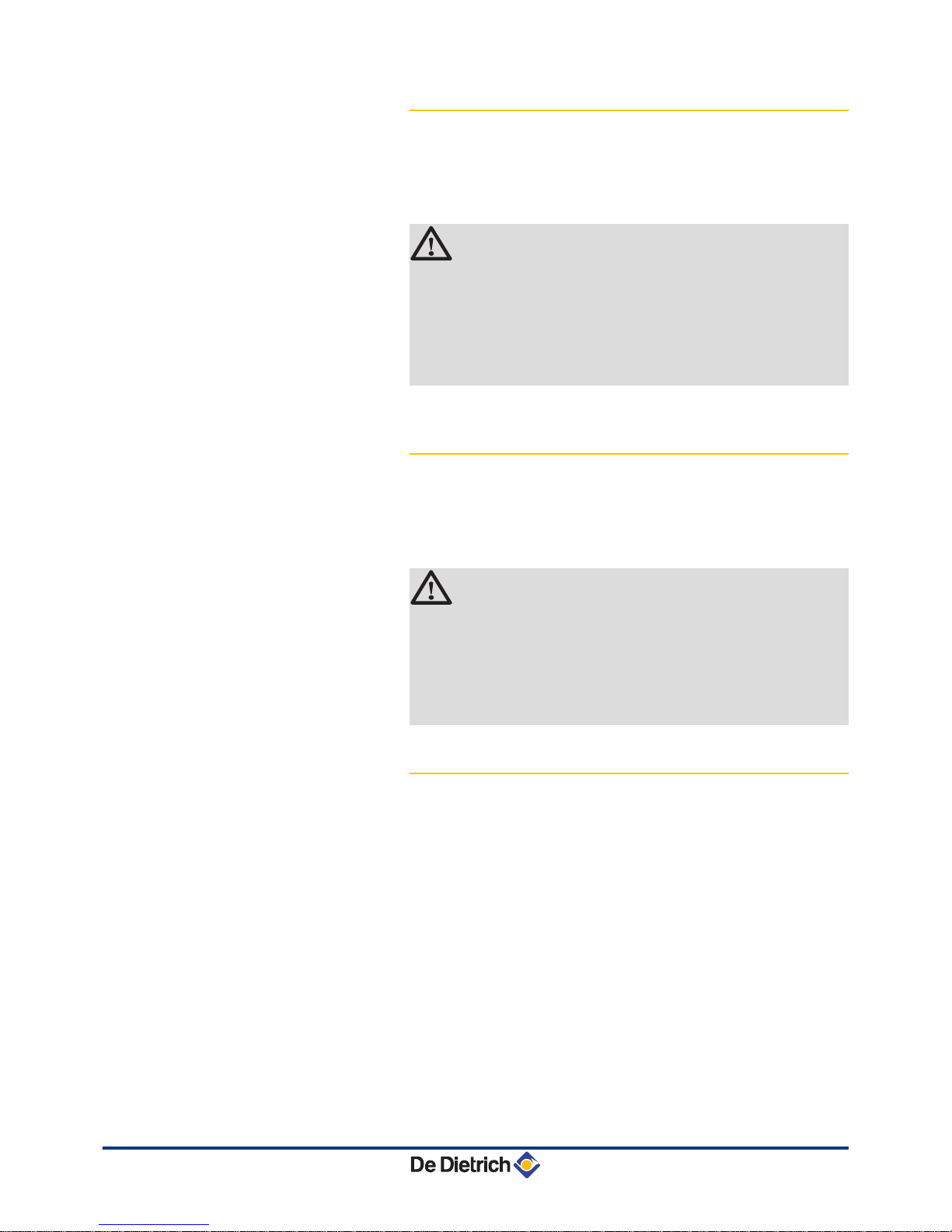
4.11.2. Filling the siphon
Check whether the syphon is filled up to the mark. If the syphon has
to be topped up, proceed as follows:
CAUTION
First remove the front housing of the boiler so that you can
disconnect the syphon.
¼See paragraph:
"Open the boiler", page 50
1. Move the lever underneath the hydroblock to the right to
disconnect the syphon.
2.
Remove the siphon and clean it.
3. Replace the seal ring for the syphon.
4. Fill the syphon with water up to the mark.
5.
Press the syphon firmly into the j opening provided for it
underneath the boiler. The syphon must click into place.
6. Check whether the syphon is solidly fitted in the boiler.
CAUTION
Fill the water siphon before starting the boiler to avoid
combustion products escaping from the boiler.
R000447-B
6
5
2
4
3
1
4. Installation EMC-M 24 EMC-M 24/28 MI EMC-M 30/35 MI EMC-M 34/39 MI
34
210212 - 7601972-03
Page 37

4.11.3. Filling the system
CAUTION
4 Before filling, open the valves on every radiator in the
installation.
4 Ensure that the boiler is switched off.
1. Open the central heating shut-off valves underneath the boiler.
2.
Open the cock from the filling loop (During filling, air can escape
from the system via the automatic air vent).
3. Turn off the tap on the filling loop if the pressure gauge indicates
a pressure between 1,5 and 2 bar.
4. Check the tightness of the water connections.
5. Turn the boiler on.
After the power is switched on, the boiler always runs
through an automatic venting programme lasting approx.
4 minutes (During filling, air can escape from the system
via the automatic air vent). If necessary, top up the water
level in the heating system (recommended hydraulic
pressure between 1,5 and 2 bar).
CAUTION
When venting, ensure that no water enters or makes
contact with the casing and electrical parts of the boiler.
4.11.4. Venting the system
It is essential that you bleed any air in the calorifier, the conduits or
the taps to prevent the annoying noises likely to be produced during
heating or when tapping water.
To do this, proceed as follows:
1. Open the valves on all radiators connected to the heating system.
2. Set the room thermostat as high as possible.
3. Wait until the radiators are hot.
4. Ensure that the boiler is switched off.
5. Wait around 10 minutes until the radiators are cold.
1
2
3
4
T000181-B
R000441-B
4
3
2
4
2
0 120
50
100
°C
bar
0
3
1
2
1
1
1
2
3
4
T000181-B
T000155-A
EMC-M 24 EMC-M 24/28 MI EMC-M 30/35 MI EMC-M 34/39 MI 4. Installation
210212 - 7601972-03
35
Page 38

6. Bleed the radiators. Start with the lower floors.
7.
Open the bleed connection using the bleed key provided whilst
keeping a rag pressed against the bleed connection.
CAUTION
The water may still be hot.
8. Wait until water comes out of the bleed valve and then close the
bleed connection.
9.
Turn the boiler on. A vent cycle of a duration of around 4 minutes
is carried out automatically.
10.After venting, check whether the pressure in the installation is still
sufficient.
If the water pressure is lower than 0,8 bar, more water
should
be added. If necessary, top up the water level in the
heating system (recommended hydraulic pressure
between 1,5 and 2,0 bar).
¼
See chapter: "Filling the system", page 35
11.Set the room thermostat or the regulator.
R000347-A
3
1
4
5
2
R000348-A
4. Installation EMC-M 24 EMC-M 24/28 MI EMC-M 30/35 MI EMC-M 34/39 MI
36
210212 - 7601972-03
Page 39

5 Commissioning
5.1 Connection box
5.1.1. Control panel
1
Sanitary hot water temperature rotary knob
2
Heating water temperature rotary knob
3
Sweep key B and Status signals
4
RESET-button and on/off signal
The instrument panel for the connection box has 2
push buttons with
signals. The signals provide information about the operating condition
of the boiler. The RESET button lights up green when the boiler is
connected to the mains. The status signal for the B button can flash
in a range of colours and at different frequencies. The meaning of
these signals can be found in the User instruction card supplied with
the boiler. ¼See also: "User instruction card", page 76
CAUTION
The instruction card must be slid underneath the
connection box after the boiler installation or use of the
card.
The instrument panel for the connection box also has 2 rotary
knobs.
The N rotary knob can be used to set the temperature of the
sanitary warm water. The D rotary knob can be used to set the
maximum flow temperature of the heating water. The heating/
domestic hot water function can be switched off by turning the rotary
knob to position off.
CAUTION
The temperature of domestic hot water and central heating
water is limited by the maximum values set under
parameters p1 and p2.
¼See chapter: "Parameter descriptions", page
46
T002247-D
321 4
EMC-M 24 EMC-M 24/28 MI EMC-M 30/35 MI EMC-M 34/39 MI 5. Commissioning
210212 - 7601972-03
37
Page 40

5.2 Check points before commissioning
5.2.1. Preparing the boiler for commissioning
WARNING
Do not put the boiler into operation if the supplied gas is
not in accordance with the approved gas types.
Preparatory procedure for boiler commissioning:
4 Check
that the gas type supplied matches the data shown on the
boiler’s data plate.
4 Change the settings for the gas block if the gas type supplied and/
or the inlet gas pressure do not correspond to the factory settings
for the boiler.
¼See chapter: "Gas settings", page 40
4 Check the hydraulic circuit.
4 Check the water pressure in the heating system.
4 Check the electrical connections to the thermostat and the other
external controls.
4 Check the other connections.
4 Test the boiler at full load. Check the setting of the gas/air ratio
and, if necessary, correct it.
4 Test the boiler at part load. Check the setting of the gas/air ratio
and, if necessary, correct it.
4 Finalizing work.
5.2.2. Hydraulic circuit
4 Use
the pressure gauge to check the water pressure in the heating
system. The hydraulic pressure must reach a minimum of 0,8
bar. If necessary, top up the water level in the heating system
(recommended hydraulic pressure between 1,5 and 2 bar).
4 Check the condensate discharge siphon; it must be filled with
clean water up to the mark.
4 Check that there are no leaks on the hydraulic connections.
5.2.3. Electrical connections
4 Check the electrical connections.
5. Commissioning EMC-M 24 EMC-M 24/28 MI EMC-M 30/35 MI EMC-M 34/39 MI
38
210212 - 7601972-03
Page 41

5.3 Commissioning the boiler
WARNING
Initial commissioning must be done by a qualified
professional.
CAUTION
On first firing the boiler, a smell may be present for a short
period.
1. Open the main gas supply.
2.
Turn the boiler on.
3. Open the gas valve on the boiler.
4. Set the controls (thermostats, control system) so that they request
heat.
5. The boiler will begin an automatic venting-programme (which lasts
approx. 4 minutes) and will do this every time the power supply is
isolated. Both push buttons on the instrument panel light up green
during the venting cycle.
6. Check the boiler pump venting. Remove the middle screw if
necessary before venting the pump (Central heating pump).
7. Check the gas connections into and out of the gas block in the
boiler for tightness.
The current operating condition of the boiler is shown by the status
signal on the instrument panel. The status signal for the B button
can flash in a range of colours and at different frequencies. The
meaning of these signals can be found in the User instruction card
supplied with the boiler.
See also:
¼ "User instruction card", page 76
¼ "Error codes", page 60
Error during the start-up procedure:
4 Both buttons on the instrument panel are in the out position:
- Check the mains supply voltage
- Check the main fuses
- Check the connection cable to the connection box.
- Check the fuses on the control panel: (F1 = 1,6 AT 230VAC)
- Check the connection between the mains lead and the
MAINS connector for the automatic control unit.
4 In the event of a fault, the status signal for the B button flashes
red. Press the J button for 5 seconds to restart the boiler.
EMC-M 24 EMC-M 24/28 MI EMC-M 30/35 MI EMC-M 34/39 MI 5. Commissioning
210212 - 7601972-03
39
Page 42

5.4 Gas settings
5.4.1. Gas circuit
WARNING
Ensure that the boiler is switched off.
1. Remove the front panel.
¼
See paragraph:
"Open the boiler", page 50
2. Check that the boiler is properly set for the type of gas used (See
the identification plate on top of the boiler ).
WARNING
¼
To ascertain the gas types permitted, see chapter:
"Technical specifications", page
14
3. Open the main gas supply.
4.
Open the gas valve on the boiler.
5. Check the gas supply pressure at the pressure outlet C on the gas
valve unit. The pressure must be the same as the one shown on
the rating plate.
The boiler is supplied with two types of gas blocks. See the
diagram for the position of measuring point C for the inlet
gas pressure.
6. Purge the gas supply pipe within the boiler by unscrewing the
pressure outlet on the gas block.
Tighten the measurement point
when the pipe has been sufficiently purged.
7. Check the leak tightness of the gas pipe, including the gas block.
5.4.2. Adapting to another gas type
The boiler is preset in the factory to operate on natural gas H (G20).
If the boiler is converted, for example, to:
4 G25 (Gas L)
4 G31 (Propane)
It is necessary to mention on the sticker provided:
This
boiler has been set for.... This sticker must be affixed to the
top of the boiler next to the identification plate.
WARNING
Only a qualified engineer may carry out the following
operations.
T003759-C
A
B
C
A
C
B
5. Commissioning EMC-M 24 EMC-M 24/28 MI EMC-M 30/35 MI EMC-M 34/39 MI
40
210212 - 7601972-03
Page 43

n
For conversion to propane
4 Set the volume flow of the fan as indicated in the parameter
table (if required). The setting can be modified using parameters
p17, p18, p19 and p20.
¼See chapter: "Parameter descriptions", page
46
4 Coarsely adjust the gas flow rate using the adjustment screw A on
the gas block.
The boiler is supplied with two types of gas blocks. See
drawing for the position of control screw A for a full load.
Boiler type Gas block 1 Gas block 2 Operational mode
EMC-M 24
EMC-M 24/28MI Plus
R000475-A
A
R000476-A
A
Gas block 1
4 Turn the adjustment screw A clockwise until it reaches the stop.
4 Turn the adjustment screw A 4 ½ rotations counter clockwise
.
Gas block 2
4 Turn the adjustment screw A clockwise until it reaches the stop.
4 Turn the adjustment screw A 3 ½ rotations counter clockwise
.
EMC-M 30/35 MI
EMC-M 34/39 MI
R000475-A
A
R000476-A
A
Gas block 1
4 Turn the adjustment screw A clockwise until it reaches the stop.
4 Turn the adjustment screw A 5 ¼ rotations counter clockwise
.
Gas block 2
4 Turn the adjustment screw A clockwise until it reaches the stop.
4 Turn the adjustment screw A 4 rotations counter clockwise
.
4 Then adjust the gas flow rate accurately
:
¼See chapter: "Setting the air/gas ratio (Full load)", page
41
¼See chapter: "Setting the air/gas ratio (Part load)", page
43
5.4.3. Setting the air/gas ratio (Full load)
1. Unscrew the plug of the flue gas measurement point.
2.
Connect the flue gas analyser.
WARNING
Ensure that the opening around the sensor is completely
sealed when taking measurements.
T003127-B
EMC-M 24 EMC-M 24/28 MI EMC-M 30/35 MI EMC-M 34/39 MI 5. Commissioning
210212 - 7601972-03
41
Page 44

3. Set the boiler to full load:
Continue
pressing for around 3 seconds on the B key. The status
signal for the B button is orange and always flashes green
briefly; The low speed mode is parameterised.
Press the B button again 2 times. The status signal for the
B
button is orange and always goes off briefly 2 times; Full load is
set.
The full load status can only be reached via the part load
status.
4. Measure the percentage of O2 or CO2 in the flue gases (Front
panel removed
).
The boiler is supplied with two types of gas blocks. See
drawing for the position of control screw A for a full load.
5. If this rate does not match the required value, correct the gas/air
ratio using the adjustment screw A on the gas valve unit:
If the level is too high, turn the screw A clockwise to reduce the
gas flow rate.
If the level is too low, turn the screw A anti-clockwise to increase
the gas flow rate.
O2/ CO2 control and setting values at full load for
G20 (Gas H)
Boiler type Setting value Checking value
O2 (%) CO2 (%) O2 (%) CO2 (%)
EMC-M 24 4,3 ± 0,3 9,3 ± 0,1 4,3 ± 0,5 9,3 ± 0,3
EMC-M 24/28 MI 4,3 ± 0,3 9,3 ± 0,1 4,3 ± 0,5 9,3 ± 0,3
EMC-M 30/35 MI 4,3 ± 0,3 9,3 ± 0,1 4,3 ± 0,5 9,3 ± 0,3
EMC-M 34/39 MI 4,3 ± 0,3 9,3 ± 0,1 4,3 ± 0,5 9,3 ± 0,3
O2/ CO2 control and setting values at full load for
G25 (Gas L)
Boiler type Setting value Checking value
O2 (%) CO2 (%) O2 (%) CO2 (%)
EMC-M 24 4,0 ± 0,3 9,3 ± 0,1 4,0 ± 0,5 9,3 ± 0,3
EMC-M 24/28 MI 4,0 ± 0,3 9,3 ± 0,1 4,0 ± 0,5 9,3 ± 0,3
EMC-M 30/35 MI 4,0 ± 0,3 9,3 ± 0,1 4,0 ± 0,5 9,3 ± 0,3
EMC-M 34/39 MI 4,0 ± 0,3 9,3 ± 0,1 4,0 ± 0,5 9,3 ± 0,3
O2/ CO2 control and setting values at full load for
G31 (Propane)
Boiler type Setting value Checking value
O2 (%) CO2 (%) O2 (%) CO2 (%)
EMC-M 24 5,2 ± 0,3 10,3 ± 0,1 5,2 ± 0,5 10,3 ± 0,3
EMC-M 24/28 MI 5,2 ± 0,3 10,3 ± 0,1 5,2 ± 0,5 10,3 ± 0,3
EMC-M 30/35 MI 5,2 ± 0,3 10,3 ± 0,1 5,2 ± 0,5 10,3 ± 0,3
EMC-M 34/39 MI 5,2 ± 0,3 10,3 ± 0,1 5,2 ± 0,5 10,3 ± 0,3
R000402-A
A
B
C
A
C
B
5. Commissioning EMC-M 24 EMC-M 24/28 MI EMC-M 30/35 MI EMC-M 34/39 MI
42
210212 - 7601972-03
Page 45

5.4.4. Setting the air/gas ratio (Part load)
1. Unscrew the plug of the flue gas measurement point.
2.
Connect the flue gas analyser.
WARNING
Ensure that the opening around the sensor is completely
sealed when taking measurements.
3. Set the boiler to part load:
Continue
pressing for around 3 seconds on the B key. The status
signal for the B button is orange and always flashes green
briefly; The low speed mode is parameterised.
4. Measure the percentage of O2 or CO2 in the flue gases (Front
panel removed).
4 The boiler is supplied with two types of gas blocks.
See drawing for the position of control screw B for a
low load.
5. If this rate does not match the required value, correct the gas/air
ratio using the adjustment screw B on the gas valve unit:
If the rate is too low, turn the screw B clockwise to increase the
gas flow.
If the rate is too high, turn the screw B anti-clockwise to reduce
the gas flow.
Repeat the high speed test and the low speed test as often as
necessary until the correct values are obtained without having to
make additional adjustments
. Briefly press the B button to switch
from full load to part load or vice versa. Briefly press the RESET button
to return the boiler to normal operating status.
O2/ CO2 control and setting values at part load for
G20 (Gas H)
Boiler type Setting value Checking value
O2 (%) CO2 (%) O2 (%) CO2 (%)
EMC-M 24 5,0 ± 0,3 8,9 ± 0,1 5,0 ± 0,5 8,9 ± 0,3
EMC-M 24/28 MI 5,0 ± 0,3 8,9 ± 0,1 5,0 ± 0,5 8,9 ± 0,3
EMC-M 30/35 MI 5,0 ± 0,3 8,9 ± 0,1 5,0 ± 0,5 8,9 ± 0,3
EMC-M 34/39 MI 5,0 ± 0,3 8,9 ± 0,1 5,0 ± 0,5 8,9 ± 0,3
O2/ CO2 control and setting values at part load for
G25 (Gas L)
Boiler type Setting value Checking value
O2 (%) CO2 (%) O2 (%) CO2 (%)
EMC-M 24 5,2 ± 0,3 8,9 ± 0,1 5,2 ± 0,5 8,9 ± 0,3
EMC-M 24/28 MI 5,2 ± 0,3 8,9 ± 0,1 5,2 ± 0,5 8,9 ± 0,3
EMC-M 30/35 MI 5,2 ± 0,3 8,9 ± 0,1 5,2 ± 0,5 8,9 ± 0,3
EMC-M 34/39 MI 5,2 ± 0,3 8,9 ± 0,1 5,2 ± 0,5 8,9 ± 0,3
O2/ CO2 control and setting values at part load for
G31 (Propane)
Boiler type Setting value Checking value
O2 (%) CO2 (%) O2 (%) CO2 (%)
EMC-M 24 5,8 ± 0,3 9,9 ± 0,1 5,8 ± 0,5 9,9 ± 0,3
T003127-B
R000456-A
A
B
C
A
C
B
B
EMC-M 24 EMC-M 24/28 MI EMC-M 30/35 MI EMC-M 34/39 MI 5. Commissioning
210212 - 7601972-03
43
Page 46

O2/ CO2 control and setting values at part load for
G31 (Propane)
EMC-M 24/28 MI 5,8 ± 0,3 9,9 ± 0,1 5,8 ± 0,5 9,9 ± 0,3
EMC-M 30/35 MI 5,8 ± 0,3 9,9 ± 0,1 5,8 ± 0,5 9,9 ± 0,3
EMC-M 34/39 MI 5,8 ± 0,3 9,9 ± 0,1 5,8 ± 0,5 9,9 ± 0,3
5.5 Finalizing work
1. Remove the measuring equipment.
2.
Put the flue gas sampling plug back in place.
3. Refit the front panel.
4. Raise the temperature in the heating system to approximately
70°C.
5. Shut down the boiler.
6. After about 10 minutes, vent the air in the heating system.
7. Switch on the boiler.
8. Check the tightness of the flue gases evacuation and air inlet
connections.
9. Checking the hydraulic pressure. If necessary, top up the water
level in the heating system (recommended hydraulic pressure
between 1,5 and 2 bar).
10.Tick the gas category used on the data plate.
11.Explain the operation of the installation, the boiler and the
regulator to the users.
12.Slide the User instruction card supplied into the guides underneath
the connection box.
13.Give all the instruction manuals to the user.
5.6 Reading out measured values
5.6.1. Status and sub-status
Boiler status information can be read using a service tool. The
information menu Q gives the following status and sub-status
numbers:
State 5t Sub-status 5v
0
Rest
0
Rest
1
Boiler start (Heat demand)
1
Anti-hunting
2
Control three-way valve
3
Start pump
4
Wait for the correct temperatures for burner start
T001522-A
5. Commissioning EMC-M 24 EMC-M 24/28 MI EMC-M 30/35 MI EMC-M 34/39 MI
44
210212 - 7601972-03
Page 47

State 5t Sub-status 5v
2
Burner start
10
Open flue gas damper/external gas valve
11
Increase fan speed
13
Pre-ventilation
14
Wait for release signal
15
Burner on
17
Pre-ignition
18
Main ignition
19
Flame detection
"0
Intermediate ventilation
3 / 4 Burner for central heating operation / DHW System
30
Temperature control
31
Limited temperature control (ΔT safety)
32
Output control
33
Increase protection level 1 (Modulate down)
34
Increase protection level 2 (Part load)
35
Increase protection level 3 (Blockage)
36
Modulate up for flame control
37
Temperature stabilisation time
38
Cold start
5
Burner stop
40
Burner off
41
Post ventilation
42
Close flue gas damper/external gas valve
43
Recirculation protection
44
Stop fan
6
Boiler stop (End of heat demand)
60
Pump post circulation
61
Pump off
62
Control three-way valve
63
Start anti-hunting
8
Control stop
0
Wait for burner start
1
Anti-hunting
9
Blocking
xx
Shutdown code xx
17
Bleed
0
Rest
2
Control three-way valve
3
Start pump
61
Pump off
62
Control three-way valve
5.7 Changing the settings
The boiler control panel is set for the most common heating
systems. With
these settings, practically all heating systems operate
correctly. The user or installer can optimise the parameters according
to own preferences.
Parameters can be adjusted using a service tool.
Parameters p"7 and p30 can also be set to a negative value.
This
negative value can be read or changed directly using Recom. If
you are using the service tool or a suitable controller, this negative
value is not displayed. Use the following formula to read or change
the required negative value: Setting value - 256 = Desired value
EMC-M 24 EMC-M 24/28 MI EMC-M 30/35 MI EMC-M 34/39 MI 5. Commissioning
210212 - 7601972-03
45
Page 48

Setting value 0 = Desired value 0
Desired value
0 -1 -5 -10 -15 -20 -25 -30
Setting value
0 255 251 246 241 236 231 226
5.7.1. Parameter descriptions
Parameter Description Adjustment range
Factory setting
EMC-M
24 24/28 MI 30/35 MI 34/39 MI
p1
Flow temperature: T
SET
20 to 90 °C
80 80 80 80
p2
Domestic hot water
temperature: T
SET
40 to 65 °C
55 55 55 55
p3
Heating / DHW mode
0 = Heating deactivated / DHW deactivated
1 = Heating activated / DHW activated
2 = Heating activated / DHW deactivated
3 = Heating deactivated
/ DHW activated
1 1 1 1
p4
ECO mode
0 = Comfort
1 = Energy-saving mode
2 = Management using a programmable
thermostat
2 2 2 2
p5
Post-circulation of the pump
1 to 98 minutes
99 minutes = continuous
2 2 2 2
p17
Maximum fan volume flow
(Heating)
G20 (Gas H)
(1)
(x100)
47 39 60 60
G25 (Gas L) (x100) 47 39 60 60
G31 (Propane) (x100) 46 39 60 60
p18
Maximum fan volume flow
(DHW)
G20 (Gas H)
(1)
(x100)
47 56 70 78
G25 (Gas L) (x100) 47 56 70 78
G31 (Propane) (x100) 46 50 69 71
p19
Minimum fan volume flow
(Heating+DHW)
G20 (Gas H)
(1)
(x100)
11 11 15 15
G25 (Gas L) (x100) 11 11 15 15
G31 (Propane) (x100) 14 14 20 20
CLV overpressure (combusted gas
discharge systems)
(2)
G25 (Gas L) (x100)
15 15 18 18
CLV overpressure (combusted gas
discharge systems)
(2)
G20 (Gas H) (x100)
15 15 18 18
CLV overpressure (combusted gas
discharge systems)
(2)
G31 (Propane) (x100)
15 15 20 20
(1) Do not modify these factory settings unless absolutely necessary. E.g. to adapt the boiler to: G25 (Gas L) or G31 (Propane)
(2)
Please contact us for further information
5. Commissioning EMC-M 24 EMC-M 24/28 MI EMC-M 30/35 MI EMC-M 34/39 MI
46
210212 - 7601972-03
Page 49

Parameter Description Adjustment range
Factory setting
EMC-M
24 24/28 MI 30/35 MI 34/39 MI
p20
Minimum fan volume flow
(offset)
G20 (Gas H)
(1)
80 80 60 60
G25 (Gas L) 80 80 60 60
G31 (Propane) 20 20 0 0
CLV overpressure (combusted gas
discharge systems)
(2)
G25 (Gas L)
0 0 60 60
CLV overpressure (combusted gas
discharge systems)
(2)
G20 (Gas H)
0 0 60 60
CLV overpressure (combusted gas
discharge systems)
(2)
G31 (Propane)
0 0 0 0
p21
Starting volume flow Do not modify (x100) 23 23 30 30
p23
Maximum flow temperature of
system
20 to 90 °C
90 90 90 90
p24
Time factor of average flow
calculation
Do not modify
(x10 seconds)
35 35 35 35
p25
Heat curve set point
(Maximum outside temperature
)
0 to 30 °C
(Only with an outside temperature sensor
)
20 20 20 20
p26
Heat curve set point
(Flow temperature)
0 to 90 °C
(Only with an outside temperature sensor
)
20 20 20 20
p27
Heat curve set point
(Minimum outside temperature
)
-30 to 0 °C
(Only with an outside temperature sensor
)
-15 -15 -15 -15
p28
Minimum pump speed for central
heating operation
(Setting the
pump speed)
2 - 10 (x 10 %)
3 3 3 3
p29
Maximum pump speed for
central heating operation
(Setting the pump speed)
2 - 10 (x 10 %)
10 7 10 10
p30
Antifreeze temperature from - 30 to 0°C -10 -10 -10 -10
p31
Legionella protection
0 = Stop
1 = Start (After commissioning, the boiler
will operate once a week at
65°C for
DHW)
2 = Management using a programmable
thermostat
0 0 0 0
p32
Set point increase for calorifier 0 to 25 °C 20 20 20 20
p33
DHW cut-in temperature DHW
sensor
from 2 to 15°C 4 4 4 4
p34
Control of external 3-way valve
(Accessory)
0 = Normal
1 = Reverse
0 0 0 0
p35
Boiler type
0 = Heating and instant domestic hot water
1 = Heating only
1 0 0 0
p36
Shutdown input function
1 = Shutdown without frost-protection
2 = Shutdown with frost protection
3 = Lock-out with frost protection (Pump
only)
1 1 1 1
p37
Minimum gas pressure switch
(GpS)
0 = Not connected
1 = Connected
0 0 0 0
p38
Heat recovery unit (HRU)
0 = Not connected
1 = Connected
0 0 0 0
(1) Do not modify these factory settings unless absolutely necessary. E.g. to adapt the boiler to: G25 (Gas L) or G31 (Propane)
(2) Please contact us for further information
EMC-M 24 EMC-M 24/28 MI EMC-M 30/35 MI EMC-M 34/39 MI 5. Commissioning
210212 - 7601972-03
47
Page 50

Parameter Description Adjustment range
Factory setting
EMC-M
24 24/28 MI 30/35 MI 34/39 MI
p39
Flue gas damper running time 0 to 255 seconds 0 0 0 0
p40
Fault relay function
0 = Operation signal
1 = Alarm signal
2 = External 3-way valve
2 2 2 2
p41
Maintenance message Do not modify 1 1 1 1
p42
Service operating hours Do not modify 175 175 175 175
p43
Service burning hours Do not modify 30 30 30 30
p44
Venting cycle
0 = Stop
1 = Multiple speed pump
2 = Modulating pump
1 1 1 1
(1) Do not modify these factory settings unless absolutely necessary. E.g. to adapt the boiler to: G25 (Gas L) or G31 (Propane)
(2)
Please contact us for further information
5.7.2. Setting the maximum heat input for central
heating operation
EMC-M 24
M
Maximum heat input
F
Factory setting
Q
Power input (kW)
R
Fan volume flow
EMC-M 24/48 MI
M
Maximum heat input
F
Factory setting
Q
Power input (kW)
R
Fan volume flow
EMC-M 30/35 MI
M
Maximum heat input
F
Factory setting
Q
Power input (kW)
R
Fan volume flow
EMC-M 34/39 MI
M
Maximum heat input
F
Factory setting
Q
Power input (kW)
R
Fan volume flow
See graphs for the input/volume flow ratio for natural gas. The
volume
flow can be changed using the p17 parameter.
R000399-B
R
1000
0
5
1
0
15
20
2000 3000 4000 5000 6000
Q
8000
24
7000
4700
F=M
R000398-B
R
1000
0
5
1
0
15
20
30
2000 3000 4000 5000 6000
Q
8000
24
F
7000
M
47003
900
R000412-B
R
1000
0
5
1
0
15
20
25
30
35
2000 3000 4000 5000 6000
Q
8000
7000
F=M
R000397-B
R
1000
0
5
10
15
20
25
30
35
40
2000 3000 4000 5000 6000
Q
8000
F
7
000
M
5. Commissioning EMC-M 24 EMC-M 24/28 MI EMC-M 30/35 MI EMC-M 34/39 MI
48
210212 - 7601972-03
Page 51

6 Switching off the boiler
6.1 Installation shutdown
If the central heating system is not used for a long period, we
recommend switching the boiler off.
4 Switch off the boiler electrical power supply.
4 Shut off the gas supply.
4 Ensure that the boiler and system are protected against frost
damage.
6.2
Antifreeze protection
CAUTION
Drain the boiler and central heating system if you are not
going
to use your home or the building for a long time and
there is a chance of frost.
Set the temperature control low, for example at 10°C.
To prevent radiators and the system from freezing in rooms where
there is a risk of frost (e.g. a garage or storage room), a frost
thermostat or outside sensor can be connected to the boiler.
¼See also: "Connection options", page
29.
CAUTION
4 The antifreeze protection does not function if the
boiler is switched off.
4 The integrated protection system only protects the
boiler, not the installation.
4 Open the valves on all radiators connected to the
heating system
4 If
the boiler has been placed in a room at risk of frost,
the condensate drain and syphon should preferably
be protected against freezing with a frost protection
cable.
When the heating water temperature in the boiler falls by too much,
the
integrated protection system in the boiler starts up. This protection
functions as follows:
4 If the water temperature is lower than 7°C, the heating pump starts
up.
4 If the water temperature is lower than 4°C, the boiler starts up.
4 If the water temperature is higher than 10°C, the boiler shuts down
and the circulation pump continues to run for a short time.
EMC-M 24 EMC-M 24/28 MI EMC-M 30/35 MI EMC-M 34/39 MI 6. Switching off the boiler
210212 - 7601972-03
49
Page 52

7 Checking and maintenance
7.1 General instructions
WARNING
4 Maintenance operations must be done by a qualified
engineer.
4 An annual inspection is compulsory.
4 Only original spare parts must be used.
4 Have
the flues swept at least once a year or more, depending on
the regulations in force in your country. Check the combustion
each time the flues are swept. See chapter:
¼ "Setting the air/gas ratio (Full load)", page 41
¼ "Setting the air/gas ratio (Part load)", page 43
4 Carry out the inspection and standard maintenance operations
once a year.
4 Carry out specific maintenance operations if necessary.
7.2 Standard inspection and maintenance operations
CAUTION
4 During inspection and maintenance operations,
always replace all gaskets on the parts removed.
4 Use only original spare parts that are intended for use
with this type of boiler.
7.2.1. Open the boiler
WARNING
Ensure that the boiler is switched off.
1. Unscrew the 2 screws, located on the front panel.
R000346-A
1
1
7. Checking and maintenance EMC-M 24 EMC-M 24/28 MI EMC-M 30/35 MI EMC-M 34/39 MI
50
210212 - 7601972-03
Page 53

2. Remove the front panel.
7.2.2.
Checking the hydraulic pressure
The hydraulic pressure must reach a minimum of 0,8 bar. If
necessary, top up the water level in the heating system
(recommended hydraulic pressure between
1,5 and 2 bar).
CAUTION
4 Before filling, open the valves on every radiator in the
installation.
4 Ensure that the boiler is switched off.
1. Open the cock from the filling loop (During filling, air can escape
from the system via the automatic air vent).
2.
Turn off the tap on the filling loop if the pressure gauge indicates
a pressure between 1,5 and 2 bar.
3. Check the tightness of the water connections.
4. Turn the boiler on.
7.2.3. Checking the expansion vessel
Check the expansion vessel and replace it if necessary.
7.2.4.
Checking the ionization current
Check the ionization current at full load and low load. The value is
stable
after 1 minute. If the value lies below 3 µA, replace the ignition
electrode.
¼See chapter: "Replacing the ionization/ignition electrode", page
55.
Use a service tool to read the value.
7.2.5. Checking the transfer capacity
If tap capacity falls significantly (due to insufficient temperature and/
or
flow rate), clean the plate heat exchanger (hot water side) and the
tap water cartridge:
¼See chapter: "Cleaning the plate exchanger", page 56.
R000405-A
2
2
3
R000457-A
3
4
2
0 120
50
100
°C
bar
0
3
1
2
2
1
EMC-M 24 EMC-M 24/28 MI EMC-M 30/35 MI EMC-M 34/39 MI 7. Checking and maintenance
210212 - 7601972-03
51
Page 54

7.2.6. Checking
the flue gas discharge and the air
supply
Check the tightness of the flue gases evacuation and air inlet
connections.
7.2.7.
Checking combustion
Measure the O2/
CO2 contents and the temperature of the flue gases
at the flue gas measuring point. To do this, proceed as follows:
4 Heat the water in the boiler to a temperature of approx. 70 °C.
4 Unscrew the plug of the flue gas measurement point.
4 Measure the smoke content in O2/ CO2 using the measuring
equipment. Compare this with the control value.
¼See following chapters:
"Setting the air/gas ratio (Full load)", page 41
"Setting the air/gas ratio (Part load)", page 43
7.2.8. Checking the automatic air vent
1. Check that the automatic bleed is working (This is visible on the
right on top of the boiler).
2. The
air vent can be closed off with the cap that can be found next
to it.
3. If any leaks are detected, replace the air vent.
R000406-A
T003127-B
R000350-A
7. Checking and maintenance EMC-M 24 EMC-M 24/28 MI EMC-M 30/35 MI EMC-M 34/39 MI
52
210212 - 7601972-03
Page 55

7.2.9. Checking the siphon
CAUTION
First remove the front housing of the boiler so that you can
disconnect the syphon.
1. Move the lever underneath the hydroblock to the right to
disconnect the syphon.
2.
Remove the siphon and clean it.
3. Replace the seal ring for the syphon.
4. Fill the syphon with water up to the mark.
5.
Press the syphon firmly into the j opening provided for it
underneath the boiler. The syphon must click into place.
6. Check whether the syphon is solidly fitted in the boiler.
R000447-B
6
5
2
4
3
1
EMC-M 24 EMC-M 24/28 MI EMC-M 30/35 MI EMC-M 34/39 MI 7. Checking and maintenance
210212 - 7601972-03
53
Page 56

7.2.10. Checking the burner and cleaning the heat
exchanger
CAUTION
During inspection and maintenance operations, always
replace all gaskets on the parts removed.
1. Close
the gas valve of the boiler. Ensure that the boiler is switched
off. Remove the front panel.
2. Take the bracket off the flue gas discharge pipe. Remove the flue
gas discharge pipe.
3. Remove the air inlet flue on the venturi.
4. Unscrew the gland underneath the gas block.
5. Open the protective cover for the fan on the top and remove all the
plugs from the PCB.
6. Close the fan’s protective cover.
7. Disassemble the ignition electrode. Check the ignition electrode
for wear. Replace if necessary.
¼
See also: "Replacing the ionization/ignition electrode", page
55
8. Unclip the 2 locking clips that attach the gas/air unit to the heat
exchanger.
9. Remove the gas/air unit by moving the gas/air unit upwards and
then forwards.
10.Tilt the burner and remove it, along with the heat exchanger
gasket.
11.Use a vacuum cleaner fitted with a special endpiece (accessory)
to clean the top part of the heat exchanger (combustion chamber).
12.Thoroughly clean with the vacuum cleaner again without the top
cleaning brush on the endpiece.
13.Check (using a mirror, for example) whether any dust can still be
seen. If so, hoover it up.
14.The burner does not require any maintenance, it is self-cleaning.
Check that there are no cracks and/or other tears on the surface
of the dismantled burner. If this is not the case, replace the burner.
15.Install the ignition electrode.
16.To re-assemble, perform the above actions in reverse order.
CAUTION
4 Remember to replace the plugs on the PCB for the
gas/air unit.
4 Check
that the gasket is correctly positioned between
the mixing elbow and the heat exchanger.
(Completely flat in the appropriate groove means it is
leak proof).
17.Open the gas inlet valves and switch on the mains supply to the
boiler.
T004777-B
5
2
10
7
11
12 13
14 15
16 17
4
2
5
9
8
3
6
7. Checking and maintenance EMC-M 24 EMC-M 24/28 MI EMC-M 30/35 MI EMC-M 34/39 MI
54
210212 - 7601972-03
Page 57

7.3 Specific maintenance operations
WARNING
Ensure that the boiler is switched off.
CAUTION
4 During inspection and maintenance operations,
always replace all gaskets on the parts removed.
4 Use
only original spare parts that are intended for use
with this type of boiler.
If the standard inspection and maintenance operations have revealed
the necessity to carry out additional maintenance work, proceed as
follows, depending on the nature of the work:
7.3.1. Replacing the ionization/ignition electrode
Replace the ionization/ignition electrode in the following cases:
4 Ionization current <3 µA.
4 Electrode worn.
1.
Open the protective cover for the fan at the top.
2. Remove the ignition electrode plugs from the PCB.
3. Unscrew the 2 screws on the ignition electrode. Remove the unit.
4. Fit the new ionisation/ignition electrode.
5. To re-assemble, perform the above actions in reverse order.
R000433-A
2
2
1
3
EMC-M 24 EMC-M 24/28 MI EMC-M 30/35 MI EMC-M 34/39 MI 7. Checking and maintenance
210212 - 7601972-03
55
Page 58

7.3.2. Replacing the 3-way valve
If it becomes necessary to replace the 3-way valve, proceed as
follows:
1.
Close the main water valve.
2. Drain the boiler.
3. Open the protective cover for the fan at the top.
4. Disconnect the three-way valve cable from the automatic control
unit.
5. Unclip the locking clip that holds the 3-way valve.
6. Dismantle the 3-way valve by rotating a screwdriver.
7. Remove the 3-way valve.
8. To re-assemble, perform the above actions in reverse order.
CAUTION
Be careful of the positioning cams on the 3-way valve.
7.3.3. Cleaning the plate exchanger
Depending on the water quality and the operating mode, limescale
deposits may form in the plate exchanger.
As a general rule, a
periodic inspection, along with cleaning, if necessary, is sufficient.
The following factors may affect the periodicity:
4 Water hardness.
4 Composition of the limescale.
4 Number of hours’ operation of the boiler.
4 Draw-off rate.
4 Domestic hot water set point temperature.
R000400-A
4
3
6
5
7
21
7. Checking and maintenance EMC-M 24 EMC-M 24/28 MI EMC-M 30/35 MI EMC-M 34/39 MI
56
210212 - 7601972-03
Page 59

If descaling of the plate exchanger is necessary, proceed as follows:
1.
Ensure that the boiler is switched off.
2. Close the gas valve of the boiler.
3. Close the main water valve. Drain the boiler.
4. Unscrew the screw on the left-hand side of the heat exchanger.
5. Remove the plate heat exchanger by moving the left-hand side
forwards and tipping the right-hand side out of the bracket.
6. Clean the plate heat exchanger with a descaling product (citric
acid pH 3). To do this, a specific cleaning appliance is available
as an accessory. After cleaning, rinse thoroughly under running
water.
7.3.4. Cleaning the domestic water cartridge
The plate heat exchanger should be removed in order to clean the
tap water cartridge. Then proceed as follows:
1. Dismantle
the domestic water cartridge by rotating a screwdriver.
2. Remove the domestic water cartridge.
3. Clean or replace the domestic water cartridge if required.
4. Re-assemble all of the components.
7.3.5. Replacement of the expansion vessel
The following procedures have to be carried out before the expansion
vessel can be replaced:
4 Close the gas valve of the boiler.
4 Close the main water valve.
4 Close the flow central heating pipe and the return central heating
pipe.
4 Tap the boiler.
The expansion vessel is inside the boiler at the rear.
To replace the
expansion vessel, the front of the boiler should be removed first.
R000403-A
5
4
R000401-A
3
2
a
b
1
EMC-M 24 EMC-M 24/28 MI EMC-M 30/35 MI EMC-M 34/39 MI 7. Checking and maintenance
210212 - 7601972-03
57
Page 60

n
Removing the front of the boiler
1.
Disconnect the flue gas discharge and air flow pipes from the
boiler.
2. Remove the connection box.
3. Disconnect all incoming and outgoing pipes from the underside of
the boiler.
4. Disconnect the gas supply pipe GAS / GAZ from the boiler.
5. Remove the syphon and condensate drain hose.
To check how to remove the syphon, see:
¼
"Checking the
siphon", page 53.
6. Disconnect the expansion vessel hose from the underside of the
boiler.
7. Press down the mounting clip on top of the boiler and remove the
front of the boiler.
n
Remove the expansion vessel
1. Bring the tab above the expansion vessel forwards and hold onto
it while disconnecting the expansion vessel.
2. Move the expansion vessel slightly upwards and lift the vessel
from the mounting bracket.
3. Tip the expansion vessel forwards and allow it drop slightly.
4. Carefully lift the expansion vessel out of the boiler.
5. Replace the defective expansion vessel.
6. To re-assemble, perform the above actions in reverse order.
CAUTION
4 Replace all removed gaskets.
4 Fill the system with clean tap water (advised water
pressure is between
1,5 and 2 bar).
¼
"Water
treatment", page 33
7.3.6. Re-assembling the boiler
1. Follow the procedure in reverse to re-assemble all of the
components.
CAUTION
During inspection and maintenance operations, always
replace all gaskets on the parts removed
2. Fill the syphon with water up to the mark.
3.
Put the siphon back in place.
4. Carefully open the main water valve, fill the installation, vent it and,
if need be, top it up with water. The hydraulic pressure must be a
minimum of 0,8 bars. Check for any water leaks.
5. Check the seals on the gas and water connections.
6. Switch the boiler back on.
T0
05059-A
1
2
R000351-A
4
3
2
1
T002415-B
7. Checking and maintenance EMC-M 24 EMC-M 24/28 MI EMC-M 30/35 MI EMC-M 34/39 MI
58
210212 - 7601972-03
Page 61

7. Check the setting of the gas/air ratio and, if necessary, correct it.
¼
See chapter: "Setting the air/gas ratio (Full load
)", page 41
¼
See chapter: "Setting the air/gas ratio (Part load)", page
43
EMC-M 24 EMC-M 24/28 MI EMC-M 30/35 MI EMC-M 34/39 MI 7. Checking and maintenance
210212 - 7601972-03
59
Page 62

8 Troubleshooting
8.1 Error codes
1
Sanitary hot water temperature rotary knob
2
Heating water temperature rotary knob
3
Sweep key B and Status signals
4
RESET-button and on/off signal
The status signal for the B
button can flash in a range of colours and
at different frequencies. The meaning of these signals can be found
in the User instruction card supplied with the boiler.
¼See also: "User instruction card", page 76.
CAUTION
The instruction card must be slid underneath the
connection box after the boiler installation or use of the
card.
8.2 Shutdowns and lock-outs
8.2.1. Blocking
A (temporary) blocking mode is a boiler operating function caused by
an unusual situation.
The boiler control will try to re-start several
times. The boiler will start up again after the blocking conditions have
been eliminated.
In the event of a shutdown, the status signal for the B button flashes
green. The meaning of the shutdown codes can be found in the
shutdown table.
Status signals Description Code
Shutdown code 1
(1 times green signal)
Temperature protection
5v[1 / 5v[2 / 5v[7
Shutdown code 2
(2 times green signal
)
Shutdown input
5v[10 / 5v[11
Shutdown code 3
(3 times green signal
)
Flame loss
5v[22
Shutdown code 4
(4 times green signal
)
Communication fault
5v[12 / 5v[13 / 5v[21
Shutdown code 5
(5 times green signal
)
Parameter or identification fault
5v[0 / 5v[16 / 5v[17 / 5v[18 / 5v[19
Shutdown code 6
(6 times green signal
)
Miscellaneous
5v[15 / 5v[25
T002247-D
321 4
8. Troubleshooting EMC-M 24 EMC-M 24/28 MI EMC-M 30/35 MI EMC-M 34/39 MI
60
210212 - 7601972-03
Page 63

The boiler starts up again automatically when the reason
for the blocking has been removed.
The shutdown codes from the status signals are related to the
shutdown codes that can be read by a service tool.
The meaning of
the shutdown codes can be found in the shutdown table:
Shutdown
code
Description Probable causes Checking / solution
5v[0
Parameter error
4 Parameters faulty
4 Reset df and dV
4 Restore parameters with Recom
5v[1
Maximum flow temperature
exceeded
4 Non-existent or insufficient
circulation
4 Check the circulation (direction, pump,
valves)
4 Reasons for the heat demand
5v[2
Maximum increase of the
flow temperature has been
exceeded
4 Non-existent or insufficient
circulation
4 Sensor error
4 Check the circulation (direction, pump,
valves)
4 Check the water pressure
4 Check that the sensors are operating
correctly
4 Check that the sensor has been correctly
fitted
4 Check the cleanliness of the heat
exchanger
5v[7
Maximum difference
between
the flow and return
temperature exceeded
4 Non-existent or insufficient
circulation
4 Sensor error
4 Check the circulation (direction, pump,
valves)
4 Check the water pressure
4 Check that the sensors are operating
correctly
4 Check that the sensor has been correctly
fitted
4 Check the cleanliness of the heat
exchanger
5v[10
Shutdown input is open
4 External cause
4 Parameter error
4 Bad connection
4 Suppress the external cause
4 Check the parameters
4 Check the wiring
5v[11
Shutdown input active or
frost protection active
4 External cause
4 Parameter error
4 Bad connection
4 Suppress the external cause
4 Check the parameters
4 Check the wiring
5v[12
Communication error with
the HMI PCB
4 Connection box not
connected
4 Check the wiring
5v[13
Communication error with
the SCU PCB
4 Bad connection with
BUS
4 SCU PCB missing from
connection box
4 Check the wiring
4 Carry out automatic detection
5v[15
Gas pressure too low
4 Non-existent or insufficient
circulation
4 Incorrect gas switch Gps
adjustment (connected to
PCB SCU)
4 Check that the gas valve is fully opened
4 Check the supply pressure
4 Check whether the Gps gas pressure
control system has been correctly fitted
4 Replace the Gps gas pressure control
system if need be
5v[16
(1)
Configuration error
4 Internal fault in gas/air unit 4 Replace the gas/air unit
5v[17
(1)
Configuration fault or
default parameter table
incorrect
4 Parameter
fault in gas/air unit
4 Replace the gas/air unit
5v[18
(1)
Configuration error (Boiler/
PSU not recognised
)
4 Incorrect PSU for this boiler 4 Replace the PSU
(1) These lock-outs are not stored in the fault memory
EMC-M 24 EMC-M 24/28 MI EMC-M 30/35 MI EMC-M 34/39 MI 8. Troubleshooting
210212 - 7601972-03
61
Page 64

Shutdown
code
Description Probable causes Checking / solution
5v[19
(1)
Configuration fault or
parameters df-dV
unknown
4 Reset df and dV 4 Reset df and dV
5v[20
(1)
Configuration procedure
active
4 Active for a short time after
switching on the boiler
4 No action required
(Normal behaviour)
5v[21
Communication fault
4 Internal fault in gas/air unit 4 Replace the gas/air unit
5v[22
No flame during operation
4 No ionization current
4 Purge the gas supply to remove air
4 Check that the gas valve is fully opened
4 Check the supply pressure
4 Check
the operation and setting of the gas
valve unit
4 Check that the air inlet and flue gas
discharge flues are not blocked
4 Check that there is no recirculation of flue
gases
5v[25
Internal fault in gas/air unit
4 Replace the gas/air unit
(1) These lock-outs are not stored in the fault memory
8.2.2. Lock out
If the blocking conditions still exist after several start up attempts, the
boiler will switch into locking mode (fault).
The boiler can only start
operating again once the causes of the lock-out have been rectified
and after pressing the J key.
In the event of a fault, the status signal for the B button flashes
red. The meaning of the error codes is given in the error table:
Status signals Description Code
Error code 1
(1 times red signal)
Sensor error
e[02 / e[03 / e[04 / e[05 / e[06 / e[07 / e[08 /
e[09 / e[10 / e[11 / e[35
Error code 2
(2 times red signal)
Maximum temperature protection
e[12 / e[41
Error code 3
(3 times red signal)
Ignition fault
e[14 / e[16 / e[36
Error code 4
(4 times red signal)
Fan fault
e[34
Error code 5
(5 times red signal)
Parameter error
e[00 / e[01
Error code 6
(6 times red signal)
Miscellaneous Fault codes can be read using a service tool.
Press the J key for 5 seconds: The status signals will
flash red quickly and the boiler will start its reset
procedure. The boiler will also start an automatic venting
cycle
lasting around 4 minutes. If the error code continues
to display, search for the cause in the error table and apply
the solution.
The shutdown codes from the status signals are related to the
shutdown codes that can be read by a service tool. The meaning of
the error codes is given in the error table:
8. Troubleshooting EMC-M 24 EMC-M 24/28 MI EMC-M 30/35 MI EMC-M 34/39 MI
62
210212 - 7601972-03
Page 65

Lock out (Status signals)
Status signals Description Probable causes Checking / solution
Error code 1
(1 times red
signal)
Sensor fault,
temperature fault or
flow fault
4 Sensor not or badly
connected
4 Bad connection
4 Non-existent or insufficient
circulation
4 Water circulation direction
reversed
4 Sensor fault
4 Check the wiring
4 Check that the sensors are operating correctly
4 Check that the sensor has been correctly fitted
4 Vent the air in the heating system
4 Check the water pressure
4 Check the cleanliness of the heat exchanger
4 Check the circulation (direction, pump, valves)
4 Replace the sensor if necessary
Error code 2
(2 times red
signal)
Maximum
temperature of heat
exchanger or control
unit exceeded
4 Non-existent or insufficient
circulation
4 Sensor not or badly
connected
4 Bad connection
4 Sensor fault
4 No air supply or insufficient
air supply
4 No flue gas flow or
insufficient flue gas flow
4 Circulation
4 Vent the air in the heating system
4 Check the water pressure
4 Check the cleanliness of the heat exchanger
4 Check the circulation (direction, pump, valves)
4 Check the wiring
4 Check that the sensors are operating correctly
4 Check that the sensor has been correctly fitted
4 Replace the sensor if necessary
4 Check air supply
4 Check flue gas flow
4 Replace seals
Error code 3
(3 times red
signal)
Ignition fault:
4 5 burner start-up
failures
4 False flame
signal
4 5x Flame loss
4 No ignition
4 Ignition arc, but no flame
formation
4 Presence of the flame but
insufficient ionization (<
1
µA)
4 Check the wiring
4 Check breakdown to earth
4 Check the condition of the burner set
4 Check the earthing
4 Check that the gas valve is fully opened
4 Check the supply pressure
4 Purge the gas supply to remove air
4 Check
the operation and setting of the gas valve
unit
4 Check that the air inlet and flue gas discharge
flues are not blocked
4 Replace the ionization/ignition electrode
Error code 4
(4 times red
signal)
Fan fault
4 External draught over the
boiler
4 Defective gas/air unit
4 Check for adequate draw on the chimney
connection
4 Replace the gas/air unit
Error code 5
(5 times red
signal)
Parameter error
4 Bad connection
4 Safety
parameters not found
4 Check the wiring
4 Reset dF/dU code with a service tool
Error code 6
(6 times red
signal)
Miscellaneous
4 Several possible causes 4 Fault codes can be read using a service tool
EMC-M 24 EMC-M 24/28 MI EMC-M 30/35 MI EMC-M 34/39 MI 8. Troubleshooting
210212 - 7601972-03
63
Page 66

Lock out (Error code - e[KK)
Error
code
Description Probable causes Checking / solution
e[00
Storage unit PSU
parameter not found
4 Bad connection 4 Check the wiring
e[01
The safety parameters
are incorrect
4 Bad connection
4 PSU defective
4 Check the wiring
4 Replace PSU
e[02
Flow temperature
sensor short circuited
4 Sensor not or badly
connected
4 Bad connection
4 Sensor fault
4 Check the wiring
4 Check that the sensors are operating correctly
4 Check that the sensor has been correctly fitted
4 Replace the sensor if necessary
e[03
Flow temperature
sensor open circuit
4 Sensor not or badly
connected
4 Bad connection
4 Sensor fault
4 Check the wiring
4 Check that the sensors are operating correctly
4 Check that the sensor has been correctly fitted
4 Replace the sensor if necessary
e[04
e[05
Flow temperature too
low
Flow temperature too
high
4 No circulation
4 Bad connection
4 Sensor not or badly
connected
4 Sensor fault
4 Vent the air in the heating system
4 Check the water pressure
4 Check the wiring
4 Check the circulation (direction, pump, valves)
4 Check the cleanliness of the heat exchanger
4 Check that the sensors are operating correctly
4 Check that the sensor has been correctly fitted
4 Replace the sensor if necessary
e[06
Return temperature
sensor short circuited
4 Sensor not or badly
connected
4 Bad connection
4 Sensor fault
4 Check that the sensor has been correctly fitted
4 Check the wiring
4 Check that the sensors are operating correctly
e[07
Return temperature
sensor open circuit
4 Sensor not or badly
connected
4 Bad connection
4 Sensor fault
4 Check that the sensor has been correctly fitted
4 Check the wiring
4 Check that the sensors are operating correctly
e[08
e[09
Return temperature too
low
Return temperature too
high
4 No circulation
4 Bad connection
4 Sensor not or badly
connected
4 Sensor fault
4 Vent the air in the heating system
4 Check the water pressure
4 Check the wiring
4 Check the circulation (direction, pump, valves)
4 Check the cleanliness of the heat exchanger
4 Check that the sensors are operating correctly
4 Check that the sensor has been correctly fitted
4 Replace the sensor if necessary
e[10
e[11
Difference between the
flow and return
temperatures too great
4 No circulation
4 Sensor not or badly
connected
4 Sensor fault
4 Vent the air in the heating system
4 Check the water pressure
4 Check the wiring
4 Check the circulation (direction, pump, valves)
4 Check the cleanliness of the heat exchanger
4 Check that the sensors are operating correctly
4 Check that the sensor has been correctly fitted
4 Replace the sensor if necessary
8. Troubleshooting EMC-M 24 EMC-M 24/28 MI EMC-M 30/35 MI EMC-M 34/39 MI
64
210212 - 7601972-03
Page 67

Lock out (Error code - e[KK)
Error
code
Description Probable causes Checking / solution
e[12
Temperature of heat
exchanger above
normal range (high-limit
thermostat STB)
4 No circulation
4 Bad connection
4 Sensor not or badly
connected
4 Sensor fault
4 Vent the air in the heating system
4 Check the water pressure
4 Check the wiring
4 Check the circulation (direction, pump, valves)
4 Check the cleanliness of the heat exchanger
4 Check that the sensors are operating correctly
4 Check that the sensor has been correctly fitted
4 Replace the sensor if necessary
e[14
5 burner start-up
failures
4 No ignition
4 Check cabling of ignition transformer
4 Replace the ionization/ignition electrode
4 Check breakdown to earth
4 Check the condition of the burner set
4 Check the earthing
4 Defective gas/air unit
4 Ignition arc, but no flame
formation
4 Check that the gas valve is fully opened
4 Check the supply pressure
4 Purge the gas supply to remove air
4 Check the operation and setting of the gas valve
unit
4 Check
that the air inlet and flue gas discharge flues
are not blocked
4 Check the wiring on the gas valve unit
4 Defective gas/air unit
4 Presence of the flame but
insufficient ionization (<
1
µA)
4 Check that the gas valve is fully opened
4 Check the supply pressure
4 Replace the ionization/ignition electrode
4 Check the earthing
4 Check
the wiring on the ionization/ignition electrode
e[16
False flame signal
4 Short-term fluctuations of
the mains
4 Ionization current present
when there should not be a
flame
4 The burner remains very
hot: CO2 too high
4 Defective gas/air unit
4 Press the J key for 5 seconds
4 Replace the ionization/ignition electrode
4 Set the CO
2
4 Check the gas/air unit and replace it if necessary
e[17
Problem on the gas
valve
4 Defective gas/air unit 4 Replace the gas/air unit
e[34
Fan fault
4 External draught over the
boiler
4 Defective gas/air unit
4 Check for adequate draw on the chimney
connection
4 Check the gas/air unit and replace it if necessary
e[35
Flow and return
reversed
4 Bad connection
4 Sensor fault
4 Sensor not or badly
connected
4 Water circulation direction
reversed
4 Replace the sensor if necessary
4 Check the circulation (direction, pump, valves)
4 Check that the sensors are operating correctly
4 Check that the sensor has been correctly fitted
EMC-M 24 EMC-M 24/28 MI EMC-M 30/35 MI EMC-M 34/39 MI 8. Troubleshooting
210212 - 7601972-03
65
Page 68

Lock out (Error code - e[KK)
Error
code
Description Probable causes Checking / solution
e[36
5x Flame loss
4 No ionization current
4 Purge the gas supply to remove air
4 Check that the gas valve is fully opened
4 Check the supply pressure
4 Check the operation and setting of the gas valve
unit
4 Check
that the air inlet and flue gas discharge flues
are not blocked
4 Check that there is no recirculation of flue gases
e[37
Communication fault
4 Internal fault in gas/air unit 4 Replace the gas/air unit
e[38
Communication error
with the SCU PCB
4 Bad connection
4 Defective SCU PCB
4 Check the wiring
4 Replace SCU
PCB
e[39
Shutdown input in
locked-out mode
4 External cause
4 Bad connection
4 Parameter incorrectly set
4 Suppress the external cause
4 Check the wiring
4 Check the parameters
e[40
HRU/URC unit test error
4 HRU/URC unit test error
4 External cause
4 Bad connection
4 Parameter incorrectly set
4 Check the HRU/WTW unit
4 Suppress the external cause
4 Check the wiring
4 Check the parameters
e[41
Maximum control unit
temperature exceeded
4 No air supply or insufficient
air supply
4 No flue gas flow or
insufficient flue gas flow
4 Recirculation
4 Check air supply
4 Check flue gas flow
4 Replace seals
8. Troubleshooting EMC-M 24 EMC-M 24/28 MI EMC-M 30/35 MI EMC-M 34/39 MI
66
210212 - 7601972-03
Page 69

9 Spare parts
9.1 General
When it is observed subsequent to inspection or maintenance work
that a component in the appliance needs to be replaced, use only
original spare parts or recommended spare parts and equipment.
To order a spare part, give the reference number shown
on the list.
9.2 Spare parts
EMC-M 24 EMC-M 24/28 MI EMC-M 30/35 MI EMC-M 34/39 MI 9. Spare parts
210212 - 7601972-03
67
Page 70

9. Spare parts EMC-M 24 EMC-M 24/28 MI EMC-M 30/35 MI EMC-M 34/39 MI
68
210212 - 7601972-03
Page 71

9.2.1. Casing
T800236-A
EV
90865-1
EV 90855-1
EV 90852-1
1
1001
1002
1003
1002
1003
1003
1003
1003
1003
EMC-M 24 EMC-M 24/28 MI EMC-M 30/35 MI EMC-M 34/39 MI 9. Spare parts
210212 - 7601972-03
69
Page 72

9.2.2. Heat exchanger
T800237-A
EV
90865-2
EV 90855-2
EV 90852-2
2006
2013
2015
2007
2004
2008
2009
2011
2010
2001
2002
2013
2002
2013
2010
2013
2013
2012
2005
2014
2005
2014
2013
2013
2005
2003
2
9. Spare parts EMC-M 24 EMC-M 24/28 MI EMC-M 30/35 MI EMC-M 34/39 MI
70
210212 - 7601972-03
Page 73

9.2.3. Gas/air system
T800238-A
EV
90865-3
EV 90855-3
EV 90852-3
3002
3003
3003
3001
3004
3003
3
EMC-M 24 EMC-M 24/28 MI EMC-M 30/35 MI EMC-M 34/39 MI 9. Spare parts
210212 - 7601972-03
71
Page 74

9.2.4. Connection box
T800239-A
EV
90865-4
EV 90855-4
EV 90852-4
4004
4005
4002
4003
4001
4006
4003
4
9. Spare parts EMC-M 24 EMC-M 24/28 MI EMC-M 30/35 MI EMC-M 34/39 MI
72
210212 - 7601972-03
Page 75

9.2.5. Hydraulic unit/Connecting pipes
T800240-A
EV
90865-5
EV 90855-5
EV 90852-5
4
20 120
5
0
100
°C
bar
0
3
1
2
5012
5002
5006
5010
5010
5004
5010
5013
5016
5007
5009
5009
50015011
5003
5005
5017
5018
5
EMC-M 24 EMC-M 24/28 MI EMC-M 30/35 MI EMC-M 34/39 MI 9. Spare parts
210212 - 7601972-03
73
Page 76

9.2.6. Spare parts list
Casing EMC
Markers Code no. Description -- -- -- -- -- -- -- -- -- -- -- - -- -- -- -- -- -- Part M 24 M 24/28 MI M 30/35 MI M 34/39 MI
1001 7600123 Front casing 1 x x x x
1002 S103362 Fastening screws for front housing 1 x x x x
1003 7600078 Sealing for front casing 1 x x x x
Heat exchanger and burner EMC
Markers Code no. Description -- -- -- -- -- -- -- -- -- -- -- - -- -- -- -- -- -- Part M 24 M 24/28 MI M 30/35 MI M 34/39 MI
2001 S101760 Heat exchanger 28kW 1 x x
2001 S101761 Heat exchanger 40kW 1
x x
2002 S101758 Condensate tank 28kW 1 x x
2002 S101759 Condensate tank 40 kW 1
x x
2003 S101747 Pump 1
x
2003 S101748 Pump 1 x
x x
2004 S101731 Siphon 1 x x x x
2005 S101729 Set of pipes 1 x x x x
2006 S101734 Flue gas discharge pipe 1 x x x x
2007 S103359 Connecting piece for flue gas discharge pipe 1 x x x x
2008 S101764 Ignition/ionization electrode 1 x x x x
2009 S101771 Set of sensors (HL/NTC) 1 x x x x
2010 S101770 Automatic air vent 1 x x x x
2011 S101754 Gasket for burner 28kW 1 x x
2011 S101755 Gasket for burner 40kW 1
x x
2012 S101689 Combustion air/flue gas adapter 60/100 mm 1 x x x x
2013 S101756 Set of Gaskets 1 x x x x
2014 S101740 Set of fasteners 1 x x x x
2015 S62105 Sealing plate for the ignition electrode 10
x x
Gas/air EMC
Markers Code no. Description -- -- -- -- -- -- -- -- -- -- -- - -- -- -- -- -- -- Part M 24 M 24/28 MI M 30/35 MI M 34/39 MI
3001 S101732 Gas/air unit, including control PCB and fan 28kW 1 x x
3001 S101733 Gas/air unit, including control PCB and fan 40kW 1
x x
3002 S101752 Burner 28kW 1 x x
3002 S101753 Burner 40kW 1
x x
3003 S101729 Set of pipes 1 x x x x
3004 S56155 Sealing ring Ø 23,8x17,7x2 mm 20 x x x x
Electronic system EMC
Markers Code no. Description -- -- -- -- -- -- -- -- -- -- -- - -- -- -- -- -- -- Part M 24 M 24/28 MI M 30/35 MI M 34/39 MI
4001 S101732 Gas/air unit, including control PCB and fan 28kW 1 x x
4001 S101733 Gas/air unit, including control PCB and fan 40kW 1
x x
4002 7600498 Connection box 1 x x x x
4003 S103360 cable form 1 x x x x
4004 S101764 Ignition/ionization electrode 1 x x x x
4005 S101771 Set of sensors (HL/NTC) 1 x x x x
4006 S101769 Hall sensor 1
x x
9. Spare parts EMC-M 24 EMC-M 24/28 MI EMC-M 30/35 MI EMC-M 34/39 MI
74
210212 - 7601972-03
Page 77

Hydraulics EMC
Markers Code no. Description -- -- -- -- -- -- -- -- -- -- -- -- -- -- -- -- -- -- Part M 24 M 24/28 MI M 30/35 MI M 34/39 MI
5001 S101750 Plate heat exchanger
x
5001 S101751 Plate heat exchanger 1
x x
5002 S101765 Actuator with 3-way valve 1 x x x x
5003 S101766 Cartridge 1
x
5003 7600499 Cartridge 1
x
5003 7600519 Cartridge 1
x
5004 S103225 Hydraulic module set 24kW 1 x
5004 S101745 Hydraulic module set 28kW 1
x
5004 7601214 Hydraulic module set 35kW 1
x
5004 S101746 Hydraulic module set 39kW 1
x
5005 S101763 Thermo-pressure gauge 1 x x x x
5006 S101772 Overflow valve 1 x x x x
5007 S100805 Central heating inlet filter 1
x x
5009 S101756 Set of Gaskets 1 x x x x
5010 S101740 Set of fasteners 1 x x x x
5011 S59141 Screw M5x18 15
x x
5012 7600525 Expansion vessel 1 x x x x
5013 S101747 Pump 1
x
5013 S101748 Pump 1 x
x x
5016 S101769 Hall sensor 1
x x
5017 7600374 Mounting frame 1 x x
5017 7600371 Mounting frame 1
x x
5018 7600630 Set of pipes 1 x x x x
EMC-M 24 EMC-M 24/28 MI EMC-M 30/35 MI EMC-M 34/39 MI 9. Spare parts
210212 - 7601972-03
75
Page 78

10 Appendix
10.1 User instruction card
R000392-A
Group Signal Meaning
Boiler in service
(Intermittent green signal
)
Central heating heat
Hot tap water
Maintenance message
(1)
(Flashing orange signal
)
Code A
Code B
Code C
Blockage
(Flashing green signal)
Temperature protection
Shutdown input
Flame loss
Communication fault
Parameter error
Miscellaneous
Repair
(Flashing red signal
)
Sensor error
Maximum temperature protection
Ignition fault
Fan fault
Parameter error
Miscellaneous
Reinitialisation
Resetting...
Chimney-sweeping position
(Intermittent orange signal)
Part load
Full load Central heating heat
Full load Hot tap water
PC programming mode
_________________________________ _________________________________
(1) This function is not applicable to every type
10. Appendix EMC-M 24 EMC-M 24/28 MI EMC-M 30/35 MI EMC-M 34/39 MI
76
210212 - 7601972-03
Page 79

Page 80

AD001-AH
DUEDI S.r.l.
DE DIETRICH SERVICE
BDR Thermea (Czech republic) s.r.o
www.duediclima.it
www.dedietrich.cz
Distributore Ufficiale Esclusivo
De Dietrich-Thermique Italia
www.dedietrich-heiztechnik.com
Freecall 0800 / 201608
Jeseniova 2770/56
130 00 Praha 3
+49 (0)25 72 / 9161-0
+49 (0)25 72 / 9161-102
info@remeha.de
Via Passatore, 12 - 12010
San Defendente di Cervasca
CUNEO
+39 0171 857170
+39 0171 687875
info@duediclima.it
+420 271 001 627
info@dedietrich.cz
IT
DE DIETRICH THERMIQUE S.A.S
DE DIETRICH THERMIQUE Iberia S.L.U.
www.dedietrich-calefaccion.es
Av. Princep d’Astúries 43-45
08012 BARCELONA
+34 932 920 520
+34 932 184 709
ES
129164, Россия, г. Москва
Зубарев переулок, д. 15/1
Бизнес-центр «Чайка Плаза»,
офис 309
+7 (495) 221-31-51
CZ
© Copyright
All
technical and technological information contained in these technical instructions,
as well as any drawings and technical descriptions supplied, remain our property
and shall not be multiplied without our prior consent in writing.
210212
7602090- 001-037602063- 001-037602054-001- 037602099- 001- 037602069- 001-037602060-001- 037602020- 001- 037602008- 001- 037601972- 001-03
DEDIETRICH THERMIQUE
57,ruedelaGareF-67580MERTZWILLER-BP 30
 Loading...