

DeDietrich EMC-M 24, EMC-M 24/28 MI, EMC-M 30/35 MI, EMC-M 34/39 MI Installation And Service Manual
EN
Wall-hung gas condensing boilers
EMC-M 24
EMC-M 24/28 MI
EMC-M 30/35 MI
EMC-M 34/39 MI
Installation and
Service Manual
7601972-03

EG declaration of conformity
The device complies with the standard type described in the EG
declaration
of conformity. It was manufactured and commissioned in
accordance with European directives.
The original of the declaration of compliance is available from the
manufacturer.

Contents
1 Introduction ................................................................................................6
1.1 Symbols used .......................................................6
1.2 Abbreviations ........................................................6
1.3 General ..................................................................6
1.3.1
Manufacturer’s liability .............................................6
1.3.2 Installer’s liability .....................................................7
1.3.3 User’s liability ..........................................................7
1.4 Homologations ......................................................8
1.4.1 Certifications ...........................................................8
1.4.2 Additional Directives ................................................8
2 Safety instructions and recommendations ..............................................9
2.1 Safety instructions ...............................................9
2.2 Recommendations ................................................9
3 Technical description ..............................................................................11
3.1 General description ............................................11
3.2 Main parts ............................................................11
3.3 Skeleton Diagrams .............................................12
3.4 Operating principle .............................................12
3.4.1 Regulation of the water temperature .....................12
3.4.2 Protection against a shortage of water ..................13
3.4.3 Maximum temperature protection .........................13
3.5 Circulating pump ................................................13
3.6 Technical specifications ....................................14
4 Installation ................................................................................................16
4.1 Regulations governing installation ...................16
4.2 Choice of the location ........................................16
4.2.1 Data plate ..............................................................16
4.2.2 Location of the boiler .............................................16
4.2.3 Ventilation .............................................................17
210212 - 7601972-03
1

4.3 Main dimensions .................................................18
4.4 Installing the mounting frame ...........................19
4.5 Positioning the boiler .........................................19
4.6 Hydraulic connections .......................................20
4.6.1
Flushing the system ..............................................20
4.6.2 Water flow rate ......................................................20
4.6.3 Connection of the heating circuit ...........................21
4.6.4 Connection of the water circuit for domestic
use ........................................................................21
4.6.5 Connecting the expansion vessel .........................21
4.6.6 Connecting the condensate discharge pipe ..........22
4.6.7 Automatic air bleed ...............................................23
4.7 Gas connection ...................................................23
4.8 Flue gas system connections ............................24
4.8.1 Classification .........................................................24
4.8.2 Lengths of the air/flue gas pipes ...........................25
4.8.3 Additional Directives ..............................................26
4.9 Electrical connections ........................................27
4.9.1 Control unit ............................................................27
4.9.2 Recommendations ................................................27
4.9.3 PC/Laptop connection ...........................................28
4.9.4 Connecting service tool .........................................28
4.9.5 Access to the connector block ..............................29
4.9.6 Connection options ...............................................29
4.10 Electrical diagram ...............................................33
4.11 Filling the system ...............................................33
4.11.1 Water treatment ....................................................33
4.11.2 Filling the siphon ...................................................34
4.11.3 Filling the system ..................................................35
4.11.4 Venting the system ................................................35
5 Commissioning ........................................................................................37
5.1 Connection box ...................................................37
5.1.1 Control panel .........................................................37
5.2 Check points before commissioning ................38
5.2.1 Preparing the boiler for commissioning .................38
5.2.2 Hydraulic circuit .....................................................38
5.2.3 Electrical connections ...........................................38
5.3 Commissioning the boiler ..................................39
5.4 Gas settings ........................................................40
5.4.1 Gas circuit .............................................................40
5.4.2 Adapting to another gas type ................................40
5.4.3 Setting the air/gas ratio (Full load) ........................41
5.4.4 Setting the air/gas ratio (Part load) ......................43
Contents
210212 - 7601972-03
2

5.5 Finalizing work ....................................................44
5.6 Reading out measured values ...........................44
5.6.1
Status and sub-status ...........................................44
5.7 Changing the settings ........................................45
5.7.1 Parameter descriptions .........................................46
5.7.2 Setting the maximum heat input for central heating
operation ...............................................................48
6 Switching off the boiler ............................................................................49
6.1 Installation shutdown .........................................49
6.2 Antifreeze protection ..........................................49
7 Checking and maintenance .....................................................................50
7.1 General instructions ...........................................50
7.2 Standard inspection and maintenance
operations ...........................................................50
7.2.1 Open the boiler ......................................................50
7.2.2 Checking the hydraulic pressure ...........................51
7.2.3 Checking the expansion vessel .............................51
7.2.4 Checking the ionization current .............................51
7.2.5 Checking the transfer capacity ..............................51
7.2.6 Checking the flue gas discharge and the air
supply ....................................................................52
7.2.7 Checking combustion ............................................52
7.2.8 Checking the automatic air vent ............................52
7.2.9 Checking the siphon ..............................................53
7.2.10 Checking the burner and cleaning the heat
exchanger .............................................................54
7.3 Specific maintenance operations ......................55
7.3.1 Replacing the ionization/ignition electrode ............55
7.3.2 Replacing the 3-way valve ....................................56
7.3.3 Cleaning the plate exchanger ...............................56
7.3.4 Cleaning the domestic water cartridge ..................57
7.3.5 Replacement of the expansion vessel ..................57
7.3.6 Re-assembling the boiler ......................................58
8 Troubleshooting .......................................................................................60
8.1 Error codes ..........................................................60
8.2 Shutdowns and lock-outs ..................................60
8.2.1 Blocking .................................................................60
8.2.2 Lock out .................................................................62
210212 - 7601972-03
3

9 Spare parts ................................................................................................67
9.1 General ................................................................67
9.2 Spare parts ..........................................................67
9.2.1
Casing ...................................................................69
9.2.2 Heat exchanger .....................................................70
9.2.3 Gas/air system ......................................................71
9.2.4 Connection box .....................................................72
9.2.5 Hydraulic unit/Connecting pipes ............................73
9.2.6 Spare parts list ......................................................74
10 Appendix ...................................................................................................76
10.1 User instruction card ..........................................76
Contents
210212 - 7601972-03
4

210212 - 7601972-03
5
1 Introduction
1.1 Symbols used
In these instructions, various danger levels are employed to draw the
user’s attention to particular information.
In so doing, we wish to
safeguard the user’s safety, obviate hazards and guarantee correct
operation of the appliance.
DANGER
Risk of a dangerous situation causing serious physical
injury.
WARNING
Risk of a dangerous situation causing slight physical
injury.
CAUTION
Risk of material damage.
Signals important information.
¼Signals a referral to other instructions or other pages in the
instructions.
1.2 Abbreviations
4 3CE: Combination of air supply and combustion gas discharge
4 DHW: Domestic hot water
4 PCU: Primary Control Unit - Electronic system to control burner
function
4 SCU: Secondary Control Unit - Additional electronic system
1.3
General
1.3.1. Manufacturer’s liability
Our products are manufactured in compliance with the requirements
of the various applicable European Directives. They are therefore
delivered with [ marking and all relevant documentation.
1. Introduction EMC-M 24 EMC-M 24/28 MI EMC-M 30/35 MI EMC-M 34/39 MI
6
210212 - 7601972-03

In the interest of customers, we are continuously endeavouring to
make
improvements in product quality. All the specifications stated in
this document are therefore subject to change without notice.
Our liability as the manufacturer may not be invoked in the following
cases:
4 Failure to abide by the instructions on using the appliance.
4 Faulty or insufficient maintenance of the appliance.
4 Failure to abide by the instructions on installing the appliance.
1.3.2. Installer’s liability
The installer is responsible for the installation and inital start up of the
appliance.
The installer must respect the following instructions:
4 Read and follow the instructions given in the manuals provided
with the appliance.
4 Carry out installation in compliance with the prevailing legislation
and standards.
4 Perform the initial start up and carry out any checks necessary.
4 Explain the installation to the user.
4 If a maintenance is necessary, warn the user of the obligation to
check the appliance and maintain it in good working order.
4 Give all the instruction manuals to the user.
1.3.3. User’s liability
To guarantee optimum operation of the appliance, the user must
respect the following instructions:
4 Read and follow the instructions given in the manuals provided
with the appliance.
4 Call on qualified professionals to carry out installation and initial
start up.
4 Get your installer to explain your installation to you.
4 Have the required checks and services done.
4 Keep the instruction manuals in good condition close to the
appliance.
This appliance is not intended to be used by persons (including
children) whose physcial, sensory or mental capacity is impaired or
persons with no experience or knowledge, unless they have the
benefit, through the intermediary of a person responsible for their
safety, of supervision or prior instructions regarding use of the
appliance. Care should be taken to ensure that children do not play
with the appliance.
To prevent hazardous situations from arising, if the mains lead is
damaged it must be replaced by the original manufacturer, the
manufacturer’s dealer or another suitably skilled person.
EMC-M 24 EMC-M 24/28 MI EMC-M 30/35 MI EMC-M 34/39 MI 1. Introduction
210212 - 7601972-03
7
1.4 Homologations
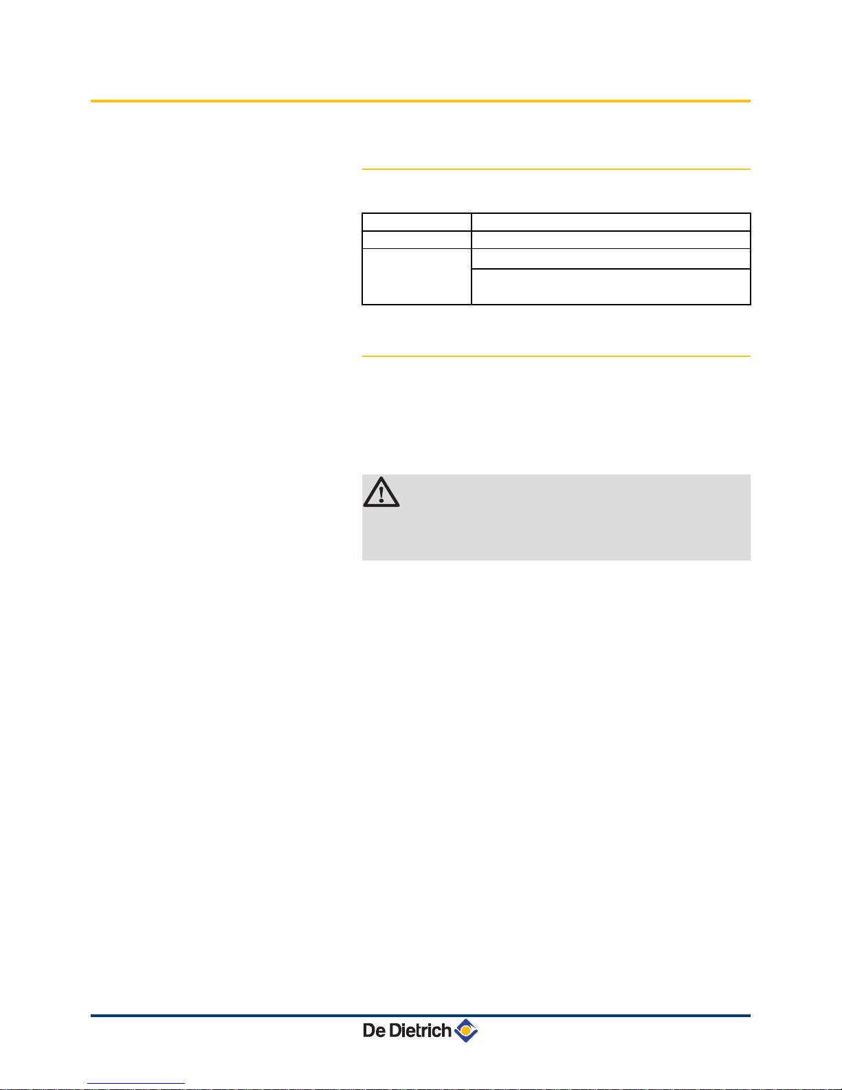
1.4.1. Certifications
CE identification no
PIN 0063CM3019
NOx classification
5 (Standards EN)
Type of connection Chimney: B23, B
23P
, B
33
Flue gas outlet: C
13(x)
, C
33(x)
, C
43(x)
, C53, C
63(x)
,
C
83(x)
, C
93(x)
1.4.2. Additional Directives
Apart from the legal provisions and Directives, the additional
Directives described in these instructions must also be observed
.
For all provisions and Directives referred to in these instructions, it is
agreed that all addenda or subsequent provisions will apply at the
time of installation.
WARNING
Installation of the appliance must be done by a qualified
engineer in accordance with prevailing local and national
regulations
.
1. Introduction EMC-M 24 EMC-M 24/28 MI EMC-M 30/35 MI EMC-M 34/39 MI
8
210212 - 7601972-03
2 Safety instructions and
recommendations
2.1 Safety instructions
DANGER
If you smell gas:
1.
Do not use a naked flame, do not smoke, do not
operate electrical contacts or switches ( doorbell,
light, motor, lift, etc..).
2. Shut off the gas supply.
3. Open the windows.
4. Trace possible leaks and seal them immediately.
5. If the gas leak is before the gas meter, contact the
gas supplier.
DANGER
If you smell flue gases:
1.
Switch the appliance off.
2. Open the windows.
3. Trace possible leaks and seal them immediately.
2.2 Recommendations
WARNING
4 Installation and maintenance of the boiler must be
carried out by a qualified professional in compliance
with prevailing local and national regulations.
4 When working on the boiler, always disconnect the
boiler from the mains and close the main gas inlet
valve.
4 After maintenance or repair work, check all
installations to ensure that there are no leaks.
CAUTION
The boiler must be installed in a frost-free environment.
Keep this document close to the place where the boiler is
installed.
Casing components
EMC-M 24 EMC-M 24/28 MI EMC-M 30/35 MI EMC-M 34/39 MI 2. Safety instructions and recommendations
210212 - 7601972-03
9

Only remove the casing for maintenance and repair operations. Put
the casing back in place after maintenance and repair operations.
Instructions stickers
The
instructions and warnings affixed to the appliance must never be
removed or covered and must remain legible during the entire lifespan
of the appliance. Immediately replace damaged or illegible
instructions and warning stickers.
Modifications
Modifications may only be made to the boiler after the written
permission of De Dietrich Thermique to do so.
2. Safety instructions and recommendations EMC-M 24 EMC-M 24/28 MI EMC-M 30/35 MI EMC-M 34/39 MI
10
210212 - 7601972-03
3 Technical description
3.1 General description
Wall-hung gas condensing boilers
4 High efficiency heating.
4 Low pollutant emissions.
4 Installation and connection facilitated by the mounting frame
delivered with the appliance.
4 Flue gas discharge via a forced flue, chimney, bi-flow or 3CE type
connection.
4 EMC-M 24: Heating only (Possibility of producing domestic hot
water via an independent tank which has been installed
separately).
4 EMC-M 24/28 MI - 30/35 MI - 34/39 MI: Heating and domestic hot
water production.
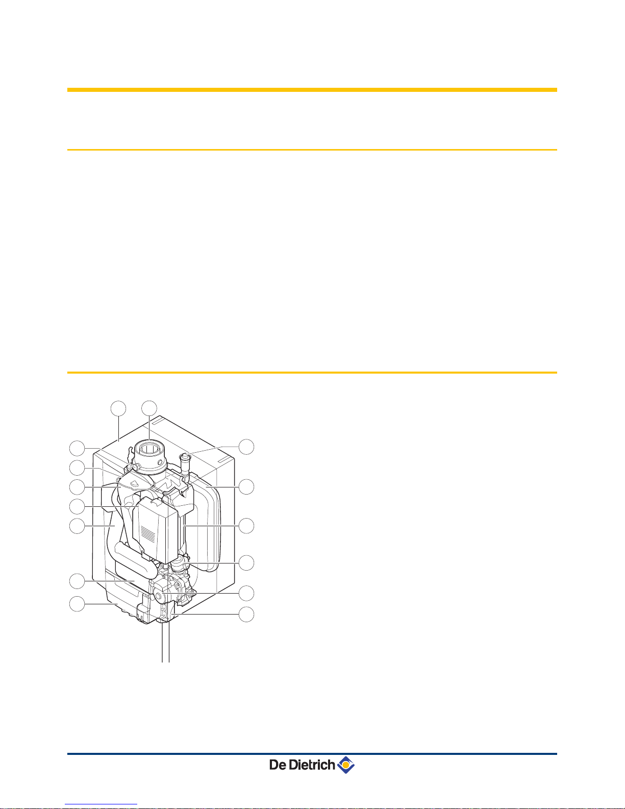
3.2 Main parts
1
Flue gas outlet/Air intake
2
Casing/air box
3
Outlet for measuring combustion gases
4
Ignition/ionization electrode
5
Flue gas discharge pipe
6
Gas/air system with a fan, gas block and automatic burner
unit
7
Air intake silencer
8
Plate heat exchanger (DHW) (Only on models with
domestic hot water production
)
9
Connection box
10
Siphon
11
Shunt pump
12
3-way valve
13
Heat exchanger (Central heating)
14
Expansion vessel
15
Automatic air vent
T004783-A
3
5
6
7
9
8
13
12
14
15
11
10
1
2
4
EMC-M 24 EMC-M 24/28 MI EMC-M 30/35 MI EMC-M 34/39 MI 3. Technical description
210212 - 7601972-03
11

3.3 Skeleton Diagrams
EMC-M 24
1
Heat exchanger (Central heating)
2
Safety valve
3
Heating flow (Primary circuit)
4
Heating flow (Secondary circuit)
5
Heating return (Secondary circuit)
6
Heating return (Primary circuit)
7
3-way valve
8
Shunt pump (Central heating)
EMC-M 24/28 MI - 30/35 MI - 34/39 MI
1
Heat exchanger (Central heating)
2
Hydroblock
3
Plate heat exchanger (DHW)
4
Safety valve
5
Heating flow
6
Domestic hot water outlet (DHW)
7
Domestic cold water inlet
8
Heating return
9
Shunt pump (Central heating)
10
3-way valve
3.4 Operating principle
3.4.1. Regulation of the water temperature
The boiler is fitted with an electronic temperature regulator having an
outlet
and return temperature probe. The flow temperature can be set
between 20°C and 90°C. The boiler reduces its power when the set
outlet-temperature is attained. The cutout temperature is the set
heating outlet-temperature + 5 °C.
T003806-A
3 4 5 6
1
2
8
7
T003393-D
5 6 7 8
1
2
3
4
10
9
3. Technical description EMC-M 24 EMC-M 24/28 MI EMC-M 30/35 MI EMC-M 34/39 MI
12
210212 - 7601972-03
3.4.2. Protection against a shortage of water
The boiler is fitted with a safety device to prevent the shortage of water
based on temperature measurements.
By reducing its output when
the water flow rate is in danger of becoming insufficient, the boiler
continues to operate as long as possible. In case of insufficient ΔT
≥ 50°C flow or an excessive increase in flow temperature, the boiler
will enter shutdown mode for 10 minutes. When there is no water in
the boiler, or if the pump is not running, the system is locked
(breakdown)
In the event of a fault, the status signal for the B
button on
the connection box flashes red.
¼For more detailed information, see chapter:
"Shutdowns and
lock-outs", page 60.
3.4.3. Maximum temperature protection
The maximum temperature protection locks the boiler if the water
temperature becomes too high (
110°C).
In the event of a fault, the status signal for the B
button on
the connection box flashes red.
¼For more detailed information, see chapter:
"Shutdowns and
lock-outs", page 60.
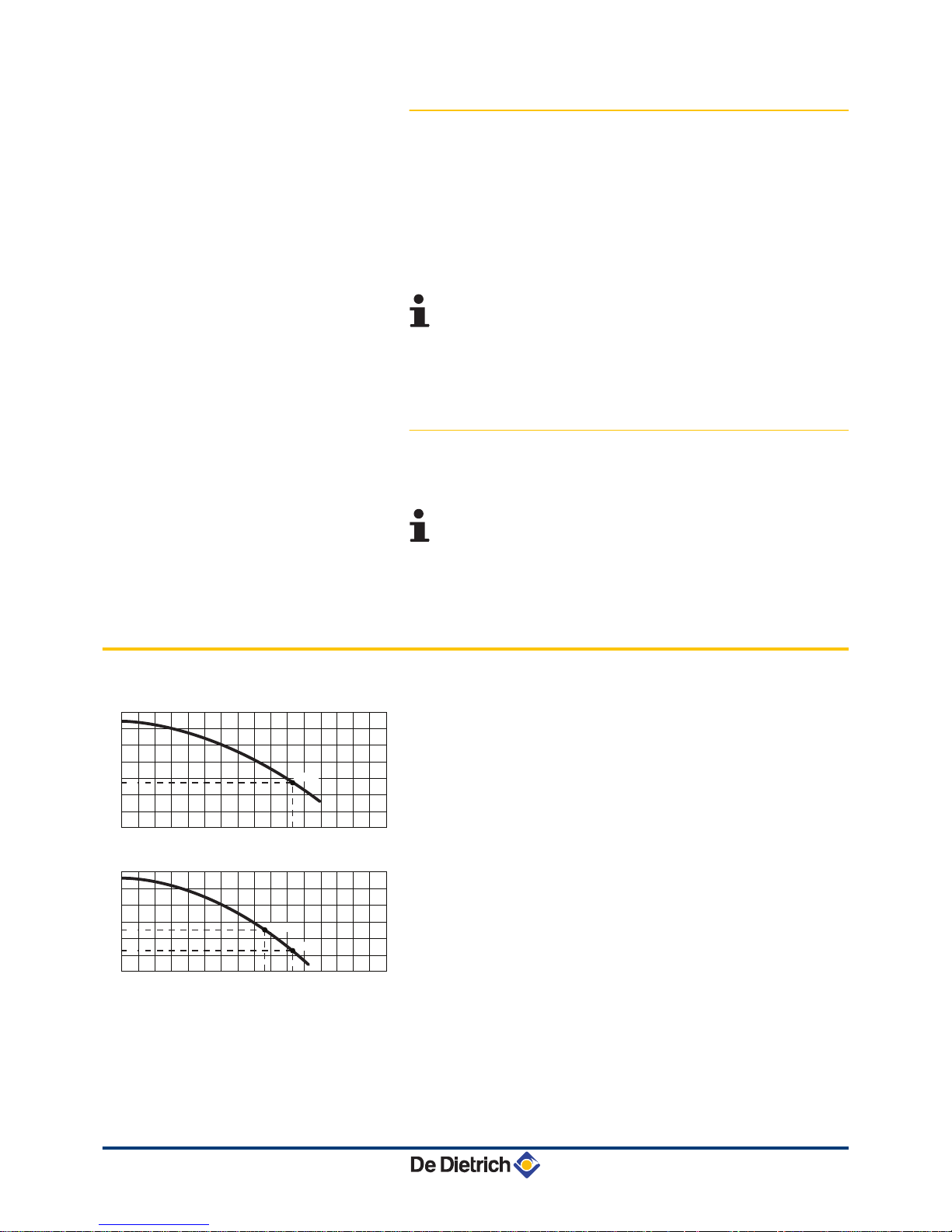
3.5 Circulating pump
The boiler is fitted with an on/off circulation pump.
EMC-M 24
H
Manometric height central heating circuit
Q
Water flow ( ΔT=20K)
EMC-M 24/28 MI
H
Manometric height central heating circuit
Q
Water flow ( ΔT=20K)
R000367-A
12001000600 800400200
0
0
100
200
300
400
500
600
Q (l/h)
16001400
700
H (mbar)
1030
24 kW
275
R000365-A
12001000600 800400200
0
0
100
200
300
400
500
600
H (mbar)
Q (l/h)
16001400
860
1030
20 kW
24 kW
253
127
EMC-M 24 EMC-M 24/28 MI EMC-M 30/35 MI EMC-M 34/39 MI 3. Technical description
210212 - 7601972-03
13

EMC-M 30/35 MI - 34/39 MI
H
Manometric height central heating circuit
Q
Water flow ( ΔT=20K)
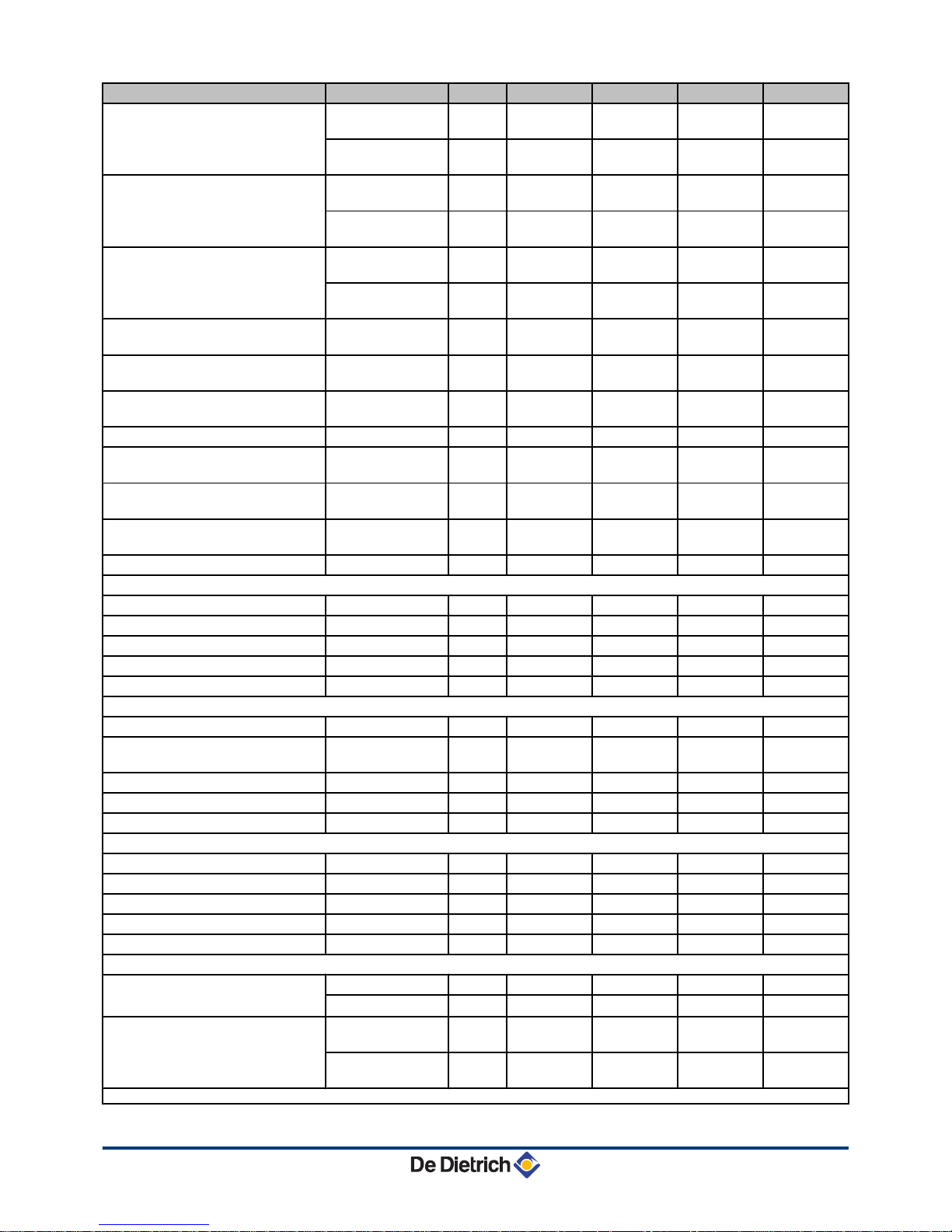
3.6 Technical specifications
Boiler type EMC- M
24 24/28 MI 30/35 MI 34/39 MI
General
EC indentification no. PIN
0063CM3019
Flow rate setting Adjustable
Modulating, Start/Stop
Nominal output (Pn)
Heating System (80/60 °C)
minimummaximum
kW 5,5 - 23,4 5,5 - 23,4 7,7 - 29,2 7,7 - 33,8
Factory setting kW 23,4 19,5 29,2 29,1
Nominal output (Pn)
Heating System (50/30 °C)
minimummaximum
kW 6,1 - 24,8 6,1 - 24,8 8,5 - 31,0 8,5 - 35,7
Factory setting kW 24,8 20,7 31,0 30,7
Nominal output (Pn)
DHW System
minimum maximum
kW - 5,5 - 27,5 7,7 - 33,9 7,7 - 37,8
Factory setting kW - 27,5 33,9 37,8
Nominal input (Qn)
Heating System (Hi)
minimum maximum
kW 5,6 - 24,0 5,6 - 24,0 7,8 - 30,0 7,8 - 34,9
Factory setting kW 24,0 20,0 30,0 30,0
Nominal input (Qn)
Heating System (Hs)
minimum maximum
kW 6,2 - 26,7 6,2 - 26,7
8,7 - 33,3 8,7 - 38,8
Factory setting kW 26,7 22,2 33,3 33,3
Nominal input (Qnw)
DHW System (Hi)
minimummaximum
kW -
5,6 - 28,2 7,8 - 34,9 7,8 - 39
Nominal input (Qnw)
DHW System (Hs)
minimummaximum
kW -
6,2 - 31,3 8,7 - 38,8 8,7 - 43,3
Nominal input (Qn)
Propane (Hi)
minimum kW
7,1 7,1 10 10
Nominal input (Qn)
Propane (Hs)
minimum kW
7,7 7,7 10,9 10,9
Heating efficiency under full load
(Hi) (80/60 °C)
- % 97,6 97,6 97,2 96,9
Heating efficiency under full load
(Hi) (50/30 °C)
- % 103,3 103,3 103,3 102,4
Heating efficiency under partial load
(Hi) (Return temperature 60
°C)
- % 97,8 97,8 98,4 98,4
Heating efficiency under partial load
(Hi) (92/42 EEG)
(Return temperature 30
°C)
- % 109,2 109,2 108,8 108,8
Data on the gases and combustion gases
Equipment categories
- II
2ESi3P
Type of air/flue gas connection
B23, B
23P
, B33, C
13x
, C
33x
, C
43x
, C53, C
63x
, C
83x
, C
93x
(1) Front panel removed
R000368-A
12001000600 800400200
0
0
100
200
300
400
500
600
Q (l/h)
16001400
700
H (mbar)
1250
30 kW
317
187
1500
35 kW
3. Technical description EMC-M 24 EMC-M 24/28 MI EMC-M 30/35 MI EMC-M 34/39 MI
14
210212 - 7601972-03
Boiler type EMC- M
24 24/28 MI 30/35 MI 34/39 MI
Gas inlet pressure G20 (Gas H) minimum-
maximum
mbar 17 - 30 17 - 30 17 - 30 17 - 30
Connecting
pressure
mbar 20 20 20 20
Gas inlet pressure G25 (Gas L) minimum-
maximum
mbar 20 - 30 20 - 30 20 - 30 20 - 30
Connecting
pressure
mbar 25 25 25 25
Gas inlet pressure G31 (Propane) minimum-
maximum
mbar 30- 50 30- 50 30- 50 30- 50
Connecting
pressure
mbar 37 37 37 37
Gas consumption G20 (Gas H) minimum-
maximum
m3/h
0,59 - 2,54 0,59 - 2,98 0,83 - 3,68 0,83 - 4,13
Gas consumption G25 (Gas L) minimum-
maximum
m3/h
0,69 - 2,95 0,69 - 3,47 0,96 - 4,28 0,96 - 4,80
Gas consumption G31 (Propane) minimum-
maximum
m3/h
0,29 - 0,98 0,29 - 1,15 0,41 - 1,42 0,41 - 1,47
NOx annual emission (n=1)
mg/kWh 58 58 52 56
NOx classification (EN 297 pr A3, EN
483)
5 5 5 5
Mass flue gas flow rate minimum-
maximum
kg/h
9,4 - 38,7 9,4 - 45,5 13,1 - 56,2 13,1 - 62,9
Flue gas temperature minimum-
maximum
°C
32 - 78 32 - 84 31 - 82 31 - 86
Maximum counter pressure
Pa 80 116 105 120
Characteristics of the heating circuit
Water content
l 1,4 1,6 1,7 1,7
Water operating pressure minimum bar 0,8 0,8 0,8 0,8
Water operating pressure (PMS) maximum bar 3,0 3,0 3,0 3,0
Water temperature maximum °C 110 110 110 110
Operating temperature maximum °C 90 90 90 90
Characteristics of the domestic hot water circuit
Specific hot water flow (∆T = 30K)
l/min - 14 17 19
Domestic water resistance (without
flow restrictor)
mbar - 123 215 260
Flow rate threshold minimum l/min - 1,2 1,2 1,2
Water content
l - 0,16 0,18 0,18
Operating pressure (Pmw) maximum bar - 8 8 8
Electrical characteristics
Power supply voltage
VAC 230 230 230 230
Power consumption Full load maximum W 117 117 145 159
Power consumption Part load maximum W 96 82 101 101
Power consumption - Standby maximum W 3 3 3 3
Electrical protection index
IP X4D X4D X4D X4D
Other characteristics
Weight (empty)
Total kg 24,5 26 28,5 28,5
Mounting
(1)
kg 23 24 27 27
Acoustic level at 1 metre
maximum Heating
System
dB(A) 40 38 42 42
maximum DHW
System
dB(A) _ 42 45 46
(1) Front panel removed
EMC-M 24 EMC-M 24/28 MI EMC-M 30/35 MI EMC-M 34/39 MI 3. Technical description
210212 - 7601972-03
15
4 Installation
4.1 Regulations governing installation
WARNING
Installation of the appliance must be done by a qualified
engineer in accordance with prevailing local and national
regulations.
4.2 Choice of the location
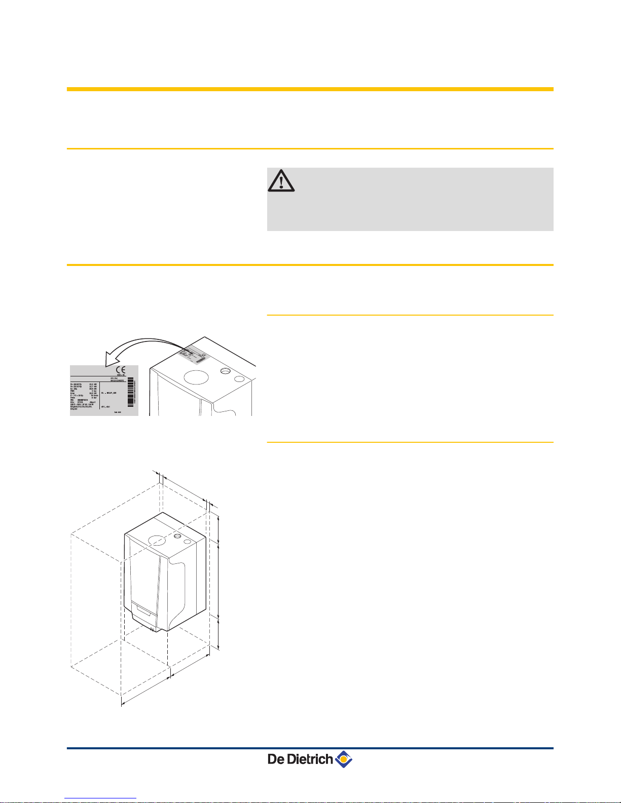
4.2.1. Data plate
The identification plate on top of the boiler features the boiler serial
number and important boiler specifications, for example the model
and unit category. The dF and dU codes are also stated on the type
plate.
4.2.2.
Location of the boiler
4 Before mounting the boiler, decide on the ideal position for
mounting, bearing the Directives and the dimensions of the
appliance in mind.
4 When choosing the position for mounting the boiler, bear in mind
the authorised position of the combustion gas discharge outlets
and the air intake opening.
4 Make sure there is enough room underneath the boiler for the
connection box.
4 To ensure adequate accessibility to the appliance and facilitate
maintenance, leave enough space around the boiler.
4 Mount the boiler onto a flat surface.
R000292-A
R000424-A
368
5
1000
364
≥ 200
5
≥ 250
554
4. Installation EMC-M 24 EMC-M 24/28 MI EMC-M 30/35 MI EMC-M 34/39 MI
16
210212 - 7601972-03
WARNING
4 Fix the appliance to a solid wall capable of bearing
the weight of the appliance when full of water and fully
equipped.
4 Do not place the appliance above a heat source or a
cooking appliance.
4 Do not locate the boiler in direct or indirect sunlight.
4 It is forbidden to store inflammable products and
materials in the boiler room or close to the boiler,
even temporarily.
CAUTION
4 The boiler must be installed in a frost-free
environment.
4 An earthed electrical connection must be available
close to the boiler.
4 A connection to the mains drainage system for the
discharge of condensate must be available close to
the boiler.
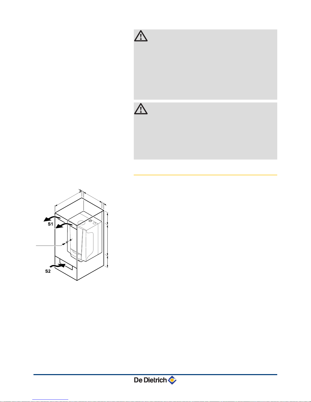
4.2.3. Ventilation
(1)
Distance between the front of the boiler and the internal
wall of the casing box.
If the boiler is installed in a closed casing, respect the minimum
dimensions given in the diagram opposite.
Also allow openings to
obviate the following hazards:
4 Accumulation of gas
4 Heating of the box
Minimum cross section of the openings: S1 + S2 = 150 cm
2
R000421-A
368
5
5
≥ 250
≥ 250
554
≥ 464
≥
100
(1)
EMC-M 24 EMC-M 24/28 MI EMC-M 30/35 MI EMC-M 34/39 MI 4. Installation
210212 - 7601972-03
17

4.3 Main dimensions
i
Connection of the combustion gas exhaust pipe; Ø 60 mm
h
Connection of the air intake pipe; Ø 100 mm
ê
Safety valve outlet pipe; Ø 15 mm
j
Condensates discharge; Ø 25 mm
{
Heating circuit flow; G¾"
y
Domestic hot water outlet; G½"
Gas /
Gaz
Gas connection; G½"
x
Domestic cold water inlet; G½"
z
Heating circuit return; G¾"
R000354-A
368
184
364
243
541
209
230
664
151
35
52
1
2
3
4
1
= 117
2
= 184
3
= 251
4
= 316
46
90
187
76
4. Installation EMC-M 24 EMC-M 24/28 MI EMC-M 30/35 MI EMC-M 34/39 MI
18
210212 - 7601972-03
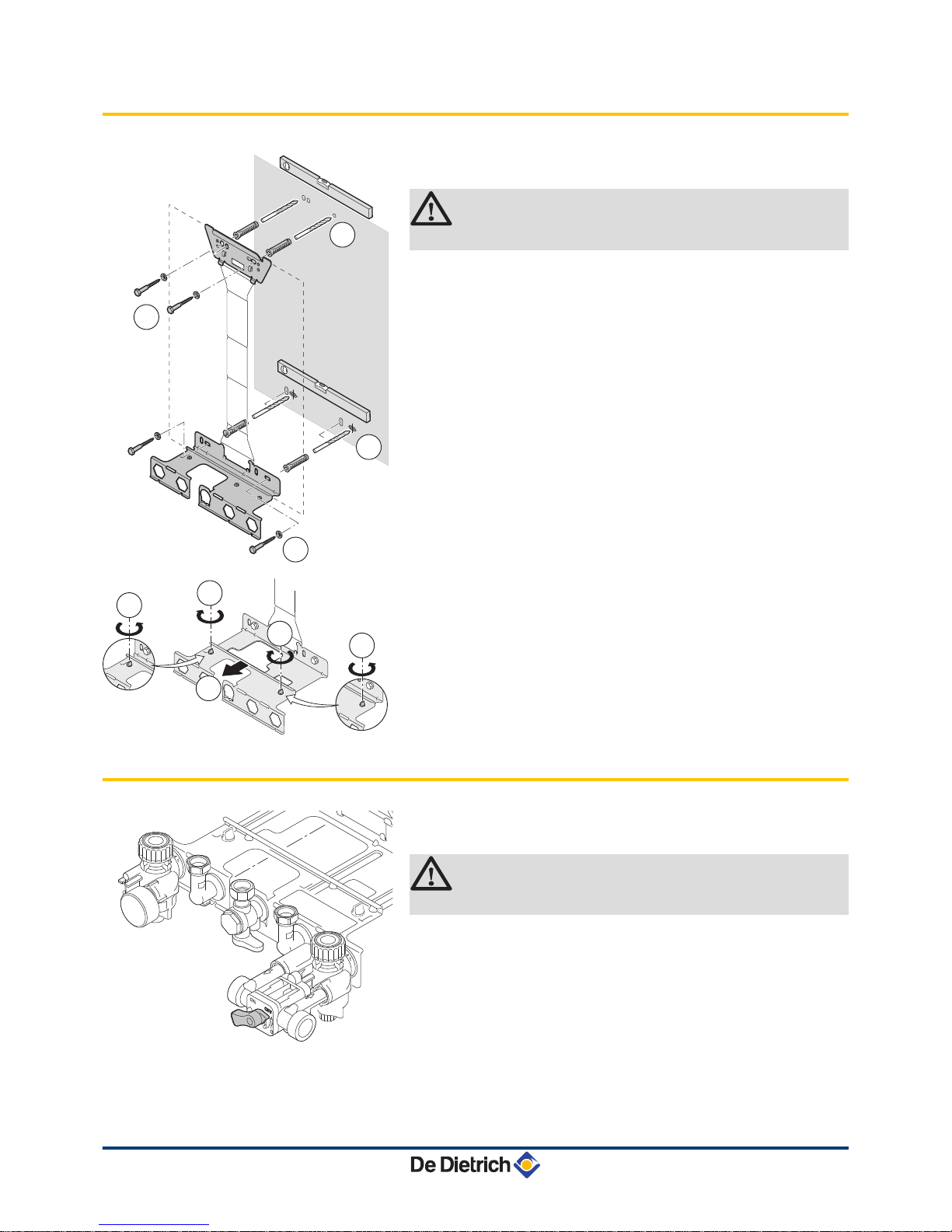
4.4 Installing the mounting frame
1. Drill 2 holes with Ø 10 mm for the lower part of the mounting
frame. Put the plugs in place.
CAUTION
Make sure that all the drill holes are level.
2. Affix
the lower part of the mounting frame to the wall using 2 of the
screws supplied.
3. Open out the mounting frame and mark out the 2 drill holes for the
upper part of the mounting frame on the wall. Drill 2 holes with a
Ø of 10 mm. Put the plugs in place.
4. Affix the upper part of the mounting frame to the wall using 2 of
the screws supplied.
5. Extend the mounting frame to its maximum depth to install a boiler
with a built-in expansion vessel. To do so, remove the plastic
screws from the lower bracket, and once it has been extended,
replace the screws to fix the mounting frame.
4.5 Positioning the boiler
1. Remove the protective caps from all of the hydraulic inlets and
outlets on the boiler.
CAUTION
The cock from the filling loop must be closed.
2. Fit a fibre gasket to each joint on the valve plate.
T003395-F
1
2
3
4
R000419-A
3
2
3
1
1
T002375-D
EMC-M 24 EMC-M 24/28 MI EMC-M 30/35 MI EMC-M 34/39 MI 4. Installation
210212 - 7601972-03
19
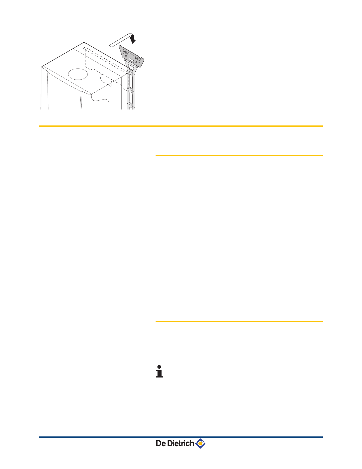
3. Position the boiler above the plumbing fixtures plate and locate it
against the mounting frame. Gently lower the boiler.
Mount the
boiler using the suspension bracket on the back of the boiler.
4. Tighten the valve nuts on the boiler.
4.6 Hydraulic connections
4.6.1. Flushing the system
Installation must be carried out in accordance with the prevailing
regulations,
the codes of practice and the recommendations in these
instructions.
Installing the boiler in new installations (installations less than
6 months old)
4 Clean the installation with a universal cleaner to eliminate debris
from the appliance (copper, hemp, flux).
4 Thoroughly flush the installation until the water runs clear and
shows no impurities.
Installing the boiler in existing installations
4 Remove sludge from the installation.
4 Flush the installation.
4 Clean the installation with a universal cleaner to eliminate debris
from the appliance (copper, hemp, flux).
4 Thoroughly flush the installation until the water runs clear and
shows no impurities.
4.6.2. Water flow rate
The boiler’s modulating control system limits the maximum difference
in
temperature between the heating flow and return and the maximum
speed at which the flow temperature increases. In this way, the boiler
does not require a minimum water flow rate.
If using a heating and domestic hot water production type
boiler on an installation in which the flow can be fully
disconnected from the return (e.g. by using thermostatic
valves), you should either fit a bypass or fit an expansion
vessel to the heating flow conduit.
R000420-A
4. Installation EMC-M 24 EMC-M 24/28 MI EMC-M 30/35 MI EMC-M 34/39 MI
20
210212 - 7601972-03
4.6.3. Connection of the heating circuit
1. Connect the heating water return pipe to the heating return
connection z.
2.
Connect the heating water outlet pipe to the heating flow
connection {.
CAUTION
4 The heating pipe must be mounted in accordance
with prevailing provisions.
4 Carry out any welding work required at a safe
distance from the boiler or before the boiler is fitted
.
4 Install a drain under the safety valve leading to the
sewage system ê.
4.6.4. Connection of the water circuit for
domestic use
1. Connect the cold water inlet pipe to the domestic cold water
connection k.
2.
Connect the domestic hot water outlet pipe to the domestic hot
water connection m.
CAUTION
4 The domestic water pipes must be connected in
accordance with prevailing provisions.
4 Carry out any welding work required at a safe
distance from the boiler or before the boiler is fitted
.
4 If using synthetic pipes, follow the manufacturer’s
(connection) instructions.
4.6.5. Connecting the expansion vessel
The boiler is fitted as standard with an 8-litre expansion vessel.
If
the water volume is greater than 100 litres or the static height of the
system exceeds 5 metres, an additional expansion vessel must be
fitted. Refer to the table below to determine the expansion vessel
required for the installation.
Conditions of validity of the table:
4 3-bar safety valve
4 Average water temperature: 70 °C
Flow temperature: 80 °C
Return temperature: 60 °C
4 The filling pressure in the system is lower than or equal to the initial
pressure in the expansion vessel
EMC-M 24 EMC-M 24/28 MI EMC-M 30/35 MI EMC-M 34/39 MI 4. Installation
210212 - 7601972-03
21
Initial pressure of the
expansion vessel
Volume of the expansion vessel depending on the volume of the installation (in litres)
100 125 150 175 200 250 300 > 300
0.5 bar 4,8 6,0 7,2 8,4 9,6 12,0 14,4 Volume of the installation x 0,048
1 bar
8,0
(1)
10,0 12,0 14,0 16,0 20,0 24,0 Volume of the installation x 0,080
1.5 bar 13,3 16,6 20,0 23,3 26,6 33,3 39,9 Volume of the installationx 0,133
(1) Factory configuration
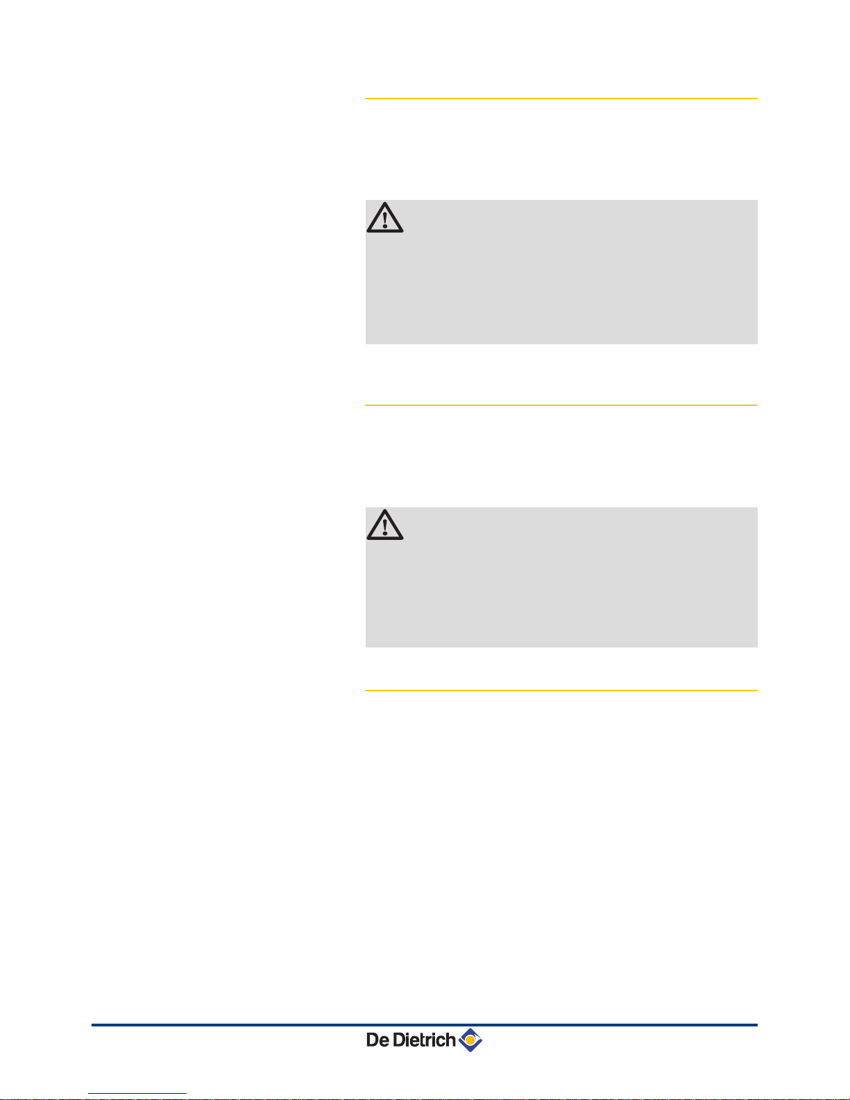
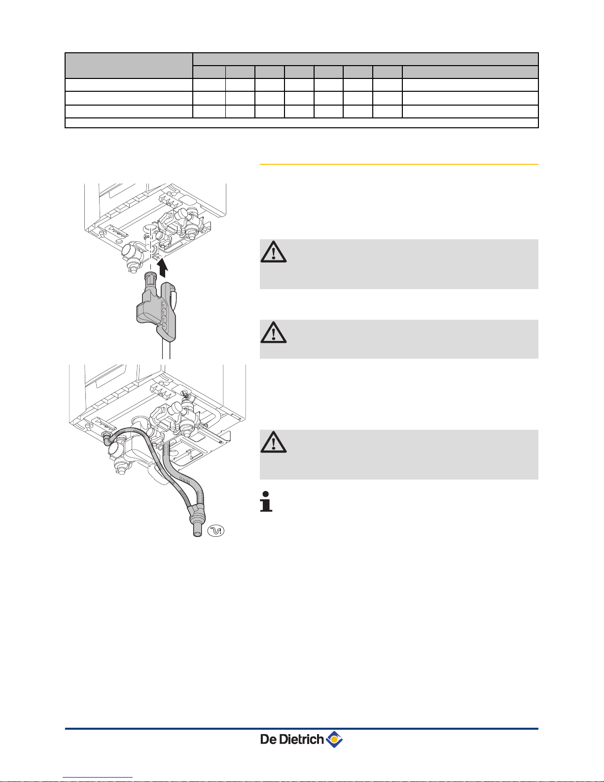
4.6.6. Connecting
the condensate discharge pipe
The syphon is supplied separately as standard with the boiler
(Includes flexible plastic drain hose
). Fit these parts underneath the
boiler. To do this, proceed as follows:
1. Fill the syphon with water up to the mark.
CAUTION
Fill the water siphon before starting the boiler to avoid
combustion products escaping from the boiler.
2.
Press the syphon firmly into the j opening provided for it
underneath the boiler.
The syphon must click into place.
CAUTION
Check whether the syphon is solidly fitted in the boiler.
3. Mount
a standard drainage pipe, Ø 32 mm or more, leading to the
mains drainage system.
4. Mount the flow collector.
5.
Insert the hoses from the siphon drain j and safety valve ê.
6. Mount a trap or a siphon in the discharge pipe.
CAUTION
Do not make a fixed connection owing to maintenance
work on the siphon.
4 Do
not plug the condensate discharge pipe. Make an
open connection with the drain.
4 Set the discharge pipe at a gradient of at least 30 mm
per metre, maximum horizontal length 5 metres.
4 Do not drain condensation water into a roof gutter at
any time.
4 Connect the condensate discharge pipe in
accordance with prevailing standards.
T004860-B
T004868-D
4. Installation EMC-M 24 EMC-M 24/28 MI EMC-M 30/35 MI EMC-M 34/39 MI
22
210212 - 7601972-03
 Loading...