

DeDietrich Elitec DTG 1304 Eco.NOx/V, Elitec DTG 1305 Eco.NOx/V, Elitec DTG 1306 Eco.NOx/V Technical Instructions
Page 1
Elitec
DTG 1300 Eco.NOx/V
Gas-fired boilers
English
23/06/05
Technical
instructions
Page 2

Contents
Compliance. . . . . . . . . . . . . . . . . . . . . . . . . . . . . . . . . . . . . . . . . . . . . . . . . . . . . . . . . . . . . . . . . . . . . . . . . . . . . . . . . .3
Introduction . . . . . . . . . . . . . . . . . . . . . . . . . . . . . . . . . . . . . . . . . . . . . . . . . . . . . . . . . . . . . . . . . . . . . . . . . . . . . . . . .4
1 Important recommendations. . . . . . . . . . . . . . . . . . . . . . . . . . . . . . . . . . . . . . . . . . . . . . . . . . . . . . . . . . . . . . . . . . . . . . . . . . . . . . . . . .4
2 Regulations . . . . . . . . . . . . . . . . . . . . . . . . . . . . . . . . . . . . . . . . . . . . . . . . . . . . . . . . . . . . . . . . . . . . . . . . . . . . . . . . . . . . . . . . . . . . . .4
3 Symbols used. . . . . . . . . . . . . . . . . . . . . . . . . . . . . . . . . . . . . . . . . . . . . . . . . . . . . . . . . . . . . . . . . . . . . . . . . . . . . . . . . . . . . . . . . . . . .5
Description . . . . . . . . . . . . . . . . . . . . . . . . . . . . . . . . . . . . . . . . . . . . . . . . . . . . . . . . . . . . . . . . . . . . . . . . . . . . . . . . . .6
1 Introduction. . . . . . . . . . . . . . . . . . . . . . . . . . . . . . . . . . . . . . . . . . . . . . . . . . . . . . . . . . . . . . . . . . . . . . . . . . . . . . . . . . . . . . . . . . . . . . .6
2 Composition of the range. . . . . . . . . . . . . . . . . . . . . . . . . . . . . . . . . . . . . . . . . . . . . . . . . . . . . . . . . . . . . . . . . . . . . . . . . . . . . . . . . . . .6
3 Certifications. . . . . . . . . . . . . . . . . . . . . . . . . . . . . . . . . . . . . . . . . . . . . . . . . . . . . . . . . . . . . . . . . . . . . . . . . . . . . . . . . . . . . . . . . . . . . .6
4 Main parts. . . . . . . . . . . . . . . . . . . . . . . . . . . . . . . . . . . . . . . . . . . . . . . . . . . . . . . . . . . . . . . . . . . . . . . . . . . . . . . . . . . . . . . . . . . . . . . .7
5 Technical characteristics . . . . . . . . . . . . . . . . . . . . . . . . . . . . . . . . . . . . . . . . . . . . . . . . . . . . . . . . . . . . . . . . . . . . . . . . . . . . . . . . . . . .8
6 Main dimensions . . . . . . . . . . . . . . . . . . . . . . . . . . . . . . . . . . . . . . . . . . . . . . . . . . . . . . . . . . . . . . . . . . . . . . . . . . . . . . . . . . . . . . . . . .9
7 Package list . . . . . . . . . . . . . . . . . . . . . . . . . . . . . . . . . . . . . . . . . . . . . . . . . . . . . . . . . . . . . . . . . . . . . . . . . . . . . . . . . . . . . . . . . . . . . .9
Installation . . . . . . . . . . . . . . . . . . . . . . . . . . . . . . . . . . . . . . . . . . . . . . . . . . . . . . . . . . . . . . . . . . . . . . . . . . . . . . . . .10
1 Implementation. . . . . . . . . . . . . . . . . . . . . . . . . . . . . . . . . . . . . . . . . . . . . . . . . . . . . . . . . . . . . . . . . . . . . . . . . . . . . . . . . . . . . . . . . . .10
2 Levelling. . . . . . . . . . . . . . . . . . . . . . . . . . . . . . . . . . . . . . . . . . . . . . . . . . . . . . . . . . . . . . . . . . . . . . . . . . . . . . . . . . . . . . . . . . . . . . . .11
Control panel assembly . . . . . . . . . . . . . . . . . . . . . . . . . . . . . . . . . . . . . . . . . . . . . . . . . . . . . . . . . . . . . . . . . . . . . .12
Connecting the furnace. . . . . . . . . . . . . . . . . . . . . . . . . . . . . . . . . . . . . . . . . . . . . . . . . . . . . . . . . . . . . . . . . . . . . . .16
1 Hydraulic connections . . . . . . . . . . . . . . . . . . . . . . . . . . . . . . . . . . . . . . . . . . . . . . . . . . . . . . . . . . . . . . . . . . . . . . . . . . . . . . . . . . . . .16
2 Connecting the gas channel. . . . . . . . . . . . . . . . . . . . . . . . . . . . . . . . . . . . . . . . . . . . . . . . . . . . . . . . . . . . . . . . . . . . . . . . . . . . . . . . .16
3 Connecting to a chimneye . . . . . . . . . . . . . . . . . . . . . . . . . . . . . . . . . . . . . . . . . . . . . . . . . . . . . . . . . . . . . . . . . . . . . . . . . . . . . . . . . .17
4 Electrical connections. . . . . . . . . . . . . . . . . . . . . . . . . . . . . . . . . . . . . . . . . . . . . . . . . . . . . . . . . . . . . . . . . . . . . . . . . . . . . . . . . . . . . .17
Adapting to another gas . . . . . . . . . . . . . . . . . . . . . . . . . . . . . . . . . . . . . . . . . . . . . . . . . . . . . . . . . . . . . . . . . . . . . .18
1 Attaching the label . . . . . . . . . . . . . . . . . . . . . . . . . . . . . . . . . . . . . . . . . . . . . . . . . . . . . . . . . . . . . . . . . . . . . . . . . . . . . . . . . . . . . . . .18
2 Changing the burner injectors . . . . . . . . . . . . . . . . . . . . . . . . . . . . . . . . . . . . . . . . . . . . . . . . . . . . . . . . . . . . . . . . . . . . . . . . . . . . . . .18
3 Changing the ignition burner injector . . . . . . . . . . . . . . . . . . . . . . . . . . . . . . . . . . . . . . . . . . . . . . . . . . . . . . . . . . . . . . . . . . . . . . . . . .18
4 Setting the injector pressure. . . . . . . . . . . . . . . . . . . . . . . . . . . . . . . . . . . . . . . . . . . . . . . . . . . . . . . . . . . . . . . . . . . . . . . . . . . . . . . . .19
5 Pressure settings and calibrated injector markings . . . . . . . . . . . . . . . . . . . . . . . . . . . . . . . . . . . . . . . . . . . . . . . . . . . . . . . . . . . . . . .19
Commissionning . . . . . . . . . . . . . . . . . . . . . . . . . . . . . . . . . . . . . . . . . . . . . . . . . . . . . . . . . . . . . . . . . . . . . . . . . . . .20
1 Refilling the installation. . . . . . . . . . . . . . . . . . . . . . . . . . . . . . . . . . . . . . . . . . . . . . . . . . . . . . . . . . . . . . . . . . . . . . . . . . . . . . . . . . . . .20
2 Final checks before commissioning. . . . . . . . . . . . . . . . . . . . . . . . . . . . . . . . . . . . . . . . . . . . . . . . . . . . . . . . . . . . . . . . . . . . . . . . . . .20
3 Commissionning. . . . . . . . . . . . . . . . . . . . . . . . . . . . . . . . . . . . . . . . . . . . . . . . . . . . . . . . . . . . . . . . . . . . . . . . . . . . . . . . . . . . . . . . . .21
4 Furnace operation equipped with safety box 577 DBC . . . . . . . . . . . . . . . . . . . . . . . . . . . . . . . . . . . . . . . . . . . . . . . . . . . . . . . . . . . .21
5 Checks and adjustments after commissioning. . . . . . . . . . . . . . . . . . . . . . . . . . . . . . . . . . . . . . . . . . . . . . . . . . . . . . . . . . . . . . . . . . .22
Maintenance . . . . . . . . . . . . . . . . . . . . . . . . . . . . . . . . . . . . . . . . . . . . . . . . . . . . . . . . . . . . . . . . . . . . . . . . . . . . . . . .24
1 Cleaning main burner and ignition burner . . . . . . . . . . . . . . . . . . . . . . . . . . . . . . . . . . . . . . . . . . . . . . . . . . . . . . . . . . . . . . . . . . . . . .24
2 Cleaning heater body. . . . . . . . . . . . . . . . . . . . . . . . . . . . . . . . . . . . . . . . . . . . . . . . . . . . . . . . . . . . . . . . . . . . . . . . . . . . . . . . . . . . . .25
3 Maintenance. . . . . . . . . . . . . . . . . . . . . . . . . . . . . . . . . . . . . . . . . . . . . . . . . . . . . . . . . . . . . . . . . . . . . . . . . . . . . . . . . . . . . . . . . . . . . 2 5
Incidents and solutions. . . . . . . . . . . . . . . . . . . . . . . . . . . . . . . . . . . . . . . . . . . . . . . . . . . . . . . . . . . . . . . . . . . . . . .27
Spare parts . . . . . . . . . . . . . . . . . . . . . . . . . . . . . . . . . . . . . . . . . . . . . . . . . . . . . . . . . . . . . . . . . . . . . . . . . . . . . . . . .29
Warranty . . . . . . . . . . . . . . . . . . . . . . . . . . . . . . . . . . . . . . . . . . . . . . . . . . . . . . . . . . . . . . . . . . . . . . . . . . . . . . . . . . .35
DTG 1300 Eco.NOx/V 23/06/05 - 300002940-001B
Page 3

Declaration of compliance
1
Declaration of compliance A.R. 8/1/2004 - BE
Manufacturer DE DIETRICH THERMIQUE S.A.S.
57 rue de la gare
F-67580 MERTZWILLER
+33 3 88 80 27 00
*
+33 3 88 80 27 99
+
Issued by See end of notice
We hereby certify that the range of equipment specified below is in accordance with the format stated in the EC declaration of comformity,
that it is manufactured and distributed in accordance with the regulations and requirements in European Directives and with the regulations
and requirements defined in the Royal Decree dated 8th January 2004.:
Product type Floor-standing gas boiler DTG 1300 Eco.NOx/V
Formats 18, 24, 30 kW
Standard applied - Royal Decree dated 8th January 2004
- 90/396/EEC Gas Appliance Directive
Reference Standard : EN 297 ; EN 437
- 73/23/EEC Low Voltage Directive
Reference Standard : EN 60.335.1
- 89/336/EEC Electromagnetic Compatibility Directive
Reference Standard : EN 61000-6-3 ; EN 61000-6-1
- 92/42/EEC Efficiency Directive * *
Low temperature gas boiler
Inspecting organisation Gas Wärme Institut / DVGW PV N° 14846 (06/01/2004)
Measured values NOx: < 70 mg / kWh
CO: < 10 mg / kWh
Date: 22 juin 2004 Signature
Technical Director
Mr. Bertrand Schaff
1
23/06/05 - 300002940-001B DTG 1300 Eco.NOx/V
3
Page 4

1 Important recommendations
Introduction
For a proper operating of the boiler, follow carefully the
instructions.
Any intervention on the appliance and heating equipment
must be carried out by a qualified technician.
The manufacturer is not liable for any improper use of the
appliance or failure to maintain or install the unit correctly
(the user shall take care to ensure that the system is
installed by a qualified fitter).
2 Regulations
Certificate of compliance
For the application of article 25 of the modified decree dated 02/08/
1977 and of article 1 of the modifed decree dated 05/02/1999, the
installation engineer must be in possession of the certificates of
compliance approved by the Ministries in charge of construction and
gas safety:
- Different forms (forms 1, 2 or 3) for a new gas installation
- "Model 4" in particular after replacing a furnace with a new one
Residential buildings
Statutory terms and conditions of installation and maintenance:
The installation and maintenance of the appliance must be carried
out by a qualified professional in compliance with the statutory texts
of the codes of conduct in force, particularly:
- Order of 2 August 1977
Technical and safety rules applicable to combustible gas and
liquefied hydrocarbon installations situated inside residential
buildings and their annexes.
- NF P 45-204 standards
Gas installation, (formerly DTU 61-1, gas installations: April 1982,
addendum no 1: July 1984).
Check that the equipment is properly set for the type of gas
used.
Keep to the polarity shown on the terminals : phase (L),
neutral (N) and earth
Check the seal on the gas and water pipe connections.
Establishments open to the public
Statutory terms and conditions of installation:
The installation and maintenance of the appliance must be carried
out in compliance with the statutory texts and rules of the codes of
conduct in force, particularly:
- Safety regulations against fire and panic in establishments open to
the public:
a. General regulations
For all appliances:
- Articles GZ - Installations operating on combustible gases and
liquefied hydrocarbons.
Then, depending on use:
- Articles CH-Heating, ventilation, refrigeration, air conditioning and
production of steam and domestic hot water.
b. Instructions specific to each type of establishment open to the
public (hospitals, stores, etc.)
4
.
- Local Sanitary Regulations
For appliances connected to the electricity network:
- NF C 15-100 standards Low voltage electrical installation - Rules..
4
DTG 1300 Eco.NOx/V 23/06/05 - 300002940-001B
Page 5

3 Symbols used
Symbols used
Caution danger
Risk of injury and damage to equipment.
Attention must be paid to the warnings on safety
of persons and equipment.
Z
Specific information
Reference
Information must be kept in mind to maintain
comfort.
Refer to another manual or other pages in this
instruction manual.
23/06/05 - 300002940-001B DTG 1300 Eco.NOx/V
5
Page 6

1Introduction
Description
The ELITEC DTG 1300 Eco.NOx/V boiler is a floor-standing cast
iron gas-fired boiler with an atmospheric burner with very low
pollutant emission with integrated domestic hot water production.
The boiler must only be connected to a chimney.
The design of the cast iron heater body with interleaved spurs gives
very high performance. Also, the baffling in the smoke circuits limits
the natural chimney effect and gives high performance yields.
2 Composition of the range
Heating and domestic hot water
- DTG 1300 Eco.NOx/V or H Panel B:
Boiler with (110 ou 130 l) domestic hot water tank and electronic
command panel
- DTG 1300 Eco.NOx/V or H Panel E:
Boiler with (110 ou 130 l) domestic hot water tank and electronic
command panel with extractable or built-in Easymatic regulator
3 Certifications
3.1 Introduction
97/23/CE Directive
The boilers are equipped with an anti smoke release safety device ;
they may therefore be installed in inhabited areas. It consists of a
thermostat located in the anti-blowback which causes the burner to
stop for 15 minutes. This is indicated by an alarm light flashing on the
control panel. The boiler automatically restarts after 15 minutes if the
cause of the cut off has been removed.
The tightly packed insulation of the boiler equipment reduces losses
into the atmosphere to very low levels.
- DTG 1300 Eco.NOx/V or H Panel D:
Heater with (110 ou 130 l) domestic hot water tank and DIEMATIC
3 electronic command panel
The command panel gives priority to producing domestic hot
water.
Gas and oil boilers with a maximum operating temperature of 110°C
and hot water tanks with a maximum operating pressure of 10 bar
pertain to article 3.3 of the directive, and therefore, cannot be CEmarked to certify compliance with the directive 97/23 EC.
De Dietrich boilers and DHW tanks conform to the regulations in
article 3.3 of the 97/23/CEE Directive and is backed by the CE mark
for the 90/396/CEE, 92/42/CEE, 72/73 CEE and 89/336/CEE
directives.
CE identification no: CE-0085BP0002
Type B11
boiler
BS
The boilers leave the factory operating with H natural gas. To operate
with L Natural gas or with propane: see chapter "Adapting to another
gas"
France:
Thermal performance level (according to NFD 30-002): B300
Performance class III boiler according to ATG B 84
recommendations.
Switzerland:
Boilers are tested under the LRV-92 standard.
6
DTG 1300 Eco.NOx/V 23/06/05 - 300002940-001B
Page 7
3.2 User country
User country Gas category Gas type Connection pressure (mbar)
FR
ES, PT, IE, CH, GB, DK, CZ, GR
IT, SE, NO, FI, IS
AT
DE
NL
LU
HU
II
II
II
II
II
II
II
2ESi3P
2H3P
I
2H
2H3P
2ELL3P
2L3P
2E3P
2ES3P
G20 20
G25 25
G31 37
G20 20
G31 30/37
G20 20
G20 20
G31 50
G20 20
G25 20
G31 50
G25 25
G31 50
G20 20
G25 20
G31 50
G20 25
G25.1 25
G31 30/50
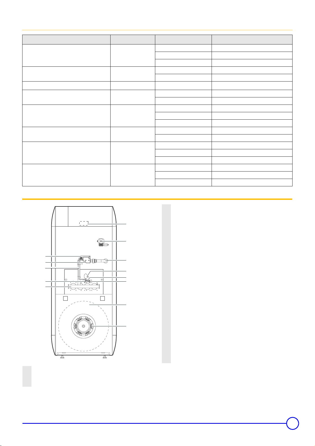
4Main parts
1
2
9
6
4
8518N070
10
11
3
5
8
7
18
19
Gas regulation block: It has a progressive opening,
2
regulation valve and safety valve in series which is controlled
by the boiler adjustment dial.
3
Gas inlet
4
Burner
5
Flame inspection window
Ignition electrode: This ensures ignition burner ignition using
6
a high voltage spark.
Ionisation probe: This detects the presence of a burner
7
ignition flame through ionisation.
8
Ignition burner
9
Ignition burner gas supply pipe
Anti-smoke release thermostat (located on the rear wall of
the anti-blowback device): In the event of smoke release, the
burner is cut and the boiler goes into standby for 15 minutes. It
10
must not be switched off or moved at any time.The boiler
restarts normally after this thermostat has cooled and the 15
minutes has finished (indicated by an alarm indicator flashing
on the command panel).
11
Sensor tube
18
Domestic hot water tank
19
Flange for the domestic hot water tank
Safety box: Mounted on the gas block to ensure and check
1
ignition sequences, plus burner operation and extinguishing
sequences.
23/06/05 - 300002940-001B DTG 1300 Eco.NOx/V
7
Page 8
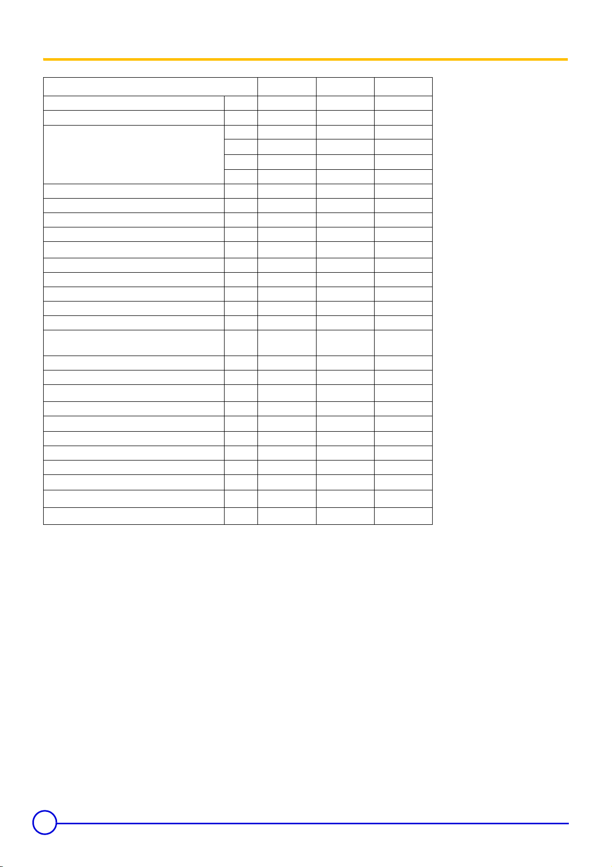
5 Technical characteristics
DTG ... Eco.NOx 1304 1305 1306
Nominal power Pn kW 12 18 24
Power input kW 13,4 20,1 26,7
Gas flow rate
- Natural gas H (G20)
- Natural gas L (G25)
- Propane (G31)
(1)
(1)
3
/h
m
3
/h
m
1,42 2,13 2,83
1,65 2,47 3,29
kg/h 1,04 1,56 2,07
Number of cast iron parts 3 4 5
Number of nozzles 2 3 4
Mass flue gas flow rate (G20) kg/h 48 53 70
Smoke temperature °C 100 120 125
Minimal ionisation current
(2)
µA 0,3 0,3 0,3
Required depressurisation at the nozzle mbar 0,05 0,05 0,05
Min water temperature °C 30 30 30
Max water temperature °C 90 90 90
Maximum admissible operating pressure bar 4 4 4
Electrical connection V-HZ 230-50 230-50 230-50
Absorbed electrical power
(Heating mode)
W121212
Gas connection inch R 1/2 R 1/2 R 1/2
Water connection inch R 1 R 1 R 1
Smoke connection (internal diameter) mm
110 / 111
(3)
110 / 111
(3)
125 / 130
Water capacity l 7,1 8,8 10,5
Loss of hydraulic circuit load at
∆T = 15 K
mbar 4 8 15
Net weight kg 87 100 118
Shipping weight kg 97 113 133
Tank storage capacity l 110 110 130
Hourly flow at
Specific flow à ∆T = 30 K selon EN 625
Flow in 10 minutes à
(1)
15°C / 1013 mbar
(2 )
In order to measure the ionisation current, take out the ionisation
∆T = 35 K
∆T = 30 K
(4) (6)
(4) (6)
l/h 440 590 690
l/min 19,0 19,0 22,0
l/min 190 190 220
cable connector and insert a micro-ammeter.
(3)
According to the national standard (possible adaptation of the two
diameters).
(4)
Domestic cold water à 10°C
(5)
Domestic hot water at 45°C
Primary input temperature at 80°C
(6)
Set DHW temperature chaudière à 80°C
Domestic hot water à 40°C
Tank load temperature at 60°C
1 mbar = 10 mmCE = 10 daPa = 100 Pa
(3)
8
DTG 1300 Eco.NOx/V 23/06/05 - 300002940-001B
Page 9
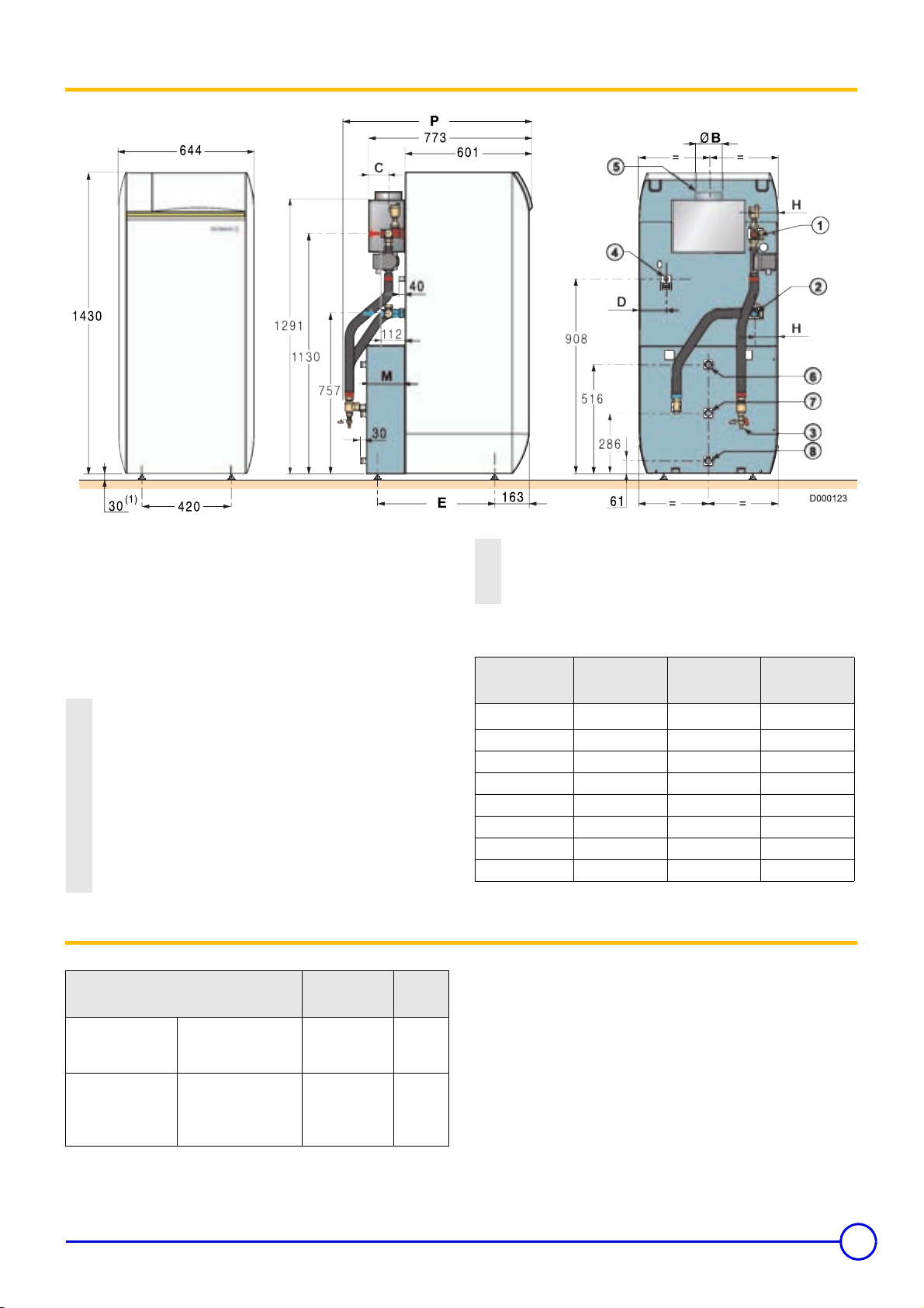
6 Main dimensions
(1)
Adjustable feet : basic sizes : 40 mm. Can be adjusted from 40 mm
to 55 mm. All height dimensions are given with a feet setting of 40
mm (see chapter Levelling).
(2)
According to the national standard (possible adaptation of the two
diameters)
R = Thread
G = Exterior cylinder thread, sealed by flat joint
Heating outlet
1
R 1 (1") for one single boiler
G1 (1") for boiler with DHW tank
Heating return
2
R 1 (1") for one single boiler
G1 (1") for boiler with DHW tank
Filling and emptying tap (connection for 14 mm interior diameter
3
pipe)
4 Gas inlet ø K
5 Smoke nozzle ø B
7 Package list
Pack
no.
GL 30
GL 11
GL 12
GL 25
GL 26
GL 35
GL 27
Boiler assembly
Control panel
Description Reference
DTG 1304 Eco.NOx/V
DTG 1305 Eco.NOx/V
DTG 1306 Eco.NOx/V
B (Base)
E (Easymatic)
ER (Easyradio)
D (Diematic 3)
8518-9024
8518-9025
8518-9026
8518-7000
8518-7001
100000473
8518-7002
6 Hot water outlet R 3/4 (3/4")
7 Circulation R 3/4 (3/4")
8 Cold water inlet R 3/4 (3/4")
IN ORDER TO FACILITATE BLEEDING, the installation must be
filled via the drainage/filling valve.
Formats DTG
...Eco.NOx/V
øB
C 100 93 85
D 156 120 84
E 550 550 635
H 143 107 71
øK (inch) R 1/2 R 1/2 R 1/2
M 182 182 267
P 878 878 1050
Refer to the applicable price list for any optional features used.
Z
1304 1305 1306
110 / 111
(2)
125 / 130
(2)
150 / 153
(2)
23/06/05 - 300002940-001B DTG 1300 Eco.NOx/V
9
Page 10
Installation
5
ht
w
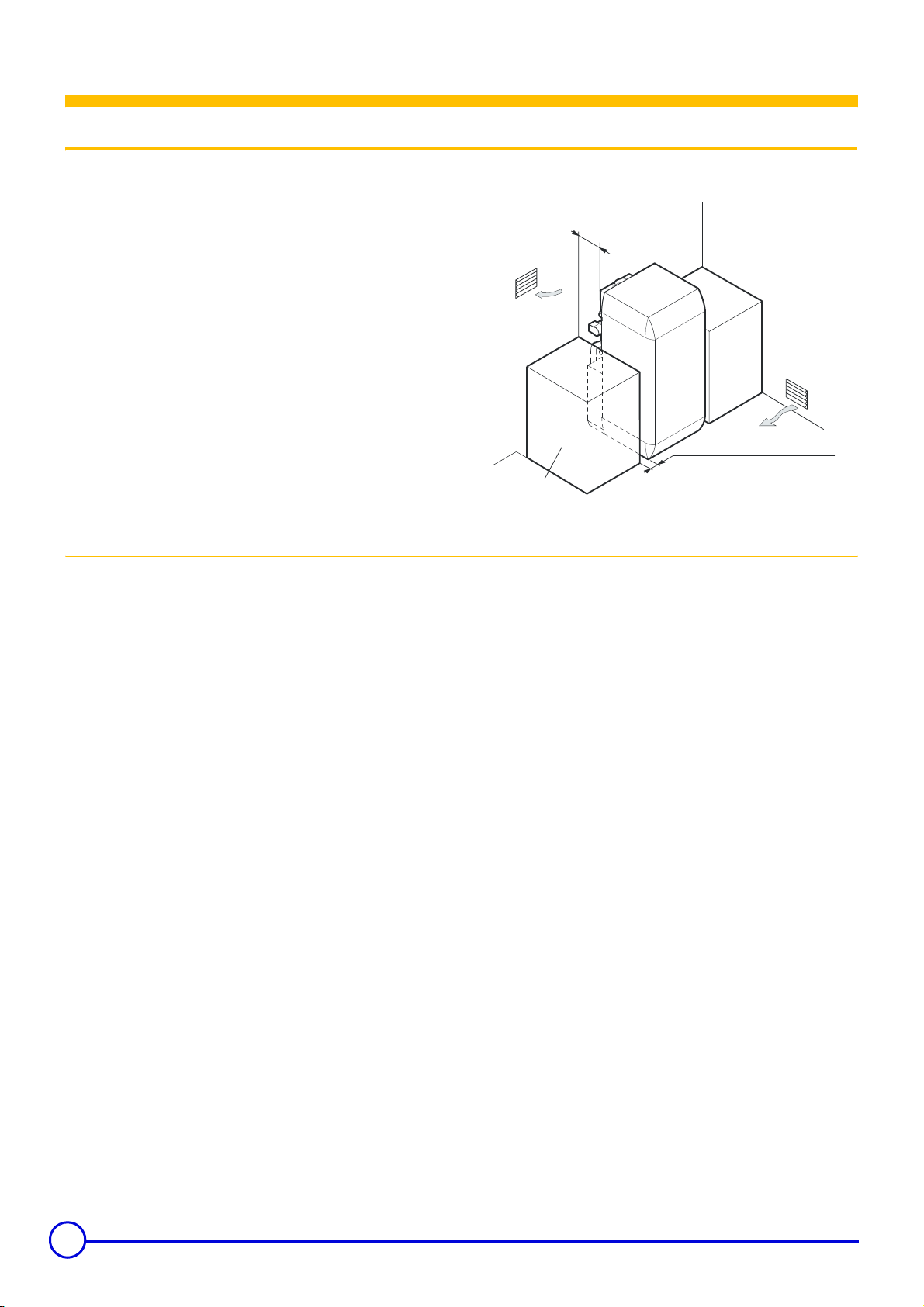
1 Implementation
The boiler can be installed :
- in the kitchen,
- in the cellar,
- in the boiler house.
It is necessary to have in every case :
- 5 cm on one of the boiler sides,
- 70 cm minimum in front,
- and 5 at the rear.
Also have the required space for installing the expansion reservoir
and the heating circulator.
5 cm from the
cm to the left or rig
Furniture
82518N07
1.1 Ventilation
The ventilation section, obligatory in the location where the heater is
installed where there is a direct air inlet must conform with the DTU
61.1 (P45-204) standard and in particular with the instruction on
general management (Book 1764, April 1982).
In order to avoid damage to the boilers, it is necessary to
prevent the contamination of combustion air by chlorine
and/or fluoride compounds, which are particularly
corrosive.
These compounds are present, for example, in aerosol sprays,
paints, solvents, cleaning products, washing products, detergents,
glues, snow clearing salts, etc.
Therefore :
- Do not suck in air evacuated from premises using such products:
hairdressing salons, dry cleaners, industrial premises (solvents),
premises containing refrigeration systems (risk of refrigerant
leakage), etc.
- Do not stock such products close to the boilers.
If the boiler and/or peripheral equipment are corroded by such
chloride or fluoride compounds, the contractual guarantee
cannot be applied.
10
DTG 1300 Eco.NOx/V 23/06/05 - 300002940-001B
Page 11
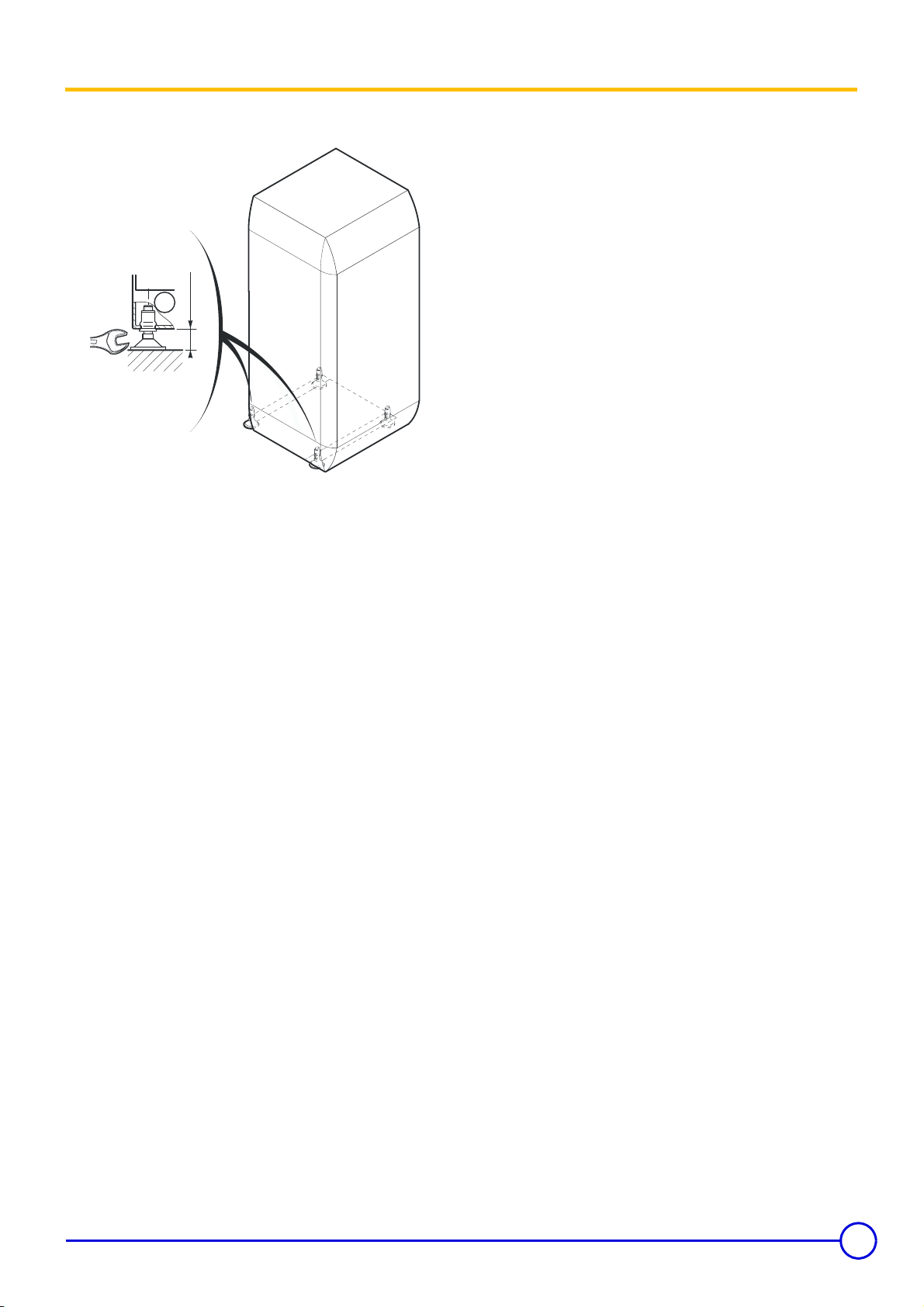
2 Levelling
Levelling is done using the 4 feet located on the heater socket and
using a flat screwdriver.
17
Lift the tank slightly with a lever to adjust the feet.
(1)
Adjustable feet : Basic dimension 40 mm. Can be adjusted from
40 mm
880351N7
40 mm to 55 mm.
23/06/05 - 300002940-001B DTG 1300 Eco.NOx/V
11
Page 12
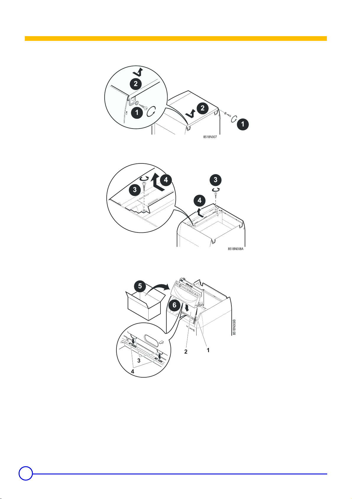
Control panel assembly
The command panel is attached as follows :
1. Unscrew the 2 mounting screws at the back of the column head. 2. Remove the upper casing of the boiler.
3. Unscrew the 2 mounting screws from the screen
5. Take the command panel out of its packaging.
6. Slide the panel along the front plate. Push the 1 tubes through the
lower opening on the panel case.
. 4. Take out the shutter + screen assembly.
12
DTG 1300 Eco.NOx/V 23/06/05 - 300002940-001B
Page 13

7. Take out the heater door.
`Keep the position of the contact spring with relation to the bulbs.
8. Place the bulbs in the sensor tube in front of the boiler. Push them
into the funnel until it butts against it.
9. Use the contact spring 5 for the sensor tube if bulbs 6 are on
number 2.
11. Push the screen support against the front plate.
12. Tighten the 2 pre-assembled plate screws after having pushed
the support fixing wings against the screws.
`Tighten the assembly before engaging the glove finger.
If there are 4 bulbs, the sensor tube contact spring is useless.
10. Then carefully fold the tubes and replace the traction stop tongue in the funnel.
23/06/05 - 300002940-001B DTG 1300 Eco.NOx/V
13
Page 14

13. Attach the burner cable to the 12 connector studs located on the
inner face of the command panel.
16. Attach the anti-release safety device onto the 3 connector studs on the command panel.
14. Connect the earth cable to the clip located on the front plate.
15. Open the side of the panel.
17. Close the panel front. 18. Re-assemble the shutter * screen assembly.
Connect the panel's electrical connections according to the
Z
panel's instructions
19. Thread the connection label into the screen slots. Correctly place the label using the truncated corner 7.
14
DTG 1300 Eco.NOx/V 23/06/05 - 300002940-001B
Page 15

20. Screw the panel front onto the screen using a mounting screw. Re-assemble the door and the column head.
23/06/05 - 300002940-001B DTG 1300 Eco.NOx/V
15
Page 16

Connecting the furnace
1 Hydraulic connections
Installation must be carried out in accordance with the prevailing
regulations, the codes of practice and the recommendations in these
instructions.
1.1 Important recommendations for connecting the boiler to the heating circuit
There must be no total or partial closing mechanism
between the boiler and the safety valves (France: DTU -
65.11, § 4.22 - NF P 52-203).
Heating installations must be designed and implemented
to prevent heating circuit water and products contained in
it returning to the drinking water system (article 16-7
Departmental Health Regulations). A CB disconnector
(area disconnector for different uncontrollable
pressures)must be installed for filling the heating circuit
according to the NF P 43-011 standard.
Prior connecting the heating circuit hydraulic connections, it is vital
that the heating circuits are rinsed to prevent articles that may
damage certain parts from being introduced (safety valves, pumps,
non return valve...).
1.2 Hydraulic connection of the water circuit for domestic use
Please see the document delivered with the domestic hot water
Z
preparer.
2 Connecting the gas channel
Each time, a blocking tap will be located as near as possible to the
heater.
In the event where the burner is located at the highest point in the
installation, a dry running or water pressure control device my be
fitted.
Take care to ensure the hydraulic isolation of the primary and
secondary circuits using stop valves in order to facilitate maintenance
operations on the calorifier. These are used to carry out maintenance
on the tank and its systems without draining the entire installation.
These valves are also used to isolate the calorifier when conducting
a pressurised check on the leak tightness of the installation if the test
pressure for the calorifier is greater than the admissible operating
pressure.
IN ORDER TO FACILITATE BLEEDING, the installation must
be filled via the drainage/filling valve
Pipe diameters must be defined in accordance with ATG's
(Association Technique de Gaz) B171 specifications.
The load loss between the meter and heater must be lower than 1
mbar (heater operating).
Equipment pressure supply values :
- Natural gas H/E (G20) : 20 mbar
- Natural gas L/LL (G25) : 25 mbar
- Propane (G31) : 37 mbar
The boilers leave the factory operating with H/E natural gas. For
operating with natural gas L or propane, carry out the actions
described in the chapter "Adapting to another gas".
16
DTG 1300 Eco.NOx/V 23/06/05 - 300002940-001B
Page 17

3 Connecting to a chimneye
The equipment must be installed following the codes of practice
using sealed stainless steel, aluminium or internally meshed tubing
capable of withstanding hot combustion gases and any likely acid
condensation.
1
4 Electrical connections
Connections must be made by a qualified technician.
Connections inside the command panel must not be
modifed in any way.
2
The pipe must be laid out to allow any likely condensation to drain.
It must be in accordance with existing regulations for pipes used for
this purpose. Standard meshed connection pipes are to be avoided.
The pipe connecting the outlet conduit must also be as short as
possible and without a reduced diameter.
The vertical section of the draught diverter outlet must be a minimum
length 3x the diameter of the nozzle before an elbow joint is fitted.
The pipe must have a diameter not less than the heater's nozzle
diameter along its whole length.
This pipe must be able to be easily disassembled and must not have
a sudden change in diameter.
The outlet conduit must be maintained in a good condition, checked
and cleaned at least once a year.
Boiler Good
Boiler Poor
Keep to the polarity shown on the terminals : phase (L),
neutral (N) and earth
4
.
23/06/05 - 300002940-001B DTG 1300 Eco.NOx/V
17
Page 18

Adapting to another gas
Operations to be carried out to allow the change from H/E natural gas
to L/LL natural gas or to propane and vice versa.
The actions described below must be carried out by a
qualified technician.
Check the seals for the gas.
1 Attaching the label
This indicates the type of gas for which the burner is set.
2 Changing the burner injectors
Lift out the injector with a number 12 spanner assemble the new
injectors with their new joint.
Conversion kits
Natural gas H/E
Natural gas L/LL
Propane
Nozzle marking
Natural gas H/E 210B 2,10
Natural gas L/LL 245B 2,45
Propane 140A 1,40
Package GL34
8518-7007
Package GL31
8518-7004
Package GL32
8518-7005
Nozzle diameter
(mm)
3 Changing the ignition burner injector
.
4
Prior to re-assembling the injector for each burner also replace
the aluminium joint. First tighten the injectors by hand and
carefully lock them using a spanner.
Nozzle marking
3
1
Natural gas H/E 4 0,40
Natural gas L/LL
(France)
Natural gas L
≠ France)
(
Propane 3 0,30
40,40
50,50
Nozzle diameter
(mm)
Unscrew the connecting nut (14 spanner),
Pull the gas supply pipe towards yourself.
Take out the ignition burner nozzle.
Fit the new nozzle .
Re-attach the supply tube (14 spanner)
18
France:The 40 mm ignition burner injection fitted in the factory
is suitable for operation on natural gas H/E and L/LL (no
conversion necessary for switching from H/E to L/LL and vice
versa).
DTG 1300 Eco.NOx/V 23/06/05 - 300002940-001B
Page 19

4 Setting the injector pressure
5 Pressure settings and calibrated injector markings
`Connect a manometer to the pressure socket located on the
manifold.
`Remove the protective cover C on the regulator by unscrewing
it using a screwdriver.
`Set the pressure on the injectors by moving the gas regulator on
the valve.
Manifold pressure (mbar)
Natural gas H 15
Natural gas L 12,1
Propane 29
Number of parts in the heater 4 5 6
Nozzle H/E 210B 210B 210B
Nozzle L/LL 245B 245B 245B
Nozzle Propane 140A 140A 140A
Manifold pressure H/E mbar 15 15 15
Manifold pressure L/LL mbar 12,1 12,1 12,1
Manifold pressure
Propane
Gas flow rate H/E
Gas flow rate L/LL
Flow rate Propane Kg/h 1,56 2,07 2,59
mbar 29 29 29
3
m
m3/h
2,13 2,83 3,52
/h
2,47 3,29 4,10
Flows are stated at 15°C - 1013 mbar.
Setting the start up pressure
E Protective hood
F Ionisation probe connection
G Ignition electrode connection
Start up pressure may be set if necessary using a flat screwdriver,
after the protection has been removed E.
Start up pressure is set in the factory on minimum. If it is necessary
to optimise heater start up, it may be set on another value between
0º and 270º.
Gas valve opening diagram
Downstream pressure
23/06/05 - 300002940-001B DTG 1300 Eco.NOx/V
Time (seconds)
19
Page 20

1 Refilling the installation
Aut
Dh
V
Aut
Commissionning
Firstly, fill the tank with domestic hot water.
Domestic hot water circuit
- Fill the calorifier via the cold water input pipe. If necessary, rinse
the domestic circuit (particularly when commissioning), allowing
the water to flow for a certain amount of time.
- Bleed the domestic circuit (tank and distribution network); to do
this:
- Completely fill the calorifier with water, leaving the hot water valve
open; close this valve only when the flow is regular and there is no
noise in the pipes.
- Then successively degas all the hot water pipes by opening the
corresponding valves in order to prevent the noise caused by air
movement when drawing off water.
- Check the safety devices (particularly the valve or safety unit),
referring to the instructions provided with these components.
When reheating domestic hot water, a certain amount of water
may escape via the valve or the safety unit because of the
expansion of the water in the calorifier. There is no cause for
concern at this absolutely normal phenomenon, which must in
no event be hindered.
Heating circuit
The heating circuit (boiler and tank exchanger) must be filled using
the drainage tap to the rear of the tank. When filling the heating
circuit, correctly bleed the exchanger on the domestic water calorifier
as follows::
Unscrew the cap on the automatic bleed valve by a few turns
Ensure that the non-return angle valve is in the automatic
position
Ensure that the drainage tap is in the open position
Fill the low flow heating circuit using the drainage tap in order to
favor the bleed
After filling the installation, close the drainage tap
Unstick the load pump in necessary: to do this, unscrew the
protection cap in front of the pump and insert a screwdriver into the
slit (V) on the pump center line. Turn several times to the right and
left.
- Cold run the pump for a few minutes to enable priming.
- The heating circuit must be bled from the highest point of the
installation using a suitable bleeding device (not provided).
omatic
bleed valve
1
6
w pump
85 7518N0
0
2
omatic
position
3
2 Final checks before commissioning
Check the following points before starting the heater :
- Check that the equipment is properly set for the type of gas used.
The boilers leave the factory operating with H/E natural gas.
- Check the gas pressure upstream from the boiler.
- Check the seals on the gas and water connections.
20
DTG 1300 Eco.NOx/V 23/06/05 - 300002940-001B
Page 21

3 Commissionning
The first start-up is to be performed by your installation
engineer.
- Open the gas blocking tap.
- Check that the safety thermostat has not triggered. Remove the
safety thermostat hood and press the reset button with a
screwdriver.
- Place the stop/start switch
4 Furnace operation equipped with safety box 577 DBC
The ignition and burner surveillance sequences are ensured by the
safety box.
Normal operating cycle
on On.
8
Operating principle
- Create a requirement for heat.
Please consult the document delivered with the command
Z
panel before carrying out any action with it.
- The safety box carries out its ignition cycle.
Switching off : Place the start/stop switch on Off.
Operating cycle on safety (start up without flame signal)
Required input signals
Box output signals
Contact closed
The box closes the TCH contact when there is a requirement for heat.
The ignition transformer TA integrated into the safety control box and
the ignition burner valve VBA (supply to the ignition burner) are
switched on.
Gas from the ignition burner is ignited by the ignition electrode and
within the time interval ts; a minimum current of 0.3 µA appears on
the ionisation sensor SF and the gas valve regulation flap (supplying
the principal burner) opens.
Required input signals
Box output signals
Contact closed
- If a flame is not detected before the safety time ts, the box makes
2 more ignition attempts. If, at the end of the last attempt, there is
still no flame signal, the box goes into safety and the safety
indicator comes on. To restart the heater, press the reset button on
the safety box.
- If there is a loss of flame in normal operation, the box automatically
repeats the start up sequence.
Resetting : The box is reset after going into safety by pressing the
reset button. If the reset button does not work, wait at least 15
seconds before trying a second time.
The box may be on safety on its first start up : press the reset
button to release it.
If the reset button is pressed in normal operation, the gas valves
close and the box starts a new ignition sequence.
23/06/05 - 300002940-001B DTG 1300 Eco.NOx/V
21
Page 22

Operating cycle with the anti-smoke release thermostat cut
off
Required input signals
Box output signals
Contact closed
In the event of smoke release, the burner is cut and the boiler goes
into standby for 15 minutes. This timed phase is indicated by an
alarm indicator flashing. The 15 minute timed period can only be
interrupted by a sector cut.
Key :
A Start of operation
A
1
A
2
Second ignition attempt
Third ignition attempt
B Formation of flame in ignition burner
C End of first ignition attempt
C
1
C
2
End of second ignition attempt
On safety through absence of flame signal
D Smoke anti-release thermostat cut
E Resetting
F Restart of heater
SF Burner flame signal
VA Alarm indicator
TA Ignition transformer
TAF Anti-backflow thermostat
TCH Heat requirement
VBA Ignition burner valve
VBP Main burner valve
ts Safety time : about 55 seconds
tn Anti-smoke release thermostat cooling time (times
vary)
t
TAF
Box standby time : 15 minutes
5 Checks and adjustments after commissioning
5.1 Checking pressure to the nozzle
`Unscrew the screw inside the nozzle pressure socket a few
turns.
`Connect a manometer to the pressure socket and check that
the pressure to the socket corresponds to the pressure stated
below. Adjust the pressure to the injectors if necessary.
`Tighten the pressure socket screw.
`Check the seal again
Manifold pressure (mbar)
Natural gas H/E 15
Natural gas L/LL 12,1
Propane 29
Checking burner safety
Cut the gas by closing the stop tap.
Check the reaction of the safety system. (Safety box on safety
because of ionisation fault).
Checking the safety thermostat
`Place the Summer/Winter switch on
to cut the heating
%
accelerator to prevent the temperature rising in the installation.
`Place the 3 position switch "
- AUTO - TEST STB" on the
!
TEST STB position. The burner starts regardless of the setting.
Keep the switch in this position until the safety thermostat cuts
(110ºC).
`To restart the heater, press the safety thermostat reset button
and repeat the starting operations.
22
DTG 1300 Eco.NOx/V 23/06/05 - 300002940-001B
Page 23

Checking the anti-smoke release thermostat
In the event of smoke release by the anti-blowback device, the antirelease safety device switches off the burner with the safety box on
standby for 15 minutes (this is indicated by an alarm indicator
flashing).
Checking procedure :
Turn of the heater and take out the smoke duct linking the heater to
the chimney. Close off the smoke duct to the heater using a metal
sheet (or other heat proof material).
On start up, combustion products are evacuated to the back of the
heater by the anti-blowback device opening inside.
The anti-blowback thermostat triggers for a few seconds, cuts the
burner and starts the safety box timer (alarm indicator flashing).
After checking, re-assemble the smoke duct connecting the heater to
the chimney.
Wait for about 5 minutes (thermostat cooling time) the cut and
reconnect the current using the Start/Stop switch. The boiler restarts.
23/06/05 - 300002940-001B DTG 1300 Eco.NOx/V
23
Page 24

Maintenance
1 Cleaning main burner and ignition burner
The main burner and the ignition burner injector with its filter must be
regularly cleaned to ensure good performance. Il est conseillé de le
faire au moins 1 fois par an.
1
Ionisation probe
2
Ignition electrode
3
Flame diffuser
4
Earth electrode
Main burner
Switch off the boiler electrical power supply
Cut the gas supply.
Open the heater door
Disconnect the burner connector under the command panel
Unscrew the union joint on the gas inlet pipe
Unscrew the screws
Take out the burner earth wire
Disassemble the burner drawer
Clean the burner with a brush, a vacuum cleaner or a blower
Do not use a metal brush !
- Re-assemble the burner earth wire
Ignition burner
Unscrew the connecting screw, then pull the gas supply pipe
towards you
Take out the injector and the filter
Remove ionisation probe 1 and the earth electrode 4 deposits
(for example using sand paper)
- Re-attach the supply tube (14 spanner),
- Check the position of the ionisation probe 1, the ignition electrode
gap 2 and the position of the flame diffuser 3 in terms of the sizes
indicated on the drawing (required in the event of heater
malfunction).
Check the seals for the gas.
24
DTG 1300 Eco.NOx/V 23/06/05 - 300002940-001B
Page 25

2 Cleaning heater body
8518N016
`Sweep the heater.
`Take out the burner drawer from the heater body.
1
2
`Do not block the gas ramp openings.
With the burner out :
Take out the column head fixed by 2 screws and toothed washers
Take out the insulation
Open the sweeping trap by unscrewing the 2 screws
Clean the heater body with the special brush delivered with the
product.
To re-assemble, perform the above actions in reverse order.
3
4
3 Maintenance
Maintenance and cleaning of the heater must be carried out at least
once a year by a qualified technician.
Stages Actions
Water level Regularly check the level of water in the system and top up if required, taking care that cold water is not
added suddenly into the boiler when it is hot.
This operation must be carried out several times per season ; if not, look for the probable leak and
immediately fix it.
Ice In the event that the heating stops during winter, increasing the risk of ice (holiday home for example), it is
recommended that sufficient anti-freeze is used to stop the heating water from freezing.
As a default, completely empty the installation (check with your installation engineer).
We advise you against draining the system unless it is
absolutely necessary (For example : Several months' absence
with the risk of ice in the building).
4 Periodic checks on the domestic hot water tank
Titane anode
No maintenance operations
The panel must be switched on to ensure that the anode is
working
Magnesium anode
The titanium anode can be replaced by a magnesium anode.
It is recommended that you take out a maintenance contract with a
qualified installation engineer. In the event that this is not possible,
sign a maintenance contract with an after-sales service company
recommended by your installation engineer or De Dietrich.
Sweeping the smoke conduct and the purge tank must be carried out
at least once a year during boiler maintenance.
The magnesium anodes must be checked at least every 2, years.
After the first check, determine the frequency of future checks on the
basis of anode wear. The anodes can be checked by two methods:
- Inspection:
the anode must be replaced if its diameter is less than 15 mm
(original diameter = 33 mm)
- Function test:
- disconnect the earth wire from the anode
23/06/05 - 300002940-001B DTG 1300 Eco.NOx/V
25
Page 26

- measure the strength of the cu rrent between the tank and the
anode ; if the current measured is less than 0.1 mA, the anode
should be replaced.
Valve or safety unit
The safety unit must be periodically manoeuvred (at least
once a month). To do this, put the safety unit in the
drainage position. This manoeuvre evacuates any
desposits which may in time block the safety unit valve.
Failure to comply with this maintenance rule may cause
damage to the tank structure.
In hard water regions, we recommend descaling the tank annually in
order to maintain its performance.
- Remove limescale deposits in the form of sludge or strips in the
bottom of the tank. On the other hand, do not touch limescale
adhering to the walls of the tank as it provides effective protection
against corrosion and improves the insulation of the DHW tank.
- The exchanger will have to be descaled, if need be, in order to
maintain optimum performance.
4.1 Operations to be carried out to check or replace the anode and descale the installation
Descaling
The TAS titanium anode (standard)
6x
13
8185N101
The magnesium anode (optional)
1. Fit a new watertight seal to the calorifier flange
2. Cut the power supply to the boiler
3. Cut off the cold water supply and drain the DHW tank. To drain
though the safety unit, turn the unit to drain and turn on a hot
water tap (or a bleed valve) to allow air to enter.
4. Remove the front panel and the sensors.
5. Remove the cover (13 mm spanner).
6. Check the anode and replace it if necessary.
7. When reassembling, replace the watertight seal; to do this:
- Replace the lip seal and position it in the visit opening, making
sure that you place its lug outside the DHW tank.
- Position the retainer ring around the seal, making sure you place
the lug above the retainer ring.
- Fix the cover to the flange using *1 screws, tightening them
uniformly in a cross pattern.
8. Proceed with filling according to the instruction in the chapter "Commissioning". Check the seal and the safety devices on the calorifier after reassembly.
The flange mounting bolts must not be excessively tight:
6N.m±
Nota: Approximately 6 Nm is obtained by holding the box
: use a torque wrench.
@
spanner by the small lever.
26
8 18 0775N
6x
13
DTG 1300 Eco.NOx/V 23/06/05 - 300002940-001B
Page 27

Incidents and solutions
Symptoms Probable causes Solution
The heater does not start
and the safety box is not
affected (red alarm
indicator off)
The burner does not
ignite and the safety box
is not affected (red alarm
indicator off)
The burner ignites and
the safety box goes into
standby (burner cut and
the alarm indicator
flashes)
The burner ignites and
the safety box is affected
(alarm indicator on)
The burner ignites but
with reduced power
Dirty cast iron body
(hearth)
Noisy heater
- The heater thermostat is
requiring heat
- Setting (option) is not requiring
heat.
- The safety thermostat has been
triggered after overheating.
- No current - Place the Stop/Start switch on "On"
- On safety because of a lack of
gas
- Faulty gas valve - Check the gas valve and replace if necessary.
- No spark from the electrode - Check the electric cable connection to the safety box and the electrode
- No ionisation current - Check the ionisation probe and earth wire connection.
- Blocked filter or ignition burner
injector
- Anti-blowback thermostat cut - Check the draught in the chimney connection, check the condition of the
- Inversion of the phase and
neutral wires on the heater's
command panel
- Upstream pressure too weak - Check gas supply
- Dirty filter - Clean the filter
- Unsuitable injectors (See Table
"Pressure setting and marking of
calibrated injectors")
- Faulty gas valve - Check gas valve and replace if necessary
- Injectors too small - Check them (See Table "Pressure setting and marking of calibrated
- Upstream pressure too high - Revoir l’alimentation en gaz
- Dirty burner - Clean the burner
- Insufficient or poorly placed air
supply
- Faulty gas valve - Check gas valve and replace if necessary
- Poor purge - Purger correctement
- Body has scale - Détartrer le circuit chauffage
- Unsuitable injectors (Whistling) - Check injectors
- Create a demand by moving the heater thermostat or the setting level
(option).
- Solve the cause of overheating and reset the safety thermostat.
- Purge the gas supply pipe then reset the heater using the panel reset
button
- Check the position of the ionisation probe and the flame diffuser in the
ignition burner
- Clean the filter and the ignition burner injector
anti-blowback thermostat, then press the Start/Stop button to cancel the 15
timer and restart the heater
- Please note the seriousness of unplanned intervention on the combustion
product evacuation checking device : evacuation faults must be solved by
improving the draught in the chimney.
- In the event of a thermostat fault, it must be replaced by a part stated on
our "Spare parts list". Its position must not be modified, which is defined by
the 2 bosses on the holding bracket which are located in the 2 holes on the
draught diverter. The thermostat must not be placed out of service.
- Connect the phase to terminal 1 and neutral to 2.
- Check them
injectors")
- Enlarge air supply, smoothen airation holes
- Burner clogged by building dust
23/06/05 - 300002940-001B DTG 1300 Eco.NOx/V
27
Page 28

Symptoms Probable causes Solution
Heater too hot or too cold
for requirements
Flame returns - Injectors too large
- 3 position switch on position !- Check the position of the 3 position switch
- Wrong setting for the heater
thermostat
- Set the heater thermostat if the heater has SV-matic setting or an ambient
thermostat
- Check pressure injectors
- Pressure too weak
Whistling
- Injectors too small
- Check pressure injectors
- Pressure too high
28
DTG 1300 Eco.NOx/V 23/06/05 - 300002940-001B
Page 29

To order a spare part, quote the reference number next to the part required.
Domestic hot water tanks
1
12
13
2
4
5
8
3
9
11
6
7
14
10
23/06/05 - 300002940-001B DTG 1300 Eco.NOx/V
29
Page 30

.
Boiler body + Draught diverter + Insulation
Spare parts - DTG 1300 Eco.NOx/V
23/06/05 - 300002940-002A
26
27
33
34
35
28
32
28
29
23
25
30
31
24
22
39
36
37
41
38
40
85 15118N
DE DIETRICH THERMIQUE S.A.S. - Spare parts centre
4, rue d’Oberbronn - F-67110 REICHSHOFFEN - Tél. : (+33) 03 88 80 26 50 - Fax : (+33) 03 88 80 26 98
cpr
dedietrichthermique.com
Page 31

Gas line
Cladding
23/06/05 - 300002940-001B DTG 1300 Eco.NOx/V
31
Page 32

Linking kit
32
DTG 1300 Eco.NOx/V 23/06/05 - 300002940-001B
Page 33

Rep Code no. Description
Tank
1 8955-5509 LI130 foam for DTG 1304 and 1305 Eco.NOx/V
1 8955-5510 LI130 foam for DTG 1306 Eco.NOx/V
2 8970-5511 7 mm seal kit
3 200000092 Complete buffer tank
4 200000093 Complete Anode
5 9501-3023 20x8.5x2 vitron seal
6 9497-4525 Ny lo n sp a cer
7 200000049 Connector
8 9536-5009 Sensor attachment lug
9 9786-0646 Adjustable foot
10 8955-4026 Insulation, buffer tank
11 8518-8686 Upper angle fastening, length 644
11 8518-8687 Upper angle fastening, length 744
12 9501-3010 Gasket 29x19x3
13 9501-3011 Gasket 29x15x3
14 8801-4965 TAS anode cable, length 2 m
15 8801-4963 Titan_Active_System_® simulation connector
Boiler body
22 8375-5507 Assembled boiler body - 4 sections
22 8375-5508 Assembled boiler body - 5 sections
22 8375-5509 Assembled boiler body - 6 sections
23 8518-8025 Front mounting square
24 9536-5611 Sensor tube
25 8375-0004 Body lifter
26 9754-9933 Straight 1" pipe
27 9494-6190 Nipple N280 1"
28 9492-0297 ElbowNr. 92 1"
Draught diverter
29 8518-8515 Draught diverter complete - 4 sections
29 8518-8516 Draught diverter complete - 5 sections
29 8518-8517 Draught diverter complete - 6 sections
30 9758-1501 Flue gas nozzle Ø 110/111
30 300000300 Staged smoke nozzle Ø 125/130
30 300000301 Staged smoke nozzle Ø 150/153
31 8518-8054 Inspection hatch - 4 sections
31 8518-8055 Inspection hatch - 5 sections
31 8518-8056 Inspection hatch - 6 sections
32 200000204 Anti-backflow thermostat complete
33 8375-8077 Mounting square
34 9536-3355 Static thermostat
Rep Code no. Description
35 200000095 Electric circuit - Anti-backflow thermostat
36 8366-5501 Body screws packet + Draught diverter
Insulating material for body
37 200000522 Complete insulating material for body - 4 sections
37 200000523 Complete insulating material for body - 5 sections
37 200000524 Complete insulating material for body - 6 sections
38 9755-0514 Insulation under burner - 4 sections
38 9755-0515 Insulation under burner - 5 sections
38 9755-0516 Insulation under burner - 6 sections
39 8388-5656 Insulation back of hearth - 4 sections
39 8388-5657 Insulation back of hearth - 5 sections
39 8388-5658 Insulation back of hearth - 6 sections
40 9428-5095 Silicone filler tube
41 9696-0227 Brush
Gas circuit
52 200003132 Gas circuit complete - 4 sections
52 200003133 Gas circuit complete - 5 sections
52 200003134 Gas circuit complete - 6 sections
54 8518-5508 FURIGAS b urner drawer - 4 sections
54- 8518-5509 FURIGAS burner drawer - 5 sections
54 8518-5510 FURIGAS b urner drawer - 6 sections
56 8388-5533 FURIGAS burner + Screws
57 9536-0220 Pressure socket
58 8375-4945 Earth cable
60 8518-8922 Complete ignition burner - 4-6 sections
62 8518-5515 Ignition burner gas supply pipe - 4-6 sections
63 8518-5516 Valve
64 8518-5517 Elbow flange 1/2" + Gasket
66 9502-3314 Gasket
67 8518-5519 Box + Wiring
68 8518-4904 Burner cable
69 9495-2101 N174 1/2" x 1" nut
70 9495-2081 Moving part N3 71 1/2"
71 9501-3062 Green joint 30 x 21 x 2
72 9754-9898 Gas inlet pipe - 3 to 6 sections
74 8388-5636 Burner drawer insulation kit 4 sections
74 8388-5637 Burner drawer insulation kit 5 sections
74 8388-5638 Burner drawer insulation kit 6 sections
76 8366-5502 Screws
77 8518-7007 Conversion set H/E - Package GL34
23/06/05 - 300002940-001B DTG 1300 Eco.NOx/V
33
Page 34

Rep Code no. Description
Cladding
86 8518-8631 Cladding - 4 sections
86 8518-8632 Cladding - 5 sections
86 8518-8633 Cladding - 6 sections
87 8518-8640 Front plate - 4 sections
87 8518-8641 Front plate - 5 sections
87 8518-8642 Front plate - 6 sections
88 8518-8530 Complete right hand side panel
89 8518-8531 Complete left hand side panel
89 9482-0110 Catch
91 8518-8663 Upper rear panel - 4 sections
91 8518-8664 Upper rear panel - 5 sections
91 8518-8665 Upper rear panel - 6 sections
92 8518-8654 Lower back panel - 4 sections
92 8518-8655 Lower back panel - 5 sections
92 8518-8656 Lower back panel - 6 sections
93 8518-8651 Complete rear tank panel Ll110
93 8518-8652 Complete rear tank panel Ll130
94 8518-8549 Complete door
95 9482-0120 Bolt
96 8518-8678 Complete header column
98 8518-8679 Additional part set
99 9752-5376 Funnel
100 9752-5372 Narrow screen
101 9752-5374 Narrow shutter
102 9752-5370 Narrow body
Rep Code no. Description
198 9536-2447 KVT sensor
199 8575-4909 DHW connector
Linking kit
176 9491-4424 1" connection cross
177 9513-2249 UP15-30 circuit
178 9499-4110 Stainless steel hose, length 750
179 8955-4900 Power supply cable load pump
180 8575-4925 DHW connector pump
182 8999-8522 Complete G1 connector + nut
183 9491-4419 Elbow90°
184 9491-4292 Non-return valve
185 9491-4421 Brass reducer
186 8500-0023 Automatic air vent
187 9490-2073 Emptying tap without joint 1/2"
188 9795-0113 Solid plug 1/2"
189 9501-3010 Gasket 29x19x3
190 9495-0198 Plug laiton G1
191 9501-3062 Green seal 30x21x2
34
DTG 1300 Eco.NOx/V 23/06/05 - 300002940-001B
Page 35

Warranty
You have just purchased a DE DIETRICH appliance and we
thank you for the trust you have placed in our products.
Please note that your appliance will provide good service for a
longer period of time if it is regularly checked and maintained.
Your fitter and the DE DIETRICH customer support network are
at your disposal at all times.
Warranty terms
Starting from the purchase date shown on the original fitter's
invoice, your appliance has a contractual guarantee against any
manufacturing defect.
The length of the guarantee is mentioned in the price catalogue.
The manufacturer is not liable for any improper use of the
appliance or failure to maintain or install the unit correctly (the
user shall take care to ensure that the system is installed by a
qualified fitter).
In particular, the manufacturer shall not be held responsible for
any damage, loss or injury caused by installations which do not
comply with the following:
- applicable local laws and regulations
- specific requirements relating to the installation, such as
national and/or local regulations
- the manufacturer's instructions, in particular those relating to
the regular maintenance of the unit
- the rules of the profession
France
The preceding dispositions are not exclusive of benefits for the
purchaser of the legal guarantee as stated in Civil Code articles
1641 to 1648.
Belgium
The preceding dispositions about the contractual guarantee are
not exclusive of profit if the need arises for the purchaser in
Belgium of the applicable legal dispositions on hidden defects.
Switzerland
The application of the warranty is subject to the terms and
conditions of sale, delivery and warranty of the company
marketing DE DIETRICH products.
Other countries
The above provisions do not restrict the benefit of the legal laws
regarding hidden defects applicable in the buyer's country.
The warranty is limited to the exchange or repair of such parts as
have been recognised to be faulty by our technical department
and does not cover labour, travel and carriage costs.
The warranty shall not apply to the replacement or repair of parts
damaged by normal wear and tear, negligence, repairs by
unqualified parties, faulty or insufficient monitoring and
maintenance, faulty power supply or the use of unsuitable fuel.
Sub-assemblies such as motors, pumps, electric valves etc. are
guaranteed only if they have never been dismantled.
23/06/05 - 300002940-001B DTG 1300 Eco.NOx/V
35
Page 36

36
DTG 1300 Eco.NOx/V 23/06/05 - 300002940-001B
Page 37

DTG 1300 Eco.NOx/V 23/06/05 - 300002940-001B
Page 38

DTG 1300 Eco.NOx/V 23/06/05 - 300002940-001B
Page 39

DTG 1300 Eco.NOx/V 23/06/05 - 300002940-001B
Page 40

FR
DE DIETRICH THERMIQUE S.A.S.
www.dedietrich.com
Direction des Ventes France
57, rue de la Gare
F- 67580 MERTZWILLER
+33 (0)3 88 80 27 00
+33 (0)3 88 80 27 99
AT
DE DIETRICH HEIZTECHNIK
www.dedietrich.com
Am Concorde Park 1 - B 4 / 28
A-2320 SCHWECHAT / WIEN
+43 (0)1 / 706 40 60-0
+43 (0)1 / 706 40 60-99
office@dedietrich.at
DE
BE
CH
DE DIETRICH HEIZTECHNIK
www.dedietrich.com
Rheiner Strasse 151
D- 48282 EMSDETTEN
+49 (0)25 72 / 23-5
+49 (0)25 72 / 23-102
info@dedietrich.de
VAN MARCKE
www.vanmarcke.be
Weggevoedenlaan 5
B- 8500 KORTRIJK
+32 (0)56/23 75 11
VESCAL S.A.
www.chauffer.ch / www.heizen.ch
Z.I de la Veyre, St-Légier
1800 VEVEY 1
+41 (0)21 943 02 22
+41 (0)21 943 02 33
LU
RU
CN
NEUBERG S.A.
www.dedietrich.com
39 rue Jacques Stas
L- 2010 LUXEMBOURG
+352 (0)2 401 401
DE DIETRICH
www.dedietrich.com
8 Gilyarovskogo Str. 7
R- 129090 MOSCOW
+7 495.974.16.03
+7 495.974.66.08
dedietrich@nnt.ru
DE DIETRICH
www.dedietrich.com
Room 512, Tower A, Kelun Building
12A Guanghua Rd, Chaoyang District
C-100020 BEIJING
+86 (0)106.581.4017
+86 (0)106.581.4018
+86 (0)106.581.7056
+86 (0)106.581.4019
contact
BJ
@dedietrich.com.cn
In the interest of customers, DE DIETRICH THERMIQUE are continuous ly endeavouring to make improvements in produc t quality. All the specifications stated in this document are therefore s ubject to change w ithout notice
DE DIETRICH THERMIQUE
57, rue de la Gare F- 67580 MERTZWILLER - BP 30
www.dedietrich.com
AD001Z • 02.2006
 Loading...