

Page 1

EASYLIFE
S U S T A I N A B L E C O M F O R T
®
Neovo
MW-8000030-5
Australia Jordan Lebanon Serbia Syria
en
User Manual
Oil-fired condensing boiler
NeOvo Condens
EFU C–S 19 FF
EFU C–S 24 FF
EFU C–S 32 FF
Page 2

Dear Customer,
Thank you very much for buying this appliance.
Please read through the manual carefully before using the product, and keep it in a safe place for later reference. In order to
ensure continued safe and efficient operation we recommend that the product is serviced regularly. Our service and customer
service organisation can assist with this.
We hope you enjoy years of problem-free operation with the product.
Page 3

Contents
7718497 - v03 - 04012019 EFU-C S FF 3
Contents
1 Safety . . . . . . . . . . . . . . . . . . . . . . . . . . . . . . . . . . . . . . . . . . . . . . . . . . . . . . . . . . . . . . . . . . . . . . . . . . . . . . . . . . . . . . . . . . . . 5
1.1 General safety instructions . . . . . . . . . . . . . . . . . . . . . . . . . . . . . . . . . . . . . . . . . . . . . . . . . . . . . . . . . . . . . . . . . . . . . . . 5
1.2 Recommendations . . . . . . . . . . . . . . . . . . . . . . . . . . . . . . . . . . . . . . . . . . . . . . . . . . . . . . . . . . . . . . . . . . . . . . . . . . . . . 7
1.3 Liabilities . . . . . . . . . . . . . . . . . . . . . . . . . . . . . . . . . . . . . . . . . . . . . . . . . . . . . . . . . . . . . . . . . . . . . . . . . . . . . . . . . . . . . 8
1.3.1 Manufacturer's liability . . . . . . . . . . . . . . . . . . . . . . . . . . . . . . . . . . . . . . . . . . . . . . . . . . . . . . . . . . . . . . . . . . . 8
1.3.2 Installer's liability . . . . . . . . . . . . . . . . . . . . . . . . . . . . . . . . . . . . . . . . . . . . . . . . . . . . . . . . . . . . . . . . . . . . . . . 8
1.3.3 User's liability . . . . . . . . . . . . . . . . . . . . . . . . . . . . . . . . . . . . . . . . . . . . . . . . . . . . . . . . . . . . . . . . . . . . . . . . . .8
2 Symbols used . . . . . . . . . . . . . . . . . . . . . . . . . . . . . . . . . . . . . . . . . . . . . . . . . . . . . . . . . . . . . . . . . . . . . . . . . . . . . . . . . . . . . 10
2.1 Symbols used in the manual . . . . . . . . . . . . . . . . . . . . . . . . . . . . . . . . . . . . . . . . . . . . . . . . . . . . . . . . . . . . . . . . . . . . .10
2.2 Symbols used on the appliance . . . . . . . . . . . . . . . . . . . . . . . . . . . . . . . . . . . . . . . . . . . . . . . . . . . . . . . . . . . . . . . . . . 10
3 Technical specifications . . . . . . . . . . . . . . . . . . . . . . . . . . . . . . . . . . . . . . . . . . . . . . . . . . . . . . . . . . . . . . . . . . . . . . . . . . . . . 11
3.1 Homologations . . . . . . . . . . . . . . . . . . . . . . . . . . . . . . . . . . . . . . . . . . . . . . . . . . . . . . . . . . . . . . . . . . . . . . . . . . . . . . . 11
3.1.1 Certifications . . . . . . . . . . . . . . . . . . . . . . . . . . . . . . . . . . . . . . . . . . . . . . . . . . . . . . . . . . . . . . . . . . . . . . . . . 11
3.1.2 Oil categories . . . . . . . . . . . . . . . . . . . . . . . . . . . . . . . . . . . . . . . . . . . . . . . . . . . . . . . . . . . . . . . . . . . . . . . . .11
3.2 Technical data . . . . . . . . . . . . . . . . . . . . . . . . . . . . . . . . . . . . . . . . . . . . . . . . . . . . . . . . . . . . . . . . . . . . . . . . . . . . . . . .11
4 Description of the product . . . . . . . . . . . . . . . . . . . . . . . . . . . . . . . . . . . . . . . . . . . . . . . . . . . . . . . . . . . . . . . . . . . . . . . . . . . . 13
4.1 General description . . . . . . . . . . . . . . . . . . . . . . . . . . . . . . . . . . . . . . . . . . . . . . . . . . . . . . . . . . . . . . . . . . . . . . . . . . . .13
4.2 Main components . . . . . . . . . . . . . . . . . . . . . . . . . . . . . . . . . . . . . . . . . . . . . . . . . . . . . . . . . . . . . . . . . . . . . . . . . . . . . 13
4.2.1 Boiler . . . . . . . . . . . . . . . . . . . . . . . . . . . . . . . . . . . . . . . . . . . . . . . . . . . . . . . . . . . . . . . . . . . . . . . . . . . . . . . 13
4.3 Description of the control panel B-Control . . . . . . . . . . . . . . . . . . . . . . . . . . . . . . . . . . . . . . . . . . . . . . . . . . . . . . . . . . 13
4.3.1 Description of the keys . . . . . . . . . . . . . . . . . . . . . . . . . . . . . . . . . . . . . . . . . . . . . . . . . . . . . . . . . . . . . . . . . 13
4.3.2 Description of the display . . . . . . . . . . . . . . . . . . . . . . . . . . . . . . . . . . . . . . . . . . . . . . . . . . . . . . . . . . . . . . . .14
4.4 Description of the control panel IniControl 2 . . . . . . . . . . . . . . . . . . . . . . . . . . . . . . . . . . . . . . . . . . . . . . . . . . . . . . . . . 14
4.4.1 Description of the keys . . . . . . . . . . . . . . . . . . . . . . . . . . . . . . . . . . . . . . . . . . . . . . . . . . . . . . . . . . . . . . . . . 14
4.4.2 Description of the display . . . . . . . . . . . . . . . . . . . . . . . . . . . . . . . . . . . . . . . . . . . . . . . . . . . . . . . . . . . . . . . .14
5 Utilisation with the control panel B-Control . . . . . . . . . . . . . . . . . . . . . . . . . . . . . . . . . . . . . . . . . . . . . . . . . . . . . . . . . . . . . . . 17
5.1 Browsing in the menus . . . . . . . . . . . . . . . . . . . . . . . . . . . . . . . . . . . . . . . . . . . . . . . . . . . . . . . . . . . . . . . . . . . . . . . . . 17
5.2 Start-up . . . . . . . . . . . . . . . . . . . . . . . . . . . . . . . . . . . . . . . . . . . . . . . . . . . . . . . . . . . . . . . . . . . . . . . . . . . . . . . . . . . . . 17
5.3 Shutdown . . . . . . . . . . . . . . . . . . . . . . . . . . . . . . . . . . . . . . . . . . . . . . . . . . . . . . . . . . . . . . . . . . . . . . . . . . . . . . . . . . . 18
5.3.1 Switching off the heating . . . . . . . . . . . . . . . . . . . . . . . . . . . . . . . . . . . . . . . . . . . . . . . . . . . . . . . . . . . . . . . . 18
5.3.2 Stopping domestic hot water production . . . . . . . . . . . . . . . . . . . . . . . . . . . . . . . . . . . . . . . . . . . . . . . . . . . . 18
5.3.3 Shutting down the installation . . . . . . . . . . . . . . . . . . . . . . . . . . . . . . . . . . . . . . . . . . . . . . . . . . . . . . . . . . . . 18
5.4 Frost protection . . . . . . . . . . . . . . . . . . . . . . . . . . . . . . . . . . . . . . . . . . . . . . . . . . . . . . . . . . . . . . . . . . . . . . . . . . . . . . . 18
6 Utilisation with the control panel IniControl 2 . . . . . . . . . . . . . . . . . . . . . . . . . . . . . . . . . . . . . . . . . . . . . . . . . . . . . . . . . . . . . 19
6.1 Browsing in the menus . . . . . . . . . . . . . . . . . . . . . . . . . . . . . . . . . . . . . . . . . . . . . . . . . . . . . . . . . . . . . . . . . . . . . . . . . 19
6.2 Start-up . . . . . . . . . . . . . . . . . . . . . . . . . . . . . . . . . . . . . . . . . . . . . . . . . . . . . . . . . . . . . . . . . . . . . . . . . . . . . . . . . . . . . 19
6.2.1 Description of the PCBs . . . . . . . . . . . . . . . . . . . . . . . . . . . . . . . . . . . . . . . . . . . . . . . . . . . . . . . . . . . . . . . . .20
6.2.2 Selecting a PCB . . . . . . . . . . . . . . . . . . . . . . . . . . . . . . . . . . . . . . . . . . . . . . . . . . . . . . . . . . . . . . . . . . . . 20
6.3 Shutdown . . . . . . . . . . . . . . . . . . . . . . . . . . . . . . . . . . . . . . . . . . . . . . . . . . . . . . . . . . . . . . . . . . . . . . . . . . . . . . . . . . . 21
6.3.1 Switching off the heating . . . . . . . . . . . . . . . . . . . . . . . . . . . . . . . . . . . . . . . . . . . . . . . . . . . . . . . . . . . . . . . . 21
6.3.2 Stopping domestic hot water production . . . . . . . . . . . . . . . . . . . . . . . . . . . . . . . . . . . . . . . . . . . . . . . . . . . . 22
6.3.3 Shutting down the installation . . . . . . . . . . . . . . . . . . . . . . . . . . . . . . . . . . . . . . . . . . . . . . . . . . . . . . . . . . . . 22
6.4 Frost protection . . . . . . . . . . . . . . . . . . . . . . . . . . . . . . . . . . . . . . . . . . . . . . . . . . . . . . . . . . . . . . . . . . . . . . . . . . . . . . . 22
7 Control panel settings B-Control . . . . . . . . . . . . . . . . . . . . . . . . . . . . . . . . . . . . . . . . . . . . . . . . . . . . . . . . . . . . . . . . . . . . . . . 24
7.1 List of parameters . . . . . . . . . . . . . . . . . . . . . . . . . . . . . . . . . . . . . . . . . . . . . . . . . . . . . . . . . . . . . . . . . . . . . . . . . . . . . 24
7.1.1 Information menu . . . . . . . . . . . . . . . . . . . . . . . . . . . . . . . . . . . . . . . . . . . . . . . . . . . . . . . . . . . . . . . . . . . . . .24
7.2 Setting the parameters . . . . . . . . . . . . . . . . . . . . . . . . . . . . . . . . . . . . . . . . . . . . . . . . . . . . . . . . . . . . . . . . . . . . . . . . . 24
7.2.1 Setting the heating water temperature . . . . . . . . . . . . . . . . . . . . . . . . . . . . . . . . . . . . . . . . . . . . . . . . . . . . . .24
7.2.2 Modifying the domestic hot water temperature setpoint . . . . . . . . . . . . . . . . . . . . . . . . . . . . . . . . . . . . . . . . 25
8 Control panel settings IniControl 2 . . . . . . . . . . . . . . . . . . . . . . . . . . . . . . . . . . . . . . . . . . . . . . . . . . . . . . . . . . . . . . . . . . . . . 26
8.1 List of parameters . . . . . . . . . . . . . . . . . . . . . . . . . . . . . . . . . . . . . . . . . . . . . . . . . . . . . . . . . . . . . . . . . . . . . . . . . . . . . 26
8.1.1 User menu . . . . . . . . . . . . . . . . . . . . . . . . . . . . . . . . . . . . . . . . . . . . . . . . . . . . . . . . . . . . . . . . . . . . . . . . . 26
8.1.2 COUNTERS /TIME PROG / CLOCK menus . . . . . . . . . . . . . . . . . . . . . . . . . . . . . . . . . . . . . . . . . . . . . . .28
8.2 Setting the parameters . . . . . . . . . . . . . . . . . . . . . . . . . . . . . . . . . . . . . . . . . . . . . . . . . . . . . . . . . . . . . . . . . . . . . . . . . 30
8.2.1 Modifying the User parameters . . . . . . . . . . . . . . . . . . . . . . . . . . . . . . . . . . . . . . . . . . . . . . . . . . . . . . . . . 30
8.2.2 Setting the heating . . . . . . . . . . . . . . . . . . . . . . . . . . . . . . . . . . . . . . . . . . . . . . . . . . . . . . . . . . . . . . . . . . 30
Page 4

Contents
4 EFU-C S FF 7718497 - v03 - 04012019
8.2.3 Setting the domestic hot water temperature . . . . . . . . . . . . . . . . . . . . . . . . . . . . . . . . . . . . . . . . . . . . . . 31
8.2.4 Setting the timer programming . . . . . . . . . . . . . . . . . . . . . . . . . . . . . . . . . . . . . . . . . . . . . . . . . . . . . . . . . 31
8.2.5 Activating Manual Forcing for heating . . . . . . . . . . . . . . . . . . . . . . . . . . . . . . . . . . . . . . . . . . . . . . . . . . . . 32
8.3 Reading out measured values . . . . . . . . . . . . . . . . . . . . . . . . . . . . . . . . . . . . . . . . . . . . . . . . . . . . . . . . . . . . . . . . . 33
8.3.1 Control system sequence . . . . . . . . . . . . . . . . . . . . . . . . . . . . . . . . . . . . . . . . . . . . . . . . . . . . . . . . . . . . . . . 34
9 Maintenance . . . . . . . . . . . . . . . . . . . . . . . . . . . . . . . . . . . . . . . . . . . . . . . . . . . . . . . . . . . . . . . . . . . . . . . . . . . . . . . . . . . . . . 35
9.1 General . . . . . . . . . . . . . . . . . . . . . . . . . . . . . . . . . . . . . . . . . . . . . . . . . . . . . . . . . . . . . . . . . . . . . . . . . . . . . . . . . . . . . 35
9.2 Maintenance instructions . . . . . . . . . . . . . . . . . . . . . . . . . . . . . . . . . . . . . . . . . . . . . . . . . . . . . . . . . . . . . . . . . . . . . . . 35
9.2.1 Check the hydraulic pressure . . . . . . . . . . . . . . . . . . . . . . . . . . . . . . . . . . . . . . . . . . . . . . . . . . . . . . . . . . . . 35
9.2.2 Topping up the installation with water . . . . . . . . . . . . . . . . . . . . . . . . . . . . . . . . . . . . . . . . . . . . . . . . . . . . . . 35
9.3 Venting the system . . . . . . . . . . . . . . . . . . . . . . . . . . . . . . . . . . . . . . . . . . . . . . . . . . . . . . . . . . . . . . . . . . . . . . . . . . . . 36
10 Troubleshooting . . . . . . . . . . . . . . . . . . . . . . . . . . . . . . . . . . . . . . . . . . . . . . . . . . . . . . . . . . . . . . . . . . . . . . . . . . . . . . . . . . . .37
10.1 Error messages B-Control . . . . . . . . . . . . . . . . . . . . . . . . . . . . . . . . . . . . . . . . . . . . . . . . . . . . . . . . . . . . . . . . . . . . . . .37
10.1.1 Error code display . . . . . . . . . . . . . . . . . . . . . . . . . . . . . . . . . . . . . . . . . . . . . . . . . . . . . . . . . . . . . . . . . . . . . 37
10.1.2 Fault code display . . . . . . . . . . . . . . . . . . . . . . . . . . . . . . . . . . . . . . . . . . . . . . . . . . . . . . . . . . . . . . . . . . . . . 37
10.2 Error messages IniControl 2 . . . . . . . . . . . . . . . . . . . . . . . . . . . . . . . . . . . . . . . . . . . . . . . . . . . . . . . . . . . . . . . . . . . . . 37
10.2.1 Error messages . . . . . . . . . . . . . . . . . . . . . . . . . . . . . . . . . . . . . . . . . . . . . . . . . . . . . . . . . . . . . . . . . . . . . . . 37
10.2.2 Accessing the error memory . . . . . . . . . . . . . . . . . . . . . . . . . . . . . . . . . . . . . . . . . . . . . . . . . . . . . . . . . . 37
11 Environmental . . . . . . . . . . . . . . . . . . . . . . . . . . . . . . . . . . . . . . . . . . . . . . . . . . . . . . . . . . . . . . . . . . . . . . . . . . . . . . . . . . . . . 39
11.1 Disposal and Recycling . . . . . . . . . . . . . . . . . . . . . . . . . . . . . . . . . . . . . . . . . . . . . . . . . . . . . . . . . . . . . . . . . . . . . . . . .39
11.2 Energy savings . . . . . . . . . . . . . . . . . . . . . . . . . . . . . . . . . . . . . . . . . . . . . . . . . . . . . . . . . . . . . . . . . . . . . . . . . . . . . . . 39
12 Warranty . . . . . . . . . . . . . . . . . . . . . . . . . . . . . . . . . . . . . . . . . . . . . . . . . . . . . . . . . . . . . . . . . . . . . . . . . . . . . . . . . . . . . . . . . 40
12.1 General . . . . . . . . . . . . . . . . . . . . . . . . . . . . . . . . . . . . . . . . . . . . . . . . . . . . . . . . . . . . . . . . . . . . . . . . . . . . . . . . . . . . . 40
12.2 Terms of warranty . . . . . . . . . . . . . . . . . . . . . . . . . . . . . . . . . . . . . . . . . . . . . . . . . . . . . . . . . . . . . . . . . . . . . . . . . . . . . 40
13 Appendix . . . . . . . . . . . . . . . . . . . . . . . . . . . . . . . . . . . . . . . . . . . . . . . . . . . . . . . . . . . . . . . . . . . . . . . . . . . . . . . . . . . . . . . . . 41
13.1 Product fiche . . . . . . . . . . . . . . . . . . . . . . . . . . . . . . . . . . . . . . . . . . . . . . . . . . . . . . . . . . . . . . . . . . . . . . . . . . . . . . . . . 41
13.2 Product fiche - Temperature Controls . . . . . . . . . . . . . . . . . . . . . . . . . . . . . . . . . . . . . . . . . . . . . . . . . . . . . . . . . . . . . .41
13.3 Product data sheet - Temperature controls . . . . . . . . . . . . . . . . . . . . . . . . . . . . . . . . . . . . . . . . . . . . . . . . . . . . . . . . . 41
13.4 Product fiche . . . . . . . . . . . . . . . . . . . . . . . . . . . . . . . . . . . . . . . . . . . . . . . . . . . . . . . . . . . . . . . . . . . . . . . . . . . . . . . . . 42
Page 5
1 Safety
7718497 - v03 - 04012019 EFU-C S FF 5
1.1 General safety instructions
1 Safety
Danger
This appliance is not intended for use by persons
(including children) with reduced physical,
sensory or mental capabilities, or lack of
experience and knowledge, unless they have
been given supervision or instruction concerning
use of the appliance by a person responsible for
their safety. Children should be supervised to
ensure that they do not play with the appliance.
Danger of electric shock
Before any work, switch off the mains supply to
the boiler.
Caution
Only genuine spare parts may be used.
Important
Only qualified professionals are permitted to
install the boiler, in accordance with prevailing
local and national regulations.
Important
Allow the space required to correctly install the
boiler. Refer to the Overall space needed for the
boiler section in the installation and service
manual.
Warning
Do not touch the flue gas pipes. Depending on
the boiler settings, the temperature of the flue gas
pipes may exceed 60°C.
Warning
Do not touch the radiators for long periods.
Depending on the boiler settings, the temperature
of the radiators may exceed 60°C.
Warning
Take precautions with the domestic hot water.
Depending on the boiler settings, the domestic
hot water temperature may exceed 65°C.
Warning
Only qualified professionals are authorised to
work on the boiler and the heating system.
Page 6
1 Safety
6 EFU-C S FF 7718497 - v03 - 04012019
Hydraulic safety
Important
Respect the minimum and maximum water inlet
pressure to ensure correct operation of the boiler:
refer to the chapter Technical Specifications.
Electrical safety
Caution
A disconnection method must be allowed in the
fixed pipes in accordance with the rules on
installation in force in the country.
Caution
If a power cord comes with the appliance and it
turns out to be damaged, it must be replaced by
the manufacturer, its after sales service or
persons with similar qualifications in order to
obviate any danger.
Important
The installation must comply on all points with
prevailing regulations and directives, which
govern work and interventions in individual
homes, blocks of flats and other buildings.
Caution
The boiler must always be connected to the
protective earthing.
Earthing must comply with the prevailing
installation standards.
Earth the appliance before making any electrical
connections.
For the type and calibre of the protective
equipment, refer to the chapter Electrical
Connections in the Installation and Service
Manual.
Danger of electric shock
Only qualified professionals are permitted access
to the inside of the appliance, in accordance with
the prevailing electrical safety standard.
Danger
If you smell flue gases:
1. Switch off the appliance.
2. Open the windows.
3. Evacuate the premises.
4. Contact a qualified professional.
Page 7
1 Safety
7718497 - v03 - 04012019 EFU-C S FF 7
Caution
Do not neglect to service the boiler. Contact a
qualified professional or take out a maintenance
contract for the obligatory annual servicing of the
boiler.
Failure to service the appliance voids the
warranty.
Important
This manual can also be found on our internet
site.
1.2
Recommendations
Caution
The system must satisfy each point in the rules
(DTU, EN and others, etc.) that govern works and
interventions in individual homes, blocks of flats
or other buildings.
Important
Keep the boiler accessible at all times.
Caution
Install the boiler in a frost-free environment.
Important
Regularly check the presence of water and
pressure in the heating installation.
Important
Never remove or cover labels and data plates
affixed to the appliances. Labels and data plates
must be legible throughout the entire lifetime of
the appliance.
Immediately replace damaged or illegible
instructions and warning stickers.
Important
Remove the casing only to perform maintenance
and repair work. Put the casing back in place
after maintenance and repair work.
Important
Insulate the pipes to reduce heat losses to a
minimum.
Page 8

1 Safety
8 EFU-C S FF 7718497 - v03 - 04012019
1.3 Liabilities
Caution
Have the boiler and heating system drained by a
qualified professional if the home is left empty for
a long period of time and there is a chance of
frost.
1.3.1
Our products are manufactured in compliance with the
requirements of the various Directives applicable. They
are therefore delivered with the
documents necessary. In the interests of the quality of
our products, we strive constantly to improve them. We
therefore reserve the right to modify the specifications
given in this document.
Our liability as manufacturer may not be invoked in the
following cases:
Failure to abide by the instructions on installing and
maintaining the appliance.
Failure to abide by the instructions on using the
appliance.
Faulty or insufficient maintenance of the appliance.
1.3.2
The installer is responsible for the installation and initial
commissioning of the appliance. The installer must
observe the following instructions:
Manufacturer's liability
marking and any
Installer's liability
Read and follow the instructions given in the manuals
provided with the appliance.
Install the appliance in compliance with prevailing
legislation and standards.
Carry out initial commissioning and any checks
necessary.
Explain the installation to the user.
If maintenance is necessary, warn the user of the
obligation to check the appliance and keep it in good
working order.
Give all the instruction manuals to the user.
1.3.3 User's liability
To guarantee optimum operation of the system, you
must abide by the following instructions:
Read and follow the instructions given in the manuals
provided with the appliance.
Page 9

1 Safety
7718497 - v03 - 04012019 EFU-C S FF 9
Call on a qualified professional to carry out installation
and initial commissioning.
Get your installer to explain your installation to you.
Have the required inspections and maintenance
carried out by a qualified installer.
Keep the instruction manuals in good condition close
to the appliance.
Page 10
1 2
MW-1000123-2
1
2
3
4
5
6
2 Symbols used
10 EFU-C S FF 7718497 - v03 - 04012019
2 Symbols used
2.1 Symbols used in the manual
This manual uses various danger levels to draw attention to special
instructions. We do this to improve user safety, to prevent problems and to
guarantee correct operation of the appliance.
Danger
Risk of dangerous situations that may result in serious personal
injury.
Danger of electric shock
Risk of electric shock.
Warning
Risk of dangerous situations that may result in minor personal
injury.
Caution
Risk of material damage.
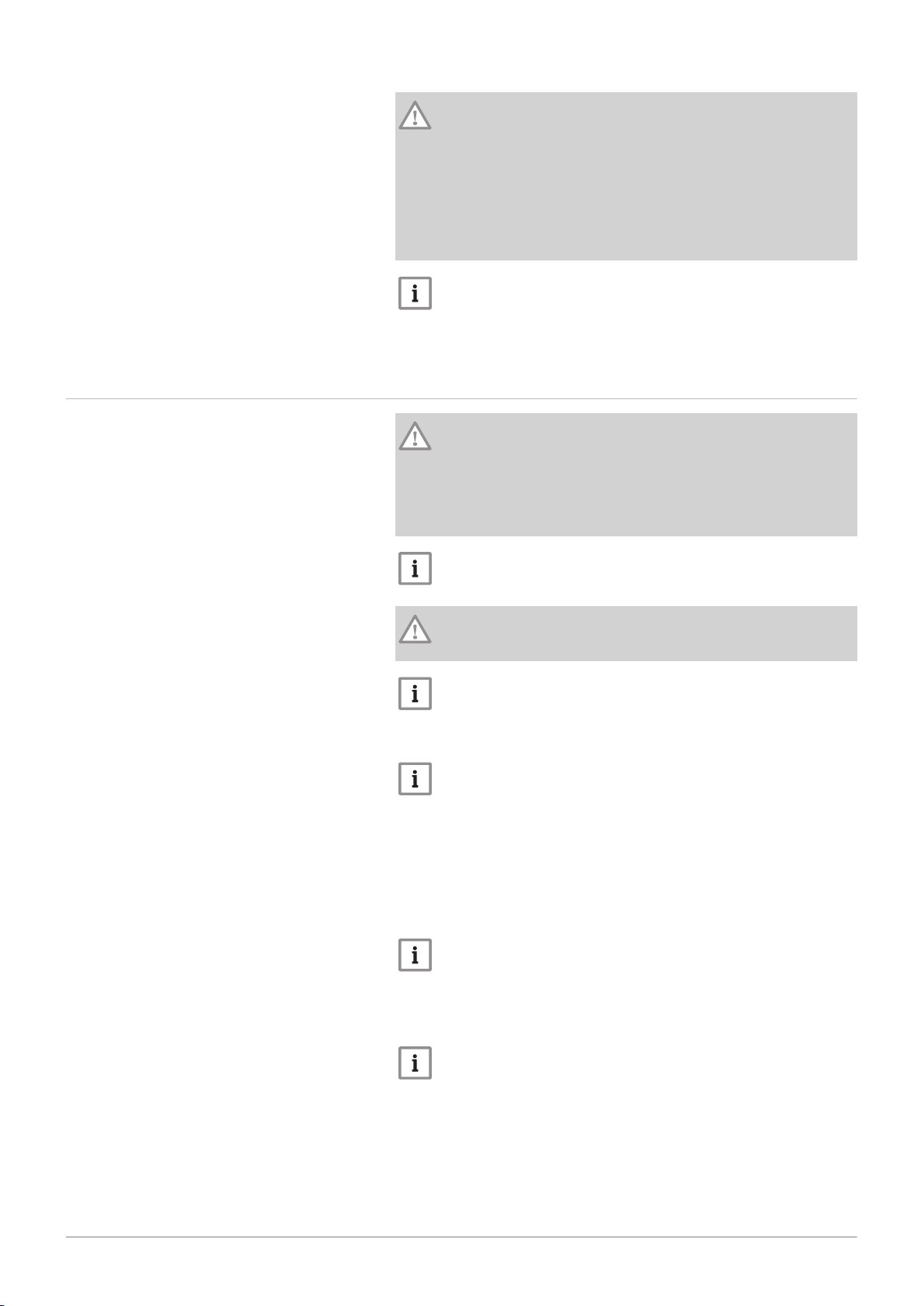
2.2 Symbols used on the appliance
Fig.1
Important
Please note: important information.
See
Reference to other manuals or pages in this manual.
1 Alternating current.
2 Protective earthing.
3 Before installing and commissioning the appliance, carefully read
the instruction manuals provided.
4 Dispose of used products through an appropriate recovery and
recycling structure.
5 Caution: danger of electric shock, live parts. Disconnect the mains
power prior to carrying out any work.
6 Connect the appliance to the protective earthing.
Page 11
3 Technical specifications
7718497 - v03 - 04012019 EFU-C S FF 11
3 Technical specifications
3.1 Homologations
3.1.1 Certifications
The boiler complies with current standards.
CE identification number: 0085CQ0002
3.1.2 Oil categories
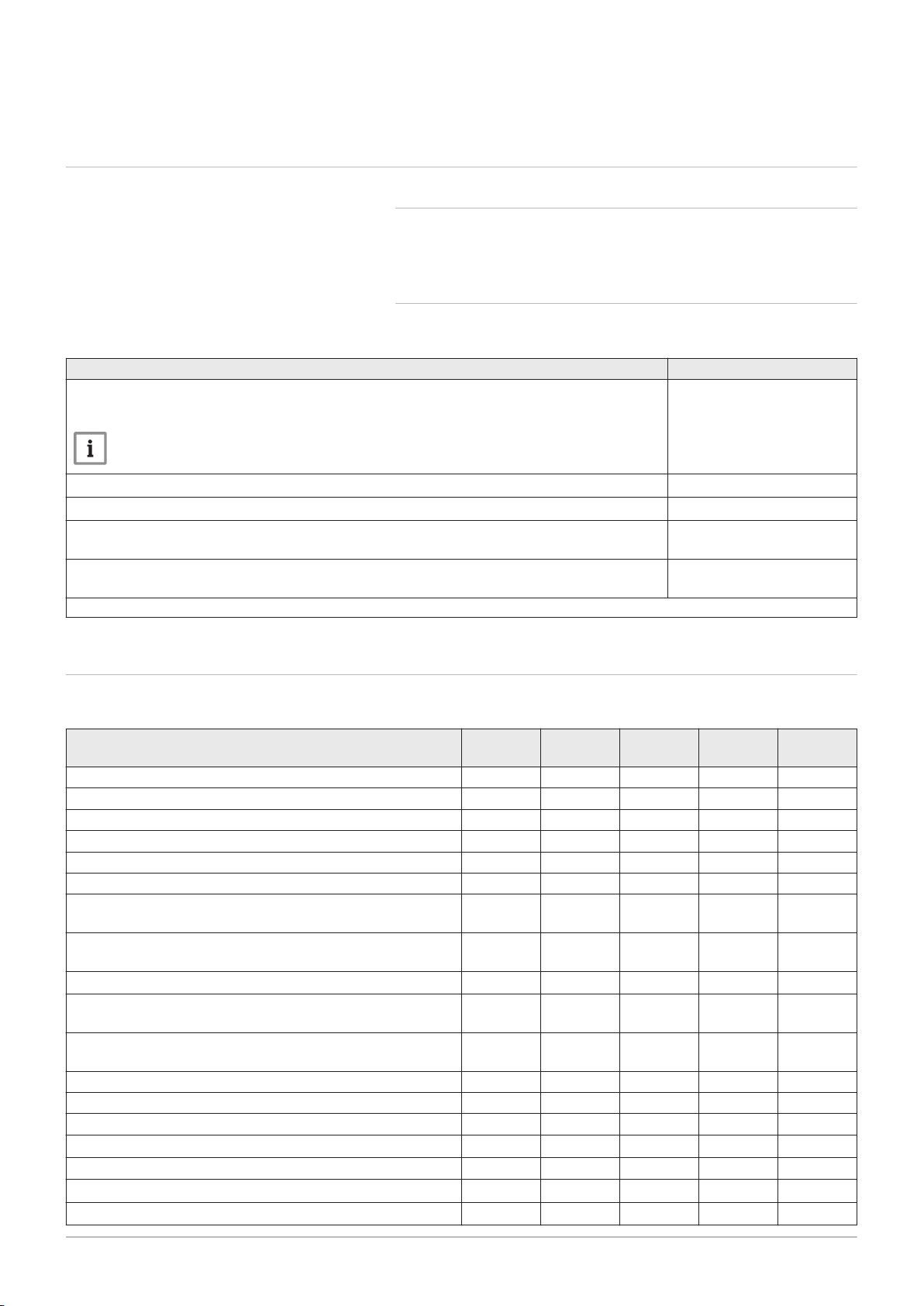
Tab.1
Type of oil that can be used Maximum viscosity
GNR
Non-road diesel with a maximum EMAG content of 7 %
(1)
Important
To be used exclusively for a boiler fitted with a burner with a heater.
6 mm2/s at 20 °C
Standard fuel oil
Low-sulphur oil
Bio-oil B10
Mixture of low-sulphur oil (<50 mg/kg) plus 5.9 to 10.9% (in volume) of EMAG
Bio-oil B5 (or Bio 5)
Mixture of low-sulphur oil (<50 mg/kg) plus 3 to 5.9% (in volume) of EMAG
(1) Liquid petroleum products — Fatty Acid Methyl Esters used as heating fuel
(1)
(1)
6 mm2/s at 20 °C
6 mm2/s at 20 °C
6 mm2/s at 20 °C
6 mm2/s at 20 °C
3.2 Technical data
Tab.2 Technical parameters for boiler space heaters
Product name EFU C–S
19 FF
Condensing boiler Yes Yes Yes
Low-temperature boiler
(1)
No No No
B1 boiler No No No
Cogeneration space heater No No No
Combination heater Yes Yes Yes
Rated heat output
Useful heat output at rated heat output and high tempera
ture regime
(2)
Useful heat output at 30% of rated heat output and low tem
perature regime
(1)
Seasonal space heating energy efficiency
Useful efficiency at rated heat output and high temperature
(2)
regime
Useful efficiency at 30% of rated heat output and low tem
perature regime
(1)
Prated
P
4
P
1
ƞ
s
ƞ
4
ƞ
1
kW 18 23 31
kW 18.3 23.1 30.7
kW 5.8 7.3 9.6
% 88 89 88
% 90.4 90.3 89.8
% 95.2 94.6 93.7
Auxiliary electricity consumption
Full load
Part load
Stand-by
elmax
elmin
P
SB
kW 0.194 0.154 0.156
kW 0.076 0.063 0.066
kW 0.004 0.004 0.004
Other specifications
Standby heat loss
Ignition burner power consumption
P
stby
P
ign
kW 0.084 0.084 0.100
kW - - -
EFU C–S
24 FF
EFU C–S
32 FF
Page 12

3 Technical specifications
12 EFU-C S FF 7718497 - v03 - 04012019
Product name EFU C–S
19 FF
Annual energy consumption
Sound power level, indoors
Emissions of nitrogen oxides NO
(1) Low temperature means for condensing boilers 30°C, for low temperature boilers 37°C and for other heaters 50°C return temperature
(at heater inlet).
(2) High temperature regime means 60 °C return temperature at heater inlet and 80 °C feed temperature at heater outlet.
Q
HE
L
WA
x
GJ 59 74 101
dB 60 60 60
mg/kWh 118 118 118
EFU C–S
24 FF
EFU C–S
32 FF
See
The back cover for contact details.
Page 13
4 Description of the product
MW-5000451-1
2
1
3
4
MW-5000031-3
7718497 - v03 - 04012019 EFU-C S FF 13
4.1 General description
4 Description of the product
Floor-standing condensing oil boilers from the EFU-C S FF range have the
following specifications:
Heating only with possibility to produce domestic hot water by combining
them with a domestic hot water tank
High-efficiency heating
Low polluting emissions
Heating body in cast iron
Condenser with ceramic pipes and stainless steel walls
Pre-assembled and pre-set oil burner
Electronic control panel
Flue gas discharge via a forced flue type connection
4.2
Main components
4.2.1
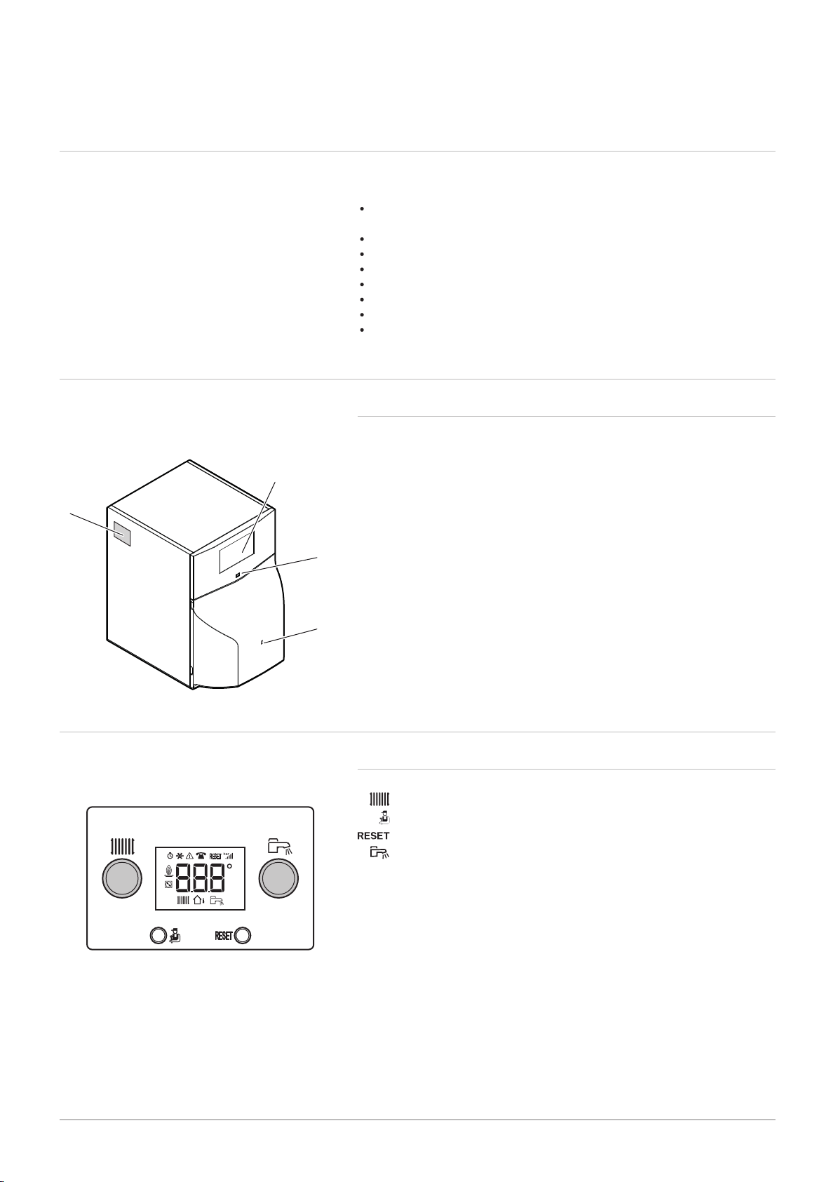
Fig.2
1
2
3 Access to the burner manual reset button
4
4.3 Description of the control panel B-Control
4.3.1 Description of the keys
Boiler
Control panel
On/Off switch
Data plate
Fig.3
Heating temperature setting button
Level access key: Information, Installer or Chimney Sweep
Manual reset key
Domestic hot water temperature setting button
Page 14
h
MW-3000235-3
MW-1000043-5
1 2 3 4
MW-1000085-4
MW-1000083-5
4 Description of the product
14 EFU-C S FF 7718497 - v03 - 04012019
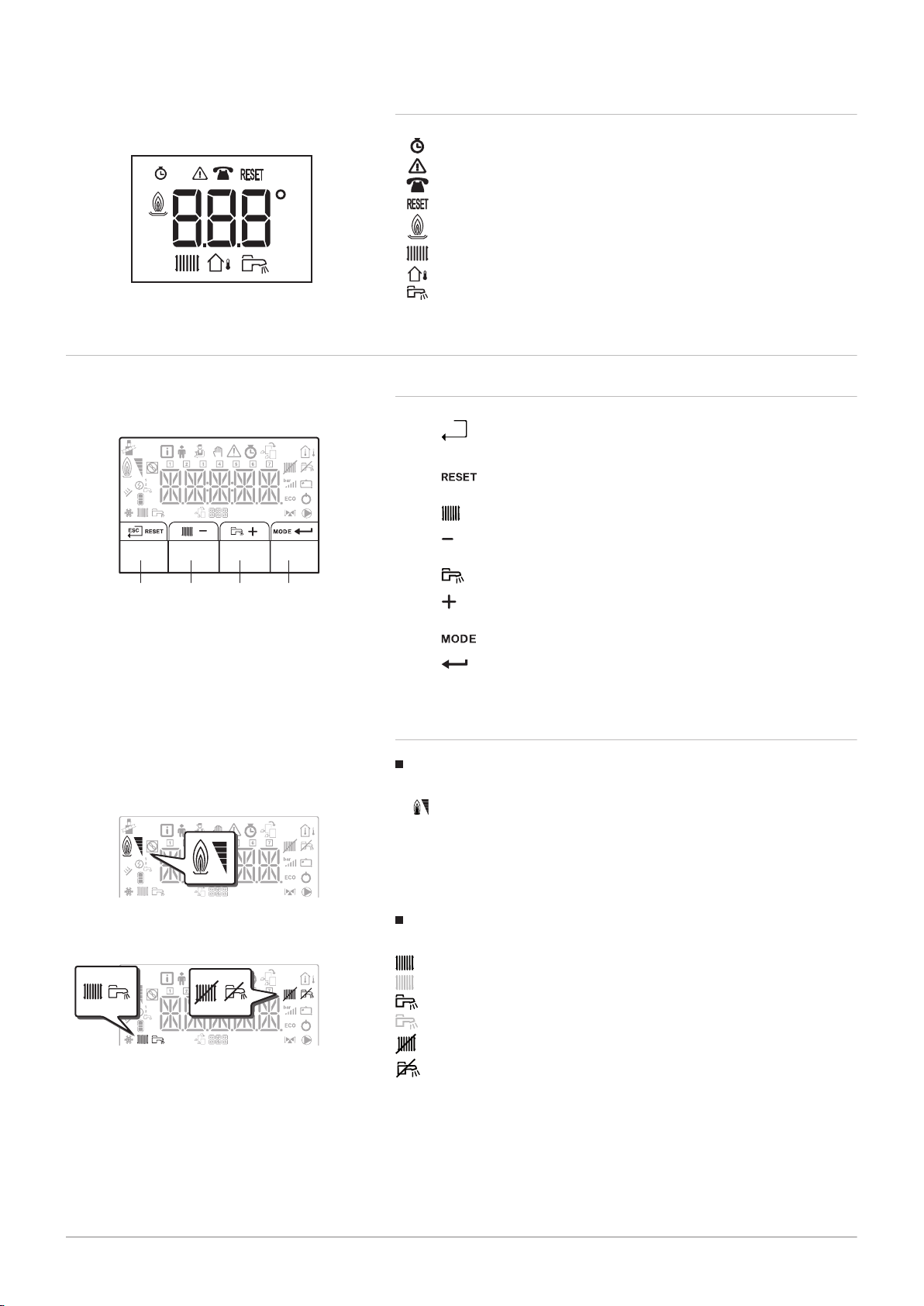
4.3.2 Description of the display
Fig.4
4.4
Fig.5
Description of the control panel IniControl 2
4.4.1 Description of the keys
1
2
3
Hour run meter
Malfunctions
Maintenance
Reset necessary
Burner status
Heating mode
Outside temperature sensor
Domestic hot water mode
: back to the previous level without saving the modifications
made
: manual reset
: accessing the heating parameters
: lowering the value
: accessing the domestic hot water parameters
: raising the value
Fig.6
Fig.7
4
: MODE display
: accessing the menu selected or confirming the value
modification
4.4.2 Description of the display
Burner Operation
Burner ON
Operating modes
Steady symbol: heating function enabled
Flashing symbol: heating production running
Steady symbol: domestic hot water function enabled
Flashing symbol: domestic hot water production running
Heating function disabled
Domestic hot water function disabled
Page 15
Menu display
MW-1000670-1
MW-1000683-2
...CUO / H04...
MW-1000687-1
...SCB / 04- / B...
MW-1000575-2
7718497 - v03 - 04012019 EFU-C S FF 15
4 Description of the product
Fig.8
Fig.9
Fig.10
Information menu: displays the measured values and the statuses
of the appliance
User menu: provides access to the User level setting parameters
Installer menu: provides access to the Installer level setting
parameters
Manual Forcing menu: the appliance runs at the set point
displayed, the pumps operate and the three-way valves are not
controlled.
Malfunction menu: the appliance has malfunctioned. This
information is signalled by an error code and a flashing display.
Sub-Menu COUNTERS
TIME PROG sub-menu: Timer programming dedicated to
heating and domestic hot water production
Sub-Menu CLOCK
PCB selection menu: access to information on the additional PCBs
connected
Display of PCB names
The name of the PCB for which the parameters are displayed is
shown as 3 characters.
CU-OH04 central unit PCB for the boiler
Fig.11
Fig.12
SCB-04B additional PCB: 2nd circuit
COUNTERS / TIME PROG / Sub-Menus CLOCK
COUNTERS sub-menu (CNT)
TIME PROG sub-menu: Timer programming dedicated to
heating and domestic hot water production (CIRC A, CIRC B,
ECS)
Timer program for Monday
Timer program for Tuesday
Timer program for Wednesday
Timer program for Thursday
Timer program for Friday
Timer program for Saturday
Timer program for Sunday
CLOCK sub-menu (CLK)
Page 16

MW-1001083-1
MW-5000038-4
4 Description of the product
16 EFU-C S FF 7718497 - v03 - 04012019
Temperature sensors
Fig.13
Fig.14
Outside temperature sensor connected:
fixed symbol for WINTER mode,
flashing symbol for SUMMER mode.
Other Information
Chimney Sweep Menu: forced operation in full load mode
Three-way valve connected
Three-way valve closed
Three-way valve open
Pump running
Page 17

5 Utilisation with the control panel B-Control
MW-1000668-1
MW-1000667-1
2’’
MW-1000668-1
7718497 - v03 - 04012019 EFU-C S FF 17
5.1 Browsing in the menus
Press any key to turn on the backlight for the control panel screen.
Important
If no key is pressed within 3 minutes, the control panel backlight
will go out.
The key is used to access the various menus:
Tab.3 Menus available
Information menu
Chimney Sweep menu
5 Utilisation with the control panel B-Control
Fig.15
Fig.16
Fig.17
5.2
Press the key to access the Information menu.
Press the key for 2 seconds to go back to the main display.
Press the key for 2 seconds to access the Chimney Sweep menu.
Press the key for 2 seconds to go back to the main display.
Keep pressing the key to scroll through the information.
Important
Information menu: 5 minutes after the key is pressed for the
last time, the display goes back to the main display.
Chimney Sweep menu: Thirty minutes after the key is
pressed for the last time, the display goes back to the main
display.
Start-up
If the boiler was powered off:
1. Check that the heating system and the boiler are adequately primed
with water. Recommended pressure between 0.15 and 0.2 MPa (1.5
and 2.0 bar).
2. Check that the storage tank is filled with fuel.
3. Open the oil inlet valve.
4. Switch on the boiler.
A venting cycle is run automatically.
The display shows the operating status of the boiler, the heating flow
temperature and any error codes.
Page 18

MW-3000241-3
MW-3000242-3
5 Utilisation with the control panel B-Control
18 EFU-C S FF 7718497 - v03 - 04012019
5.3 Shutdown
5.3.1 Switching off the heating
Fig.18
Fig.19
1. Turn the setting button all the way to the left until is
displayed.
Important
The frost protection function continues to run
5.3.2 Stopping domestic hot water production
1. Turn the setting button all the way to the left until is
displayed.
Important
Frost protection continues to run on the domestic hot water tank.
The venting cycle is not tripped when domestic hot water
production is shut down.
For more information, see
Setting the timer programming, page 31
5.3.3 Shutting down the installation
It is recommended that the boiler is kept powered on to ensure frost
protection.
5.4 Frost protection
Caution
The frost protection function does not work if the boiler is powered
off.
Caution
The integrated protection system only protects the boiler, not the
heating system.
Caution
Have the boiler and heating system drained by a qualified
professional if the home is left empty for a long period of time and
there is a chance of frost.
Important
To prevent the radiators and the installation from freezing in
places where that risk exists (e.g. in a garage or an equipment
room), we recommend the connection of an outside temperature
sensor to the boiler.
If the temperature of the water in the boiler falls too much, the integrated
protection device switches itself on. This device functions as follows:
If the water temperature is lower than 7°C, the circulation pump starts
up.
The water temperature is lower than 4°C, the boiler starts up and
switches off when the water temperature is above 35°C.
If the water temperature is higher than 10°C, the boiler shuts down and
the circulating pump continues to run for a short time.
Page 19

6 Utilisation with the control panel IniControl 2
MW-2000369-1
MW-1000576-2
MW-2000370-2
MW-2000371-1
7718497 - v03 - 04012019 EFU-C S FF 19
6.1 Browsing in the menus
Press any key to turn on the backlight for the control panel screen.
If no key is pressed within 3 minutes, the control panel backlight will go
out.
Fig.20
Press the 2 right-hand keys together to access the different menus:
Tab.4 Menus available
Information menu
User menu
Installer menu
Manual Forcing menu
Malfunction menu
COUNTERS sub-menu
TIME PROG sub-menu
CLOCK sub-menu
PCB selection menu
Important
The icon is displayed only if an optional PCB has
been installed.
6 Utilisation with the control panel IniControl 2
Fig.21
Fig.22
Fig.23
6.2
Important
The different menus are only accessible when the icons flash.
Press the key to:
access the next menu,
access the next sub-menu,
access the next parameter,
increase the value.
Press the key to:
access the previous menu,
access the previous sub-menu,
access the previous parameter
decrease the value.
Press the confirmation key to confirm:
a menu,
a sub-menu,
a parameter,
a value.
When the temperature is displayed, briefly pressing the back key h will
return to the time display.
Start-up
If the boiler was powered off:
1. Check that the heating system and the boiler are adequately primed
with water. Recommended pressure between 0.15 and 0.2 MPa (1.5
and 2.0 bar).
2. Check that the storage tank is filled with fuel.
3. Open the oil inlet valve.
4. Switch on the boiler.
A venting cycle is run automatically.
The display shows the operating status of the boiler, the heating flow
temperature and any error codes.
Page 20

MW-1001085-1
...CU- /-OH /-04...
MW-1001084-1
...SCb /-04 /-B...
MW-2000369-1
MW-5000137-2
6 Utilisation with the control panel IniControl 2
20 EFU-C S FF 7718497 - v03 - 04012019
6.2.1 Description of the PCBs
Fig.24
Fig.25
Fig.26
Management of a second circuit
When commissioning the boiler, the PCB displayed is the CU-OH04.
The primary circuit is managed by the CU-OH04 central unit PCB. The
name of the PCB is displayed on the screen: .
See
Boiler instructions for setting the boiler parameters
Only the installer can access the parameters and settings for each PCB.
In order to control an installation that has an additional circuit, it will be
necessary to install the SCB-04 PCB. The name of the PCB is displayed
on the screen: .
Important
Given that numerous settings can be made on the 2 PCBs,
depending on the circuit concerned, the name of the PCB will be
represented by in the rest of the manual.
6.2.2
Selecting a PCB
1. Access the menus by pressing the two keys on the right
simultaneously.
Fig.27
2. Access the PCB selection menu (only when several PCBs are
present).
Important
The PCB selection menu is available only when the icon
flashes.
3. Scroll through the names of the connected additional PCBs by
pressing the or keys.
The names of the installed PCBs will be displayed in sequence.
4. Confirm the required PCB by pressing the key.
Important
The flow temperature for the selected PCB is displayed by default,
as well as the status of the pump(s) and the status of the valve
connected to the selected PCB.
5. Go back to the main display by pressing the h key.
For more information, see
Modifying the User parameters, page 30
User menu, page 26
COUNTERS /TIME PROG / CLOCK menus, page 28
Page 21

6.3 Shutdown
MW-5000027-4
MW-5000133-3
MW-5000134-3
7718497 - v03 - 04012019 EFU-C S FF 21
6 Utilisation with the control panel IniControl 2
6.3.1 Switching off the heating
Important
Heating mode can be managed via the TIME PROG sub-menu
dedicated to timer programming.
Fig.28
Fig.29
Fig.30
1. Go to stop mode by pressing the key.
2. Select the heating mode by pressing the key.
3. Confirm by pressing the key.
4. Select the heating shut-down pressing the key.
The screen displays: .
The frost protection function continues to run.
The heating has been shut down.
Important
Press the key to restart the appliance: the screen will
display .
5. Confirm by pressing the key.
6. Go back to the main display by pressing the h key.
Important
The display disappears after a few seconds of inactivity.
For more information, see
Setting the timer programming, page 31
Page 22

MW-5000135-3
MW-5000136-3
MW-5000028-4
6 Utilisation with the control panel IniControl 2
22 EFU-C S FF 7718497 - v03 - 04012019
6.3.2 Stopping domestic hot water production
Important
Domestic hot water production can be managed via the TIME
PROG sub-menu dedicated to timer programming.
Fig.31
Fig.32
Fig.33
1. Go to stop mode by pressing the key.
2. Select domestic hot water production mode pressing the key.
3. Confirm by pressing the key.
4. Select domestic hot water production shut-down by pressing the
key.
The screen displays: .
The frost protection function continues to run.
Production of domestic hot water has been shut down.
6.4
Important
Press the key to restart the appliance: the screen will
display .
5. Confirm by pressing the key.
6. Go back to the main display by pressing the h key.
Important
The display disappears after a few seconds of inactivity.
6.3.3 Shutting down the installation
It is recommended that the boiler is kept powered on to ensure frost
protection.
Frost protection
Caution
The frost protection function does not work if the boiler is powered
off.
Caution
The integrated protection system only protects the boiler, not the
heating system.
Caution
Have the boiler and heating system drained by a qualified
professional if the home is left empty for a long period of time and
there is a chance of frost.
Page 23

6 Utilisation with the control panel IniControl 2
7718497 - v03 - 04012019 EFU-C S FF 23
Important
To prevent the radiators and the installation from freezing in
places where that risk exists (e.g. in a garage or an equipment
room), we recommend the connection of an outside temperature
sensor to the boiler.
If the temperature of the water in the boiler falls too much, the integrated
protection device switches itself on. This device functions as follows:
If the water temperature is lower than 7°C, the circulation pump starts
up.
The water temperature is lower than 4°C, the boiler starts up and
switches off when the water temperature is above 35°C.
If the water temperature is higher than 10°C, the boiler shuts down and
the circulating pump continues to run for a short time.
Page 24

MW-3000243-3
7 Control panel settings B-Control
24 EFU-C S FF 7718497 - v03 - 04012019
7 Control panel settings B-Control
7.1 List of parameters
7.1.1 Information menu
Tab.5 Information list
Information Description Display
°C
°C
°C
Heating water temperature (°C)
Domestic hot water temperature (°C)
Outdoor temperature (°C)
Burner status 0 = burner off
Energy meter on the heating water circuit
Energy meter on the domestic hot water circuit
Not available
The symbol flashes
The symbol flashes
If no domestic hot water sensor connected: dis
play — — —
The symbol flashes.
100 = burner on
The symbol and the value flash
The value in kW ( ) is displayed alternate
ly with the value in MW (
Example: for 12560 kW, will display al
ternating with
The symbol and the value flash
The value in kW ( ) is displayed alternate
ly with the value in MW (
Example: for 12560 kW, will display al
ternating with
).
).
7.2 Setting the parameters
Fig.34
For more information, see
Browsing in the menus, page 17
7.2.1
No temperature sensor connected Outside temperature sensor con
Set the heating water temperature
setpoint
1. Set the temperature setpoint or room temperature depending on the
Setting the heating water temperature
nected
Set the required room temperature
configuration described above by turning the setting button .
Important
If the heating water temperature setpoint is lower than 16°C and if
no outside temperature sensor is connected, the heating cuts out
automatically.
Important
This setting is possible regardless of the display.
Page 25

MW-3000244-3
MW-3000246-3
MW-3000245-3
7 Control panel settings B-Control
7718497 - v03 - 04012019 EFU-C S FF 25
Fig.35
Fig.36
Fig.37
2. Go back to the main display by pressing the key for two seconds.
Important
After five seconds without pressing any keys on the control panel,
the display goes back to the main display.
7.2.2 Modifying the domestic hot water temperature setpoint
1. Set the domestic hot water temperature setpoint by turning the setting
button .
2. Go back to the main display by pressing the key for two seconds.
Important
After five seconds without pressing any keys on the control panel,
the display goes back to the main display.
Page 26

1
2
MW-2000435-1
3
2
8 Control panel settings IniControl 2
26 EFU-C S FF 7718497 - v03 - 04012019
8 Control panel settings IniControl 2
8.1 List of parameters
8.1.1 User menu
Fig.38
1 Sub-menu available
2 Name of the PCB or circuit
Tab.6
Sub-menu Description Name of the PCB or circuit
Tab.7
Parameter Description CU-OH04 factory
CP010 Heating water flow temperature set point for the heated zone if no
CP080 Activity zone 1 temperature set point
CP081 Activity zone 2 temperature set point
CP082 Activity zone 3 temperature set point
CP083 Activity zone 4 temperature set point
CP084 Activity zone 5 temperature set point
CP085 Activity zone 6 temperature set point
CP140 Reduced cooling set point
CP141 Comfort cooling set point
CP142 Set point cooling activity zone 3
List of User sub-menus
Main heating circuit
Additional heating circuit B
Domestic hot water circuit
CU-OH04 central unit PCB
Additional PCB for circuit B
HMI control panel
Important
CP : Circuits Parameters = Heating circuit parameters
List of parameters in the / sub-menus of the User menu
outside temperature sensor has been connected.
For the CU-OH04 PCB: Can be set from 7 to 90°C
For the SCB-04B PCB: Can be set from 7 to 100°C
Can be set from 5 to 30°C
Can be set from 5 to 30°C
Can be set from 5 to 30°C
Can be set from 5 to 30°C
Can be set from 5 to 30°C
Can be set from 5 to 30°C
Can be set from 20 to 30°C
Can be set from 20 to 30°C
Can be set from 20 to 30°C
3 Setting parameters
75°C 50°C
16°C 16°C
20°C 20°C
6°C 6°C
21°C 21°C
22 °C 22 °C
20°C 20°C
not available 30°C
not available 25°C
not available 25°C
setting
Factory setting
SCB-04B
Page 27

8 Control panel settings IniControl 2
7718497 - v03 - 04012019 EFU-C S FF 27
Parameter Description CU-OH04 factory
Factory setting
setting
CP143 Set point cooling activity zone 4
not available 25°C
Can be set from 20 to 30°C
CP144 Set point cooling activity zone 5
not available 25°C
Can be set from 20 to 30°C
CP145 Set point cooling activity zone 6
not available 25°C
Can be set from 20 to 30°C
CP200 Room temperature set point in forced mode
20°C 20°C
Can be set from 5 to 30°C
CP320 Circuit operating mode:
0 0
= timer programming
= manual mode
= frost protection mode
CP350 Do not modify this setting. not available 55°C
CP360 Do not modify this setting. not available 10°C
CP510 Circuit temporary room temperature set point
20°C 20°C
Can be set from 5 to 30°C
CP540 Temperature set point for SWIMMING POOL mode
not available 20°C
Can be set from 0 to 39°C.
CP550 Chimney zone
0 0
= off
= on
CP570 Do not modify this setting. 0 0
CP660 Select the icon to display this zone on the room sensor:
3 3
SCB-04B
= none
= all
= bedroom
= living room
= office
= outside
= kitchen
= basement
Important
DP : Direct Hot Water Parameters = Domestic hot water tank
parameters
Tab.8
List of parameters in the sub-menu of the User menu
Parameter Description CU-OH04 factory
setting
DP060 Number of timer programs selected for domestic hot water production mode
0
Can be set from 0 to 2
DP070 Domestic hot water temperature set point in comfort mode
55°C
Can be set from 40 to 65°C.
DP080 Domestic hot water temperature set point in reduced mode
10°C
Can be set from 10 to 60°C.
DP200 Domestic hot water production mode:
0
= timer programming
= manual mode
= frost protection mode
DP337 Water temperature set point in the domestic hot water tank in holiday mode
10°C
Can be set from 10 to 60°C.
Page 28

8 Control panel settings IniControl 2
28 EFU-C S FF 7718497 - v03 - 04012019
Important
AP : Appliance Parameters = Appliance parameters
Tab.9
List of parameters in the / sub-menus of the User menu
Parameter Description CU-OH04 factory
setting
AP016 Central heating operation:
1 not available
= off (no heating or cooling)
= on
AP017 Domestic hot water tank operation:
1 not available
= off
= on
AP073 SUMMER / WINTER set point switch:
22°C only accessible
Can be set from 15 to 30°C
set to 30.5°C = function deactivated
AP074 SUMMER override:
0 0
= off
= on
AP082
Changing the summer/winter timer :
1 not available
= off
= on
For more information, see
Browsing in the menus, page 19
Selecting a PCB, page 20
Factory setting
SCB-04B
to the installer
Tab.10
List of sub-menus
Sub-menu Description
COUNTERS
(1)
(1)
Timer programming for the main heating circuit
Timer programming for the additional heating circuit B
Timer programming for the domestic hot water circuit
Setting the clock and the date
(1) This menu is not displayed if a room sensor is connected.
8.1.2 COUNTERS /TIME PROG / CLOCK menus
For more information, see
Browsing in the menus, page 19
Selecting a PCB, page 20
Page 29

COUNTERS sub-menu
7718497 - v03 - 04012019 EFU-C S FF 29
8 Control panel settings IniControl 2
Tab.11
Choices available in the sub-menu: names of associated PCBs (only when several PCBs are present)
Sub-menu PCB Parameter
CU-OH04 central unit PCB
Additional PCB for circuit B
Parameter Description Unit CU-OH04 PCB SCB-04B PCB
AC001 Number of hours' operation hours X X
AC005 Consumption in heating mode kWh X
AC006 Consumption in domestic hot water production
Wh X
mode
AC026 Number of hours' pump operation hours X
AC027 Number of pump start-ups - X
CC001 Number of hours' pump operation hours X
CC010 Number of pump start-ups hours X
DC002 Number of reversal valve cycles - X
DC003 Number of hours' reversal valve operation hours X
DC004 Number of burner start-ups in domestic hot water
- X
production mode
DC005 Number of hours of burner operation in domestic
hours X
hot water production mode
PC002 Number of burner start-ups - X
PC003 Number of hours of burner operation hours X
PC004 Number of safety lock-downs (E36) - X
AC002 Number of hours' burner operation since the last
hours X
service
AC003 Number of hours' operation since the last service hours X
AC004 Number of burner start-ups since the last service - X
SERVICE Resetting the maintenance service
- X
: hour run meters , ,
are reset.
Tab.12
List of parameters in the sub-menu of the menu
Parameter Unit
HOURS Can be set from 0 to 23 available
MINUTE Can be set from 0 to 59 available
DATE Can be set from 1 to 31 available
MONTH Can be set from 1 to 12 available
YEAR Can be set from 2000 to 2100 available
Page 30

MW-5000008-2
MW-5000040-6
MW-5000144-3
MW-3000249-4
8 Control panel settings IniControl 2
30 EFU-C S FF 7718497 - v03 - 04012019
8.2 Setting the parameters
8.2.1 Modifying the User parameters
Caution
Altering the factory settings may impair operation of the appliance.
Fig.39
Fig.40
1. Go to the User menu.
2. Select the desired sub-menu by pressing the or key.
3. Confirm the selection by pressing the key.
4. Select the required parameter by pressing the or keys to scroll
through the list of adjustable parameters.
5. Confirm the selection by pressing the key.
6. Modify the value of the parameter using the or keys.
7. Confirm the new value of the parameter by pressing the key.
8. Go back to the main display by pressing the h key.
For more information, see
Browsing in the menus, page 19
Selecting a PCB, page 20
8.2.2 Setting the heating
Caution
Altering the factory settings may impair operation of the appliance.
Important
The heating mode can be managed using the TIME PROG menu.
Fig.41
Fig.42
1. Access the heating parameters by pressing the key.
2. Select the desired circuit, if there are several PCBs, by pressing the
or key.
3. Confirm the selection by pressing the key.
The status of the heating and the associated heating water
temperature set point are displayed alternately.
4. Select the mode to be modified by pressing the or key:
4.1. ON mode = comfort
4.2. ECO mode = reduction
5. Modify the heating water temperature set point for the selected mode
by pressing the or key.
Important
Press the h key to cancel all input.
6. Confirm the new temperature set point by pressing the key.
7. Go back to the main display by pressing the h key.
For more information, see
Setting the timer programming, page 31
Page 31

MW-6000254-2
MW-5000044-4
MW-5000139-4
MW-1000594-3
8 Control panel settings IniControl 2
7718497 - v03 - 04012019 EFU-C S FF 31
8.2.3 Setting the domestic hot water temperature
Important
Domestic hot water production can be managed via the TIME
PROG sub-menu dedicated to timer programming.
Fig.43
Fig.44
Fig.45
1. Access the domestic hot water production parameters by pressing the
key.
2. Modify the domestic hot water temperature set point by pressing the
or key.
Important
Press the h key to cancel all input.
3. Confirm the new temperature set point by pressing the key.
Go back to the main display by pressing the h key.
For more information, see
Setting the timer programming, page 31
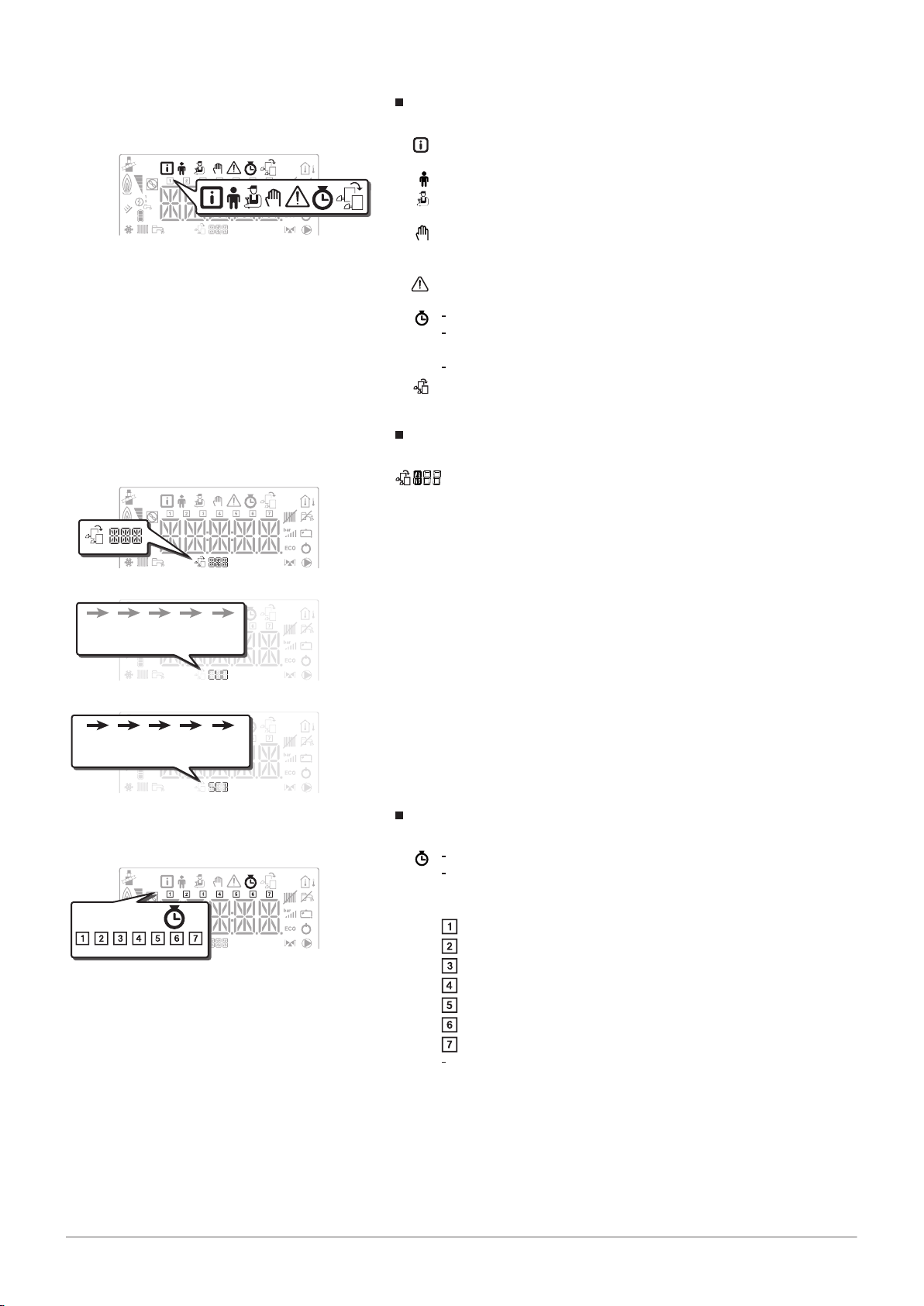
8.2.4 Setting the timer programming
1. Access the COUNTERS/ TIME PROG / CLOCK menus.
Important
When using a programmable room thermostat, this menu is not
displayed.
2. Select the desired circuit by pressing the or key.
3. Confirm the selection by pressing the key.
The icons dedicated to the days of the week all flash at the same
time: .
Fig.46
4. Select the desired day number by pressing the or key until the
icon dedicated to the desired day flashes.
Day selected Description
, , , , , , every day of the week
Monday
Tuesday
Wednesday
Thursday
Friday
Saturday
Sunday
Important
The key is used to move to the right.
The key is used to move to the left.
5. Confirm the selection by pressing the key.
Page 32

MW-5000142-2
MW-5000143-3
MW-5000010-4
MW-5000042-4
8 Control panel settings IniControl 2
32 EFU-C S FF 7718497 - v03 - 04012019
Fig.47
Fig.48
6. Set the start time for the period by pressing the or key.
Confirm the selection by pressing the key.
7.
8. Select the status that corresponds to the period by pressing
the or key.
Status
to for periods
Description
to
comfort mode
reduced mode
9. Confirm the selection by pressing the key.
10. Repeat steps 8 to 11 to define the comfort periods to and
the associated status to .
Important
No setting: 10 minutes
The setting determines the end.
Times
06:00-22:00 06:00 22:00
06:00-08:00
06:00 08:00 11:30 13:30
11:30-13:30
06:00-08:00
06:00 08:00 11:30 14:00 17:30 22:00
11:30-14:00
17:30-22:00
Fig.49
Fig.50
11. Go back to the main display by pressing the h key.
Example:
8.2.5 Activating Manual Forcing for heating
The Manual Forcing menu is only used with the heating mode.
Access the Manual Forcing menu.
1.
2. Set the value of the heating water temperature set point by pressing
the or key.
3. Confirm the new value of the heating water temperature set point by
pressing the key.
4. Go back to the main display by pressing the h key.
Important
To force domestic hot water production, select the
parameter available in the User menu.
Page 33

8.3 Reading out measured values
7718497 - v03 - 04012019 EFU-C S FF 33
8 Control panel settings IniControl 2
The measured values are available in the Information menu of the
different PCBs.
Certain parameters are displayed:
according to certain system configurations,
according to the options, circuits or sensors actually connected.
Tab.13
Sub-menu Description
Tab.14
Sub-menu Description
Tab.15
Parameter Description Unit CU-OH04
AM010 Pump rotation speed % X
AM012 Control system sequence: Status
AM014 Control system sequence: Sub-Status
List of sub-menus
CU-OH04 central unit PCB
List of sub-menus for an installation with an additional PCB
Values available (X) in sub-menus , ,
Important
See following table
HMI control panel
CU-OH04 central unit PCB
SCB-04B additional PCB
HMI control panel
PCB
X X
X X
SCB-04B PCB
Important
See following table
AM016 Heating circuit flow temperature °C X
AM018 Heating circuit return temperature °C X
AM019 Heating circuit hydraulic pressure, in the heating system bar X
AM027 Outdoor temperature °C X
AM051 Generator relative output % X
AM091 Seasonal mode active (Summer/Winter) X X
AM101 Temperature set point X
CM030 Room temperature measured °C X X
CM040 Circuit flow temperature °C X
CM060 Pump speed % X
CM120 Circuit operating mode:
= AUTO
= manual
= frost protection
= temporary
CM130 Current activity status:
= frost protection
= reduced
= comfort
= anti-legionella
CM190 Desired room temperature set point °C X X
X X
X X
Page 34

8 Control panel settings IniControl 2
34 EFU-C S FF 7718497 - v03 - 04012019
Parameter Description Unit CU-OH04
SCB-04B PCB
PCB
CM210 Temperature outside the zone X X
DM001 Domestic hot water tank temperature °C X X
PM002 Heating temperature set point °C X
FXX.XX Software version for the selected PCB X X
PXX.XX Parameter version for the selected PCB X X
8.3.1 Control system sequence
Tab.16 List of statuses and sub-statuses
Status (parameter
= rest = system on standby
= heat demand (boiler start-up) = anti-short cycle activated
= burner start-up = opening of the flue gas valve / oil valve (not available)
= boiler in heating mode = nominal internal set point
= boiler in domestic hot water production
mode
= burner shut-down = burner off
= end of heat demand (boiler shut-down) = boiler pump post-operation time delay or domestic hot water back-up
= off = awaiting burner start-up
= blockage = blockage code XX
) Sub-status (parameter )
= open isolating valve (not available)
= boiler pump or domestic hot water start-up
= opening of the flue damper
= burner start-up
= pre-ignition
= limited internal set point
= normal output check
= temperature stabilisation time
= nominal internal set point
= limited internal set point
= normal output check
= temperature stabilisation time
= closure of the shut-off damper
= closure of the flue damper
start-up time delay
= boiler pump or domestic hot water stopped
= close isolating valve
= start anti-short cycle
= anti-short cycle activated
Page 35

9 Maintenance
7718497 - v03 - 04012019 EFU-C S FF 35
9.1 General
9 Maintenance
We recommend having the boiler inspected and serviced at regular
intervals.
Caution
Do not neglect to service the boiler. Contact a qualified
professional or take out a maintenance contract for the obligatory
annual servicing of the boiler.
Failure to service the appliance voids the warranty.
Danger of electric shock
Before service work is started, the boiler has to be de-energised
and secured from accidentally being switched back on.
Caution
Have an inspection carried out and the flues swept at least once a
year or more, depending on the regulations in force in your
country.
Caution
Only qualified professionals are authorised to carry out
maintenance work on the boiler and the heating system.
9.2 Maintenance instructions
Caution
After maintenance or repair work, check the entire heating system
to ensure that there are no leaks.
Caution
Only genuine spare parts may be used.
9.2.1 Check the hydraulic pressure
1. Checking the hydraulic pressure in the installation.
2. If the hydraulic pressure is less than 0.08 MPa (0.8 bar), top up the
level of water in the heating installation so that the hydraulic pressure
is between 0.15 and 0.2 MPa (1.5 and 2.0 bar).
3. Carry out a visual check for any water leaks.
9.2.2
1. Open the valves on all radiators connected to the heating system.
2. Set the room thermostat to as low a temperature as possible.
3. Put the boiler in shut-down/frost protection mode.
4. Open the fill valve.
5. Close the filling valve when the pressure gauge shows a pressure of
6. Put the boiler in heating mode.
7. When the pump has stopped, vent again and top up the water
Topping up the installation with water
0.15 MPa (1.5 bar).
pressure.
Important
Filling and venting the installation twice a year should be sufficient
to obtain an adequate hydraulic pressure. If it is often necessary
to top up the installation with water, contact your installer.
Page 36

AD-3000484-B
87
A
C
B
6
5
4
3
2
1
2
3
4
1
11
9 Maintenance
36 EFU-C S FF 7718497 - v03 - 04012019
9.3 Venting the system
Fig.51 Venting the system
Any air in the boiler, the pipes or the valves must be removed in order to
prevent unwanted noises that may occur during heating or when tapping
water. To do this, proceed as follows:
1. Open the valves of all the radiators connected to the system.
2. Set the room thermostat to the highest possible temperature.
3. Wait until the radiators are warm.
4. Switch off the boiler.
5. Wait approximately 10 minutes, until the radiators feel cold.
6. Vent the radiators. Work from the lowest to the highest.
7. Open the venting valve with the bleed key, keeping a cloth pressed
against the vent.
Warning
The water may still be hot.
8. Wait until water comes out of the venting valve and then close the
venting valve.
9. Turn on the boiler.
A 3-minute venting cycle is performed automatically.
10. After venting, check that the water pressure in the system is still
adequate. If necessary, top up the water level in the heating system
11. Adjust the room thermostat or temperature control.
Page 37

10 Troubleshooting
MW-3000240-4
MW-6000210-4
MW-5000061-3
MW-5000060-3
MW-2000369-1
7718497 - v03 - 04012019 EFU-C S FF 37
10.1 Error messages B-Control
Fig.52
10 Troubleshooting
10.1.1 Error code display
If an error is detected, the error code is displayed automatically.
Important
The reset is automatic.
Fig.53
10.2
Fig.54
Fig.55
Error messages IniControl 2
10.1.2
Fault code display
If a fault is detected, the fault code is displayed automatically.
Important
The and icons flash.
Reset by pressing the button.
10.2.1 Error messages
Resetting the control panel allows the appliance to be restarted.
The message appears when a fault code is detected. After resolving
the problem, pressing the key resets the appliance's functions and
thus eradicates the fault.
If several faults occur, they are displayed one after the other.
1. Reset the control panel by pressing the key for 3 seconds,
when an error message is displayed.
In economy mode, the appliance will not run a domestic hot water
heating cycle after a central heating cycle.
2. Display the current operating status by briefly pressing the key.
10.2.2 Accessing the error memory
The error and fault codes are listed together in the memory.
Fig.56
1. Access the menus by pressing the two keys on the right
simultaneously.
Page 38

MW-5000011-3
MW-1000689-1
MW-1000690-1
10 Troubleshooting
38 EFU-C S FF 7718497 - v03 - 04012019
Fig.57
Fig.58
Fig.59
2. Select the Malfunction menu by pressing the key.
3. Select the PCB by pressing the or key. The icon appears.
Confirm the PCB selection by pressing the
key: the PCB name
appears.
Important
The Er:xxx parameter flashes. 000 corresponds to the number of
stored errors.
4. Go to the error details by pressing the key.
5. Scroll through the errors by pressing the or key. When this menu
opens, the row of the error in the memory appears briefly. The PCB
name appears. Go back to the error list by pressing the h key.
Important
The errors are stored from the most recent to the oldest.
6. Go back to the Er:xxx display by pressing the h key. Press the
key: the CLR parameter flashes after the errors. 000 corresponds to
the PCB selected.
Clear the error memory by pressing the key.
7. Exit the Malfunctions menu by pressing the h key.
Page 39

11 Environmental
MW-3000179-03
7718497 - v03 - 04012019 EFU-C S FF 39
11.1 Disposal and Recycling
Fig.60
11 Environmental
Recycling
Warning
Removal and disposal of the boiler must be carried out by a
qualified installer in accordance with local and national
regulations.
11.2
Energy savings
Energy-saving advice:
Do not block ventilation outlets.
Do not cover the radiators. Do not hang curtains in front of the radiators.
Install reflective panels behind the radiators to prevent heat losses.
Insulate the pipes in rooms that are not heated (cellars and lofts).
Close the radiators in rooms not in use.
Do not run hot (or cold) water pointlessly.
Install an energy-saving shower head, which can save up to 40 %
energy.
Take showers rather than baths. A bath consumes twice as much water
and energy.
Page 40

12 Warranty
40 EFU-C S FF 7718497 - v03 - 04012019
12 Warranty
12.1 General
We would like to thank you for buying one of our appliances and for your
trust in our product.
In order to ensure continued safe and efficient operation, we recommend
that the product is regularly inspected and maintained.
Your installer and our service department can assist with this.
12.2
Terms of warranty
The following provisions do not affect the application, in favour of the
buyer, of the legal provisions with regard to hidden defects that are
applicable in the buyer's country.
This appliance comes with a warranty that covers all manufacturing faults;
the warranty period will commence on the date of purchase stated on the
installer's invoice.
The warranty period is stated in our price list.
As a manufacturer, we can by no means be held liable if the appliance is
used incorrectly, is poorly maintained or not maintained at all, or is not
installed correctly (it is your responsibility to ensure that installation is
carried out by a qualified installer).
In particular, we cannot be held liable for material damage, intangible
losses or physical injury resulting from an installation that does not comply
with:
Legal or regulatory requirements or provisions laid down by the local
authorities.
National or local regulations and special provisions relating to the
installation.
Our manuals and installation instructions, in particular in terms of regular
maintenance of the appliances.
Our warranty is limited to the replacement or repair of the parts found to
be defective by our technical services team, excluding labour, transfer and
transport costs.
Our warranty does not cover replacement or repair costs for parts that may
become defective due to normal wear, incorrect usage, the intervention of
unqualified third parties, inadequate or insufficient supervision or
maintenance, a mains supply that is not appropriate or the use of
unsuitable or poor quality fuel.
Smaller parts, such as motors, pumps, electrical valves etc., are
guaranteed only if these parts have never been dismantled.
The rights established in European Directive 99/44/EEC, implemented by
legal decree No. 24 of 2 February 2002 and published in Official Journal
No. 57 of 8 March 2002, remain in force.
Page 41

13 Appendix
BBB
7718497 - v03 - 04012019 EFU-C S FF 41
13.1 Product fiche
Tab.17 Product fiche for boiler space heaters
EFU C–S
19 FF
Seasonal space heating energy efficiency class
EFU C–S
24 FF
13 Appendix
EFU C–S
32 FF
Rated heat output
Seasonal space heating energy efficiency % 88 89 88
Annual energy consumption GJ 59 74 101
Sound power level LWA indoors dB 60 60 60
13.2
Tab.18 Product fiche for the Temperature controls
B-Control
Class III
Contribution to space heating energy efficiency % 1.5
13.3
Tab.19 Product data sheet for the Temperature controls
IniControl 2
Class III
Contribution to space heating energy efficiency % 1.5
Product fiche - Temperature Controls
Product data sheet - Temperature controls
(Prated or Psup)
kW 18 23 31
See
For specific precautions on assembly, installation and
maintenance: see the chapter on Safety Instructions.
Page 42

AD-3000743-01
%
1
‘I’
2
%+
3
%( - ‘I’ ) x 0.1 = ±
4
%(‘III’ x + ‘IV’ x ) x 0.9 x ( /100) x = +
(1)
A* = 0.95, A = 0.91,
B = 0.86, C = 0.83,
D - G = 0.81
5
%( - ‘I’ ) x ‘II’ = +
6
%0.5 x 0.5 x = -
54
<30%
G F E D C B A A
+
A
++
A
+++
%+ (50 x ‘II’) =
7
7
%
from fi che of solar device
Solar contribution AND Supplementary heat pump
Solar contribution
The energy effi ciency of the package of products provided for in this fi che may not correspond to its actual energy effi ciency once installed
in a building, as this effi ciency is infl uenced by further factors such as heat loss in the distribution system and the dimensioning of the
products in relation to building size and characteristics.
Boiler and supplementary heat pump installed with low temperature heat emitters at 35°C ?
Seasonal space heating energy effi ciency class of package
Seasonal space heating energy effi ciency of package
OR
Seasonal space heating energy effi ciency (in %)
Supplementary heat pump
Tank rating
Collector effi ciency (in
%)
Tank volume (in m³) Collector size (in m²)
Seasonal space heating energy effi ciency (in %)
Supplementary boiler
Class I = 1%, Class II = 2%, Class III = 1.5%,
Class IV = 2%, Class V = 3%, Class VI = 4%,
Class VII = 3.5%, Class VIII = 5%
Temperature control
Seasonal space heating energy effi ciency of boiler
(1) If tank rating is above A, use 0.95
select smaller value
from fi che of heat pump
from fi che of heat pump
from fi che of boiler
from fi che of temperature control
13 Appendix
42 EFU-C S FF 7718497 - v03 - 04012019
13.4 Product fiche
Fig.61 The boiler's product fiche indicates the space heating energy efficiency of the product.
Page 43

I The value of the seasonal space heating energy efficiency of the
7718497 - v03 - 04012019 EFU-C S FF 43
preferential space heater, expressed in %.
II The factor for weighting the heat output of preferential and
supplementary heaters of a package as set out in the following
table.
III The value of the mathematical expression: 294/(11 · Prated),
whereby "Prated" is related to the preferential space heater.
IV The value of the mathematical expression 115/(11 · Prated),
whereby "Prated" is related to the preferential space heater.
Tab.20 Weighting of boilers
Psup / (Prated + Psup)
(1)(2)
II, package without hot water storage tank II, package with hot water storage tank
0 0 0
0.1 0.3 0.37
0.2 0.55 0.70
0.3 0.75 0.85
0.4 0.85 0.94
0.5 0.95 0.98
0.6 0.98 1.00
≥ 0.7 1.00 1.00
(1) The intermediate values are calculated by linear interpolation between the two adjacent values.
(2) Prated is related to the preferential space heater or combination heater.
13 Appendix
Tab.21 Package efficiency
EFU C–S
19 FF
Seasonal energy efficiency of the package for space heating combined with
% 90 91 90
IniControl 2
Seasonal energy efficiency of the package for space heating combined with B-
% 90 91 90
Control
EFU C–S
24 FF
EFU C–S
32 FF
Page 44

13 Appendix
44 EFU-C S FF 7718497 - v03 - 04012019
Page 45

13 Appendix
7718497 - v03 - 04012019 EFU-C S FF 45
Page 46

13 Appendix
46 EFU-C S FF 7718497 - v03 - 04012019
Page 47

© Copyright
All technical and technological information contained in these technical instructions, as well as any drawings and technical
descriptions supplied, remain our property and shall not be multiplied without our prior consent in writing. Subject to alterations.
Page 48

DE DIETRICH
FRANCE
NEUBERG S.A.
LU
DE DIETRICH SERVICE
AT
DE DIETRICH
CN
www.dedietrich-thermique.fr
www.neuberg.lu
www.dedietrich-heating.com
www.dedietrich-heating.com
www.dedietrich-heiztechnik.com
SERVICE CONSOMMATEURS
0 825 120 520
0,15 €
/ min
03 88 80 27 00
03 88 80 27 99
+352 (0)2 401 401
0800 / 201608 freecall
+86 (0)106 581 4017
+86 (0)106 581 4018
+86 (0)106 581 7056
+86 (0)106 581 4019
contactBJ@dedietrich.com.cn
Direction de la Marque
57, rue de la Gare - F-67580 Mertzwiller
VAN MARCKE
BE
www.vanmarcke.be
+32 (0)56/23 75 11
Weggevoerdenlaan 5
B- 8500 KORTRIJK
39 rue Jacques Stas - B.P.12
L- 2549 LUXEMBOURG
Room 512, Tower A, Kelun Building
12A Guanghua Rd, Chaoyang District
C-100020 BEIJING
DE DIETRICH THERMIQUE
I
beria S.L.U
ES
www.dedietrich-calefaccion.es
+34 935 475 850
info@dedietrich-calefaccion.es
C/Salvador Espriu, 11
08908 L’HOSPITALET de LLOBREGAT
BDR THERMEA C
zech Republic s.r.o
CZ
DE DIETRICH
Technika Grzewcza sp. z o.o.
PL
www.dedietrich.cz
www.facebook.com/DeDietrichPL
www.dedietrich.pl
+420 271 001 627
dedietrich@bdrthermea.cz
+48 71 71 27 400
biuro@dedietrich.pl
MEIER TOBLER AG
CH
www.meiertobler.ch
+41 (0) 44 806 41 41
info@meiertobler.ch
Bahnstrasse 24 - CH - 8603 SCHWERZENBACH
Serviceline
+41 (0)8 00 846 846
MEIER TOBLER SA
CH
www.meiertobler.ch
+41 (0) 21 943 02 22
info@meiertobler.ch
Chemin de la Veyre-d'En-Haut B6,
CH -1806 St-Légier-La-Chiésaz
Jeseniova 2770/56 - 130 00 Praha 3
ul. Północna 15-19, 54-105 Wrocław
Serviceline
+41 (0)8 00 846 846
000 «БДP T Pyc»
RU
www.dedietrich.ru
8 800 333-17-18
info@dedietrich.ru
129164, Россия, г. Москва
Зубарев переулок, д. 15 /1
Бизнес-центр «Чайка Плаза»,офис 309
DUEDI S.r.
l
IT
www.duediclima.it
+39 0171 85717 0
+39 0171 687875
info@duediclima.it
Distributore Uffi ciale Esclusivo
De Dietrich-Thermique Italia Via Passatore, 12
12010 San Defendente di Cervasca CUNEO
801 080 881
Infocentrala
7718497 - v03 - 04012019
7718497-001-03
 Loading...