

Page 1

9
EN
CONTENTS
1 / SAFETY INSTRUCTIONS
• Important warnings __________________________________________ 10
2 / INSTALLING YOUR DISHWASHER
• Free-standing appliances ____________________________________ 11
• Built-in appliances __________________________________________ 11
• Appliances built-in under a hob ________________________________ 12
• Levelling by adjusting the feet ________________________________ 12
• Installing the sound-proofing flap ______________________________ 12
• Connecting to the water supply ________________________________ 13
• Draining away the waste water ________________________________ 14
• Connecting to the electricity supply ____________________________ 15
Important :
Please read this instructions manual carefully so that you can comply with the ins-
tructions for installing and fitting your machine.
NB :
This instructions manual covers various models. There may be some slight differen-
ces between your appliance and the descriptions shown.
Page 2

10
EN
1 / SAFETY INSTRUCTIONS
• IMPORTANT WARNINGS
Important :
After unpacking your appliance, make sure that it has not suffered any damage during
transport. Never connect up a damaged appliance. If your appliance is damaged, please contact
your dealer.
Danger :
If your appliance operates incorrectly, disconnect it (pull out the plug) or switch off the
circuit concerned and close the water supply tap. Contact our After-Sales Service.
Important :
All the necessary electrical and plumbing work for installing the appliance must respectively be carried out by a qualified electrician or plumber.
— Once you have installed your appliance, ensure that it is not resting on the power cable or the
water supply or drain hoses.
— The appliance must be kept disconnected from the mains supply throughout the whole installation process.
— Check that your appliance’s Earth circuit complies with the prevailing regulations.
— The electrical connection details on the manufacturer’s plate on your machine must match
those for the mains power supply.
Important :
For safety’s sake, do not leave your dishwasher’s door fully open after use.
If your dishwasher is being installed on a carpeted floor, ensure that the feet are set to leave
an air space under the appliance.
Page 3
11
EN
2 / INSTALLING YOUR DISHWASHER
Fig. 04
Fig. 03
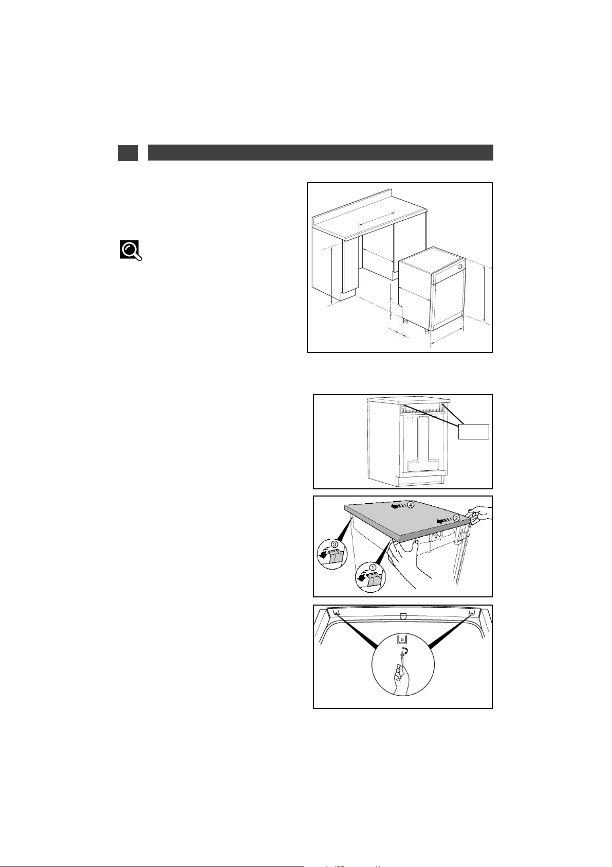
You can use the top of the appliance as a
worktop.
NB:
Do not position your dishwasher too
close to a heat source; otherwise the trim
around the top could be damaged.
•
BUILT-IN APPLIANCES
•
FREE-STANDING APPLIANCES
•
Installation dimensions
By removing the appliance’s worktop you can
build in your appliance under an existing
worktop provided that the space conforms to
the dimensions on the sketch. (Fig. 01)
•
Building in your appliance under
a worktop
If you are building in your appliance under an
existing worktop:
— Remove the top of the appliance by unscrewing the two screws under the edge of the
top (Fig. 02).
— Remove the top by unclipping it from the
back of the appliance and pushing it a few cm
to move it (Fig. 03).
— Lift the top of your dishwasher to release it
(Fig. 03).
— Insert the dishwasher into its appropriate
space
— Adjust the height of the feet, if necessary
(please refer to the Section: “Levelling by
adjusting the feet”).
— Fasten your dishwasher to the kitchen worktop with two screws under the front of the
plastic lip (Fig 04).
If your worktop is marble or a similar material,
you can fasten your dishwasher at the side
with two brackets (available from After-Sales
or your dealer).
You can also incorporate your appliance into
a vertical unit (raised above the ground).
Fig. 02
Screw
820 - 830
820 min
110 mn
50
595
600
570 min
570
Fig. 01
Page 4

12
EN
Fig. 06
2 / INSTALLING YOUR DISHWASHER
Danger :
If your worktop has a hob fitted above your dishwasher, you must fit thermal insulation
on top of your dishwasher. You can obtain an insulation panel from your dealer. Remember to
leave a space between the gas pipe and the top of your dishwasher.
• LEVELLING BY ADJUSTING THE FEET
• INSTALLING THE
SOUND-PROOFING FLAP
Ensure that your dishwasher is quite plumb
and stable and that it i9n the place where it
will be installed. The feet are adjustable. Use a
screwdriver to adjust them, if necessary, so
that the door closes and seals perfectly
(Fig.06).
Ensure that the dishwasher’s door closes correctly, without catching at the sides.
To improve the appliance’s sound-proofing,
fit the flap supplied with your dishwasher
(depending on the model):
① - Tilt your dishwasher backwards slightly
so that you can clip the sound-proofing flap to
the base of the plinth and ensure it is well clipped at three points (the ends and the centre),
② - Adjust the flap’s height by cutting off one
or more strips manually after scoring the end
with a pair of scissors.
The flap must be in contact with the floor.
(Fig. 07).
①
②
Fig. 07
• APPLIANCES BUILT-IN UNDER A HOB
To improve the built-in appliance’s soundproofing, fit the sound-proofing seals (depending on the model). ( on Fig. 05)
If the recess is bigger, stick on seal using
the adhesives provided.
1
21
•
SOUND-PROOFING SEALS
1
2
Fig. 05
Page 5

13
EN
2 / INSTALLING YOUR DISHWASHER
• CONNECTING TO THE WATER SUPPLY
Fig. 08
Danger :
The symbol indicates that the hose
is fitted with an electrical device for cutting
off the water supply (depending on the
model). Do not leave this hose in water and
do not cut it.
NB:
Any connection to a water conduit
necessarily involves the risk of a leak occurring, whatever the precautions taken.
Therefore, always close the water tap when
you are not using your machine.
This dishwasher can be supplied with cold
water or hot water up to a maximum of 60°C.
When supplying with hot water, check that
your original hose allows such connection
(red marking on the hose). However, we
recommend that you connect to the cold
water supply. Your appliance is fitted with a
supply hose 1.50m long.
Connect the hose to a tap with a threaded
end, diameter 20/27 (3/4" BSP).
Check that the water pressure does not
exceed the values below:
Flow rate: 10 L/min (1 L/min minimum)
Pressure: 1 to 10 bars (0.1 - 1 MPa) (Fig. 08)
If the water pressure is too high, please fit a
pressure regulator. Your Water department
will advise you of the water pressure in your
region.
Warning :
If you use a self-piercing tap, check
that there is sufficient water flow.
Check that the hose seal is present and that
the connection is tight. (Fig. 05)
Do not re-use any previously used hoses for
making the connection.
Avoid any kinks or constrictions in the hose,
which could prevent the water from passing or
slow down its flow, particularly when building
in the appliance under the worktop. (Fig. 9).
If the appliance is connected to new pipes or
pipes that have not been used for a certain
length of time, let the water run for a few minutes before connecting the water hose to avoid
and deposits of sand or rust that could block
the water hose’s filter.
00..11-- 11 MMPPaa
11--1100 bbaarr
1100LL//mmiinn
Fig. 09
Page 6

14
EN
2 / INSTALLING YOUR DISHWASHER
• DRAINING AWAY THE WASTE WATER
Fig. 11
Fig. 12
You can connect the end of the drain hose to:
- A ventilated U-bend (Fig. 10) or
- A sink U-bend (Fig. 10) or
- The edge of the sink, using the special plastic
hook provided (depending on the model) (Fig. 12).
When connecting to a U-bend, you must remove
the flapper from the U-bend. Then fully install the
rubber end. If necessary, add a tightening collar
(Fig. 11).
NB :
Ensure that the drain hose is held in
place with a tie to avoid any potential flooding.
The drain connection must be 0.40m (minimum)
to 1m (maximum) above the floor (Fig. 10).
If necessary, you can increase the hose’s length
(up to 3m maximum). In this case, check that the
appliance drains correctly. The hose must rest
on the floor and only rise vertically close to the
drainage system.
For appliances installed in vertical units, the
drainage system must not rise higher than the
top of the appliance.
Important :
When fitting the hose, pull on it gradually
so as not to kink it. (Fig. 9)
Avoid any kinks or constrictions in the hose,
which could prevent the water from passing or
slow down its flow.
15 cm
maxi
,
,
4
,
Fig. 10
Page 7

15
EN
2 / INSTALLING YOUR DISHWASHER
The appliance must be at a standstill when
connecting to the electricity supply circuit.
Before connecting your appliance, ensure
that:
- The mains voltage indicated on the manufacturer’s plate on your machine (230V) matches
the voltage supplied by your installation.
- Your meter and the fuses can support the
current. A 16A fuse is the minimum requirement.
If you must connect your appliance to a different voltage from that indicated on your
machine, connect an appropriate transformer.
NB :
Use the services of a qualified electrician to make the modifications and ensure
that your electrical installation complies with
the regulations.
This appliance must necessarily be connected directly to an earthed plug and socket.
In all cases, it must be connected in accordance with the prevailing regulations in the
country concerned and any additional regulations from the local electricity utility.
Warning :
The plug and socket must be accessible even after your appliance has been installed. The appliance must not be connected
via an extension lead, a multiple socket or an
electric time delay programmer. (Fig. 13)
We cannot be held responsible in the event
of an accident or an incident caused by the
lack of or a defective earthing system.
Your dishwasher complies with European
Directives 73/23/EEC (Low Voltage Directive)
and 89/336/EEC (Electromagnetic Compatibility)
as modified by Directive 93/68/EEC.
•
Replacing the power cable
Danger :
For your safety’s sake, this operation
must only be performed by the manufacturer’s After-Sales Department or by someone
with similar qualifications in order to avoid
any risks.
•
Appliances delivered without a plug
Danger :
The wires in your appliance’s power
cable are coloured as follows:
- Green & Yellow Earth
- Blue Neutral
- Brown Live
If the cable’s colours do not match your plug,
proceed as follows:
The wire coloured green and yellow must be
connected to the connector in your plug marked with the letter E, the symbol or coloured green and yellow.
The blue-coloured wire must be connected to
the connector marked with the letter N or
coloured black.
The brown-coloured wire must be connected
to the connector marked with the letter L or
coloured red.
Fig. 13
• ELECTRICAL CONNECTION
 Loading...