

Page 1
FR GUIDE D’UTILISATION SV BRUKSANVISNING
DE BETRIEBSANLEITUNG
EN GUIDE TO INSTALLATION
ES MANUAL DE UTILICIÓN
IT MANUALE D’USO
NL GEBRUIKSAANWIJZING
PT GUIA DE UTILIZAÇÂO
CS PŘÍRUČKA K POUŽITÍ
PL INSTRUCJA OBSŁUGI
HU HASZNÁLATI UTASÍTÁS
EL ΕΓΧΕΙΡΙΔΙΟ ΧΡΗΣΗΣ
DA BRUGERMANUAL
SK PRÍRUČKA NA POUŽITIE
Hotte décor Digestoř
Dekor-Dunstabzugshaube Wyposażenie okapu
Decorative Hood Szagelszívó berendezés
Campana extractora decorativa Διακοσμητικός Απορροφητήρας
Cappa arredamento Indretnings emhætte
Designafzuigkap Digestor
Exaustor decorativo Spiskåpa för innebruk
DHD789X
Page 2
F
Le symbole sur le produit ou son emballage indique que ce produit ne peut être traité
comme déchet ménager. Il doit plutôt être remis au point de ramassage concerné, se chargeant
du recyclage du matériel électrique et électronique. En vous assurant que ce produit est éliminé
correctement, vous favorisez la prévention des conséquences négatives pour l’environnement et
la santé humaine qui, sinon, seraient le résultat d’un traitement inapproprié des déchets de ce
produit. Pour obtenir plus de détails sur le recyclage de ce produit, veuillez prendre contact avec
le bureau municipal de votre région, votre service d’élimination des déchets ménagers ou le magasin où vous avez acheté le produit. Cet appareil est commercialisé en accord avec la directive
européenne 00/96/CE sur les dèchets del équipments èlectriques et èlctroniques (WEEE).
DE
Das Symbol auf dem Produkt oder seiner Verpackung weist darauf hin, dass dieses
Produkt nicht als normaler Haushaltsabfall zu behandeln ist, sondern an einem Sammelpunkt
für das Recycling von elektrischen und elektronischen Geräten abgegeben werden muss. Durch
Ihren Beitrag zum korrekten Entsorgen dieses Produkts schützen Sie die Umwelt und die Gesundheit Ihrer Mitmenschen. Umwelt und Gesundheit werden durch falsches Entsorgen gefährdet. Weitere Informationen über das Recycling dieses Produkts erhalten Sie von Ihrem Rathaus,
Ihrer Müllabfuhr oder dem Geschäft, in dem Sie das Produkt gekauft haben. Dieses Elektrohaushaltsgerät ist entsprechend der EU-Richtlinie 00/96/CE Über Elektro- und Elektronik
– Altgeräte (WEEE).
EN
The symbol on the product or on its packaging indicates that this product may not
be treated as household waste. Instead it shall be handed over to the applicable collection point
for the recycling of electrical and electronic equipment. By ensuring this product is disposed of
correctly, you will help prevent potential negative consequences for the environment and human health, which could otherwise be caused by inappropriate waste handling of this product.
For more detailed information about recycling of this product, please contact your local city office, your household waste disposal service or the shop where you purchased the product. This
appliance is marked according to the European directive 00/96/EC on waste electrical and
electronic equipment (WEEE).
ES
El símbolo en el producto o en su embalaje indica que este producto no se puede
tratar como desperdicios normales del hogar. Este producto se debe entregar al punto de recolección de equipos eléctricos y electrónicos para reciclaje. Al asegurarse de que este producto se deseche correctamente, usted ayudará a evitar posibles consecuencias negativas para el
ambiente y la salud pública, lo cual podría ocurrir si este producto no se manipula de forma
adecuada. Para obtener información más detallada sobre el reciclaje de este producto, póngase
en contacto con la administración de su ciudad, con su servicio de desechos del hogar o con la
tienda donde compró el producto. Este electrodomestico està marcado conforme a la directiva
Europea 000/96/CE sobre los residuos de aparatos elèctricos y electrònicos (WEEE).
IT
Il simbolo sul prodotto o sulla confezione indica che il prodotto non deve essere considerato come un normale rifiuto domestico, ma deve essere portato nel punto di raccolta appropriato per il riciclaggio di apparecchiature elettriche ed elettroniche. Provvedendo a smaltire
questo prodotto in modo appropriato, si contribuisce a evitare potenziali conseguenze negative
per l’ambiente e per la salute, che potrebbero derivare da uno smaltimento inadeguato del
prodotto. Per informazioni più dettagliate sul riciclaggio di questo prodotto, contattare l’ufficio
comunale, il servizio locale di smaltimento rifiuti o il negozio in cui è stato acquistato il prodotto. Questo elettrodomestico è marcato conformemente alla Direttiva Europea 00/96/CE sui
rifiuti da apparecchiature elettriche ed elettroniche (WEEE).
Page 3
NL
Het symbool op het product of op de verpakking wijst erop dat dit product niet als
huishoudafval mag worden behandeld. Het moet echter naar een plaats worden gebracht waar
elektrische en elektronische apparatuur wordt gerecycled. Als u ervoor zorgt dat dit product op
de correcte manier wordt verwijderd, voorkomt u mogelijk voor mens en milieu negatieve gevolgen die zich zouden kunnen voordoen in geval van verkeerde afvalbehandeling
Voor meer details in verband met het recyclen van dit product, neemt u het best contact op
met de gemeentelijke instanties, het bedrijf of de dienst belast met de verwijdering van huishoudafval of de winkel waar u het product hebt gekocht. Dit apparrat voldoet aan de Europese
richtlijnen
PT
reciclagem dos mesmos e contribua, assim, para a protecção do ambiente, depositando-os nos
contento-res municipais previstos para este efeito. O seu aparelho contém também inúmeros
materiais recicláveis. Por esta razão, está marcado com este símbolo a fim de lhe indicar que os
aparelhos usados não devem ser mis-turados com os restantes resíduos. A reciclagem dos aparelhos organizada pelo fabricante será, pois, efectuada nas melhores condições, de acordo com
directiva europeia 00/96/CE sobre os resíduos de equipamentos eléctricos e electrónicos.
a
Dirija-se à câmara municipal da sua residência ou ao seu revendedor para conhecer os pontos
de recolha de aparelhos usados, localizados mais perto da sua residên-cia.
CS
normální domácí odpad, ale musí být odevzdaný do sběrného střediska tříděného odpadu pro
elektronická a elektrotechnická zařízení. Adekvátní tříděný sběr výrobků napomáhá chránit před
negativním dopadem na životní prostředí a lidské zdraví, ke kterému by mohlo dojít v případě nevhodného zpracování výrobku. Podrobnější informace o zpracování tohoto výrobku si
vyžádejte u odpovědného místního úřadu, místní organizace odpovědně za zpracování odpadu
nebo v obchodě, kde byl výrobek zakoupen. Tento výrobek je označen v souladu s evropskou
směrnicí 00/96/ES o elektrickém a elektronickém odpadu (RAEE).
00/96/CE voor elektrische en elektronische afval (WEEE).
Os materiais de embalagem deste aparelho são recicláveis. Por isso, participe na
Symbol na výrobku nebo na obalu znamená, že výrobek nesmí být považován za
.
PL
Symbol umieszczony na produkcie lub jego opakowaniu wskazuje, że wyrób nie powinien
być traktowany jako normalny odpad gospodarstwa domowego i przy likwidacji należy go przekazać
do stosownego punktu zbiorki recyklingu wyposażenia elektrycznego i elektronicznego.
Dbając o właściwą likwidację zużytych wyrobów przyczyniasz się do ochrony środowiska naturalnego i zapobiegasz potencjalnemu zagrożeniu zdrowia, jakie może stwarzać nieodpowiednie postępowanie z likwidowanym sprzętem gospodarstwa domowego. Szczegółowe informacje odnośnie
postępowania, odzysku i recyklingu niniejszego wyrobu można uzyskać w od władz lokalnych, służb
odpowiedzialnych za usuwanie odpadów lub w sklepie, w którym kupiłeś ten wyrób. To urządzenie
jest oznaczone odpowiednim symbolem zgodnie z dyrektywą europejską 00/96/CE odnośnie
postępowania z odpadkami urządzeń elektrycznych i elektronicznych.
UN
A terméken, vagy a csomagoláson feltüntetett jel mutatja, hogy a terméket nem szabad
hétköznapi háztartási hulladékként kezelni, hanem egy elektromos és elektronikus berendezések
újrahasznosítására alkalmas gyűjtőhelyre kell szállítani. A hulladék megfelelő módon történő eltávolításával nagyobb eséllyel kerülhető el az olyan esetleges negatív hatás a környezetre vagy az
egészségre, ami a hulladék nem megfelelő kezeléséből adódhat.
Amennyiben további információra van szüksége a termék újrahasznosításával kapcsolatban, lépjen
kapcsolatba a községi/városi hivatallal, a helyi hulladék begyűjtő szolgáltatóval, vagy az üzlettel
ahol a terméket vásárolta. Ez a háztartási készülék a 00/96/CE, elektromos és elektronikus készülékek hulladékairól szóló Európai Irányelvnek (WEEE) megfelelően van jelölve.
Page 4
EL
Το σύμβολο στο προϊόν ή στη συσκευασία δείχνει ότι το προϊόν δεν πρέπει να θεωρηθεί σαν κανονικό οικιακό απόρριμμα, αλλά πρέπει να παραδοθεί στο κατάλληλο σημείο
περισυλλογής για την ανακύκλωση ηλεκτρικών και ηλεκτρονικών συσκευών.
Φροντίζοντας να διαθέσετε αυτό το προϊόν με κατάλληλο τρόπο, συμβάλλετε στην αποφυγή πιθανών αρνητικών συνεπειών για το περιβάλλον και την υγεία, που θα μπορούσαν να
προκύψουν από μια ακατάλληλη διάθεση του προϊόντος. Για πιο λεπτομερείς πληροφορίες
για την ανακύκλωση του παρόντος προϊόντος, ελάτε σε επαφή με τις δημοτικές υπηρεσίες,
την τοπική υπηρεσία διάθεσης απορριμμάτων ή το κατάστημα στο οποίο αποκτήσατε το
προϊόν. Η παρούσα ηλεκτρική συσκευή έχει σημανθεί σύμφωνα με την Ευρωπαϊκή Οδη-
00/96/CE σχετικά με τα απορρίμματα από τις ηλεκτρικές και ηλεκτρονικές συσκευές
γία
(WEEE).
DA
Symbolet på produktet eller konfektionen indikerer at produktet ikke bør anses som
normalt husholdningsaffald, men i stedet skal det bringes til et sted der har med genbrug af
elektriske og elektroniske apparater at gøre. Ved bortskaffelse af dette produkt på passende
måde, undgår man at udøve negative konsekvenser for miljøet og sundheden, der eventuelt
kunne forårsages af en upassende bortskaffelse af produktet. For mere detaljeret information
omkring genbrug af dette produkt, bedes man kontakte kommunekontoret, den lokale service
for bortskaffelse af affald eller forhandleren hvor apparatet er købt. Dette husholdningsapparat
er mærket i overensstemmelse med Europa Direktivet 00/96/CE om bortskaffelse af elektriske og elektroniske apparater.
SK
Symbol na výrobku alebo na obale znamená, že výrobok nesmie byť považovaný za
normálny domáci odpad, ale musí byť odovzdaný do zberného strediska triedeného odpadu pre
elektronické a elektrotechnické zariadenie. Adekvátny triedený zber výrobkov napomáha chrániť životné prostredie a ľudské zdravie pred jeho negatívnym dopadom, ku ktorému by mohlo
dojsť v prípade nevhodného spracovania výrobku. Podrobnejšie informácie o spracovaní tohto
výrobku si vyžiadajte u zodpovedného miestneho úradu, miestnej organizácie zodpovednej za
spracovanie odpadu alebo v obchode, kde bol výrobok zakúpený. Tento výrobok je označený v
súlade s európskou smernicou 00/96/ES o elektrickom a elektronickom odpade (OEEZ).
SV
Symbolen på produkten eller på emballaget betyder att produkten inte får betraktas
som normalt hushållsavfall, utan den måste föras till en sopstation för återvinning av elektriska
och elektroniska apparater. Om produkten avyttras på rätt sätt, kan man undvika eventuella negativa konsekvenser för miljö och hälsa, som annars skulle kunna resultera av en felaktig avyttring av produkten. För mera detaljerad information angående avyttring av produkten kontakta
kommunalkontoret, sopstationen eller affären, där produkten inköpts. Denna hushållsprodukt
är markerad enligt EU-direktivet 00/96/EN beträffande återvinning av elektriska och elektroniska apparater (WEEE).
Page 5
FR
www.dedietrich-electromenager.com
DE
EN
ES
IT
NL
PT
CS
PL
HU
EL
16
6
6
6
66
76
86
96
106
Chère Cliente, Cher Client,
6
Vous venez d’acquérir une hotte DE DIETRICH et nous vous en remercions.
Nos équipes de recherche ont conçu pour vous cette nouvelle génération
d’appareils, qui par leur qualité, leur esthétique, leurs fonctions et leurs
6
évolutions technologiques en font des produits d’exception, révélateurs de
notre savoir-faire.
Votre nouvelle hotte DE DIETRICH s’intègrera harmonieusement dans votre
cuisine et alliera parfaitement les performances d’aspiration, et la facilité
d’utilisation. Nous avons voulu vous offrir un produit d’excellence.
Vous trouverez également dans la gamme des produits DE DIETRICH, un
vaste choix de fours, de fours à micro-ondes, de tables de cuisson, de lavevaisselle, et de réfrigérateurs intégrables, que vous pourrez coordonner à
votre nouvelle hotte DE DIETRICH.
Bien entendu, dans un souci permanent de satisfaire le mieux possible vos
exigences vis à vis de nos produits, notre service consommateurs est à
votre disposition et à votre écoute pour répondre à toutes vos questions ou
suggestions (coordonnées à la fin de ce livret).
116
DA
1
SK
SV
16
Dans le souci d’une amélioration constante de nos produits, nous nous réservons le
droit d’apporter à leurs caractéristiques techniques, fonctionnelles ou esthétiques
toutes modifications liées à leur évolution.
Important : Avant de mettre votre appareil en marche, veuillez lire attentivement ce guide d’installation et d’utilisation afin de vous familiariser plus
rapidement avec son fonctionnement.
Et connectez-vous aussi sur notre site
où vous trouverez nos dernières innovations ainsi que des informations
utiles et complémentaires.
6
www.dedietrich-electromenager. com
Les nouveaux objets de valeur
DE DIETRICH
Page 6

SOMMAIRE
1/ A L’ATTENTION DE L’UTILISATEUR
- Consignes de sécurité 7
- Description de votre appareil 8
2 / COMMENT INSTALLER VOTRE HOTTE
- Montage de votre hotte 9
- Installation 9
- Raccordement de votre hotte 10
3 / COMMENT FONCTIONNE VOTRE HOTTE 11
4 / COMMENT NETTOYER VOTRE HOTTE 12
5 / ANOMALIES DE FONCTIONNEMENT
- Comment changer la lampe 1
6 / SERVICE APRES-VENTE 14
FR
6
Page 7
1/ A L’ATTENTION DE L’UTILISATEUR
Important: Conservez cette notice d’utilisation avec votre appareil. Si l’appareil devait être
vendu ou cédé à une autre personne, assurez-vous que la notice d’utilisation l’accompagne.
Merci de prendre connaissance de ces conseils avant d’installer et d’utiliser votre appareil. Ils
ont été rédigés pour votre sécurité et celle d’autrui.
Le constructeur décline toute responsabilité pour tous les inconvénients, dommages ou incendies provoqués sur et par l’appareil et dus à la non observation des instructions de la présente
notice.
FR
- CONSIGNES DE SÉCURITÉ
Cet appareil a été conçu pour être utilisé par des particuliers dans leur lieu d’habitation. Cet
appareil doit être utilisé par des adultes. Veillez à ce que les enfants n’y touchent pas et ne
l’utilisent pas comme un jouet. Assurez-vous qu’ils ne manipulent pas les commandes de
l’appareil.
- A la réception de l’appareil, déballez-le ou faites le déballer immédiatement. Vérifiez son
aspect général. Faites les éventuelles réserves par écrit sur le bon de livraison dont vous gardez un exemplaire.
- Votre appareil est destiné à un usage domestique normal. Ne l’utilisez pas à des fins commerciales ou industrielles ou pour d’autres buts que celui pour lequel il a été conçu.
- Ne modifiez pas ou n’essayer pas de modifier les caractéristiques de cet appareil. Cela repré
senterait un danger pour vous.
- Les réparations doivent être exclusivement effectuées par un spécialiste agréé.
- Débranchez toujours la hotte avant de procéder à son nettoyage ou à son entretien.
- Aérez convenablement la pièce en cas de fonctionnement simultané de la hotte et d’autres
appareils alimentés par une source d’énergie différente de l’énergie électrique. Ceci afin que
la hotte n’aspire pas les gaz de combustion.
- Il est interdit de flamber des mets ou de faire fonctionner des foyers gaz sans récipients de
cuisson, au dessous de la hotte (les flammes aspirées risqueraient de détériorer l’appareil).
- Les fritures effectuées sous l’appareil doivent faire l’objet d’une surveillance constante.
Les huiles et graisses portées à très haute température peuvent prendre feu. Respectez la
fréquence de nettoyage et de remplacement des filtres. L’accumulation de dépôts de graisse
risque d’occasionner un incendie.
- Le fonctionnement au dessus d’un foyer à combustible (bois, charbon…) n’est pas autorisé.
N’utilisez jamais d’appareils à vapeur ou à haute pression pour nettoyer votre appareil (exigences relatives à la sécurité électrique).
Dans le souci d’une amélioration constante de nos produits, nous nous réservons le droit
d’apporter à leurs caractéristiques techniques, fonctionnelles ou esthétiques toutes modifications de leurs caractéristiques liées à l’évolution technique.
Afin de retrouver aisément à l’avenir les références de votre appareil, nous vous conseillons
de les noter en page “Service Après-Vente et Relations Consommateurs”. (Cette page vous
explique également où les trouver sur votre appareil).
Attention:
Dans le cas d’une cuisine chauffée avec un appareil raccordé à une cheminée (ex : poêle),
il faut installer la hotte en version recyclage. Ne pas utilisez la hotte sans les filtres cassettes.
Une ventilation convenable de la pièce doit être prévue lorsqu’une hotte de cuisine est utilisée
simultanément avec des appareils utilisants du gaz ou un autre combustible.
7
Page 8

1/ A L’ATTENTION DE L’UTILISATEUR
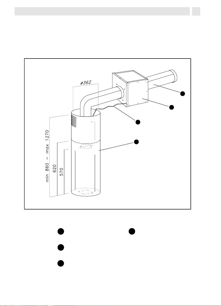
A
B
C
D
A
B
C
D
- DESCRIPTION DE VOTRE APPAREIL
FR
cheminée
moteur extérieur
(DHK7000) (vendu
séparément)
câble de lìaison
tube sortie air (vendu
séparément)
8
Page 9

2/ COMMENT INSTALLER VOTRE HOTTE
-Vérifiez que la tension du réseau correspond à la tension mentionnée sur la plaque signalétique située à l’intérieur de la hotte.
-Si l’installation électrique de votre habitation nécessite une modification pour le branchement de votre appareil, faites appel à un électricien qualifié.
-La hotte est utilisée en version évacuation, ne raccordez pas l’appareil à un conduit d’évacuation de fumées de combustion (chaudière, cheminée, etc…) ou à une VMC (ventilation
mécanique contrôlée.
-Le conduit d’évacuation, quel qu’il soit ne doit pas déboucher dans les combles.
-Installez la hotte à une distance de sécurité d’au moins 70cm d’un plan de cuisson électrique,
gaz ou mixte.
Sortie vers l’extérieur: fig. 2
L’évacuation de l’air vers l’extérieur est possible grâce à l’installation d’un moteur séparé
DHK7000 (vendu séparément). La connexion de la hotte au moteur séparé DHK7000 doit
réalisé avec un tuyau d’un diamètre de 1mm au moins. Celui-ci peut-être flexible, en
être
aluminium et non enflammable. Le tuyau ne doit pas être inférieur à 1mm. LA HOTTE N’EST
PAS PREVUE POUR LE FONCTIONNEMENT EN MODE RECYCLAGE.
RACCORDEMENT ELECTRIQUE
Lors de l’installation et des opérations d’entretien, l’appareil doit être débranché du réseau
électrique, les fusibles doivent être coupés ou retirés. L’installation électrique générale est à
réaliser avant la mise en place de l’appareil dans le meuble.
Vérifiez que:
-la puissance de l’installation est suffisante,
-les lignes d’alimentation sont en bon état
-le diamètre des fils est conforme aux règles d’installation.
FR
- MONTAGE DE VOTRE HOTTE
L‘installation doit être conforme aux règlements en vigueur pour la ventilation des
locaux. En France, ces règlements sont indiqués dans le DTU 61.1 du CSTB. En particulier, l‘air évacué ne doit pas être envoyé dans un conduit utilisé pour évacuer les fumées
d‘appareils utilisant du gaz ou autre combustible. L‘utilisation de conduits désaffectés ne
peut se faire qu‘après accord d‘un spécialiste compétent. La distance minimale entre le
plan de cuisson et la partie la plus basse de la hotte doit être de 70 cm. Si les instructions
de la table de cuisson installée sous la hotte spécifient une distance plus grande que 70
cm, celle-ci doit être prise en compte.
- INSTALLATION
Avant l’installation, retirer les filtres anti-gras pour éviter d’endommager l’appareil. Pour retirer les filtres anti-gras, pousser la poignée vers la partie inférieure de la hotte et faire tourner
le filtre vers le bas tout en l’extrayant de son siège (Fig. A).
Attention: l’installation doit être effectuée au moins par deux personnes.
Avant de procéder à l’installation de la hotte, pourvoir à l’alimentation électrique, Au positionnement de la centrale externe et a la predisposition de l’ouverture d’evacuation.
9
Page 10
Fixer les rallonges (Fig. Partie A) à la plaque supérieure (Fig. ) avec la vis fournie en dotation. Positionner la plaque supérieure (Fig. .1) sur le plafond, pratiquer trous de 8 mm en
correspondance du gabarit de perçage.
Introduire les chevilles dans les trous (Fig. ,1 – A) et fixer la plaque au plafond avec les vis
(Fig. -1-B).
Fixer alors la structure inférieure (Fig. 6.) sur la hotte en faisant coïncider les trous avec les
vis métriques soudées sur le support du ventilateur (Fig. 6.1). Introduire les rondelles et les
écrous fournis en dotation (Fig. 6.-A) en les vissant à l’aide d’un outil adéquat.
Unir le conduit d’évacuation de l’air au groupe moteur au moyen d’un collier de serrage; introduire la structure supérieure (fig. 6.) sur la structure inférieure tout en réglant sa position
en fonction de la hauteur désirée et surtout selon la hauteur minimum nécessaire entre le plan
de cuisson et la hotte. Fixer les deux structures à l’aide des vis (Fig. 6. B).
Soulever alors la hotte avec la structure et les conduits déjà introduits jusqu’à ce que les
quatre ressorts (Fig. 6.6 –E) s’enclenchent dans la structure supérieure (Fig. 6.C). Lorsque
les deux parties sont enclenchées, fixer les deux éléments (Fig. .1, Fig. .) avec les vis de
sécurité (Fig. .A).
Relier le conduit de la hotte à l’ouverture d’évacuation de l’air.
Introduire ensuite les deux tubes télescopiques (fig. 6. et 6.) sur la partie inférieure de la
hotte, soulever entièrement le conduit et le fixer à la hotte avec les vis fournies en dotation
(Fig. 10)- Soulever le conduit supérieur jusqu’au plafond et le fixer avec les vis (Fig. 6.6 –D).
- RACCORDEMENT DE VOTRE HOTTE
Cet appareil est livré avec un câble d’alimentation H 05 VVF à 3 conducteurs de 0,75
mm2 (neutre, phase et terre). Il doit être branché sur réseau 220-240 V mono phasé par
l’intermédiaire d’une prise de courant normalisée CEI 60083 qui doit res ter accessible après installation, conformé ment aux règles d’installation. Notre responsabilité ne
saurait être engagée en cas d’accident consécutif à une mise à la terre inexistante ou
incorrecte.
Le fusible de votre installation doit être de 10 ou 16 A. Si le câble d’alimentation est endommagé, faites appel au service après-vente afin d’éviter un danger.
Attention:
Si la hotte présente une quelconque anomalie, débranchez l’appareil ou enlevez le fusible
correspondant à la ligne de branchement de l’appareil.
10
Page 11
3/ COMMENT FONCTIONNE VOTRE HOTTE
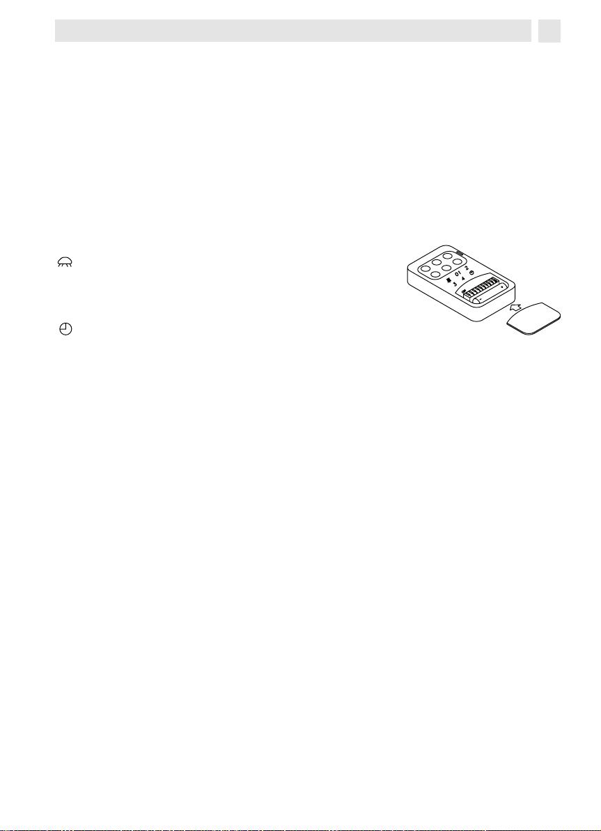
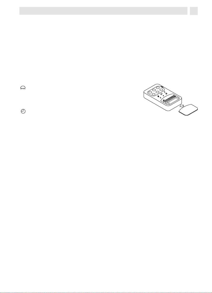
La télécommande est munie de 6 touches pour la commande à distance. Lorsque vous actionnez le temporisateur (touche D), la hotte fonctionne pendant 10 minutes, après quoi elle
s’arrête automatiquement.
Caractéristiques techniques du commande a distance:
- Alimentation par piles : 1V
- Fréquence de travail : ,9 Mhz
- Consommation max. : mA
- Température de fonctionnement : -0 + 70 °C
- Dimensions : x7x1 mm.
Description du fonctionnement:
Pour la gestion des fonctions de la hotte, l’émetteur est équipé de 6 touches, spécifiées comme suit:
: interrupteur ON/OFF éclairage
01 : interrupteur ON (1ère vitesse) OFF moteur
: interrupteur ème vitesse
: interrupteur ème vitesse
: interrupteur ème vitesse
: temporisateur 10 minutes.
Configuration standard
Sur la configuration de construction, toutes les installations “hotte-télécommande” ont un
même code de transmission (dip-switch n° 6-7-8-9-10 sur ON).
Si on installe au même endroit deux hottes ou si elles sont trop près l’une de l’autre, le
fonctionnement peut en ressentir. Il faut, dans ce cas, changer le code d’une seule télécommande.
FR
Changement du code
Pour changer le code de transmission de la télécommande, procéder comme suit: ouvrir le
couvercle et extraire la pile, sélectionner l’un des dip switch 7-8-9-10 sur OFF (le switch 6
doit rester sur ON).
Initialisation du nouveau code
Après avoir changé le code, procéder comme suit:
frapper la touche d’arrêt général de la hotte (fig. B), puis rétablir la connexion électrique en
frappant à nouveau cette touche (Fig. B); on dispose alors de 1 secondes pour frapper la
touche ON/OFF pour que la hotte se synchronise avec le nouveau code.
Touche d’urgence fig.3B
Si la télécommande ne fonctionne pas, pour éteindre l’appareil, frapper la touche d’urgence
qui se trouve près de la lampe. Après les réparations éventuelles, rétablir la touche d’urgence.
Les produits sont munis d’un dispositif électronique qui permet l’arrêt automatique après
quatre heures de fonctionnement depuis la dernière opération effectuée.
11
Page 12
4/ COMMENT NETTOYER VOTRE HOTTE
Un entretien soigné est une garantie de bon fonctionnement et de bon rendement de votre
appareil dans le temps.
FR
La hotte doit être mise hors tension, soit en retirant la prise, soit en actionnant le
disjoncteur, avant que les filtres métalliques soient enlevés. Après le nettoyage, les filtres métalliques doivent être de nouveau fixés conformément aux instructions.
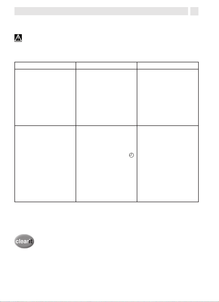
ENTRETIEN COMMENT PROCEDER?
N’utilisez jamais de tam-
Enveloppe et accessoires
Filtre
cassette
Pour préserver votre appareil, nous vous recommandons d’utiliser les produits d’entretien Clearit.
pons métalliques, de produits abrasifs ou de bros-
ses trop dures.
Après
0 heures de fonctionnement de la hotte le tableau
à poussoirs signalera la saturation du filtre en énticelant tous les poussoirs. Le
signal pourra être arrêté en
pressant l’interrupteur tem-
porisateur
grille anti-graisse, poussez
la poignée vers l’arrière de
la hotte et faites tourner la
grille vers le bas, en la retirant de sa place. Pour insérer
la grille exécutez l’opération
. Pour retirer la
contraire.
PRODUITS/ACCESSOIRES
A UTILISER
Pour nettoyer la carrosserie
et le hublot d’éclairage, utilisez exclusivement des nettoyants ménagers du commerce dilués dans de l’eau,
puis rincez à l’eau claire
et essuyez avec un chiffon
doux.
Pour nettoyer la grille lavezla à la main ou dans le lavevaiselle. Nettoyez la grille
périodiquement, au moins
tous les deux mois.
L’expertise des professionnels
au service des particuliers
Clearit vous propose des produits professionnels et des solutions adaptées pour l’entretien
quotidien de vos appareils électroménagers et de vos cuisines. Vous les trouverez en vente chez
votre revendeur habituel, ainsi que toute une ligne de produits accessoires et consommables.
1
Page 13

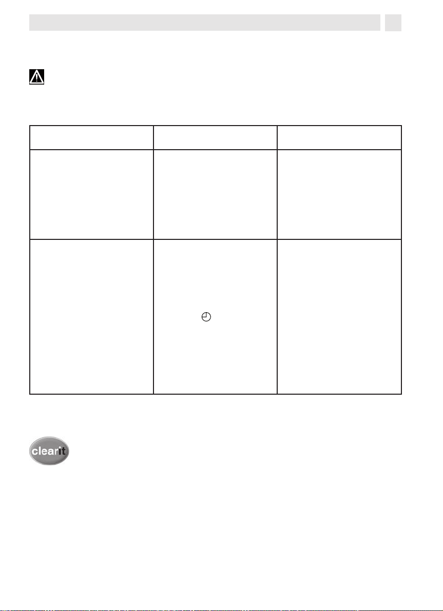
5/ ANOMALIES DE FONCTIONNEMENT
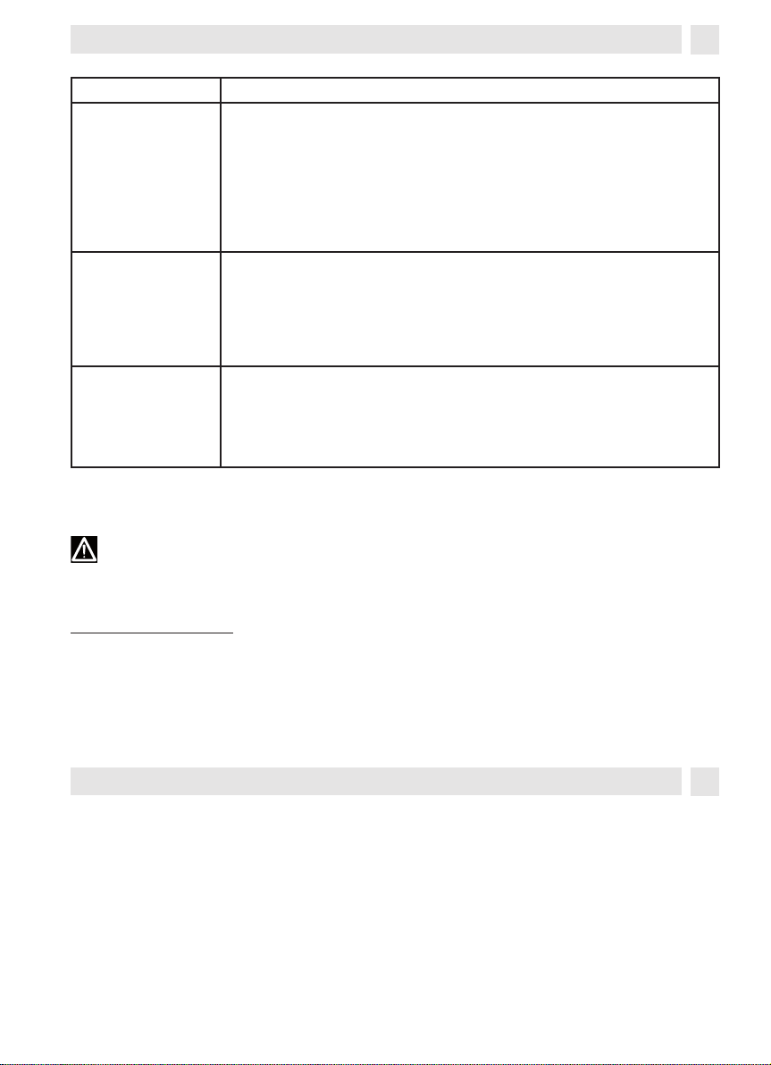
SYMPTOMES SOLUTIONS
Vérifiez que:
La hotte ne fonc-
tionne pas...
• il n’y a pas de coupure de courant.
• une vitesse a été effectivement sélectionnée.
• le connecteur de la centrale externe (DHK7000) soit branché correctement
FR
La hotte a un rendement insuffi-
sant...
La hotte s’est arrêtée au cours du
fonctionnement
Vérifiez que:
• la vitesse moteur sélectionnée est suffisante pour la quantité de
fumée de vapeur dégagée.
• la cuisine est suffisamment aérée pour permettre une prise d’air.
Vérifiez que:
• il n’y a pas de coupure de courant.
• le dispositif à coupure omnipolaire ne s’est pas enclenché.
- COMMENT CHANGER LA LAMPE
Avant toute intervention, la hotte doit être mise hors tension, soit en retirant la prise,
soit en actionnant le disjoncteur.
Lampe dichroique:
Pour remplacer la lampe halogène, extraire cette dernière à l’aide d’un petit tournevis ou d’un
outil pointu pouvant s’introduire entre la lampe et son siège. Remplacer la lampe avec une
autre ayant les mêmes caractéristiques (fig. 7).
1
Page 14
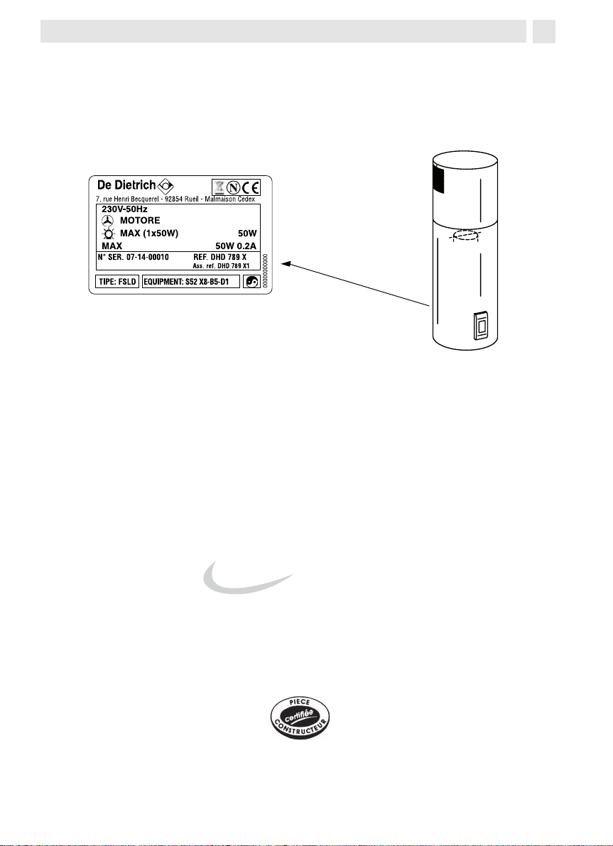
6/ SERVICE APRES-VENTE
0892 02 88 04*
FR
- INTERVENTIONS
Les éventuelles interventions sur votre appareil doivent être effectuées par un professionnel
qualifié dépositaire de la marque. Lors de votre appel, mentionnez la référence complète de
votre appareil (modèle, type numéro de serie). Ces renseignements figurent sur la plaque signalétique collée à l’intérieur de la hotte.
Ceci est un example
- RELATIONS CLIENTS
Pour en savoir plus sur tous les produits de la marque:
informations, conseils, les points de vente, les spécialistes après-vente.
Pour communiquer:
nous sommes à l’écoute de toutes vos remarques, suggestions, propositions auxquelles nous
vous répondrons personnellement.
Vous pouvez nous écrire: SERVICE CONSOMMATEURS DE DIETRICH
BP 9526
95069 GERGY PONTOISE CEDEX
ou nous téléphoner au:
euro TTC/mn à partir d’un poste fixe => tarif en vigueur à la date d’impression du do-
0,
cument.
PIÉCES D’ORIGINE
Lors d’une intervention d’entretien, demandez l’utilisation exclusive de pièces détachées
certifiées d’origine.
*Service fourni par FagorBrandt, locataire gérant, société par actions simplifiée au capital
0.000.000 euros-/7 avenue des Béthunes, 910 Saint Ouen l’Aumône-RCS Nanterre 0
0 196.
1
Page 15

FR
www.dedietrich-electromenager.com
Sehr geehrter Kunde,
6
DE
EN
ES
IT
NL
PT
CS
PL
HU
EL
DA
SK
SV
16
6
6
6
66
76
86
96
106
116
1
6
16
Wir bedanken uns bei Ihnen, dass Sie sich für eine Dunstabzugshaube von
DE DIETRICH entschieden haben.
6
Unsere Forschungsteams haben für Sie eine neue Generation an Geräten
entwickelt, die in ihrer ästhetischen Qualität, in ihrer Funktionalität und in
ihrer technischen Entwicklung außergewöhnliche Produkte darstellen und
so unsere Erfahrung bezeugen.
Ihre neue Dunstabzugshaube von DE DIETRICH fügt sich harmonisch in
ihre Küche und vereint Abzugsleistung und leichte Handhabung vollkommen. Wir bieten Ihnen ein unübertreffliches Produkt.
In der Produktpalette von DE DIETRICH können Sie darüber hinaus eine
große Auswahl an Öfen, Mikrowellen, Kochfeldern, Geschirrspülmaschinen
und einbaubaren Kühlschränken finden, die sich frei mit Ihrer Dunstabzugshaube kombinieren lassen.
Da unser Ziel natürlich die Kundenzufriedenheit mit unseren Produkten ist,
steht Ihnen unser Kundenservice zur vollen Verfügung, um Anfrage jeder
Art zu beantworten und nützliche Hinweise entgegen zu nehmen (Kontakthinweise finden Sie am Ende dieser Anleitung).
Besuchen Sie uns auch im Internet unter www.dedietrich-elecromanager.
com; hier finden Sie neben nützlichen Informationen auch unsere letzten
Innovationen.
DE DIETRICH
Neue Wertobjekte
In der Absicht unsere Produkte ständig zu verbessern, behalten wir uns das Recht
vor, an den technischen, funktionellen und ästhetischen Eigenschaften alle Veränderungen vorzunehmen, die sich aus ihrer Weiterentwicklung ergeben.
Wichtig: Bevor sie das Gerät in Funktion nehmen, lesen Sie die Installati-
onsanleitung aufmerksam durch und machen Sie sie mit der Bedienung Ihrer
Dunstabzugshaube vertraut.
1
Page 16

INHALT
1/ ALLGEMINE HINWEISE
- Sicherheitshinweise 17
- Gerätebeschreibung 18
DE
2 / INSTALLATION DER DUNSTABZUGSHAUBE
- Einbau der Dunstabzugshaube
- Installation 19
- Anschluss der Dunstabzugshaube 0
3 / FUNKTIONSWEISE DER DUNSTABZUGSHAUBE 21
4 / REINIGUNG DER DUNSTABZUGSHAUBE 22
5 / UNREGELMÄSSIGKEITEN IN DER FUNKTIONSWEISE
- Ersetzen der Lampe
6 / KUNDENDIENST 23
19
16
Page 17

1/ ALLGEMINE HINWEISE
Wichtig: Bewahren Sie die vorliegende Bedienungsanleitung mit dem Gerät auf. Sollte das
Gerät verkauft oder abgegeben werden, vergewissern Sie sich, dass dies mit der vorliegenden
Bedienungsanleitung geschieht. Wir danken Ihnen dafür, dass Sie die Hinweise vor der Installation und Inbetriebnahme des Gerätes beachten. Dies dient Ihrer Sicherheit und der Sicherheit
anderer.
Der Hersteller haftet nicht für Störungen, Schäden oder Brände, die infolge der Nichtbeachtung dieser Vorschriften an oder durch das Gerät entstehen sollten.
DE
- SICHERHEITSHINWEISE
Diese Abzugshauben wurden für den häuslichen Gebrauch durch Privatpersonen entwickelt.
Das Gerät darf nur von Erwachsenen bedient werden. Achten Sie darauf, dass Kinder das Gerät
nicht berühren und es nicht als Spielzeug verwenden. Versichern Sie sich darüber hinaus, dass
die Einstellungen nicht durch sie manipuliert werden.
- Entfernen Sie oder lassen Sie bei Lieferung sofort die Verpackung entfernen. Überprüfen Sie den
allgemeinen Zustand des Gerätes. Vermerken Sie eventuelle Mängel auf dem Kassenbon, von dem
Sie sich eine Kopie anfertigen sollten. Ihr Gerät ist für den normalen häuslichen Gebrauch bestimmt.
Das Gerät darf nicht für kommerzielle, industrielle oder andere Zwecke verw
- Verändern Sie nie und versuchen Sie auch nie die Eigenschaften des Gerätes zu verändern. Dies
würde eine Gefahr darstellen.
Reparaturen dürfen ausschließlich von bevollmächtigen Fachpersonal vorgenomme
Trennen Sie die Dunstabzugshaube immer vom Stromnetz bevor Sie die Reinigung oder Wartungsarbeiten vornehmen.
- Lüften Sie die Umgebung ausreichend, wenn die Dunstabzugshaube gleichzeitig mit anderen
Geräten in Funktion ist, wobei die anderen Geräte durch andere Stromanschlüsse versorgt werden
sollten. Andernfalls besteht die Gefahr, dass die Dunstabzugshaube entzündbare Gase ansaugt.
- Es ist verboten unter der Abzugshaube Lebensmittel auf offener Flamme zuzubereiten oder den
Gasherd ohne Kochbehälter angezündet zu haben (werden die Flammen von der Dunstabzugshaube angesaugt, besteht die Gefahr das Gerät zu beschädigen).
- Wird unter der Abzugshaube frittiert, muss ständige Aufmerksamkeit geleistet werden, da sich
heiße Öle und Fette entzünden können.
Halten Sie die zeitlichen Abstände für die Reinigung ein und ersetzten Sie die Filter in den erforderlichen Zeitabständen. Fettansammlungen können Brände verursachen.
- Der Installation der Dunstabzugshaube über Brennstoffherden (Holz, Kohle, ...) ist nicht erlaubt.
Verwenden Sie zur Reinigung Ihrer Dunstabzugshaube niemals Wasserdampfreinigungsgeräte oder
Reinigungsgeräte mit Hochdruck (Sicherheitsregeln bezüglich elektronischer Geräte)
In der Absicht unsere Produkte ständig zu verbessern, behalten wir uns das Recht vor, an den
technischen, funktionellen und ästhetischen Eigenschaften alle Veränderungen vorzunehmen,
die sich aus ihrer Weiterentwicklung ergeben.
Um zukünftig die Daten bezüglich Ihres Gerätes schnell zur Hand zu haben, raten wir Ihnen
diese auf der Seite „Kundenbetreuung nach Kauf“ einzutragen. (Auf dieser Seite wird Ihnen
darüber hinaus erklärt, wo Sie die entsprechenden Daten an Ihrem Gerät finden können)
endet werden.
n werden.
Achtung: Im Falle, dass Ihre Küche durch ein Gerät beheizt wird, das an den Abzugs-
schacht (Schornstein) angeschlossen ist, muss die Abzugshaube im Umluftbetrieb installiert
werden. Benutzen Sie die Dunstabzugshaube nie ohne Filter. Darüber hinaus müssen Sie für
eine ausreichende Belüftung sorgen, sollte die Dunstabzugshaube zusammen mit anderen
Gas- oder Brennstoffgeräten genutzt werden.
17
Page 18

1/ ALLGEMINE HINWEISE
A
B
C
D
A
B
C
D
- GERÄTEBESCHREIBUNG
DE
Kamin
Externer Motor
(DHK7000)
trennt verkauft)
Anschlusskabel
(wird ge-
Luftabzugsrohr
getrennt verkauft)
(wird
18
Page 19
2/ INSTALLATION DER DUNSTABZUGSHAUBE
- Während der Installation und Eingriffen muss das Gerät vom Stromnetz getrennt werden.
- Vergewissern Sie sich, dass die Spannungswerte des Stromnetzes mit den Werten des geräteintern angebrachten Typenschilds übereinstimmen.
- Sollte die Notwendigkeit einer elektrotechnischen Änderung in Ihrer Wohnung bestehen, wenden
Sie sich an einen Fachmann.
- Schließen sie das Gerät niemals an einen Abzugsschacht für brennbaren Rauch (Heizkessel,
Schornsteine, usw.) oder an ein mechanisch kontrolliertes Belüftungssystem an.
- Der Abzugsschacht, egal welchen Typs, darf niemals in Übereinstimmung mit dem Dachgeschoss
hinaus stehen.
- Installieren sie die Dunstabzugshaube in einem Sicherheitsabstand von mindestens 70 cm von
der Kochfläche (elektrisch, Gas, oder gemischt).
Wenn sie einen Luftabzug nach Außen besitzen:
Der Ausstoß der Luft nach außen ist durch Installation eines separaten Motors DHK7000 (wird getrennt verkauft) möglich. Der Anschluss der Abzugshaube an dem separaten Motor DHK7000 muss
durch eine Leitung mit Mindestdurchmesser 1 mm vorgenommen werden. Diese Leitung kann
flexibel, aus Aluminium hergestellt sein und muss unentzündlich sein. Der Durchmesser darf nicht
unter 1 mm liegen. DIESE ABZUGSHAUBE IST NICHT FÜR DIE VERWENDUNG IM UMLUFTBETRIEB
AUSGELEGT.
ELEKTROANSCHLUSS
Ihr Gerät entspricht den EG- Richtlinien 2006/65/CEE (Niederspannungsrichtlinie) und
2004/108/CE (Elektromagnetische Vertäglichkeit)
Während der Installation und Wartungsarbeiten muss das Gerät vom Stromnetz getrennt und die
Schmelzsicherungen abgeschaltet oder entfernt werden. Der Stromanschluss muss ausgeführt
werden, bevor das Gerät ins Möbelstück eingesetzt wird.
Vergewissern Sie sich, dass:
- die Stromstärke ausreichend ist,
- die Stromverbindungen in gutem Zustand sind,
- der Durchmesser der Kabel mit den Installationsregeln übereinstimmt.
DE
- EINBAU DER DUNSTABZUGSHAUBE
Die Installation muss entsprechend den geltenden Vorschriften bezüglich einer ausreichenden Belüftung von geschlossenen Räumen durchgeführt werden. In Frankreich sind
diese Vorschriften in DTU 61.1 des CSTB enthalten. Im Besonderen darf die abzugebende
Luft nicht in Luftschächte geführt werden, die für den Abzug von Rauch oder anderen Gasund Brennstoffgeräten benutzt werden. Die Nutzung von Abzugsschächten außer Betrieb ist
ausschließlich nach der Zustimmung eines qualifizierten Fachmannes möglich. Der Abstand
zwischen der Kochfläche und dem unteren Rand der Dunstabzugshaube muss mindestens 70
cm betragen. Sollten die Vorschriften für die installierte Kochfläche einen größeren Abstand
vorsehen, ist dem gerecht zu werden.
- INSTALLATION
Um Schäden am Gerät zu vermeiden müssen vor der Installation die Fettfilter entfernt werden. Dazu den
Griff nach unten drücken, den Filter nach unten drehen und aus seiner Aufnahme nehmen (Abb. A).
Achtung: Zur Installation sind mindestens zwei Personen erforderlich.
Vor Installation der Abzugshaube muss der Stromanschluss ausgeführt, Das externe steuergerät positioniert und die auslassöffnung hergestellt werden.
19
Page 20
Die Verlängerungsteile (Abb., Teil A) an der oberen Platte (Abb..) anhand der mitgelieferten
Schraube befestigen. Die obere Platte (Abb. .1) an der Decke befestigen und mithilfe der
Bohrschablone Bohrungen Durchm. 8 mm herstellen.
Die Stifte in die Öffnungen (Abb. ,1 – A) einsetzen und die Platte mit den Schrauben an der
Decke befestigen (Abb. -1-B).
Die untere Tragstruktur (Abb. 6.) an der Abzugshaube so anbringen, dass die Bohrungen mit
den metrischen Schrauben übereinstimmen, die an der Halterung des Ventilators (Abb. 6.1)
angeschweißt sind. Die mitgelieferten Unterlegscheiben und Muttern einsetzen (Abb. 6.-A)
und mit einem geeigneten Werkzeug festziehen.
Das Luftabzugsrohr mithilfe einer Manschette an der Motoreinheit befestigen. Die obere
Tragstruktur (Abb. 6.) auf den unteren Teil aufsetzen und dabei die Position entsprechend
der gewünschten Höhe und insbesondere unter Berücksichtigung des notwendigen Mindestabstands zwischen Kochplatte und Abzugshaube regulieren. Die beiden Tragstrukturen mit
den Schrauben (Abb. 6. B) befestigen. Dann die Abzugshaube zusammen mit der Tragstruktur und den bereits eingesetzten Rohren heben, bis die vier Federn (Abb. 6.6 –E) in die Bohrschablone (Fig. 6.C) eingreifen. Nachdem die beiden Teile miteinander verbunden wurde n
sind die beiden Elemente (Abb. .1, Abb. .) anhand der Sicherungsschrauben (Fig. .A) zu
befestigen. Das Abzugsrohr der Haube in die Luftauslassöffnung einführen.
Danach die beiden Teleskoprohre (Abb. 6. und 6.) in den unteren Teil der Abzugshaube
einführen, das Rohr ganz anheben und mit den mitgelieferten Schrauben an der Abzugshaube befestigen (Abb. 10). Das obere Rohr bis zur Decke schieben und dort mit den Schrauben
(Abb. 6.6 –D) befestigen.
- SROMANSCHLUSS DER DUNSTABZUGSHAUBE
Dieses Gerät ist mit einem Versorgungskabel H05 VVF mit 3 Leitern zu je 0,75 mm2
(neutral, Phase und Erdung) ausgestattet. Es muss an ein Stromnetz mit 220 – 240 V
durch eine normale Steckdose CEI 60083 angeschlossen werden, an die auch nach der
Installation Zugriff besteht und die mit den Installationsvorschriften übereinstimmt. Für
den Fall eines Unfalls, der durch eine fehlende oder nicht korrektre Erdung verursacht
wird, wird jegliche Verantwortung abgelehnt. Die verwendete Schmelzsicherung muss
zwischen 10 und 16A sein. Sollte das Stromversorgungskabel beschädigt sein, wenden
Sie sich an die Kundenbetreuung nach Kauf um jegliches Risiko auszuschließen.
Achtung:
Sollte die Dunstabzugshaube Unregelmäßigkeiten in ihrer Funktionsweise aufzeigen, nehmen Sie
das Gerät vom Netz oder entfernen sie die entsprechenden Schmelzsicherungen des Gerätes.
0
Page 21
3/ FUNKTIONSWEISE DER DUNSTABZUGSHAUBE
Die Fernsteuerung ist mit 6 Tasten für die Steuerung der Dunstabzugshaube ausgestattet.
Wenn der Timer (Taste D) betätigt wird, läuft die Abzugshaube 10 Minuten lang und wird dann
automatisch abgeschaltet.
DE
Technische Merkmale der Fernsteuerung:
- Versorgungsbatterien
- Betriebsfrequenz : ,9 Mhz
- Stromaufnahme max. : mA
- Betriebstemperatur : -0 + 70 °C
- Abmessungen : x7x1 mm.
Funktionsbeschreibung:
Zur Steuerung der Funktionen ist das Gerät mit folgenden 6 Tasten ausgestattet:
: Schalter EIN/AUS Beleuchtung
01 : Schalter EIN /(erste Geschwindigkeitsstufe) AUS Motor
: Schalter zweite Geschwindigkeitsstufe
: Schalter dritte Geschwindigkeitsstufe
: Schalter vierte Geschwindigkeitsstufe
: Minuten- Timer
Standard- Konfiguration
In der fabrikseitigen Konfiguration haben alle Fernsteuerungsanlagen der Abzugshauben den
gleichen Übertragungscode (Dip- Schalter Nr. 6-7-8-9-10 auf ON).
Wenn am gleichen Ort zwei Abzugshauben installiert werden, oder wenn diese zu nahe beieinander liegen, kann es zu Funktionsstörungen kommen. Aus diesem Grund muss dann der
Code einer der beiden Fernsteuerungen geändert werden.
Änderung des Codes
Zur Änderung des Übertragungscodes der Fernsteuerung ist wie folgt vorzugehen: den Deckel
öffnen und die Batterie wechseln. Einen der Dip- Schalter Nr. 7-8-9-10 auf OFF stellen (der
Dip- Schalter Nr. 6 muss auf ON bleiben).
Initialisierung des neuen Codes
Nachdem der Code der Fernsteuerung geändert wurde, ist wie folgt vorzugehen:
Die Stoppaste des Abzugshaube (Abb. B) drücken. Dann durch Betätigen der gleichen Taste
(Abb. B) die Stromversorgung wieder einschalten. Danach muss innerhalb von 1 Sekunden
die Taste ON/OFF der Beleuchtung betätigt werden, damit sich die Abzugshaube auf den neuen Code synchronisiert.
: 1V
Notstopp – Taste Abb 3B
Sollte die Fernsteuerung nicht funktionieren, ist zum Abschalten des Geräts die Notstopp- Taste neben der Beleuchtungslampe zu betätigen. Nach der eventuell erforderlichen Reparatur,
die Notstopp- Taste wieder in ihren ursprünglichen Zustand bringen.
Die Produkte sind mit einer elektronischen Einrichtung versehen, die nach Stunden Betrieb
ab der letzten Betätigung das automatische Abschalten ermöglicht.
1
Page 22
4/ REINIGUNG DER DUNSTABZUGSHAUBE DE
Eine sorgfältige Pflege garantiert auf Dauer eine gute Leistung und Funktionstüchtigkeit des
Geräts.
DE
Die Dunstabzugshaube muss vom Stromnetz getrennt werden, bevor die Metallfilter
entnommen werden können. Nach der Reinigung sind die Metallfilter wie in der Anleitung beschrieben wieder einzusetzen.
WARTUNG WIE IST VORZUGEHEN? PUTZ- UND HILFSMITTEL
Um die Oberfläche der Abzugshaube und die Lampenoberfläche zu reinigen,
verwenden Sie ausschließlich
in Wasser verdünnte Reinigungsmittel für den häuslichen Gebrauch, die Sie im
Handel kaufen können. Danach mit klarem Wasser abwaschen und mit einem wei-
chem Tuch trocken wischen.
Reinigen Sie das Gitter von
Hand oder in der Spülmaschine. Reinigen Sie das Gitter mindestens alle zwei Mo-
nate.
Außere Geräteoberfläche und
Zubehör
Filterpatronen
Verwenden Sie keinesfalls
Metallschwämme, Scheuermittel oder zu harte Bür-
Nach
gnalisiert ein Aufleuchten aller Tasten die Sättigung des
Filters. Sie können dieses
Signal abschalten, indem Sie
die Timer- Taste drücken .
Um das Antifettgitter zu entfernen, drücken Sie den Griff
nach hinten und drehen das
Gitter nach unten, um es so
aus seiner Halterung heraus
zu nehmen. Um das Gitter
wieder einzusetzen, führen
Sie die Schritte in umgekehr-
sten.
0 Betriebsstunden si-
ter Weise aus.
Um eine gute Pflege für Ihr Gerät zu gewährleisten, empfehlen wir Ihnen die Reinigungsprodukte
von Clearit.
Clearit Professionelle Erfahrung
für den privaten Gebrauch
Clearit bieten Ihnen professionelle Produkte und Lösungen für die tägliche Wartung Ihrer Haus-
haltsgeräte und Ihrer Küche. Sie können Clearit zusammen mit einer kompletten Produktlinie an
Zubehör bei Ihrem üblichen Verkäufer finden.
Page 23
5/ UNREGELMÄSSIGKEITEN IN DER FUNKTIONSWEISE
ANZEICHEN LÖSUNG
Versichern Sie sich, dass:
DE
Die Abzugshaube
funktioniert nicht..
Die Abzugshaube
funktioniert nicht
richtig
Die Abzugshaube
blockiert sich während des Betriebs
von allein.
• kein Stromausfall besteht,
• die gewünschte Betriebsstufe wirklich ausgewählt wurde.
• der Stecker des externen Steuergeräts (DHK7000) einwandfrei angeschlossen ist
Versichern Sie sich, dass:
• die Motorgeschwindigkeit für die Rauch- und Dampfmenge hoch
genug gewählt ist,
• die Küche ausreichend belüftet ist, um einen notwendigen Luftansog
zu gewährleisten,
Versichern Sie sich, dass:
• kein Stromausfall besteht,
• die Unterbrechungsvorrichtung nicht ausgelöst worden ist
- ERSETZEN DER LAMPE
Nehmen Sie die Abzugshaube vor jedem Eingriff vom Stromnetz, indem Sie den Stek-
ker aus der Steckdose ziehen oder die Nottaste betätigen.
Kaltlichtspiegellampe:
Zum Austausch die Kaltlichtspiegellampe durch Einscheiben eines kleinen Schraubenziehers
oder eines beliebigen spitzen Werkzeugs zwischen Lampe und entfernen. Die Lampe gegen
eine neue mit gleichen Merkmalen austauschen (Abb. 7).
6/ KUNDENDIENST
Eingriffe an Ihrem Gerät dürfen nur:
- von Ihrem Händler oder
- von einem sonstigen Fachmann und Vertragshändler der Marke durchgeführt werden.
Geben Sie bei der Meldung einer Störung die vollständige Typenbezeichnung Ihres Gerätes an
(Modell, Typ, Seriennummer). Diese Angaben finden Sie auf einem an Ihrem Gerät angebrachten Schild.
DE
Page 24

Page 25

FR
www.dedietrich-electromenager.com
Dear client,
6
DE
EN
ES
IT
NL
PT
CS
PL
HU
EL
DA
SK
SV
16
6
6
6
66
76
86
96
106
116
1
6
16
You have just purchased a DE DIETRICH range ventilation hood, and we
thank you for your purchase.
6
Our research and development teams have designed a new generation of
appliances for you, which, because of their aesthetics, functionality, and
technological evolution, are truly exceptional products representative of our
design experience.
Your new DE DIETRICH range ventilation hood will harmoniously suit your
kitchen and will perfectly combine ventilation performance and ease of use.
We simply want to offer you an excellent product.
Within the DE DIETRICH product line you will find a wide range of ovens,
microwave ovens, cookers, washing machines, and fitted refrigerators that
can be freely coordinated with your new DE DIETRICH range ventilation
hood.
Naturally, since our objective is the satisfaction of our clients towards our
products, our customer service is at your total disposition to respond to any
request and receive any useful suggestion (reference details at the end of
the booklet).
Visit our web site www.dedietrich-elecromanager.com where you will find
our latest innovations as well as all useful information.
DE DIETRICH
The new objects of value
Constantly seeking to improve our products, we reserve the right to modify their
technical, functional, or aesthetic characteristics as they evolve.
Important: Before activating the appliance, read the installation and usage
manual carefully to familiarise yourself more quickly with its operation.
Page 26

CONTENTS
1/ FOR THE ATTENTION OF THE USER
- Safety instructions 7
- Description of the appliance 8
EN
2 / INSTALLING THE HOOD
- Mounting the hood
- Installation 9
- Connecting the hood 0
3 / HOW THE HOOD WORKS 31
4 / CLEANING THE HOOD 32
5 / OPERATIONAL ANOMALIES
- Changing the light bulb
6 / AFTER SALES SERVICE 33
9
6
Page 27
1/ FOR THE ATTENTION OF THE USER
Important: keep these instructions for use with the appliance. If the appliance should be
sold or passed on to others, make sure that the instructions are passed on with it. We thank
you for taking note of these suggestions before installing and using the appliance. They have
been written for your personal safety and the safety of others.
The manufacturer cannot accept any liability for problems, damage, or fire caused on or by the
appliance due to failure to follow the instructions in this manual.
EN
- SAFTEY INSTRUCTIONS
These hoods have been designed for personal use in the home. The appliance must be used
by adults. Take care that children do not touch the appliance and do not use it as a toy. Make
sure that children do not operate the controls.
- Upon delivery of the appliance, remove the packing material yourself or have it removed immediately. Check the overall condition of the appliance. Note any observations on the delivery bill and
keep a copy. Your appliance is designed for normal use in the home. It is not designed for commercial or industrial use, or for purposes other than those for which it was designed.
- Do not ever modify, or attempt to modify, the design characteristics of this appliance. This could
result in danger.
Repairs must be performed only by an authorised specialist.
Always disconnect the hood before carrying out cleaning or maintenance operations.
- Adequately ventilate the area in case the hood is activated simultaneously with other appliances powered from non-electrical sources so that the hood does not ventilate these combustion
fumes.
- It is prohibited to cook food over open flames or operate gas hobs without pots or pans on them
under the hood itself (the flames sucked into the hood might damage the appliance).
- Deep frying under the appliance must be done under constant supervision as hot oils and fats
may ignite.
Respect the guidelines for cleaning and replacement of the filters. Accumulated deposits of grease
are a fire hazard
- The use of combustible materials (wood, charcoal, etc…) on the hobs is not permitted
Never use steam or high-pressure devices for cleaning your hood (regulations regarding electrical
safety).
Constantly seeking to improve our products, we reserve the right to modify their technical, functional, or aesthetic characteristics as they evolve.
In order to find the notes regarding your appliance easily in the future, we advise you to collect
them on the page “After sales service and customer relations”. (This page also explains where to
find them on your appliance).
Attention: If your kitchen is heated by a device hooked up to a chimney (i.e., a wood
stove), you should install the recirculation mode of the hood. Never use the hood without the
filter cartridges. Furthermore, you must province adequate ventilation to the area when your
kitchen hood is used at the same time as devices that operate with gas or other combustible
materials.
7
Page 28
1/ FOR THE ATTENTION OF THE USER
A
B
C
D
A
B
C
D
- DESCRIPTION OF THE APPLIANCE
EN
flue
external motor
(DHK7000)
rately)
connection cable
(sold sepa-
air exhaust pipe
separately)
(sold
8
Page 29
2/ INSTALLING THE HOOD
- During installation, or in the case of repairs, the appliance must be unplugged.
- Make sure that the electrical tension of the power source corresponds to the electrical tension indicated on the information plate on the inside of the hood.
-If you need to modify the electrical layout of your house in order to be able to use the hood, call a
qualified technician.
- Never hook up the appliance to a discharge conduit used for combustion fumes (boilers, chimneys,
etc.) or a CMV unit (Controlled Mechanical Ventilation).
- The discharge conduit, whatever it may be, must never exit into the attic.
- Install the hood at a safe distance of at least 70 cm from the hob surface, whether they are electric,
gas, or mixed.
If you have an outlet to the outside:
Air exhaust to the outside is made possible by installing a separate DHK7000 motor (sold separately).
The hood needs to be connected to the separate DHK7000 motor using a tube with a diameter of at
least 1 mm. The tube should be flexible, in aluminium and non flammable. The tube must never
have a diameter of less than 1 mm. THIS HOOD IS NOT DESIGNED TO OPERATE IN RECIRCULATION
MODE.
ELECTRIAL HOOK UP
When you install the appliance and carry out maintenance, it must be unplugged from the
power source or the fuses must be disengaged or removed. Electrical hook up must be carried
out before the appliance is installed in the cabinet.
Check that:
- the power source is sufficient,
- power cords are in good condition,
- The diameter of the cables conforms to installation regulations.
EN
- MOUNTING THE HOOD
Installation must conform to the regulations in force regarding the ventilation of
enclosed environments. In France, these regulations are container in the DTU 61.1 of the
CSTB. In particular, discharged air must not be channelled into a conduit used for exhaust
discharge or discharge from devices that operate with gas or other combustible materials. The use of unused conduits is not permissible without the approval of a qualified
technician. The minimum distance between the hob surface and the lowest part of the
hood must be 70 cm. If the instructions for the cooker installed under the hood require
an even greater distance, this must take precedence.
- INSTALLATION
To prevent any damage to the appliance, remove the grease filters before installation. To
remove the grease filters, push the handle down towards the bottom of the hood and turn the
filter downwards, removing it from its seat at the same time (Fig. A).
Important: the installation process requires at least two people.
Before installing the hood, make sure that there is a nearby mains electricity point, position
the external controller and prepare the exhaust outlet opening.
Fix the extensions (Fig. , part A) to the top plate (Fig. ) using the screws provided. Position
the top plate (Fig..1) on the ceiling; make holes (8 mm) as shown in the template.
9
Page 30
Insert the pins into the holes (Fig. .1 – A) and screw the plate to the ceiling (Fig. .1 - B).
Then fix the lower structure (Fig. 6.) to the hood so that the holes meet up with the metric
screws welded to the fan support (Fig. 6.1). Insert the washers and nuts provided (Fig. 6.-A)
and tighten them using a suitable tool.
Join the air outlet pipe to the motor unit using a collar. Fit the top structure (Fig. 6.) into the
bottom structure and at the same time, adjust its position according to the required height
and above all to the minimum height necessary between the cook top and the hood. Secure
the two structures with screws (Fig. 6. B).
Then lift the hood with the structure and pipes already inserted until the four screws (Fig. 6.6
–E) hook onto the bottom structure (Fig. 6.C). Once the two parts have connected, fasten
them into place (Fig. .1, Fig. .) using the lock screws (Fig. .A).
Connect the hood pipe to the air exhaust opening.
Then insert the two telescopic pipes (Fig. 6. and 6.) into the bottom part of the hood; lift
the pipe completely and secure it to the hood with the screws provided (Fig. 10)- Raise the top
pipe as far as the ceiling and screw it into place (Fig. 6.6 –D).
- ELECTRICAL HOOK UP OF THE HOOD
This appliance is fitted with an H05 VVF 3 conductor, 0.75 mm2 (neutral, phase, and
ground) power cable. This can be hooked up to a 220 – 240 V mono-phase electrical network by way of a CEI 60083 regulation power socket that must remain accessible after
installation, in conformity to installation regulations.
We decline all responsibility in case of accident caused by a lack of ground connection
or incorrect ground connection. The fuse used must be 10 or 16 A. If the power cable is
damaged, call the after-sales service to avoid any risk.
Attention:
If the hood presents some form of anomaly, unplug the appliance or remove the fuse corresponding to the appliance’s power line.
0
Page 31

3/ HOW THE HOOD WORKS
The remote control has 6 buttons to control the hood. When you use the timer function button
(D), the hood will operate for 10 minutes before stopping automatically.
EN
Remote control technical characteristics:
- Battery power
- Operating frequency : ,9 Mhz
- Max. absorbed power. : mA
- Operating temperature : -0 + 70 °C
- Dimensions : x7x1 mm.
Operating description:
It has the following 6 buttons to control the appliance:
: lighting ON/OFF switch
01 : motor ON (first speed) OFF switch
: second speed switch
: third speed switch
: fourth speed switch
: 10-minute timer
Standard configuration
The factory settings for the transmission code of all “hood remote controls” is the same
(dipswitch no. 6-7-8-9-10 to ON).
If two hoods are installed in the same area or in any case, one hood is installed in close proximity to another, this could affect operation and therefore, it will be necessary to change the
code on one of the remote controls.
Changing the code
To change the transmission code for the remote control, proceed as follows: open the cover
and remove the battery then set one of the dipswitches 7-8-9-10 to OFF (dipswitch 6 must
remain set to ON).
Initialising the new code
Once the code on the remote control has been changed, proceed as follows:
Press the main stop button for the hood (Fig. B), then restore the electrical connection by
pressing the same button again (Fig. B); from this moment, you have 1 seconds to push the
ON/OFF button to synchronise the hood with the new code number.
: 1V
Emergency stop button Fig 3B
If the remote control does not work, press the emergency stop button, which is located next to
the light. After any necessary repairs have been made, reset the emergency stop button.
These appliances are fitted with an electronic device that causes them to switch off automatically hours from the last control operation.
1
Page 32

4/ CLEANING THE HOOD
Careful maintenance helps guarantee proper operation and good results from an appliance
over time.
EN
The hood must be unplugged from the electrical power source, both by unplugging
the appliance from the socket as well as de-activating the breaker, before removing the
metal filters. After cleaning, you must replace the metal filters as outlined in the instructions.
MAINTENANCE HOW TO PROCEED?
External surfaces and acces-
sories
Filter cartridge
To preserve the appliance we advise you to use Clearit maintenance products.
Do not use metallic
scrubbers, abrasive pro-
ducts, or hard brushes.
After
the keypad will signal that
the filter is saturated by
lighting up all of the buttons. Shut off this message by pressing the timer
switch . To remove the
anti-grease grill push the
handle toward the back of
the hood and rotate the
grill downward, removing
To replace the grill, do the
0 h of operation
it from its housing.
reverse.
ACCESSORY PRODUCTS TO
To clean the external surfaces of the hood and the light
housing screen use only commercially available household
detergents diluted in water.
Then rinse with clean water and
dry with a soft cloth.
To clean the grill, wash it by
hand or in the washing machine. Clean it at least every two
USE
months.
Clearit The experience of
professionals at your service.
Clearit offers appropriate professional products and solutions for the day-to-day maintenance
of your household appliances and kitchens.
You will find these products on sale at your usual retailer together with an entire line of acces-
sories and complementary products.
Page 33

5/ OPERATIONAL ANOMALIES
SYMPTOM SOLUTION
Check that:
The hood does not
work...
• there is not a power outage.
• a specific speed has actually been selected.
• The connector of the external controller (DHK7000) needs to be securely connected.
EN
The hood has low
output...
The hood stops in
the middle of ope-
ration
Check that:
• the motor speed selected is sufficient for the quantity of fumes
steam present.
• the kitchen is ventilated well enough to allow for air intake.
Check that:
• there is not a power outage.
• the omnipolar device has not tripped
- CHANGING THE LIGHT BULB
Before any maintenance, the hood must be disconnected from the power source, ei-
ther by unplugging the power cord from the wall socket or by deactivating the switch.
Dichroic light bulb:
To replace the halogen lamp, remove it using a small screwdriver or pointed tool that fits between the lamp and its housing. Replace the lamp with one that has the same characteristics
(Fig. 7).
6/ AFTER SALES SERVICE
EN
Any maintenance on your equipment should be undertaken by:
- either your dealer,
- or another qualified mechanic who is an authorized agent for the brand appliances.
When making an appointment, state the full reference of your equipment (model, type and
serial number). This information appears on the manufacturer’s nameplate attached to your
equipment.
Page 34

Page 35

FR
www.dedietrich-electromenager.com
Estimado cliente,
6
DE
EN
ES
IT
NL
PT
CS
PL
HU
EL
DA
SK
SV
16
6
6
6
66
76
86
96
106
116
1
6
16
Le agradecemos que Usted haya comprado una campana DE DIETRICH.
Nuestros equipos de investigación han proyectado para usted una nueva
6
generación de aparatos que, por su calidad estética, funcionalidad y evolución tecnológica representan productos excepcionales que son la prueba de
nuestra experiencia.
Su nueva campana DE DIETRICH se integrará con armonía en su cocina y
conjugará perfectamente capacidad de aspiración y facilidad de empleo.
Hemos querido ofrecerle un producto excelente.
En la gama de los productos DE DIETRICH podrá encontrar además una
amplia variedad de hornos, hornos microondas, encimeras, lavavajillas, frigoríficos empotrados, que se pueden coordinar libremente con su nueva
campana DE DIETRICH.
Como nuestro objetivo, naturalmente, coincide con la satisfacción de nuestros clientes por nuestros productos, nuestro servicio de consumidores está
a su completa disposición, para responder a cualquier necesidad y para
aceptar cualquier útil sugerencia (las referencias al final de este manual).
Visite además nuestro sitio internet, www.dedietrich-elecromanager.com,
donde podrá encontrar nuestras últimas innovaciones además de tantas
informaciones útiles.
DE DIETRICH
Los nuevos objetos de valor
Con la intención constante de mejorar nuestros productos, nos reservamos el derecho de aportar a sus características técnicas, funcionales o estéticas, todas las
modificaciones que deriven de su evolución.
Importante: antes de poner en marcha el aparato leer atentamente el ma-
nual de instalación y uso para familiarizarse más rápidamente con su funcionamiento.
Page 36

ÍNDICE
1/ A LA ATENCIÓN DE LOS SEÑORES USUARIOS
- Instrucciones de seguridad 7
- Descripción del aparato 8
ES
2 / CÓMO INSTALAR LA CAMPANA
- Montaje de la campana
- Instalación 9
- Conexión de la campana 0
3 / CÓMO FUNCIONA LA CAMPANA 41
4 / CÓMO LIMPIAR LA CAMPANA 42
5 / DEFECTOS DE FUNCIONAMIENTO
- Cómo sustituir la lámpara
6 / SERVICIO POSTVENTA 43
9
6
Page 37

1/ A LA ATENCIÓN DE LOS SEÑORES USUARIOS
Importante: conserve estas instrucciones de uso junto con el aparato. Si el aparato se
vendiera o cediera a otras personas, asegúrese de que vaya acompañado de estas instrucciones. Agradecemos que tome nota de estos consejos antes de instalar y utilizar el aparato. Han
sido redactados por su seguridad personal y la de los demás.
El constructor declina toda responsabilidad derivada de cualquier inconveniente, daño o incendio provocado en o por el aparato y que fueran causados por no haber respetado las prescripciones presentes en estas instrucciones.
ES
- INSTRUCCIONES DE SEGURIDAD
Estas campanas han sido proyectadas para un empleo en ambiente doméstico por parte de
usuarios particulares. El aparato lo deben usar exclusivamente personas adultas. Vigile que
los niños no lo toquen y no lo empleen como un juego. Asegúrese además de que los niños
no manipulen los mandos.
- Cuando se le entregue el aparato, quite el embalaje inmediatamente. Compruebe su aspecto general.
Manifieste las eventuales observaciones escribiéndolas en el resguardo de entrega del cual conservará una
copia. Su aparato ha sido destinado al normal uso doméstico. No se debe utilizar para uso comercial o
industrial o para otros objetivos diferentes de aquellos para los que ha sido proyectado.
- No modifique ni trate de modificar nunca las características de este aparato. Ello constituye un peligro.
Las reparaciones tendrán que ser efectuadas exclusivamente por un especialista autorizado.
Desconecte siempre la campana antes de proceder a las operaciones de limpieza o de mantenimiento.
- Para que la campana no aspire gases quemados, ventile adecuadamente el ambiente en caso de que funcione a la vez que otros aparatos alimentados por una fuente de energía diferente de la eléctrica.
- Está prohibido cocinar alimentos directamente sobre la llama o hacer que la cocina de gas funcione sin
recipientes para cocinar debajo de la misma campana (las llamas aspiradas podrían dañar el aparato).
- Al freír bajo el aparato se debe prestar una atención constante ya que los aceites y las grasas a temperatura muy elevada podrían incendiarse.
Respete la frecuencia de limpieza y de sustitución de los filtros. Las acumulaciones de depósito de grasa
podrían provocar incendios.
- No está autorizado el uso encima de un hornillo de combustible (leña, carbón,…).
Para la limpieza de su campana, no utilice nunca aparatos a vapor o a alta presión (normas relativas a la
seguridad eléctrica).
Con la intención constante de mejorar nuestros productos, nos reservamos el derecho de aportar a sus
características técnicas, funcionales o estéticas todas las modificaciones derivadas de su evolución.
Para encontrar fácilmente en un futuro las anotaciones relativas a su aparato, aconsejamos que
sean recogidas en la página “Asistencia postventa y Relaciones con el consumidor”. (Dicha página
explica además dónde encontrarlas en su aparato).
Atención: Ien caso de cocina calentada por un aparato conectado a una chimenea (ejem-
plo: estufa), hay que instalar la campana en versión recirculación. No utilice nunca la campana sin los filtros de cartucho. Además, se tendrá que realizar una adecuada ventilación del
ambiente cuando se tiene una campana de cocina que se usa junto a aparatos de gas u otro
combustible.
7
Page 38

1/ A LA ATENCIÓN DE LOS SEÑORES USUARIOS
A
B
C
D
A
B
C
D
- DESCRIPCIÓN DEL APARATO
ES
chimenea
motor externo
(DHK7000)
parte)
cable de conexión
(vendido a
tubo salida aire
a parte)
(vendido
8
Page 39

2/ CÓMO INSTALAR LA CAMPANA
- Durante la instalación o en caso de intervención de mantenimiento o reparación, el aparato se tendrá que
desconectar.
- Asegúrese de que la corriente de la red corresponda a la tensión indicada en la chapa informativa que está
dentro de la campana.
- Si necesita una reforma eléctrica en su casa para poder utilizar la campana, llame a
- No conecte nunca el aparato a un conducto de descarga de humos quemados (calentadores, chimeneas, etc.)
o bien a una instalación VMC (Ventilación Mecánica Controlada).
- El conducto de descarga, cualquiera que sea, no tiene que sobresalir respecto a
- Instale la campana a una distancia de seguridad de al menos 70 cm de la encimera eléctrica, de gas o mixta.
Si poseen una salida hacia el exterior:
La evacuación del aire hacia el exterior es posible gracias a la instalación de un motor a parte DHK7000 (vendido
a parte). La conexión de la campana al motor separado DHK7000 debe realizarse mediante un tubo de al menos
1 mm de diámetro. Este último puede ser de tipo flexible, de aluminio y no inflamable. El tubo no deberá ser
de un diámetro inferior a 1 mm. ESTA CAMPANA NO SE HA CONCEBIDO PARA FUNCIONAR EN MODALIDAD
DE RECIRCULACIÓN.
CONEXIÓN ELÉCTRICA
En el momento de la instalación y de las operaciones de mantenimiento el aparato se tiene que desconectar de
la red eléctrica, los fusibles se tienen que desconectar o quitar. La conexión eléctrica se tiene que efectuar antes
de la colocación del aparato dentro del mueble.
Compruebe que:
- la potencia sea suficiente,
- las líneas de alimentación estén en buen estado,
- el diámetro de los cables respete las normas de instalación.
un técnico cualificado.
la cubierta.
ES
- MONTAJE DE LA CAMPANA
La instalación tiene que respetar las normas vigentes por lo que concierne a la ventilación de los locales cerrados. En Francia, estas disposiciones están contenidas en el DTU 61.1 del CSTB. Concretamente,
el aire evacuado no tiene que pasar por un conducto utilizado para la descarga de los humos o de aparatos
que utilicen gas u otro combustible. El empleo de conductos que ya no se usen no está permitido, a menos
que el técnico cualificado dé una opinión favorable. La distancia mínima entre la encimera y la parte más
baja de la campana tiene que ser de 70 cm. Si las instrucciones de la encimera instalada bajo la campana
han previsto una distancia mayor, hay que tener en cuenta ésta última.
- INSTALACIÓN
Antes de la instalación, quite los filtros antigrasa para evitar que el aparato sufra daños. Para
extraer los filtros antigrasa, empuje la empuñadura hacia la parte inferior de la campana y gire
el filtro hacia abajo extrayéndolo simultáneamente de su alojamiento (Fig. A).
Atención: la instalación deberá ser realizada por al menos dos personas.
Antes de proceder a la instalación de la campana, prepare la alimentación eléctrica, la colocación de la centralita externa y el orificio de descarga.
Fije las prolongaciones (Fig. Parte A) a la placa superior (Fig.) con el tornillo que le suministramos. Coloque la placa superior (Fig..1) en el techo, haga orificios de 8mm en correspondencia con la plantilla de taladrado.
9
Page 40

Introduzca los pernos en los orificios (Fig. ,1 – A) y fije la placa al techo con los tornillos (Fig.
-1-B).
Fije después la estructura inferior (Fig. 6.) a la campana haciendo que coincidan sus orificios con los tornillos métricos soldados en el soporte del ventilador (Fig. 6.1). Introduzca las
arandelas y las tuercas que le suministramos (Fig. 6.-A) enroscándolas con una herramienta
adecuada.
Una la tubería de salida de aire al grupo motor mediante un collar; introduzca la estructura
superior (Fig. 6.) en la estructura inferior regulando simultáneamente la posición en relación
a la altura deseada y, sobre todo, en relación a la altura mínima necesaria entre la encimera y
la campana. Fije con los tornillos las dos estructuras (Fig. 6. B).
Eleve después la campana con la estructura y las tuberías ya introducidas hasta que los cuatro
muelles (Fig. 6.6 –E) se enganchen en la estructura superior (Fig. 6.C). Una vez que se han
enganchado las dos partes, fije los dos elementos (Fig. .1, Fig. .) con los tornillos de seguridad (Fig. .A).
Conecte la tubería de la campana al orificio de descarga aire.
Introduzca después los dos tubos telescópicos (Fig. 6. y 6.) en la parte inferior de la campana, eleve completamente la tubería y fíjela a la campana con lo tornillos suministrados (Fig. 10).
Eleve la tubería superior hasta el techo y fíjela con los tornillos (Fig. 6.6 –D).
- CONEXIÓN ELÉCTRICA DE LA CAMPANA
Este aparato cuenta con un cable de alimentación H05 VVF con 3 conductores de 0,75
mm2 (neutro, fase y tierra). Se tiene que conectar a una red de 220 – 240 V monofásica
por medio de una toma de corriente normalizada CEI 60083 que tendrá que ser accesible
después de la instalación, de acuerdo con las normas para la propia instalación.
Se declina cualquier responsabilidad en caso de accidente causado por la falta de toma
de tierra o por una toma de tierra defectuosa. El fusible adoptado tendrá que ser de 10
o 16A. Si el cable de alimentación estuviera dañado, llame a la asistencia posventa para
evitar cualquier riesgo.
Atención:
Si la campana presentara algún defecto, desconecte el aparato o bien quite el fusible correspondiente a la línea de desconexión del aparato.
0
Page 41

3/ CÓMO FUNCIONA LA CAMPANA
El mando a distancia está dotado de 6 botones. Al accionar el temporizador (botón D), la campana funciona durante 10 min. y, pasado este tiempo, se detiene automáticamente.
ES
Características técnicas del mando a distancia:
- Alimentación con pilas
- Frecuencia de trabajo : ,9 Mhz
- Absorción máx. : mA
- Temperatura de funcionamiento : -0 + 70 °C
- Dimensiones : x7x1 mm.
Descripción del funcionamiento:
Para la gestión del funcionamiento, el mando a distancia dispone de 6 botones, que son:
: interruptor ON/OFF iluminación
01 : interruptor ON (primera velocidad) OFF motor
: interruptor segunda velocidad
: interruptor tercera velocidad
: interruptor cuarta velocidad
: temporizador 10 minutos
Configuración estándar
En la configuración de fábrica, todas las instalaciones “campana-mando a distancia” tienen el
mismo código de transmisión (conmutador dip n° 6-7-8-9-10 en ON).
Si se instalan en el mismo lugar dos campanas, o bien si éstas están demasiado cerca, el
funcionamiento se puede resentir. En este caso, hay que cambiar el código de uno de los dos
mandos a distancia.
Cambio del código
Para cambiar el código de transmisión del mando a distancia, proceda de esta manera: abra la
tapa y saque la batería, ponga uno de los conmutadores dip 7-8-9-10 en OFF (el conmutador
6 debe permanecer en ON).
Inicialización del nuevo código
Una vez que se ha cambiado el código, proceda de la siguiente manera:
Apriete el botón de apagado general de la campana (Fig. B), restablezca después la conexión
eléctrica apretando de nuevo el mismo botón (Fig. B); a partir de este momento dispone de
1 segundos para apretar el botón ON/OFF para que la campana se sincronice con el nuevo
código.
: 1V
Botón de emergencia Fig 3B
Si el mando a distancia no funciona, para apagar el aparato apriete el botón de emergencia
que se encuentra cerca de la lámpara. Después de las reparaciones que fueren necesarias,
restablezca el botón de conexión.
Los productos disponen de un dispositivo electrónico que permite la parada automática después de cuatro horas de funcionamiento a partir de la última operación efectuada.
1
Page 42

4/ CÓMO LIMPIAR LA CAMPANA
Un mantenimiento cuidadoso es una garantía de buen funcionamiento y buen rendimiento
de un aparato a lo largo del tiempo.
ES
La campana se tendrá que desconectar de la alimentación eléctrica, tanto cuando se
desconecte el enchufe, como cuando se acciona el interruptor diferencial, antes de quitar
los filtros metálicos. Después de la limpieza, hay que volver a colocar los filtros metálicos como indican las instrucciones.
MANTENIMIENTO ¿CÓMO REALIZARLO?
No emplee en ningún
S u p e r f i c i e
externa y accesorios
Filtro cartucho
Para conservar el aparato recomendamos utilizar los productos de mantenimiento Clearit.
caso estropajos metálicos, productos abrasivos
o cepillos demasiado du-
Después
cionamiento el teclado
indicará la saturación del
filtro iluminando todos los
Detener el mensaje apretando el interruptor temporizador . Para quitar la
rejilla antigrasa apretar el
tirador hacia la parte trasera de la campana y girar la rejilla hacia abajo,
sacándola de su lugar. Para
coloca la rejilla efectuar la
operación contraria.
ros.
de 0 h de fun-
pulsadores.
PRODUCTOS / ACCESORIOS A
UTILIZAR
Para la limpieza de la superficie externa de la campana y de
la pantalla del compartimento
lámpara, utilice exclusivamente
detergentes para uso doméstico diluidos con agua disponibles en los comercios, después,
enjuague con agua limpia y se-
que con un paño suave.
Para limpiar la rejilla hay que
lavarla a mano o en el lavavajillas. Límpiela periódicamente
por lo menos cada dos meses.
Clearit La experiencia de los profesionales
al servicio de los particulares
Clearit le propone productos profesionales y con soluciones apropiadas para el mantenimiento
cotidiano de sus aparatos domésticos y de sus cocinas.
Los encontrarán a la venta en su comercio de confianza junto a toda una línea de productos
accesorios y complementarios.
Page 43

5/ DEFECTOS DE FUNCIONAMIENTO
SÍNTOMA SOLUCIÓN
Compruebe que:
La campana no
funciona...
• No haya una interrupción de corriente
• Se haya seleccionado efectivamente alguna velocidad.
• El conector de la centralita externa debe estar bien conectado
(DHK7000)
ES
La campana tiene
un bajo rendimi-
ento...
La campana se detiene durante el
funcionamiento
Compruebe que:
• La velocidad motor seleccionada sea suficiente para la cantidad de
humos y vapores presentes
• La cocina esté bien ventilada para permitir una toma de aire
Compruebe que:
• No haya una interrupción de corriente
• No haya saltado el dispositivo de corte omnipolar
- CÓMO SUSTITUIR LA LÁMPARA
Antes de cualquier intervención, hay que desconectar la campana de la electricidad,
bien desconectando el enchufe de la toma en la pared, bien mediante el interruptor.
Lámpara dicroica:
Para sustituir la lámpara halógena, sáquela con la ayuda de un destornillador pequeño o de
una herramienta puntiaguda que quepa entre la lámpara y su alojamiento. Sustituya la lámpara por otra con las mismas características. (Fig. 7).
6/ SERVICIO DE ASISTENCIA POSTVENTA
Las intervenciones que requiera la máquina deberán ser efectuadas:
- por el revendedor,
- o por cualquier profesional cualificado depositario de la marca.
Al llamar, mencione la referencia completa de la máquina (modelo, tipo y número de serie).
Estos datos figuran en la placa de identificación situada en la máquina.
ES
Page 44

Page 45

FR
www.dedietrich-electromenager.com
Gentile cliente,
6
DE
EN
ES
IT
NL
PT
CS
PL
HU
EL
DA
SK
SV
16
6
6
6
66
76
86
96
106
116
1
6
16
Lei ha appena acquistato una cappa DE DIETRICH e di questo La ringraziamo.
I nostri team di ricerca hanno progettato per Lei una nuova generazione di
6
apparecchi che, per la loro qualità estetica, funzionalità e evoluzione tecnologica rappresentano dei prodotti d’eccezione che testimoniano la nostra
esperienza.
La Sua nuova cappa DE DIETRICH si integrerà armoniosamente nella sua
cucina e coniugherà perfettamente performance di aspirazione e facilità
d’uso. Abbiamo voluto offrirLe un prodotto di eccellenza.
Nella gamma dei prodotti DE DIETRICH potrà trovare inoltre un’ampia scel-
ta di forni, forni a microonde, piani di cottura, lavastoviglie, frigoriferi da
incasso, liberamente coordinabili con la sua nuova cappa DE DIETRICH.
Poiché, come è naturale, il nostro obiettivo coincide con la soddisfazione
dei nostri clienti per i nostri prodotti, il nostro servizio consumatori è a Sua
completa disposizione, per rispondere a qualsiasi richiesta e per accogliere
ogni utile suggerimento (i riferimenti alla fine di questo libretto).
Collegatevi inoltre al nostro sito www.dedietrich-elecromanager.com
dove potrete trovare le nostre ultime innovazioni oltre a tutte le informazioni utili.
DE DIETRICH
I nuovi oggetti di valore
Nell’intento costante di migliorare i nostri prodotti, ci riserviamo il diritto di apportare alle loro caratteristiche tecniche, funzionali o estetiche, tutte le modifiche
derivanti dalla loro evoluzione.
Importante: Prima di azionare l’apparecchio leggere attentamente il ma-
nuale di installazione e d’uso per familiarizzare più rapidamente con il suo
funzionamento.
Page 46

INDICE
1/ ALL’ATTENZIONE DELL’UTENTE
- Istruzioni di sicurezza 7
- Descrizione dell’apparecchio 8
IT
2 / COME INSTALLARE LA CAPPA
- Montaggio della cappa
- Installazione 9
- Collegamento della cappa 0
3 / COME FUNZIONA LA CAPPA 51
4 / COME PULIRE LA CAPPA 52
5 / ANOMALIE DI FUNZIONAMENTO
- Come sostituire la lampadina
6 / SERVIZIO DI ASSISTENZA TECNICA 53
9
6
Page 47

1/ ALL’ATTENZIONE DELL’UTENTE
Importante: conservare le presenti istruzioni d’uso con l’apparecchio. Se l’apparecchio
dovesse essere venduto o ceduto ad altri, assicurarsi che esso sia accompagnato dalle presenti
istruzioni. Vi ringraziamo di prendere nota di questi consigli prima di installare e utilizzare
l’apparecchio. Essi sono stati redatti per la sicurezza personale vostra e altrui.
Il costruttore declina ogni responsabilità per ogni inconveniente, danno o incendio provocato
su e dall’apparecchio e dovuto alla non osservanza delle prescrizioni delle presenti istruzioni.
IT
- ISTRUZIONI DI SICUREZZA
Queste cappe sono state progettate per l’utilizzo in ambiente domestico da parte di utenti
privati. L’apparecchio deve essere usato da persone adulte. Sorvegliate che i bambini non lo
tocchino e non lo utilizzino come giocattolo. Assicuratevi inoltre che essi non ne manipolino
i comandi.
- Alla consegna dell’apparecchio rimuovere l’imballaggio o farlo rimuovere immediatamente.
Verificare il suo aspetto generale. Esprimere le eventuali osservazioni scrivendole sul buono
di consegna di cui conserverete una copia. Il vostro apparecchio è destinato al normale uso
domestico. Non va utilizzato per uso commerciale o industriale o per altri scopi diversi da
quelli per cui è stato progettato.
- Non modificare né cercare di modificare mai le caratteristiche di questo apparecchio. Ciò
costituirebbe un pericolo.
Le riparazioni dovranno essere effettuate esclusivamente da uno specialista autorizzato.
Scollegare sempre la cappa prima di procedere alle operazioni di pulizia o alla sua manutenzione.
- Aerare adeguatamente l’ambiente in caso di funzionamento simultaneo della cappa con altri
apparecchi alimentati da una fonte di energia diversa da quella elettrica e ciò perché la cappa
non aspiri dei gas combusti.
- E’ vietato cucinare cibi alla fiamma o far funzionare i fornelli a gas senza recipienti di cottura
sotto la cappa stessa (le fiamme aspirate rischiano di danneggiare l’apparecchio).
- La frittura effettuata sotto l’apparecchio deve essere oggetto di attenzione costante perché
gli oli e i grassi a temperatura molto elevata possono incendiarsi.
Rispettare la frequenza di pulizia e di sostituzione dei filtri. Gli accumuli di deposito di grasso
rischiano di provocare un incendio.
- Non è autorizzato l’uso sopra un fornello a combustibile (legna, carbone,…).
Per la pulizia della vostra cappa, non utilizzare mai apparecchi a vapore o ad alta pressione
(norme relative alla sicurezza elettrica).
Nell’intento costante di migliorare i nostri prodotti, ci riserviamo il diritto di apportare alle loro
caratteristiche tecniche, funzionali o estetiche tutte le modifiche derivanti dalla loro evoluzione.
Per ritrovare facilmente in futuro le note relative al vostro apparecchio, vi consigliamo di raccoglierle alla pagina “Assistenza post vendita e Rapporti con il consumatore”. (Tale pagina vi spiega
inoltre dove ritrovarle sul vostro apparecchio).
Attenzione: In caso di cucina riscaldata da un apparecchio collegato a camino (esempio:
stufa) occorre installare la cappa in versione ricircolo. Non utilizzare mai la cappa senza i filtri
a cartuccia. Si dovrà inoltre prevedere un’adeguata ventilazione dell’ambiente quando si ha
una cappa da cucina che viene utilizzata insieme ad apparecchi a gas od altro combustibile.
7
Page 48

1/ ALL’ATTENZIONE DELL’UTENTE
A
B
C
D
A
B
C
D
- DESCRIZIONE DELL’APPARECCHIO
IT
camino
motore esterno
(DHK7000) (venduto a
parte)
cavo di collegamento
tubo uscita aria (venduto a parte)
8
Page 49

2/ COME INSTALLARE LA CAPPA
- Durante l’installazione o in caso di intervento l’apparecchio dovrà essere scollegato.
- Accertarsi che la tensione della rete corrisponda alla tensione indicata sulla targhetta informativa all’interno della cappa.
- Se avete bisogno di una modifica elettrica nella vostra abitazione per poter utilizzare la cappa, chiamate un tecnico qualificato.
- Non collegare mai l’apparecchio ad un condotto di scarico di fumi combusti (caldaie, camini,
ecc) oppure a un impianto VMC ( Ventilazione meccanica Controllata).
- Il condotto di scarico, qualunque esso sia, non deve mai sporgere fuori in coincidenza del
sottotetto.
- Installare la cappa a una distanza di sicurezza di almeno 70 cm dal piano di cottura elettrico,
a gas, o misto.
Uscita verso l’esterno:
L’evacuazione dell’aria verso l’esterno è possibile grazie all’installazione di un motore a parte
DHK7000 (venduto a parte). Il collegamento della cappa al motore separato DHK7000 deve
essere effettuata con un tubo di diametro di almeno 1 mm. Quest’ultimo può essere di tipo
flessibile, in alluminio e non infiammabile. Il tubo non dovrà essere di diametro inferiore a 1
mm. QUESTA CAPPA NON E’ CONCEPITA PER FUNZIONARE IN MODALITA’ RICICLO.
COLLEGAMENTO ELETTRICO
Al momento dell’installazione e delle operazioni di manutenzione l’apparecchio deve essere
scollegato dalla rete elettrica, i fusibili devono essere staccati o rimossi. Il collegamento elettrico deve essere effettuato prima della collocazione dell’apparecchio dentro il mobile.
Verificare che:
- la potenza sia sufficiente,
- le linee di alimentazione siano in buono stato,
- il diametro dei cavi sia conforme alle norme di installazione.
IT
- MONTAGGIO DELLA CAPPA
L’installazione deve essere conforme alle norme vigenti in materia di ventilazione
degli ambienti chiusi. In Francia, queste disposizioni sono contenute nel DTU 61.1 del
CSTB. In particolare, l’aria evacuata, non deve essere convogliata in un condotto utilizzato per lo scarico dei fumi o di apparecchi che utilizzano gas o altro combustibile.
L’utilizzo di condotti non più in uso non è possibile, salvo parere favorevole di un tecnico
qualificato. La distanza minima tra il piano cottura e la parte più bassa della cappa deve
essere di 70 cm. Se le istruzioni del piano cottura installato sotto la cappa prevedono una
distanza maggiore, è necessario tener conto di quest’ultima.
- INSTALLAZIONE
Prima dell’installazione, togliere i filtri antigrasso per evitare di danneggiare l’apparecchio. Per
rimuovere i filtri antigrasso, spingere l’impugnatura verso la parte inferiore della cappa e far
ruotare il filtro verso il basso rimuovendolo, al contempo dalla sua sede (Fig. A).
Attenzione: l’installazione dovrà essere eseguita da due persone almeno.
Prima di procedere all’installazione della cappa provvedere all’alimentazione elettrica, Al posizionamento della centralina esterna ed alla predisposizione del foro di scarico.
9
Page 50

Fissare le prolunghe (Fig. Parte A) alla piastra superiore (Fig.) con la vite in dotazione. Posizionare la piastra superiore (Fig..1) sul soffitto, fare fori da 8mm in corrispondenza della
maschera di foratura.
Inserire i perni nei fori (Fig, ,1 – A) e fissare la piastra sul soffitto con le viti (Fig. -1-B).
Quindi fissare la struttura inferiore (Fig, 6.) sulla cappa facendo coincidere i suoi fori con le viti
metriche saldate sul supporto del ventilatore (Fig. 6.1). Inserire le rondelle e i dadi in dotazione
(Fig. 6.-A) avvitandoli con un utensile idoneo.
Unire il condotto dell’uscita aria al gruppo motore per mezzo di un collare; Inserire la struttura
superiore (fig. 6.) sulla struttura inferiore al contempo regolandone la posizione in rapporto
all’altezza voluta e soprattutto in rapporto all’altezza minima necessaria fra il piano cucina e la
cappa. Fissare le due strutture con le viti (Fig. 6. B).
Poi sollevare la cappa con la struttura e i condotti già inseriti fino a che le quattro molle (Fig. 6.6
–E) si agganciano alla struttura superiore (Fig. 6.C). Una volta che le due parti si sono agganciate, fissare i due elementi (Fig. .1, Fig. .) con le viti di sicurezza (Fig. .A).
Collegare il condotto della cappa al foro di scarico aria.
Poi inserire i due tubi telescopici (fig. 6. e 6.) nella parte inferiore della cappa, sollevare
completamente il condotto e fissarlo alla cappa con le viti in dotazione (Fig. 10)- Sollevare il
condotto superiore fino al soffitto e fissarlo con le viti (Fig. 6.6 -D).
- CONNESSIONE ELETTRICA DELLA CAPPA
Quest’apparecchio è dotato di un cavo di alimentazione H05 VVF a 3 conduttori da
0,75 mm2 (neutro, fase e terra). Esso deve esser allacciato ad una rete a 220 – 240 V monofase per mezzo di una presa di corrente normalizzata CEI 60083 che dovrà rimanere
accessibile dopo l’istallazione, conformemente alle norme per l’istallazione stessa.
Si declina ogni responsabilità in caso di incidente causato da una mancata messa a terra
o da una messa a terra non corretta. Il fusibile adottato dovrà essere da 10 o 16A. Se il
cavo d’alimentazione è danneggiato chiamare l’assistenza post-vendita per evitare ogni
rischio.
Attenzione:
Se la cappa dovesse presentare qualche anomalia scollegate l’apparecchio oppure rimuovete il
fusibile corrispondente alla linea di collegamento dell’apparecchio.
0
Page 51

3/ COME FUNZIONA LA CAPPA
Il telecomando è dotato di 6 tasti per il controllo remoto della cappa.
Quando azionate il timer (tasto D), la cappa funziona per 10 minuti e poi si arresta automaticamente.
IT
Technical specifications of the remote control:
- Alimentazione a pile
- Frequenza di lavoro : ,9 Mhz
- Assorbimento max. : mA
- Temperatura di funzionamento : -0 + 70 °C
- Dimensioni : x7x1 mm.
Descrizione del funzionamento:
Per la gestione del funzionamento essa è dotata dei seguenti 6 tasti:
: interruttore ON/OFF illuminazione
01 : interruttore ON (prima velocità) OFF motore
: interruttore seconda velocità
: interruttore terza velocità
: interruttore quarta velocità
: timer 10 minuti
Configurazione standard
Nella configurazione standard, tutti i sistemi “cappa controllata a distanza” hanno lo stesso
codice di trasmissione (dip-switch n°6-7-8-9-10 su ON).
Se vengono installate due cappe nello stesso ambiente, o comunque una molto vicina all’altra,
il funzionamento può risentirne, è quindi necessario cambiare il codice di un solo telecomando.
Cambio del codice
Per cambiare il codice di trasmissione del telecomando, procedere come segue: aprire il coperchietto e sostituire la pila, selezionare uno dei dip-switch n°7-8-9-10 su OFF (il dip-switch
n°6 deve restare su ON).
Inizializzazione del nuovo codice
Una volta cambiato il codice del telecomando, procedere come segue:
spingere il tasto di arresto generale della cappa (Fig.B), ripristinare quindi il collegamento
elettrico premendo di nuovo il tasto suddetto (Fig.B); a partire da questo momento si dispone
di 1 secondi per spingere il tasto ON/OFF illuminazione in modo che la cappa si sincronizzi
col nuovo codice.
: 1V
Tasto d’emergenza Fig 3B
Se il telecomando non funziona, per spegnere l’apparecchio premere il tasto d’emergenza
posizionato vicino alla lampadina d’illuminazione. Dopo l’eventuale riparazione, ripristinare
il tasto d’emergenza.
I prodotti sono dotati di un dispositivo elettronico che consente l’arresto automatico dopo
ore di funzionamento dall’ultima operazione effettuata.
1
Page 52

4/ COME PULIRE LA CAPPA
Una manutenzione accurata è una garanzia di buon funzionamento e buona resa di un apparecchio nel corso del tempo.
IT
La cappa dovrà essere scollegata dall’alimentazione elettrica, sia quando si stacca la
presa, sia quando si attiva il salvavita, prima di rimuovere i filtri metallici. Dopo la pulizia, bisogna ricollocare i filtri metallici come da istruzioni.
MANUTENZIONE COME PROCEDERE?
Non utilizzare in nessun
Superficie esterna e acces-
sori
Filtro cartuccia
Per conservare l’apparecchio vi raccomandiamo di utilizzare i prodotti di manutenzione Clearit.
caso pagliette metalliche,
prodotti abrasivi o spaz-
zole troppo dure.
Dopo
mento la tastiera segnalerà la saturazione del filtro
illuminando tutti i pulsanti. Arrestare il messaggio
premendo l’interruttore
timer . Per rimuovere la
griglia antigrasso premere
l’impugnatura verso il retro della cappa e ruotare
la griglia verso il basso,
rimuovendola dalla sua
sede. Per inserire la griglia
eseguite l’operazione op-
0 h di funziona-
posta.
PRODOTTI / ACCESSORI DA
UTILIZZARE
Per la pulizia della superficie esterna della cappa e dello schermo del vano lampada,
utilizzare esclusivamente detergenti per uso domestico reperibili in commercio diluiti in
acqua, quindi sciacquare con
acqua pulita e asciugare con un
panno morbido.
Per pulire la griglia lavatela a
mano o in lavastoviglie. Pulirla periodicamente almeno ogni
due mesi.
Clearit L’esperienza dei professionisti
al servizio dei privati
Clearit vi propone dei prodotti professionali e delle soluzioni appropriate alla manutenzione
quotidiana dei vostri apparecchi domestici e delle vostre cucine.
Li troverete in vendita presso il vostro rivenditore abituale insieme a una linea intera di prodotti
accessori e complementari.
Page 53

5/ ANOMALIE DI FUNZIONAMENTO
SINTOMO SOLUZIONE
Verificate che:
IT
La cappa non fun-
ziona...
La cappa ha un ren-
dimento scarso...
La cappa si arresta
nel corso del fun-
zionamento
• non vi sia un black out di corrente
• sia stata effettivamente selezionata una certa velocità.
• Sia ben collegato il connettore della centralina esterna (DHK7000)
Verificate che:
• la velocità motore selezionata sia sufficiente per la quantità di fumi
e di vapori presenti
• la cucina sia areata sufficientemente da permettere una presa d’aria
Verificate che:
• non vi sia un black out di corrente
• il dispositivo a taglio omnipolare non sia scattato
- COME SOSTITUIRE LA LAMPADA
Prima di qualsiasi intervento, la cappa deve essere scollegata elettricamente, stac-
cando la spina dalla presa a muro oppure agendo sull’interruttore.
Lampada dicroica:
Per la sostituzione della lampada dicroica, rimuoverla con un cacciavite piccolo o con un
qualsiasi utensile appuntito inserendolo tra la lampadina e il telaio. Sostituire la lampada con
un’altra dalle stesse caratteristiche (Fig. 7).
6/ SERVIZIO DI ASSISTENZA POST VENDITA
Gli eventuali interventi sull’apparecchio vanno effettuati:
- dal tuo rivenditore,
- oppure da un professionista qualificato depositario del marchio.
Al momento della chiamata, riporta i riferimenti dell’apparecchio (modello, tipo, numero di
matricola).
Queste informazioni sono riportate sulla targa segnaletica dell’apparecchio.
IT
Page 54

Page 55

FR
www.dedietrich-electromenager.com
Vriendelijk klant,
6
DE
EN
ES
IT
NL
PT
CS
PL
HU
EL
DA
SK
SV
16
6
6
6
66
76
86
96
106
116
1
6
16
U heeft zojuist een afzuigkap van de firma DE DIETRICH aangeschaft en wij
bedanken u daarvoor hartelijk.
6
Ons onderzoeksteam heeft voor u een nieuwe generatie apparaten ontwikkeld die dankzij hun esthetische, functionele kwaliteit en technische evolutie uitzonderlijke producten zijn die getuigen van onze ervaring.
Uw nieuwe afzuigkap DE DIETRICH integreert harmonieus in uw keuken en
combineert perfect de afzuigkracht met het gebruiksgemak. Wij hebben u
een uitstekend product aan willen bieden.
In de reeks producten van DE DIETRICH vindt u tevens een grote keuze van
ovens, magnetronovens, kookplaten, vaatwassers, inbouw koelkasten, die
vrij met uw nieuwe afzuigkap DE DIETRICH gecombineerd kunnen worden.
Het spreekt voor zich dat we als doel hebben om onze klanten helemaal
tevreden te stellen met onze producten en daarom staat onze Klantenservice altijd tot uw dienst om iedere vraag te beantwoorden en nuttige opmerkingen te ontvangen (de coördinaten vindt u aan het einde van deze
handleiding).
Bezoekt u ook onze website www.dedietrich-elecromanager.com waar u
al onze laatste ontwikkelingen en nuttige informatie kunt vinden.
DE DIETRICH
De nieuwe waardevolle voorwerpen
Met de bedoeling om constant onze producten te verbeteren behouden we het recht
om de technische, functionele of esthetische kenmerken hiervan te veranderen die
voortkomen uit hun evolutie.
Belangrijk: Voordat u het apparaat aanzet moet u eerst aandachtig deze
handleiding voor de installatie en het gebruik lezen om zo snel mogelijk bekend te raken met zijn werking.
Page 56

INHOUD
1/ TER ATTENTIE VAN DE KLANT
- Veiligheidsnormen 7
- Beschrijving van het apparaat 8
NL
2 / INSTALLEREN VAN DE AFZUIGKAP
- Monteren van de afzuigkap
- Installeren 9
- Verbinden van kap 60
3 / WERKING VAN DE AFZUIGKAP 61
4 / REINIGEN VAN DE AFZUIGKAP 62
5 / FUNCTIONERINGSTORINGEN
- Vervangen van de lamp 6
6 / SERVICEAFDELING 63
9
6
Page 57

1/ TER ATTENTIE VAN DE KLANT
Belangrijk: bewaar altijd deze gebruiksaanwijzingen samen met de afzuigkap. Als het
apparaat wordt verkocht of afgestaan aan anderen moet ze altijd vergezeld gaan van deze gebruiksaanwijzingen. Wij bedanken u dat u deze aanwijzingen doorleest voordat u het apparaat
gaat installeren en gebruiken.
Deze aanwijzingen zijn speciaal opgesteld voor uw persoonlijke veiligheid en die van anderen.
NL
- VEILIGHEIDSNORMEN
Deze afzuigkap is gemaakt voor huishoudelijk gebruik door privé gebruikers. Het apparaat
mag alleen door volwassenen worden gebruikt. Let op dat kinderen niet aan het apparaat
komen en het niet als speelgoed gaan gebruiken. Let ook op dat ze niet aan de bedieningen
kunnen komen.
- Bij de levering van het apparaat moet u de verpakking verwijderen of moet u de verpakking
meteen laten verwijderen. Controleer het aanzicht van het apparaat. Eventuele aanmerkingen
moeten op de leveringsbon worden aangemerkt waarvan u een kopie moet bewaren. Uw apparaat is bestemd voor normaal huishoudelijk gebruik. Het mag niet voor commerciële of
industriële doeleinden worden gebruikt of voor andere doeleinden waarvoor het apparaat niet
is gebouwd.
- Nooit de kenmerken van dit apparaat veranderen of pogen te veranderen. Dit kan gevaar
opleveren.
Reparaties mogen alleen door een geautoriseerde specialist uitgevoerd worden.
Haal de afzuigkap altijd los van het stroomnet voor het reinigen of uitvoeren van onderhoud.
- De gebruiksruimte goed luchten als de afzuigkap samen wordt gebruikt met andere apparaten die een andere energiebron hebben dan een elektrische zodat de kap geen brandbaar
gas opzuigt.
- Het is verboden om voedsel flambé te bereiden of het gasfornuis zonder pannen erop te
laten werken onder de kap (de opgezogen vlammen kunnen het apparaat beschadigen).
- Bij het frituren onder het apparaat moet u constant opletten omdat olie en vet met een hele
hoge temperatuur in brand kunnen vliegen.
Reinig en vervang de filters regelmatig zoals wordt aangegeven. De vetverzamelingen kunnen
brand veroorzaken.
- De afzuigkap mag niet gebruikt worden boven een brandstoffornuis (hout, houtskool,…)
Voor het reinigen van uw afzuigkap gebruik nooit stoomapparaten of apparaten die met hoge
druk werken (normen betreft de elektrische veiligheid).
Met de bedoeling om constant onze producten te verbeteren behouden we het recht om de
technische, functionele of esthetische kenmerken hiervan te veranderen die voortkomen uit hun
evolutie.
Om in de toekomst eenvoudig de aanmerkingen over uw apparaat terug te vinden raden ze aan
om deze informatie bij de pagina “Assistentie na de aankoop en Verhouding met de klant” te
hechten. (Op deze pagina staat ook waar u deze informatie op uw apparaat terug kunt vinden).
Attentie: Als de keuken wordt verwarmd door een apparaat dat verbonden is aan een
schoorsteen (bijvoorbeeld een kachel) moet de afzuigkap in de circulaire versie geïnstalleerd
worden. Gebruik nooit de afzuigkap zonder de patroonfilters. Daarbij moet de ruimte over
voldoende luchtventilatie beschikken als de afzuigkap wordt gebruikt samen met gas apparaten of met ander brandstoffen.
7
Page 58

1/ TER ATTENTIE VAN DE KLANT
A
B
C
D
A
B
C
D
- BESCHRIJVING VAN HET APPARAAT
NL
schoorsteen
externe motor
(DHK7000)
aan te schaffen)
verbindingskabel
(afzonderlijk
buis luchtuitgang
zonderlijk aan te schaffen)
(af-
8
Page 59

2/ INSTALLEREN VAN DE AFZUIGKAP
- Tijdens de installatie of werkzaamheden aan de kap moet ze losgehaald worden van het stroomnet.
- Controleer dat de spanning van het stroomnet overeenkomt met de spanning die wordt aangegeven op het
informatieplaatje aan de binnenkant van de afzuigkap.
-Als het nodig is om het stroomnet in uw huis te veranderen om de afzuigkap te kunnen gebruiken moet u
daarvoor een gekwalificeerde technicus bellen.
- Het apparaat nooit aansluiten aan een evacuatiebuis voor verbrandingsdampen (geisers, schoorsteen, enz) of aan
een MGV (Mechanisch Gecontroleerde Ventilatie).
- De evacuatiebuis, welke dan ook, mag nooit naar buiten komen in overeenkomst van het onderdak.
- Installeert de kap op een veiligheidsafstand van tenminste 70 cm van de elektrische kookplaat, gaskookplaat
of gemengde kookplaat.
Als u over een uitgang naar buiten beschikt:
De luchtevacuatie naar de buitenkant wordt mogelijk gemaakt door een afzonderlijke motor DHK7000 (afzonderlijk aan te schaffen). De verbinding van de afzuigkap aan de externe motor DHK7000 moet uitgevoerd
worden met een buis met een doorsnede van tenminste 1 mm. Deze buis moet flexibel zijn, in aluminium en
niet brandbaar. De doorsnede van de buis mag niet kleiner zijn dan 1 mm. DEZE AFZUIGKAP IS NIET GECONSTRUEERD OM IN DE RECYCLEVERSIE TE FUNCTIONEREN.
ELEKTRISCHE VERBINDINGEN
Op het moment van de installatie en voor de onderhoudswerkzaamheden moet het apparaat losgehaald worden
van het stroomnet en moeten de zekeringen losgehaald of verwijderd worden.
De elektrische verbinding moet uitgevoerd worden voordat het apparaat in het meubel wordt gebouwd.
Controleer of:
- het vermogen voldoende is,
- de voedingskabels in goede conditie verkeren,
- de doorsnede van de kabels overeenkomt met de installatienormen..
NL
- MONTEREN VAN DE AFZUIGKAP
De afzuigkap moet geïnstalleerd worden in overeenstemming met de geldende normen betreft de
ventilatie van gesloten ruimtes. In Frankrijk staan deze regels in de DTU 61.1 van de CSTB. In het bijzonder mag de opgezogen lucht niet in een leiding gevoerd worden die wordt gebruikt voor de afvoer
van dampen die afkomstig zijn van apparaten die gas of andere brandstoffen gebruiken. Behalve na de
autorisatie van een gekwalificeerde technicus mag de afzuigkap niet aangesloten worden aan evacuatiebuizen die niet gebruikt worden. De minimum afstand tussen de kookplaat en de laagste gedeeltes van de
afzuigkap moet 70 cm bedragen. Als de instructies van de geïnstalleerde kookplaat een grotere afstand
aangeven moet deze laatste opgevolgd worden.
- INSTALLEREN
Voordat u met de installatie begint, verwijder het antivet-filter om te voorkomen dat het apparaat wordt beschadigd. Om het antivet-filter te verwijderen druk het handvat in de richting
van de achterkant van de afzuigkap en laat het filter naar beneden draaien en haal het uit de
kap (Fig. A).
Attentie: de installatie moet door tenminste twee personen uitgevoerd worden.
Voordat u de afzuigkap installeert moet de elektrische verbinding worden aangelegd, moet de
centrale verdeelkast geplaatst worden en de uitlaadopening gemaakt worden.
9
Page 60

Bevestig de verlenstukken (Fig. Deel A) aan de bovenste plaat (Fig.) met de bijgeleverde
schroeven. Plaats de bovenste plaat (Ffig..1) aan het plafond, boor gaten van 8mm in overeenkomst met de boormal.
Steek de pinnen in de gaten (Fig, ,1 – A) en bevestig de plaat aan het plafond met de schroeven
(Fig. -1-B).
Bevestig vervolgens de onderste struktuur (Fig, 6.) op de afzuigkap en laat de vier gaten
overeenkomen met de metrische schroeven die op de ventilatorsteun zijn vastgelast (Fig. 6.1).
Steek de bijgeleverde ringen en de moeren erop (Fig. 6.-A) en draai ze vast met een geschikt
gereedschap.
Verbind de leiding van de luchtuitgang aan de motorgroep met een ring; steek de bovenste
struktuur (fig. 6.) op de onderste struktuur en regel gelijktijdig de positie op basis van de
gewenste hoogte en vooral op basis van de minimum hoogte die nodig is tussen de kookplaat
en de afzuigkap. Bevestig de twee strukturen met de schroeven (Fig. 6. B).
Hef vervolgens de afzuigkap met de struktuur en de ingestoken leidingen op totdat de vier
veren (Fig. 6.6 –E) aan de bovenste struktuur (Fig. 6.C). Als de twee delen eraan gehaakt zijn,
bevestig de twee elementen (Fig. .1, Fig. .) met de veiligheidschroeven (Fig. .A).
Verbind de leiding van de afzuigkap aan de opening voor de luchtevacuatie.
Steek vervolgens de twee telescoopbuizen (fig. 6. e 6.) in de onderkant van de afzuigkap, hef
de buis helemaal op en bevestig ze aan de kap met de bijgeleverde schroeven (Fig. 10)- Hef de
bovenste leiding op tot aan het plafond en bevestig hem met de schroeven (Fig. 6.6 –D).
- ELEKTRISCHE VERBINDING VAN DE AFZUIGKAP
De afzuigkap moet geïnstalleerd worden in overeenstemming met de geldende nor-
men betreft de ventilatie van gesloten ruimtes. In Frankrijk staan deze regels in de DTU
61.1 van de CSTB. In het bijzonder mag de opgezogen lucht niet in een leiding gevoerd
worden die wordt gebruikt voor de afvoer van dampen die afkomstig zijn van apparaten
die gas of andere brandstoffen gebruiken. Behalve na de autorisatie van een gekwalificeerde technicus mag de afzuigkap niet aangesloten worden aan evacuatiebuizen die niet
gebruikt worden.
De minimum afstand tussen de kookplaat en de laagste gedeeltes van de afzuigkap
moet 70 cm bedragen. Als de instructies van de geïnstalleerde kookplaat een grotere afstand aangeven moet deze laatste opgevolgd worden.
60
Page 61

3/ WERKING VAN DE AFZUIGKAP
De afstandbediening heeft 6 toetsen voor het op afstand bedienen van de afzuigkap. Als de
timer is aangezet (toetso D), werkt de afzuigkap 10 minuten en, nadat deze tijd is verstreken,
gaat ze automatisch uit.
NL
Technische kenmerken van de afstandbediening:
- Voeding met batterijen
- Werkfrequentie : ,9 Mhz
- Max. afname. : mA
- Werktemperatuur : -0 + 70 °C
- Afmetingen : x7x1 mm.
Beschrijving van de werking:
Voor het beheren van de functies beschikt ze over zes toetsen:
: schakelaar ON/OFF verlichting
01 : schakelaar ON (eerste snelheid) OFF motor
: schakelaar tweede snelheid
: schakelaar derde snelheid
: schakelaar vierde snelheid
: timer 10 minuten
Standaard configuratie
Bij de fabrieksconfiguratie hebben alle systemen ‘afzuigkapafstandbedieningen’ dezelfde
transmissiecode (dip-switch n° 6-7-8-9-10 op ON).
Wanneer er twee kappen in dezelfde ruimte worden geplaatst, of dicht bij elkaar, kan dit van
invloed zijn op de werking en moet de code van slechts één afstandbediening worden veranderd.
Veranderen van de code
Om de transmissiecode van de afstandbediening te veranderen, ga als volgt te werk: open het
dekseltje en vervang de batterij, kies één van de dip-switch n°7-8-9-10 op OFF (de dip-switch
n°6 moet op ON blijven staan).
Declareren van de nieuwe code
Als de code van de afstandbediening is veranderd, ga als volgt te werk:
druk op de stoptoets van de afzuigkap (Fig.B), herstel vervolgens de elektrische verbinding
door opnieuw op dezelfde toets te drukken (Fig.B); vanaf dit moment beschikt u over 1 secondes om op de toets ON/OFF verlichting te drukken zodat de kap op de nieuwe code gaat
staan.
: 1V
Noodknop Fig 3B
Als de afstandbediening niet werkt kan de afzuigkap uitgezet worden met de noodknop die bij
de verlichting staat. Na een eventuele reparatie moet de noodknop teruggezet worden
De producten zijn uitgerust met elektronische systemen die het apparaat automatisch stoppen
na uur vanaf de laatst uitgevoerde handeling.
61
Page 62

4/ REINIGEN VAN DE AFZUIGKAP
Goed onderhoud is een garantie voor een goede werking en een goede efficiëntie van een
apparaat in de loop van de tijd.
NL
De kap moet losgehaald worden van de stroomvoeding, zowel als de stekker uit het
stopcontact wordt getrokken als wanneer de herstelzekering wordt aangezet, voordat
de metalen filters worden verwijderd. Na het reinigen moeten de metalen filters weer
geplaatst worden zoals wordt beschreven in deze handleiding.
ONDERHOUD WERKWIJZE
In geen geval metalen
Buitenkant en accessoires
Patroonfilter
sponsjes, schuurmiddelen en te harde borstels
0 werkuren signaleert
NA
het toetsenbord het vol
zijn van het filter doordat
alle toetsen gaan branden. Stop dit bericht door
op de timerschakelaar te
drukken . Om het antivetrooster te verwijderen
druk het handvat in de richting van de achterkant
van de afzuigkap,
draai het rooster naar beneden en haal het van zijn
plaats. Om het rooster
weer te plaatsen voer deze
handeling in omgekeerde
gebruiken
volgorde uit.
ACCESSOIREPRODUCTEN DIE
GEBRUIKT MOETEN WORDEN
Voor het reinigen van de buitenkant van de afzuigkap en
het scherm van de lamphouder
gebruik alleen huishoudelijke
reinigingsmiddelen in de handel verkrijgbaar verdund met
water en vervolgens afspoelen
met schoon water en afdrogen
met een zachte doek.
Reinig het filter met de hand
of in de vaatwasser. Regelmatig reinigen, ten minste iedere
twee manden.
Om het apparaat goed te onderhouden raden wij u aan om de onderhoudsproducten van Clearit
te gebruiken.
Clearit de ervaring van specialisten
ten dienste van privé-gebruikers
Clearit biedt professionele producten aan en geschikte oplossingen voor het dagelijkse onder-
houd van uw huishoudelijke apparaten en van uw keukens.
U kunt de producten vinden bij uw leverancier samen met een hele reeks accessoires en aanvul-
lende producten.
6
Page 63

5/ FUNCTIONERINGSTORINGEN
SYMPTOOM OPLOSSING
Controleren of:
NL
De afzuigkap werkt
niet...
De afzuigkap levert
slechte prestaties
...
De afzuigkap stopt
tijdens de werking
• er een stroom black-out is
• er werkelijk een snelheid gekozen is..
• Let op dat het verbindingstuk van de externe verdeelkast goed is
aangesloten (DHK7000)
Controleren of:
• de gekozen motorsnelheid voldoende is voor de hoeveelheid rook en
dampen die aanwezig zijn
• de keuken voldoende gelucht wordt zodat lucht opgenomen kan
worden
Controleren of:
• er een stroom black-out is
• het omnipolaire snijdsysteem in werking is getreden.
- VERVANGEN VAN DE LAMP
Voordat er handelingen uitgevoerd worden moet de afzuigkap eerst losgehaald worden van het stroomnet door de stekker uit het stopcontact te trekken of de hoofschakelaar uit te schakelen.
Dicroïsche lamp:
Voor het verwijderen van de halogeen lamp, gebruik een kleine schroevendraaier of een puntig
gereedschap en steek het tussen de lamp en het frame. Vervang de lamp met een nieuwe lamp
die over dezelfde kenmerken beschikt (Fig. 7).
6/ SERVICEAFDELING
De eventuele ingrepen in de machine moeten worden uitgevoerd :
- of door uw vakhandelaar,
- of door een andere gekwalificeerd technicus van dit merk.
Tijdens het telefoneren, dient u de complete referentie op te geven van uw machine (model,
type, serienummer). Deze informatie staat op het typeplaatje op de machine.
6
NL
Page 64

6
Page 65

FR
www.dedietrich-electromenager.com
Estimado cliente,
6
DE
EN
ES
IT
NL
PT
CS
PL
HU
EL
DA
SK
SV
16
6
6
6
66
76
86
96
106
116
1
6
16
Agradecemos por ter adquirido um exaustor DE DIETRICH.
Graças às nossas equipas de pesquisa, apresentamos uma nova geração
6
de aparelhos que, pela sua qualidade estética, funcionalidade e evolução
tecnológica, são produtos de excepção que testemunham a nossa experiência.
O novo exaustor DE DIETRICH integra-se harmoniosamente em qualquer
cozinha, conjugando perfeitamente facilidade de uso e performance de aspiração, porque procuramos sempre oferecer um produto de excelência.
Na gama dos produtos DE DIETRICH poderá ainda encontrar uma ampla
escolha de fogões, fornos, fornos micro-ondas, planos de cozedura, lavaloiças e frigoríficos de encastrar, coordenáveis com o novo exaustor DE
DIETRICH.
Obviamente, sempre com o objectivo de satisfazer plenamente a nossa
clientela, a nossa Assistência aos Clientes estará à sua total disposição para
fornecer qualquer informação e aceitar as suas sugestões.
Visite também o nosso site em www.dedietrich-elecromanager.com onde
poderá encontrar as nossas últimas inovações e muitas outras informações
úteis.
DE DIETRICH
Os novos objectos de valor
Visando melhorar constantemente os nossos produtos, reservamo-nos o direito de
efectuar toda eventual alteração ditada pela evolução tecnológica para as características técnicas, funcionais ou estéticas dos aparelhos.
Importante: Antes de ligar o aparelho, leia atentamente o manual de ins-
talação e de uso para conhecer o aparelho e adquirir familiaridade com o seu
funcionamento.
6
Page 66

ÍNDICE
1/ PARA O UTILIZADOR
- Instruções de segurança 67
- Descrição do aparelho 68
PT
2 / INSTALAÇÃO DO EXAUSTOR
- Montagem do exaustor
- Instalação do exaustor 69
- Ligação do exaustor 70
3 / FUNCIONAMENTO DO EXAUSTOR 71
4 / LIMPEZA DO EXAUSTOR 72
5 / ANOMALIAS DE FUNCIONAMENTO
- Substituição da lâmpada 7
6 / SERVIÇO PÓS-VENDA 73
69
66
Page 67

1/ PARA O UTILIZADOR
Importante: Guarde estas instruções de uso com o seu aparelho. Se decidir vender ou
oferecer este aparelho, não se esqueça de entregar estas instruções. Agradecemos que leia
e respeite estas instruções antes de instalar e utilizar o aparelho, elas foram elaboradas para
garantir a sua segurança e a de outras pessoas.
O fabricante declina toda e qualquer responsabilidade por problemas, danos ou incêndio provocados no e pelo aparelho devidos à inobservância das prescrições destas instruções.
PT
- INSTRUÇÕES DE SEGURANÇA
Estes exaustores foram concebidos para uso doméstico por parte de utilizadores particulares.
O aparelho deve ser utilizado por pessoas adultas e capazes. Não deixe o aparelho ao alcance
das crianças, que poderiam utilizá-lo como brinquedo. Assegure-se também de que as crianças não toquem nos comandos.
- Ao receber o aparelho, retire-o (ou peça para retirá-lo) da embalagem imediatamente. Verifique o seu
aspecto geral. Anote eventuais observações ou dúvidas na nota de entrega da qual ficará com uma cópia. O
seu aparelho destina-se a uso doméstico. Não deve ser utilizado para uso comercial ou industrial ou outra
finalidade que não seja aquela para a qual foi concebido.
- Nunca altere ou tente alterar as características deste aparelho, o que poderia consti
As reparações devem ser efectuadas exclusivamente por um técnico autorizado.
Desligue sempre o aparelho antes de iniciar as operações de limpeza ou de manutençã
- Areje adequadamente o ambiente em caso de funcionamento simultâneo do exaustor com outros aparelhos alimentados por uma fonte de energia diferente da eléctrica de maneira que o exaustor não aspire
gás de combustão.
- É proibido preparar pratos de tipo flambé ou acender os queimadores de fogão a gás sem os recipientes
de cozinha (tachos, panelas, etc) debaixo do exaustor (as chamas aspiradas podem danificar o aparelho).
- Tenha sempre muito cuidado quando for fritar debaixo do exaustor: o óleo e a gordura à temperatura
muito elevada podem incendiar-se.
Respeite a frequência de limpeza e de substituição dos filtros. Os acúmulos de gordura podem provocar
incêndio.
- Não use o exaustor em cima de um fogão de combustível (lenha, carvão,…).
Para a limpeza do exaustor, nunca utilize aparelhos a vapor ou de alta pressão (normas relativas à segurança eléctrica).
tuir fonte de perigo.
o.
Visando constantemente melhorar os nossos produtos, reservamo-nos o direito de efectuar nas
suas características técnicas, funcionais ou estéticas todas as alterações necessárias e ditadas
pela evolução tecnológica do sector.
Para encontrar facilmente no futuro as notas relativas ao seu aparelho, aconselhamos consultar
a página “Assistência técnica e Relações com o Consumidor”. (Tal página explica inclusive onde
encontrá-las no seu aparelho).
Atenção: No caso de cozinha aquecida por um aparelho ligado à chaminé (exemplo:
estufa) deverá instalar o exaustor na versão de recirculação do ar (filtrante). Nunca utilize o
exaustor sem os filtros de cartucho. Areje adequadamente o ambiente quando instalar um
exaustor que será utilizado junto com aparelhos a gás ou outro combustível.
67
Page 68

1/ PARA O UTILIZADOR
A
B
C
D
A
B
C
D
- DESCRIÇÃO DO APARELHO
PT
chaminé
motor externo
(DHK7000)
parte)
cabo de ligação
(vendido à
tubo de saída do ar
(vendido à parte)
68
Page 69

2/ INSTALAÇÃO DO EXAUSTOR
- Durante a instalação ou em caso de intervenção técnica, o aparelho deverá estar desligado.
- Verifique se tensão da rede corresponde à tensão indicada na placa de identificação aposta no aparelho.
- Se precisar fazer uma alteração na instalação eléctrica da sua casa para poder utilizar o exaustor, chame um
técnico qualificado.
- Nunca ligue o aparelho a um tubo de descarga de fumos de combustão (caldeiras, chaminés, etc) ou a um
sistema VMC ( Ventilação mecânica Controlada).
- O tubo de descarga, seja qual for, nunca se deve projectar do subtecto.
- Monte o exaustor a uma distância de segurança de pelo menos 70 cm do fogão eléctrico, a gás ou misto.
Se possuir uma saída para o exterior:
A evacuação do ar para o exterior é possível graças à instalação de um motor à parte DHK7000 (vendido à
parte). A ligação do exaustor ao motor separado DHK7000 deve ser efectuada com um tubo de diâmetro de ao
menos 1 mm. O tubo pode ser de tipo flexível, em alumínio e não inflamável. O diâmetro do tubo não deve
ser inferior a 1 mm.
ESTE EXAUSTOR NÃO FOI CONCEBIDO PARA FUNCIONAR NA VERSÃO FILTRANTE (COM RECIRCULAÇÃO).
LIGAÇÃO ELÉCTRICA
Para efectuar a instalação e as operações de manutenção, o aparelho deve ser desligado da rede eléctrica, os
fusíveis devem ser soltos ou removidos. A ligação eléctrica deve ser feita antes de colocar o aparelho dentro
do móvel.
Verifique se:
- a potência é suficiente;
- as linhas de alimentação estão em bom estado;
- o diâmetro dos cabos está em conformidade com as normas de instalação.
PT
- MONTAGEM DO EXAUSTOR
A instalação deve ser feita em conformidade com as normas vigentes em matéria de ventilação de
ambientes fechados. Em França, estas disposições estão contidas no DTU 61.1 do CSTB. Em particular, o
ar evacuado não deve ser conduzido por um tubo utilizado para a descarga dos fumos de aparelhos a
gás ou outro combustível. A utilização de tubos fora de uso não é possível, salvo parecer favorável de um
técnico qualificado. A distância mínima entre o plano de cozedura (fogão) e a parte mais baixa do exaustor
deve ser de 70 cm. Se as instruções do plano de cozedura instalado debaixo do exaustor previrem uma
distância maior, é necessário ter em conta esta última.
- INSTALAÇÃO DO EXAUSTOR
Antes da instalação, remover os filtros de gordura para evitar danos ao aparelho. Para remover
os filtros de gordura, empurrar a pega para a parte inferior do exaustor e girar o filtro para
baixo, removendo-o, simultaneamente, de seu alojamento (Fig. A).
Atenção: a instalação deverá ser feita por, pelo menos, duas pessoas.
Antes de iniciar a instalação do exaustor, preparar a alimentação eléctrica, posicionar a central
externa e predispor o furo de descarga.
Fixar as extensões (Fig. Parte A) na chapa superior (Fig.) com o parafuso fornecido. Posicionar a chapa superior (Fig..1) no tecto, realizar furos de 8mm em correspondência da
máscara de perfuração.
69
Page 70

Inserir os pinos nos furos (Fig, ,1 – A) e fixar a chapa no tecto com os parafusos (Fig. -1-B).
Fixar, então, a estrutura inferior (Fig, 6.) no exaustor, encaixando seus furos nos parafusos
métricos soldados no suporte do ventilador (Fig. 6.1). Inserir as arruelas e as porcas fornecidas
(Fig. 6.-A), parafusando-as com uma ferramenta adequada.
Unir o tubo de saída do ar com o grupo do motor através de um colar; Inserir a estrutura superior
(fig. 6.) na estrutura inferior regulando, simultaneamente, a sua posição com relação
à altura desejada e, principalmente, com relação à altura mínima necessária entre o fogão e o
exaustor. Fixar as duas estruturas com os parafusos (Fig. 6. B).
Levantar, então, o exaustor com a estrutura e os tubos já inseridos até que as quatro molas
(Fig. 6.6 –E) enganchem-se à estrutura superior (Fig. 6.C). Depois de enganchar as duas partes, fixar os dois elementos (Fig. .1, Fig. .) com os parafusos de segurança (Fig. .A).
Ligar o tubo do exaustor com o furo de descarga do ar.
então, os dois tubos telescópicos (fig. 6. e 6.) na parte inferior do exaustor, levantar
Inserir,
completamente o tubo e fixá-lo no exaustor com os parafusos fornecidos (Fig. 10)- Levantar o
tubo superior até o tecto e fixá-lo com os parafusos (Fig. 6.6 –D).
- LIGAÇÃO ELÉCTRICA DO EXAUSTOR
Este aparelho é dotado de um cabo de alimentação H05 VVF de 3 condutores de 0,75
mm2 (neutro, fase e terra). O aparelho deve ser ligado a uma rede de 220 – 240 V monofásica por meio de uma tomada de corrente normalizada CEI 60083 que deverá permanecer
acessível após a instalação, conforme as normas de instalação.
Declina-se toda responsabilidade em caso de acidente provocado por falta de ou incorrecta ligação de terra. O fusível utilizado deve ser de 10 ou 16A. Se o cabo de alimentação
estiver danificado, chame a assistência técnica para evitar qualquer tipo de risco.
Atenção:
Se o exaustor apresentar qualquer problema ou mau funcionamento, desligue o aparelho ou
remova o fusível correspondente à linha de ligação do aparelho.
70
Page 71

3/ FUNCIONAMENTO DO EXAUSTOR
O comando a distância é equipado de 6 teclas para o comando a distância. Quando é accionado o timer (tecla D), o exaustor funciona durante 10 min e, após esse tempo, pára automaticamente.
PT
Características técnicas do telecomando:
- Alimentação à pilha
- Frequência de funcionamento : ,9 Mhz
- Absorção max. : mA
- Temperatura de funcionamento : -0 + 70 °C
- Dimensões : x7x1 mm.
Descrição do funcionamento:
Para controlar o funcionamento, o comando a distância dispõe de 6 teclas, como segue:
: interruptor ON/OFF iluminação
01 : interruptor ON (primeira velocidade) OFF motor
: interruptor segunda velocidade
: interruptor terceira velocidade
: interruptor quarta velocidade
: temporizador de10 minutos
Configuração padrão
Na configuração de fábrica, todos os sistemas “exaustor - comando a distância” têm um mesmo código de transmissão (dip-switch n.° 6-7-8-9-10 em ON).
Se forem instaladas no mesmo local dois exaustores ou se estiverem muito próximos, o funcionamento pode ser prejudicado. Nesse caso, é preciso modificar o código de apenas um
comando a distância.
Configuração de um novo código:
Para modificar o código de transmissão do comando a distância, agir como segue: abrir a
tampa e remover a bateria, colocar um dos dip switch 7-8-9-10 em OFF (o switch 6 deve
permanecer ON).
nicialização do novo código:
Depois de modificado o código, agir como segue:
premer a tecla de desactivação geral do exaustor (fig. B), e restabelecer, então, a ligação eléctrica, premindo novamente a mesma tecla (Fig. B); a partir de então, dispõe-se de 1 segundos para premir a tecla ON/OFF para que o exaustor seja sincronizado com o novo código.
: 1V
Tecla de emergência (Fig.3B):
Se o comando a distância não funciona, para desligar o aparelho premer a tecla de emergência colocada perto da lâmpada. Depois de eventuais reparações, restabelecer a tecla de
emergência.
Os produtos dispõem de um dispositivo electrónico que permite a paragem automática depois
de quatro horas de funcionamento após a última operação realizada.
71
Page 72

4/ LIMPEZA DO EXAUSTOR
Uma manutenção bem feita é uma garantia para o bom funcionamento e o bom rendimento
de um aparelho ao longo do tempo.
PT
O aparelho deve ser desligado da alimentação eléctrica, quer retirando a ficha da
tomada quer activando o salva-vidas, antes de remover os filtros metálicos. Após a limpeza, monte novamente os filtros metálicos de acordo com as instruções.
MANUTENÇÃO COMO FAZER?
Superfície externa e acessór-
ios
Filtro de cartucho
Para conservar melhor o aparelho, recomendamos a utilização dos produtos de manutenção Clearit.
Nunca utilize palhas de
aço, escovas duras e pro-
dutos abrasivos.
Após
0 h de funcionamento o teclado assinala
a saturação do filtro acendendo todos os botões.
Pare a mensagem premindo o interruptor timer .
Para remover a grelha de
gordura, empurre o puxador para trás da coifa e
rode a grelha para baixo,
removendo-a da sua sede.
Para inserir a grelha, faça a
operação contrária.
PRODUTOS / ACESSÓRIOS A
UTILIZAR
Para a limpeza da superfície externa do exaustor e do ecrã do
vão da lâmpada, utilize exclusivamente detergentes de uso
doméstico vendidos no comércio diluídos em água; enxague
com água limpa e seque com
um pano macio.
Para limpar a grelha, lave-a à
mão ou na máquina. Limpe-a
periodicamente pelo menos a
cada dois meses.
Clearit A experiência dos profissionais
ao serviço dos particulares
A Clearit oferece produtos profissionais e soluções apropriadas para a manutenção diária de
electrodomésticos e das cozinhas.
Os seus produtos estão à venda junto do seu revendedor habitual além de toda uma linha de
produtos acessórios e complementares.
7
Page 73

5/ ANOMALIAS DE FUNCIONAMENTO
PROBLEMA SOLUÇÃO
Verifique se:
O exaustor não
funciona...
• não houve um black out de corrente
• se foi efectivamente seleccionada uma certa velocidade.
• Esteja bem ligado o conector da central externa (DHK7000)
Verifique se:
PT
O rendimento é
escasso...
O exaustor pára
durante o funcion-
amento
• a velocidade do motor seleccionada é suficiente para a quantidade
de fumos e de vapores presentes
• a cozinha é suficientemente arejada para permitir uma tomada de
ar
Verifique se:
• não houve um black out de corrente
• o dispositivo de corte omnipolar não disparou
- SUBSTITUIÇÃO DA LÂMPADA
Antes de qualquer intervenção, o exaustor deve ser desligado electricamente, reti-
rando a ficha da tomada ou actuando no interruptor.
Lâmpada dicróica:
Para substituir a lâmpada de halogéneo, retirá-la com o auxílio de uma chave de fenda pequena ou de uma ferramenta pontiaguda que possa entrar entre a lâmpada e o seu alojamento.
Substituir a lâmpada por outra com as mesmas características. (fig. 7).
6/ SERVIÇO PÓS-VENDA
PT
Qualquer intervenção no seu aparelho deve ser realizada:
- quer pelo seu revendedor,
- quer por outro profissional qualificado autorizado pela marca.
Ao chamá-los, indique a referência completa do seu aparelho (modelo, tipo e número de
série).
Estas informações figuram na placa de identificação fixada no aparelho.
7
Page 74

7
Page 75

FR
www.dedietrich-electromenager.com
Vážený zákazníku,
6
DE
EN
ES
IT
NL
PT
CS
PL
HU
EL
DA
SK
SV
16
6
6
6
66
76
86
96
106
116
1
6
16
děkujeme Vám, že jste si zakoupil digestoř firmy DE DIETRICH.
Naše výzkumné týmy pro Vás vyprojektovaly novou generaci zařízení, které
6
díky jejich estetické kvalitě, funkčnosti a technologickému vývoji představují výjimečné výrobky svědčící o naší zkušenosti.
Vaše nová digestoř DE DIETRICH harmonicky zapadne do stylu Vaší kuchy-
ně a spojuje velmi snadné použití a vysoký výkon sání. Naším cílem je
nabídnout Vám vynikající výrobek.
V naší výrobní řadě DE DIETRICH najdete bohatý výběr pečících trub, mikrovlnných trub, varných desek, myček, vestavěných chladniček, které je
možné volně kombinovat s novou digestoří DE DIETRICH
Naším cílem je maximální spokojenost zákazníků s našimi výrobky, proto
je Vám k dispozici naše zákaznická služba, která odpoví na jakýkoliv dotaz
a ráda přijme užitečné podněty (adresy a kontakty na konci tohoto manuálu).
Navštivte také naše webové stránky HYPERLINK “http://www.dedietrich-
elecromanager.com” www.dedietrich-elecromanager.com, kde najdete
naše poslední inovace a všechny užitečné informace.
DE DIETRICH
Nové hodnotné předměty
V zájmu stálého zlepšování našich výrobků si vyhrazujeme právo měnit v rámci
jejich vývoje jejich technické, funkční nebo estetické vlastnosti.
Důležité: Před zapnutím přístroje si pozorně přečtěte příručku k instalaci a
použití, abyste se co nejrychleji seznámili s jeho funkcí.
7
Page 76

OBSAH
1/ PRO UŽIVATELE
- Bezpečnostní pokyny 77
- Popis přístroje 78
CS
2 / INSTALACE DIGESTOŘE
- Montáž digestoře
- Instalace 79
- Připojení digestoře 80
3 / FUNKCE DIGESTOŘE 81
4 / ČIŠTĚNÍ DIGESTOŘE 82
5 / PORUCHY FUNKCE
- Výměna lampy 8
6 / POPRODEJNÍ TECHNICKÝ SERVIS 83
79
76
Page 77

1/ PRO UŽIVATELE
Důležité: uchovejte tyto instrukce pro použití přístroje. Pokud bude přístroj prodán nebo
postoupen dalším uživatelům, zkontrolujte, zda je vybaven těmito instrukcemi. Seznamte se
prosím s těmito radami před instalací a použitím přístroje. Byly vypracovány pro Vaši osobní
bezpečnost a bezpečnost ostatních osob.
Výrobce odmítá nést odpovědnost za jakýkoliv problém, škodu nebo požár na přístroji nebo
přístrojem způsobený nedodržením předpisů této instrukční příručky.
CS
- BEZPEČNOSTNÍ POKYNY
Tyto digestoře byly projektovány pro soukromé použití v domácnostech. Přistroj může být
používán pouze dospělými osobami. Dbejte na to, aby se ho nedotýkaly děti nebo ho nepoužívaly jako hračku. Dejte také pozor, aby nemanipulovaly ovládacími prvky.
- Při dodání přístroje okamžitě odstraňte obal nebo ho nechejte okamžitě odstranit. Zkontrolujte jeho
celkový vzhled. Zaznamenejte případné poznámky na dodací list, jehož jednu kopii uschovejte. Váš přístroj
je určen k běžnému použití v domácnostech. Není určen k průmyslovému nebo komerčnímu použití nebo
pro jiné účely, ke kterým nebyl projektován.
- Neměňte ani se nepokoušejte měnit vlastnosti tohoto přístroje. Mohlo by docházet k nebezpečným situacím.Opravy smí provádět pouze autorizovaný odborník.Před čištěním nebo údržbou digestoř vždy odpojte.
- Pokud fungují současně s digestořem i další přístroje, které využívají jiných zdrojů energie než elektrické,
řádně větrejte prostory, aby digestoř nenasával spaliny.
- Je zakázáno připravovat pod digestořem flambovaná jídla nebo zapínat plynové hořáky, aniž byste na ně
postavili nádoby (nasávaný volný plamen by mohl digestoř poškodit).
- Při smažení pod zařízením nenechávejte pánev bez dozoru, oleje nebo tuky o vysoké teplotě by se mohly
vznítit.
Dodržujte časový interval čištění a výměny filtrů. Nánosy tuku mohou způsobit požár.
- Digestoř nemůže být používán nad sporákem na tuhá paliva (dřevo, uhlí apod.)
Při čištění Vaší digestoře nikdy nepoužívejte zařízení na páru nebo vysokotlaké přístroje (normy týkající se
elektrické bezpečnosti).
S cílem stálého zlepšování našich výrobků si vyhrazujeme právo provádět v důsledku technologického vývoje jakékoliv změny technických, funkčních a estetických vlastností zařízení.
Abyste i v budoucnu snadno našli údaje týkající se Vašeho přístroje, zaznamenejte je na stránku
“Poprodejní servis a Vztahy s uživateli”. (Na této stránce najdete i informace ohledně jejich umístění na přístroji).
Pozor: Pokud je kuchyně vyhřívána zařízením napojeným na komín (např. kamna), je tře-
ba instalovat digestoř s vnitřním oběhem. Nikdy nepoužívejte digestoř bez vložkových filtrů.
Jakmile je digestoř používána společně plynovým zařízením nebo zařízením na jiné palivo,
prostor musí být náležitě větrán.
77
Page 78

1/ PRO UŽIVATELE
A
B
C
D
A
B
C
D
- POPIS PŘÍSTROJE
CS
komín
vnější motor
(DHK7000)
odděleně)
připojovací kabel
(prodávaný
hadice pro odvod
vzduchu
odděleně)
(prodávaný
78
Page 79

2/ INSTALACE DIGESTOŘE
- Během instalace nebo v případě zásahu musí být přístroj odpojen.
- Zkontrolujte, zda napětí sítě odpovídá napětí uvedeném na štítku s technickými údaji uvnitř digestoře.
-Pokud pro použití digestoře musíte upravit Váš elektrický rozvod, zavolejte kvalifikovaného elektrikáře.
- Nikdy zařízení nepřipojujte na odtah spalin (kotle, krby apod.) nebo na rozvod VMC (Řízená mechanická ventilace).
- Kterékoliv odvodní potrubí nesmí nikdy přesahovat ven v úrovni půdy.
- Digestoř instalujte do bezpečné vzdálenosti nejméně 70 cm od elektrické, plynové nebo smíšené
varné plochy.
Pokud máte odtah směrem ven:
Odtah vzduchu směrem ven je možný díky instalaci samostatného motoru DHK7000 (prodávaný odděleně). Digestoř musí být připojena na samostatný motor DHK7000 pomocí potrubí o minimálním průměru 1 mm. Připojení může být realizováno pomocí pružného, hliníkového a nehořlavého potrubí.
Průměr potrubí musí být minimálně 1 mm. TATO DIGESTOŘ NEBYLA PROJEKTOVÁNA PRO VERZI S
VNITŘNÍM OBĚHEM.
ELEKTRICKÉ PŘIPOJENÍ
Při instalaci a při údržbě musí být přístroj odpojen od přívodu napětí, tepelné ochrany musí být odpojeny nebo demontovány. Elektrické připojení musí být provedeno před umístěním přístroje do nábytku.
Zkontrolujte:
- zda je příkon postačující,
- zda je přívodní vedení v dobrém stavu,
- zda průměr kabelů odpovídá instalačním normám.
CS
- MONTÁŽ DIGESTOŘE
Instalace musí odpovídat platným normám týkajícím se ventilace uzavřeného prostředí. Ve
Francii jsou tyto předpisy obsaženy v normách DTU 61.1 vydané firmou CSTB. Odváděný vzduch
nesmí být odváděn pomocí roury sloužící k odkouření přístrojů, které používají plyn nebo jiná
paliva. Pokud to nepovolí kvalifikovaný technik, digestoř není možné zapojit na nepoužívané
odváděcí potrubí. Minimální vzdálenost mezi varnou deskou a nejnižší částí digestoře musí dosahovat 70 cm. Pokud instrukce varné desky instalované pod digestořem stanovují větší vzdálenost,
je třeba brát ohled na tuto informaci.
- INSTALACE
Před montáží vytáhněte protitukové filtry, zabráníte tak poškození zařízení při montáži. Při
vytahování protitukových filtrů stiskněte rukojeť směrem dolů a otočte filtr směrem dolů a
vytáhněte ho ven z jeho uložení (Obr. A).
Pozor: instalaci musí provádět nejméně dvě osoby.
Před instalací digestoře připojte zařízení k elektrickému napájení, umístěte do polohy řídící
jednotku a připravte otvor odvodu.
79
Page 80

Upevněte prodlužky (Obr. Část A) na horní desku (Obr.) pomocí šroubu dodaného se zařízením. Umístěte horní desku (Obr..1) na strop, podle vrtací šablony vyvrtejte otvory o průměru
8mm.
Do otvorů vložte čepy (Obr. ,1 – A) a upevněte desku na strop pomocí šroubů (Obr. -1-B).
Pak upevněte spodní konstrukci (Obr. 6.) na digestoř tak, aby se její otvory nacházely v úrovni metrických šroubů navařených na držáku ventilátoru (Obr. 6.1). Vložte podložky a matice
dodané se zařízením (Obr. 6.-A) a pomocí vhodného nástroje je přišroubujte.
Napojte odvodní potrubí vzduchu na motor pomocí objímky; nasaďte horní konstrukci (Obr.
6.) na spodní konstrukci a zároveň seřiďte polohu do požadované výšky a zejména s ohledem
na minimální výšku potřebnou mezi pracovní kuchyňskou plochou a digestoří. Upevněte obě
konstrukce pomocí šroubů (Obr. 6. B).
Pak zvedněte digestoř s již připojenou konstrukcí a potrubím tak, aby se čtyři pružiny (Obr. 6.6
–E) zapojily do vrtací šablony (Obr. 6.C). Jakmile jsou oba díly spojené, oba prvky upevněte
(Obr. .1, Obr. .) pomocí zajišťovacích šroubů (Obr. .A).
Připojte potrubí digestoře na otvor odvodu vzduchu.
Pak nasaďte dvě teleskopické tyčky (obr. 6. a 6.) do spodní části digestoře, zvedněte potrubí
a upevněte ho na digestoř pomocí šroubů dodaných se zařízením (Obr. 10)- Zvedněte horní
potrubí až ke stropu a upevněte ho pomocí šroubů (Obr. 6.6 –D).
- ELEKTRICKÉ PŘIPOJENÍ DIGESTOŘE
Toto zařízení je dodáváno se síťovým kabelem H 05 WF se 3 vodiči s průřezem 0,75
mm2 (nula, fáze a uzemnění). Kabel musí být napojen na elektrickou síť s jednofázovým
napětím 220-240 do zásuvky odpovídající normě CEI 60083, která i po instalaci digestoře
musí zůstat přístupná v souladu s platnými normami.
Firma odmítá nést odpovědnost za případné úrazy způsobené chybným nebo neprovedeným zapojením přístroje na účinné uzemnění. Zařízení musí být opatřeno pojistkami o 10
nebo 16 A. V případě poškození síťového kabele se obraťte na technický servis, vyhnete
se tak nebezpečným situacím.
Pozor:
V případě závadné funkce digestoře ji odpojte nebo demontujte tepelnou pojistku odpovídající
přípojnému vedení digestoře.
80
Page 81

3/ FUNKCE DIGESTOŘE
Dálkové ovládání je vybaveno 6 tlačítky pro dálkové řízení digestoře.
Jakmile spustíte časový spínač (tlačítko D), digestoř funguje po dobu 10 minut a pak se automaticky zastaví.
CS
Technické vlastnosti dálkového ovladače:
- Napájení na baterie
- Pracovní kmitočet : ,9 Mhz
- Max. příkon : mA
- Provozní teplota : -0 + 70 °C
- Rozměry : x7x1 mm.
Popis funkce:
Funkce digestoře je ovládána pomocí 6 tlačítek popsaných níže:
: vypínač ON/OFF osvětlení
01 : vypínač ON (první rychlosti) OFF motoru
: vypínač druhé rychlosti
: vypínač třetí rychlosti
: vypínač čtvrté rychlosti
: časový spínač na 10 minut
Standardní konfigurace
V standardní konfiguraci mají všechny systémy “dálkové ovládaných digestořů” stejný přenosový kód (dip-switch č. 6-7-8-9-10 na ON).
Pokud instalujete dva digestoře do stejného prostoru nebo do těsné blízkosti, tato skutečnost
může negativně ovlivňovat jejich funkci, proto je nutné změnit kód jednoho z ovladačů.
Změna kódu
Pokud chcete změnit přenosový kód dálkového ovládání, postupujte následujícím způsobem:
otevřete kryt a vytáhněte baterii, nastavte jeden z přepínačů dip-switch č. 7-8-9-10 na OFF
(dip-switch č. 6 musí zůstat na ON).
Inicializace nového kódu
Jakmile změníte kód dálkového ovladače, postupujte následujícím způsobem:
stiskněte hlavní tlačítko vypínání digestoře (obr. B), obnovte elektrické připojení opětným
stisknutím tohoto tlačítka (obr. B); od této chvíle máte 1 sekund na stisknutí tlačítka ON/OFF,
aby se digestoř synchronizoval s novým kódem.
: 1V
Nouzové tlačítko obr. 3B
Pokud dálkový ovladač nefunguje, vypněte zařízení stisknutím nouzového tlačítka umístěného
vedle osvětlovací lampy. Po případné opravě znovu stiskněte nouzové tlačítko.
Výrobky jsou opatřeny elektronickým zařízením, které automaticky vypíná přístroj po hodinách funkce, které uplynuly od posledního zásahu na zařízení.
81
Page 82

4/ ČIŠTĚNÍ DIGESTOŘE
Správná údržba zaručuje správnou funkci a dobrý výkon přístroje v čase.
CS
Před sejmutí kovových filtrů musí být digestoř odpojena od přívodu napětí, ať už
vytažením ze zásuvky nebo aktivací jističe. Po čištění opět namontujte filtry podle příslušných instrukcí.
ÚDRŽBA JAK POSTUPOVAT? POMOCNÉ PŘÍPRAVKY
Na čištění vnějšího povrchu
digestoře a stínidla prostoru,
ve kterém je uložena lampa,
používejte výhradně čistící
prostředky pro domácnost,
běžně dostupné na trhu,
zředěné vodou, po umytí opláchněte čistou vodou a
osušte měkkým hadříkem.
Mřížku umývejte ručně nebo
. Při
v myčce. Pravidelně ji alespoň
jednou za dva měsíce umývej-
te.
Vnější plocha a příslušenství
Vložkový filtr
V žádném případě
nepoužívejte drátěnky,
brusné prostředky nebo
příliš tvrdé kartáče.
0 hodinách funkce
Po
klávesnice signalizuje saturaci filtru rozsvícením
všech tlačítek. Stisknutím
vypínače časového spínače
zrušte signalizaci
snímání protitukové mřížky
stiskněte rukojeť směrem
do zadní části digestoře a
vytáhněte mřížku z jejího
uložení. Při montáži po-
stupujte opačně.
Pro údržbu přístroje doporučujeme používat výrobky Clearit.
Clearit Zkušenost profesionálů pro
službu v domácnostech
Clearit Vám nabízí profesionální výrobky a vhodná řešení pro každodenní údržbu Vašich domá-
cích spotřebičů a Vašich kuchyní.
Tyto výrobky se prodávají u Vašeho obvyklého prodejce společně s celou řadou doplňkových
výrobků a příslušenství.
8
Page 83

5/ PORUCHY FUNKCE
PŘÍZNAKY ŘEŠENÍ
Zkontrolujte, zda:
CS
Digestoř nefungu-
je...
Slabý výkon
digestoře...
Digestoř se zastavila v průběhu
funkce
• nedošlo k výpadku dodávky elektřiny
• zda byla skutečně zvolena některá z rychlostí.
• Zda je správně připojený konektor vnější řídící jednotky (DHK7000)
Zkontrolujte, zda:
• zvolená rychlost motoru je dostačující pro objem odsávaného kouře
a par.
• je kuchyně dostatečně větrána, aby byl zajištěn odtah vzduchu.
Zkontrolujte, zda:
• nedošlo k výpadku dodávky elektřiny.
• nezasáhl vícepólový vypínač.
- VÝMĚNA LAMPY
Před jakýmkoliv zásahem odpojte digestoř od přívodu elektrické energie vytažením
zástrčky ze zásuvky na zdi nebo pomocí rozpojovacího spínače.
Dichroická lampa:
Při výměně halogenové lampy ji vytáhněte pomocí malého šroubováku nebo jakýmkoliv špičatým nástrojem, který zasunete mezi lampu a úložný prostor. Vyměňte lampu za lampu se
stejnými charakteristikami (obr. 7).
6/ POPRODEJNÍ TECHNICKÝ SERVIS
Případné opravy na přístroji může provádět pouze :
- váš prodejce
- nebo záruční opravna, která má smlouvu s výrobcem
Při telefonickém styku uvádějte úplné označení vašeho přístroje (model, typ a výrobní číslo).
Tyto údaje jsou uvedeny na výrobním štítku přístroje.
8
CS
Page 84

8
Page 85

FR
www.dedietrich-electromenager.com
Drogi kliencie,
6
DE
EN
ES
IT
NL
PT
CS
PL
HU
EL
DA
SK
SV
16
6
6
6
66
76
86
96
106
116
1
6
16
zakupił Pan przed chwilą okap DE DIETRICH, za co bardzo dziękujemy.
Nasz zespół badawczy zaprojektował dla Pana nową generację urządzeń,
6
które, z racji estetyki, funkcjonalności i ewolucji technicznej stanowią wyjątkowe produkty, potwierdzającą nasze doświadczenie.
Pana nowy okap DE DIETRICH wtopi się harmonijnie w Pana kuchnię i perfekcyjnie połączy jakość wentylacji i łatwość w użytkowaniu. Chcieliśmy zaoferować Panu doskonały produkt.
W gamie produktów DE DIETRICH znajdzie Pan również duży wybór piekar-
ników, mikrofalówek, płyt kuchennych, zmywarek, lodówek do zabudowania, łatwo koordynujących się z Pana nowym okapem DE DIETRICH.
Ponieważ, jako rzecz naturalną uważamy, że nasz cel jest wspólny i dotyczy zadowolenia naszych klientów z wykonywanych przez nas produktów,
dlatego nasz dział obsługi klientów jest do pełnej Pana dyspozycji, aby odpowiedzieć na jakiekolwiek żądanie i aby przyjąć każdą użyteczną sugestię
( adresy kontaktowe podajemy na końcu tej instrukcji).
Łączcie się oprócz tego z naszą stroną internetową www.dedietrich-
elecromanager.com, gdzie będziecie mogli zapoznać się, poza wszystkimi
użytecznymi informacjami, z naszymi najnowszymi innowacjami.
DE DIETRICH
Nowe przedmioty wartościowe
Mając za cel stałe poprawianie naszych produktów, rezerwujemy sobie prawo
do wprowadzania do ich danych technicznych, funkcjonalnych lub estetycznych,
wszystkich zmian wynikających z ich ewolucji.
Ważne: Przed uruchomieniem urządzenia nale ży uważnie przeczytać ni-
niejszą instrukcję instalacji i obsługi, aby szybciej zapoznać się z jego funkcjonowaniem.
8
Page 86

SPIS TREŚCI
1/ DLA UWAGI UŻYTKOWNIKA
- Instrukcje bezpieczeństwa 88 87
- Opis przyrządu 88
PL
2 / JAK INSTALOWAĆ OKAP
- Montaż okapu
- instalacja 89
- Podłączenie okapu 90
3 / JAK DZIAŁA OKAP 91
4 / JAK CZYŚCIĆ OKAP 92
5 / ANOMALIE W DZIAŁANIU
- Jak wymieniać lampkę 9
6 / USŁUGI SERWISOWE 93
89
86
Page 87

1/ DLA UWAGI UŻYTKOWNIKA
Ważne: należy przechowywać niniejszą instrukcję obsługi wraz z przyrządem. Jeżeli przy-
rząd ten miałby być sprzedany lub przekazany innym osobom, należy sprawdzić, czy został
on przekazany wraz z niniejszą instrukcją. Dziękujemy za wzięcie pod uwagę tych zaleceń
przed zainstalowaniem i użytkowaniem urządzenia. Zostały one przygotowane dla zachowania waszego osobistego bezpieczeństwa oraz bezpieczeństwa innych osób.
Producent zrzeka się jakiejkolwiek odpowiedzialności za każde utrudnienie, uszkodzenie lub
pożar spowodowany w urządzeniu lub przez urządzenie i wywołany brakiem przestrzegania
zaleceń podanych w niniejszych zaleceniach.
PL
- INSTRUKCJE BEZPIECZEŃSTWA
Okapy te zostały zaprojektowane do użytku prywatnego w środowisku domowym. Urządzenie
może być używane przez osoby dorosłe. Pilnujcie, aby dzieci nie dotykały go i nie używały
jako zabawki. Upewnijcie się ponadto, czy nie manipulują one przy przyciskach komend.
- Przy odbiorze urządzenia należy zdjąć opakowanie lub polecić natychmiastowe jego zdjęcie. Sprawdzić
wygląd ogólny przedmiotu. Wyrazić ewentualne swoje spostrzeżenia na dokumencie przekazania, którego
kopię otrzymacie do przechowania. Wasze urządzenie jest przeznaczone do normalnego użytku domowego. Nie wolno go używać w celu przemysłowym lub handlowym, albo do celów niezgodnych z tymi, dla
których został zaprojektowany.
- Nigdy nie zmieniać, ani nie próbować zmieniać cech charakterystycznych tego urządzenia.
Mogłoby to spowodować powstanie zagrożenia.
Naprawy będą mogły być dokonywane wyłącznie przez upoważnionego specjalistę. Wyłączyć zawsze okap
przed przystąpieniem do operacji czyszczenia lub jego konserwacji.
- Przewietrzać odpowiednio otoczenie w przypadku jednoczesnego funkcjonowania okapu razem z innymi
urządzeniami zasilanymi innymi źródłami energii niż energia elektryczna, po to, aby nie zasysać gazów
spalinowych.
- Zabrania się smażenie potraw na ogniu lub funkcjonowania palników gazowych bez postawienia na nich
pojemników do gotowania pod samym okapem (wciągane płomienie grożą uszkodzeniem urządzenia).
- Smażenie wykonywane pod urządzeniem musi być stałym przedmiotem uwagi, ponieważ oleje i tłuszcze
przy bardzo wysokiej temperaturze mogą ulec zapaleniu.
Przestrzegać częstotliwości czyszczenia i wymiany filtrów. Nagromadzenie się resztek tłuszczu grozi spowodowaniem pożaru.
- Nie wolno używać okapu ponad paleniskiem na opał stały(drewno, węgiel…)
Do czyszczenia Waszego okapu nie używajcie nigdy przyrządów na parę lub działających pod wysokim
ciśnieniem (odpowiednie normy bezpieczeństwa stosowania urządzeń elektrycznych).
Mając za cel stałe poprawianie naszych produktów, rezerwujemy sobie prawo do wprowadzania
do ich danych technicznych, funkcjonalnych lub estetycznych, wszystkich zmian wynikających z
ich ewolucji.
Aby znaleźć łatwo w przyszłości wiadomości dotyczące Waszego urządzenia, radzimy Wam zebrać je na stronie “Obsługa po sprzedaży i kontakty z użytkownikiem”. (Ta strona zapozna Was,
jak znaleźć kontakt w sprawie Waszego urządzenia).
Uwaga: IW przypadku kuchni ogrzewanej przez urządzenie połączone z kominem (przy-
kład: piecyk) należy instalować okap w wersji obiegu wymuszonego. Nie używać nigdy okapu
bez wkładów filtrowych. Należy oprócz tego przewidzieć odpowiednią wentylację otoczenia,
gdy mamy okap kuchenny, który stosujemy razem z urządzeniami na gaz lub inny opał stały.
87
Page 88

1/ DLA UWAGI UŻYTKOWNIKA
A
B
C
D
A
B
C
D
- OPIS PRZYRZĄDU
PL
okap
silnik zewnętrzny
(DHK7000)
nego osobno)
przewód łączący
(sprzedawa-
rura wywiewna
osobno)
(sprzedawanego
88
Page 89

2/ JAK INSTALOWAĆ OKAP
- Podczas instalowania lub w przypadku naprawy urządzenie będzie musiało być wyłączone.
- Upewnić się, czy napięcie w sieci odpowiada napięciu podanemu na tabliczce znamionowej wewnątrz okapu.
-Jeżeli macie potrzebę dokonania modyfikacji instalacji elektrycznej w Waszym mieszkaniu, aby móc używać
okapu, zwróćcie się do elektryka z uprawnieniami.
- Nie należy łączyć nigdy urządzenia z kanałem odprowadzającym dymowym (piece c.o., kominki, itp.) albo z
kanałem kontrolowanej wentylacji mechanicznej.
- Przewód wywiewny, jakikolwiek by nie był, nie może nigdy wychodzić na zewnątrz pod
- Należy montować okap w odległości bezpiecznej, wynoszącej, co najmniej 70 cm od płaszczyzny paleniska
elektrycznego, gazowego lub typu mieszanego.
Jeżeli posiadacie wyjście na zewnątrz:
Usuwanie powietrza na zewnątrz jest możliwe dzięki zainstalowaniu oddzielnego silnika DHK7000 (sprzedawanego osobno). Połączenie okapu z oddzielnym silnikiem DHK7000 musi być wykonane za pomocą przewodu
o
średnicy, co najmniej 1 mm. Ten ostatni może być elastyczny, z aluminium i nie może być łatwopalny.
Przewód nie będzie mógł mieć średnicy mniejszej od 1 mm.
TEN OKAP NIE ZOSTAŁ ZAPROJEKTOWANY DO PRACY W OBIEGU WYMUSZONYM.
PODŁĄCZENIE ELEKTRYCZNE.
W czasie instalowania i prac konserwacyjnych urządzenie musi być odłączone od sieci elektrycznej, bezpieczniki
muszą być wyłączone lub wykręcone. Połączenie elektryczne musi być wykonane przed ustawieniem urządzenia
wewnątrz pomieszczenia.
Należy sprawdzić czy:
- moc będzie wystarczająca,
- linie zasilania będą w dobrym stanie,
- przekroje przewodów będą zgodne z normami instalowania.
dachem.
PL
- MONTAŻ OKAPU
Instalacja musi być zgodna z aktualnie obowiązującymi normami w zakresie wentylacji pomieszczeń
zamkniętych. We Francji, te ustalenia są zawarte w DTU 61.1 z CSTB. W szczególności, usuwane powietrze,
nie może być kierowane do kanałów dymowych lub odprowadzeń od urządzeń używających jako paliwa
gazu lub innego opału. Użytkowanie nieczynnych kanałów nie jest możliwe, z wyjątkiem tych, dla których
opinię pozytywną wyda upoważniony inspektor. Odległość minimalna pomiędzy płaszczyzną paleniska i
najniższą częścią okapu musi wynosić 70 cm. Jeżeli zalecenia dotyczące montowanej płaszczyzny paleniska pod okapem przewidują większą odległość, należy zastosować się do tego ostatniego zalecenia.
- INSTALACJA
Przed instalacją należy wyjąć filtry przeciw tłuszczowe, aby uniknąć zniszczenia urządzenia.
Aby wyjąć filtry przeciw tłuszczowe należy nacisnąć rączkę w kierunku części dolnej okapu i
obrócić filtr ku dołowi, wyjmując go w międzyczasie ze swojego gniazda. (Rys. A).
Uwaga: instalacja będzie musiała być przeprowadzona, przez co najmniej dwie osoby.
Przed przystąpieniem do instalacji okapu przygotować zasilanie elektryczne, do ustawienia
centralki zewnętrznej i do otworu wywiewnego.
Umocować przedłużacze (Rys. Parte A) do górnej płyty (Rys.) za pomocą śrub dostarczonych
wraz z wyposażeniem. Ustawić płytę górną (Rys..1) pod sufitem, wykonać otwory o średnicy
8mm zgodnie z szablonem otworów.
89
Page 90

Wstawić kołki w otwory (Rys, ,1 – A) i zamocować płytę do sufitu za pomocą śrub (Rys. -1B).
Następnie umocować konstrukcję dolną (Rys, 6.) na okapie dopasowując jego otwory z metrycznymi śrubami przyspawanymi do podstawy wentylatora (Rys. 6.1). Założyć podkładki i nakrętki otrzymane wraz z wyposażeniem (Rys. 6.-A) dokręcając je za pomocą odpowiedniego
narzędzia.
Połączyć przewód wywiewny z zespołem silnika xa pomocą pierścienia; Włożyć konstrukcję
górną (rys. 6.) na konstrukcję dolną regulując jednocześnie ustawienie w zależności do zakładanej minimalnej odległości niezbędnej pomiędzy płaszczyzną roboczą kuchni a okapem.
Umocować obie konstrukcje za pomocą śrub (Rys. 6. B).
Następnie należy unieść konstrukcję i przewody już włożone, aż do momentu, w którym cztery
sprężyny (Rys. 6.6 –E) zaczepią się konstrukcję górną (Rys. 6.C). Po połączeniu dwóch części,
złączyć na stałe te dwa elementy (Rys. .1, Rys. .) za pomocą śrub zabezpieczających (Rys.
.A).
Połączyć okap przewodem do otworu wywiewnego powietrza.
Następnie należy umieścić dwie rury teleskopowe (rys. 6. i 6.) w dolnej części okapu, unieść
całkowicie przewód i zamocować go do okapu za pomocą śrub otrzymanych wraz z wyposażeniem (Rys. 10)- Podnieść przewód górny aż do sufitu i zamocować go przy pomocy śrub (Rys.
6.6 –D).
- PODŁĄCZENIE ELEKTRYCZNE OKAPU
To urządzenie dostarczane jest wyposażone w przewód zasilający typu H 05 WF 3
przewodowy o przekroju 0,75 mm2 (zero, faza i uziemienie). Przewód powinien być połączony z siecią prądu jednofazowego o napięciu 220-240 V za pomocą wtyczki prądu
zgodnej z normą CEI 60083, która może być dostępna dopiero po wykonaniu instalacji,
zgodnie z aktualnie obowiązującymi normami w tym względzie.
Producent nie odpowiada, za jakiekolwiek wypadki spowodowane brakiem lub niewłaściwym podłączeniem urządzenia do instalacji uziemiającej. Instalacja powinna być wyposażona w bezpiecznik 10 lub 16 A. W przypadku zniszczenia przewodu zasilającego, należy
zwrócić się do pogotowia technicznego, aby uniknąć jakiegokolwiek niebezpieczeństwa.
Uwaga: Jeżeli okap miałby przedstawiać jakąś nieprawidłowość odłączcie urządzenie lub
wyłączcie bezpiecznik zabezpieczający linię zasilająca urządzenie.
90
Page 91

3/ JAK DZIAŁA OKAP
Pilot wyposażony jest w 6 przycisków do sterowania na odległość. Kiedy włączycie timer
(przycisk D), okap funkcjonuje przez 10 min i, po upływie tego czasu, zatrzymuje się automatycznie.
PL
Dane techniczne telenadajnika:
- Zasilanie na baterie
- Częstotliwość robocza : ,9 Mhz
- Pochłanianie max. : mA
- Temperatura robocza : -0 + 70 °C
- Wymiary : x7x1 mm.
Opis funkcjonowania:
Dla zarządzania działaniem okapu, pilot dysponuje 6 przyciskami, jak następuje:
: wyłącznik ON/OFF oświetlenie
01 : wyłącznik ON (pierwsza szybkośc) OFF silnik
: wyłącznik drugiej prędkości
: wyłącznik trzeciej prędkości
: wyłącznik czwartej prędkości
: timer 10 minut
Konfiguracja standardowa
W fabrycznej konfiguracji wszystkie urządzenia “okap- pilot” mają ten sam kod przesyłania
(dip-switch n° 6-7-8-9-10 na ON).
Jeżeli są zainstalowane w tym samym miejscu dwa okapy albo, jeżeli znajdują się one zbyt
blisko siebie, działanie ich może być utrudnione. Należy, w tym przypadku, zmienić kod tylko
jednego pilota.
Zmiana kodu
Aby zmienić kod przesyłania pilota należy postępować następująco: otworzyć pokrywkę i wyjąć baterię, wybrać jeden z dip switch 7-8-9-10 na OFF ( switch 6 musi pozostać na ON).
Uruchomienie nowego kodu.
Po zmianie kodu należy postępować następująco:
nacisnąć na przycisk wyłącznika głównego okapu (rys. B), ponowne ustabilizowanie połączenia elektrycznego naciskając ponownie na ten sam przycisk (Rys. B); poczynając od tego
momentu należy odczekać 1 sekund aby nacisnąć na przycisk ON/OFF zanim okap się zsynchronizuje z nowym kodem.
: 1V
Przycisk awaryjny Rys 3B
Jeżeli pilot nie działa, aby wyłączyć urządzenie należy nacisnąć przycisk alarmowy, który znajduje się blisko lampki. Po ewentualnej naprawie, ponownie uruchomić przycisk alarmowy.
Produkty wyposażone są w elektroniczny przyrząd, który umożliwia automatyczne zatrzymanie po czterech godzinach działania od ostatniej wykonanej operacji.
91
Page 92

4/ JAK CZYŚCIĆ OKAP
Staranna konserwacja jest gwarancją dobrego funkcjonowania i dobrej sprawności urządzenia z biegiem czasu.
PL
Przed wyjęciem filtrów metalicznych, okap musi być odłączony od sieci elektrycznej,
poprzez wyjęcie wtyczki z gniazdka na murze lub poprzez wyłącznik. Po przeprowadzonym oczyszczeniu filtry metalowe muszą być ponownie zamocowane na swoim miejscu
zgodnie z instrukcją.
KONSERWACJA JAK DZIAŁAĆ?
Nie używać w żadnym
Powierzchnia zewnętrzna i
akcesoria.
Wkład filtra.
przypadku łopatek metalicznych, produktów
ściernych lub szczotek
zbyt twardych.
Po
0 godzinach pracy
tablica sterowania sygnalizuje nasycenie filtra oświetlając wszystkie przyciski. Wyłączyć
wiadomość poprzez
naciśnięcie wyłącznika timer . Dla wyjęcia kratki przeciw tłuszczowej
nacisnąć rączkę do tyłu
okapu i obrócić kratkę w
dół, wyjmując je ze swego
Dla założenia kratki należy
wykonać działanie od-
PRODUKTY AKCESORIA DO
UŻYCIA
Dla czyszczenia zewnętrznego
okapu i ekranu pomieszczenia
lampy, używać tylko środków
czyszczących domowych
dostępnych w handlu, rozpuszczalnych w wodzie, poczym
spłukać czystą wodą i przetrzeć
miękką szmatką.
Dla czyszczenia kratki należy
umyć ją ręcznie lub w zmywar-
ce do naczyń.
Czyścić okresowo, co najmniej
raz na dwa miesiące.
zamocowania.
wrotne.
Dla konserwacji urządzenia zalecamy użycie produkty konserwacyjne Clearit.
Clearit. Doświadczenie profesjonalistów
w służbie osób prywatnych.
Clearit proponuje Wam produkty profesjonalne i rozwiązania najwłaściwsze dla codziennej
konserwacji Waszych urządzeń gospodarstwa domowego i urządzeń kuchennych.
Znajdziecie je w sprzedaży u Waszego stałego sprzedawcy razem z pełną linią produktów, ak-
cesoriów i urządzeń pomocniczych.
9
Page 93

5/ ANOMALIE W DZIAŁANIU
OZNAKA ROZWIAZANIE
Sprawdzić czy:
Okap nie działa...
Okap nie jest wy-
dajny...
• Nie ma dopływu prądu
• Została wybrana w rzeczywistości pewna szybkość.
• Aby była dobrze połączona złączka od centralki zewnętrznej
(DHK7000)
Sprawdzić czy:
• Wybrana szybkość silnika będzie odpowiednia dla istniejącej ilości
dymów i oparów.
• Kuchnia zastała przewietrzona wystarczająco dla pobrania powietrza
PL
Okap zatrzymuje się w trakcie
działania
Sprawdzić czy:
• Nie ma dopływu prądu
• Rozłączył się wyłącznik sekcyjny wielobiegunowy
- JAK WYMIENIAĆ LAMPĘ
Przed jakimkolwiek działaniem okap musi być odłączony od zasilania elektrycznego,
poprzez wyjęcie wtyczki z gniazdka w murze lub działając na wyłącznik.
Lampa dwubarwna:
Aby wymienić lampę halogenową, należy odłączyć ją przy pomocy małego śrubokręta lub
ostrego narzędzia, które będzie można włożyć pomiędzy lampę i jej gniazdo. Wymienić lampę
na inną mającą te same cechy. (rys. 7).
6/ USŁUGI SERWISOWE
Wszelkie czynności serwisowe wykonywane na urządzeniu muszą być wykonane przez:
- sprzedawcę,
- wyspecjalizowany zakład naprawczy posiadający atest producenta.
Aby przyspieszyć i ułatwić obsługę prosimy o podanie dokładnych danych dotyczących
urządzenia (model, typ, numer seryjny). Wszystkie te dane znajdują się na tabliczce znamionowej umieszczonej na urządzeniu.
PL
9
Page 94

9
Page 95

FR
www.dedietrich-electromenager.com
Kedves Vásárló,
6
DE
EN
ES
IT
NL
PT
CS
PL
HU
EL
DA
SK
SV
16
6
6
6
66
76
86
96
106
116
1
6
16
Ön épp most vásárolt meg egy DE DIETRICH szagelszívót és ezért köszönetet mondunk Önnek.
6
Fejlesztő részlegeink megterveztek Önnek egy új készülékcsaládot, mely
esztétikus külsejével, sokoldalúságával, korszerűségével kivételes minőségű termékeket tartalmaz, melyek jól tükrözik tapasztalatunkat.
Az Ön új DE DIETRICH szagelszívó készüléke harmonikusan fog illeszkedni
a konyhába és tökéletesen fogja ötvözni a jó elszívó teljesítményt a könnyű
kezelhetőséggel. Mi egy kiváló terméket akartunk kínálni Önnek.
A DE DIETRICH termékcsaládban továbbá tűzhelyek, főzőlapok, mosogató-
gépek, mikrohullámú sütők, beépíthető hűtőszekrények széles választékát
találhatja meg, melyek tetszés szerint összehangolhatók az új DE DIETRI-
CH szagelszívóval.
Mivel célunk természetesen, hogy vásárlóink elégedettek legyenek termékeinkkel, vevőszolgálatunk az Ön teljes rendelkezésére áll ahhoz, hogy
kéréseinek eleget tegyen és hogy hasznos észrevételeket fogadjon (elérhetőségeink a műszaki kézikönyv végén találhatóak).
Látogasson el honlapunkra is (www.dedietrich-elecromanager.com) ahol
az összes hasznos információn túl legújabb fejlesztéseinket is megismerheti.
DE DIETRICH
Az új minőségi termékek
Mivel állandó célunk, hogy fejlesszük termékeinket, fenntartjuk a jogot, hogy elvégezzük az esetleges technikai, funkcionális, esztétikai változtatásokat készülékeink
folyamatos fejlődése miatt.
Fontos: A készülék üzembe helyezése előtt figyelmesen olvassa el a hasz-
nálati és a szerelési útmutatót, hogy gyorsabban megismerkedjen a készülék
működésével.
9
Page 96

TARTALOM
1/ A FELHASZNÁLÓ FIGYELMÉBE
- Biztonsági előírások 97
- A készülék leírása 98
HU
2 / A SZAGELSZÍVÓ FELSZERELÉSE
- A szagelszívó felszerelése
- Beállítás 99
- A szagelszívó elektromos bekötése 100
3 / A SZAGELSZÍVÓ MŰKÖDÉSE 101
4 / A SZAGELSZÍVÓ TISZTÍTÁSA 102
5 / MŰKÖDÉSI RENDELLENESSÉGEK
- A lámpa cseréje 10
6 / UTÁNVÉTELI ASSZISZTENCIA SZOLGÁLAT 103
99
96
Page 97

1/ A FELHASZNÁLÓ FIGYELMÉBE
Fontos: Őrizze meg ezeket a használati utasításokat a készülékkel együtt. Amennyiben
a készüléket el kívánja adni vagy ajándékozni, győződjön meg arról, hogy jelen használati
kézikönyv is átadásra kerül.
Köszönjük, hogy feljegyzi tanácsainkat mielőtt felszerelné vagy használná a készüléket. Az Ön
és mások biztonsága érdekében szerkesztettük azokat.
HU
- BIZTONSÁGI ELŐÍRÁSOK
Ezeket a szagelszívó készülékeket háztartási használatra tervezték magánszemélyek számára. A készüléket csak felnőtt emberek használhatják. Ügyeljen arra, hogy gyermekek ne érhessenek hozzá és ne játszhassanak vele. Figyeljen arra is, hogy nem manipulálják a készülék
távvezérlőit.
- A készülék átvétele után haladéktalanul távolítsa el vagy távolíttassa el a csomagolást.
Ellenőrizze a készülék állapotát. Az esetleges megjegyzéseket jegyezze fel az átvételi elismervényre, melyből egy másolat Önnél van. Az Ön készülékét normális háztartási használatra
tervezték. Nem szabad kereskedelmi, ipari vagy az eredeti rendeltetésétől különböző célokra
használni.
- Ne állítsa át a készülék paramétereit és ne is kísérletezzen azok átállításával. Ez veszélyforrást jelenthet.
A javításokat kizárólag meghatalmazott, hozzáértő szakember végezheti.
A készülék karbantartása vagy tisztítása előtt mindig kapcsolja le a készüléket az elektromos
hálózatról.
- Abban az esetben, hogyha a szagelszívót az elektromostól különböző energiaellátású készülékkel használja egyidőben, gondoskodjon a helyiség megfelelő szellőzéséről, hogy a
szagelszívó ne szívjon be égett gázokat.
- A szagelszívó alatt tilos lángoló ételek készítése, valamint edénnyel le nem fedett gáztűzhely
működtetése (a készülékbe jutó lángok károsíthatják azt).
- A készülék alatt történő olajban sütés állandó felügyeletet igényel, mert a felhevült olaj vagy
zsír könnyen meggyulladhat.
Az útmutatóban előírt gyakorisággal tisztítsa és cserélje a szűrőket. A felgyülemlett zsírlerakódások a készülék kigyulladásához vezethetnek.
- A készüléket nem szabad szilárd tüzelőanyaggal (fa, szén, stb.) működő sütők felett használni.
A szagelszívó készülék tisztításához soha ne használjon gőzös vagy magasnyomású készülékeket (elektromos biztonságra vonatkozó irányelv).
Mivel folyamatosan az a célunk, hogy fejlesszük termékeinket, fenntartjuk a jogot, hogy elvégezzük az esetleges technikai, funkcionális, esztétikai változtatásokat készülékeink fejlődése
miatt.
Hogy a jövőben is könnyen visszakereshesse a készülékére vonatkozó adatokat, jegyzeteket,
javasoljuk, hogy gyűjtse ki azokat a „Utánvételi szolgálat és Kapcsolatfelvétel a fogyasztóval”
nevű oldalra. (Az oldal megmutatja továbbá, hogy hol találhatja meg az adatokat a készülékén).
Figyelem: Amennyiben a konyhát egy füstcsőhöz kötött készülék fűti (pl. kályha), a szag-
elszívó készüléket keringetős üzemmódban kell használni. Soha ne használja a szagelszívó
készüléket a szűrőpatronok nélkül. Ezenfelül gondoskodjon a helyiség megfelelő szellőzéséről abban az esetben, ha a szagelszívót más gázzal, vagy egyéb gyúlékony anyaggal működő
készülékekkel együtt használja.
97
Page 98

1/ A FELHASZNÁLÓ FIGYELMÉBE
A
B
C
D
A
B
C
D
- A KÉSZÜLÉK LEÍRÁSA
HU
füstcső
külső motor
(DHK7000)
kapható)
csatlakozó kábel
(külön
légkivezető cső
kapható)
(külön
98
Page 99

2/ A SZAGELSZÍVÓ FELSZERELÉSE
- A felszerelés vagy javítás közben a készüléket az elektromos hálózatról lekapcsolt állapotban kell tartani.
- Bizonyosodjon meg arról, hogy az elektromos hálózat megfelel a szagelszívó belsejében található információs
címkén feltüntetett adatoknak.
- Amennyiben meg kell változtatni a helyiség elektromos paramétereit a készülék használhatóságának érdekében, hívjon képesített szakembert.
- Soha ne csatlakoztassa azt olyan elvezető csőhöz, mely égett gázokat szállít (kazán, kemencék, stb), vagy
Ellenőrzött Mechanikus Szellőztető rendszerhez (EMSZ).
- Az elszívó cső vége soha ne a padlásszinttel egy szinten érjen véget.
- A szagelszívó készüléket az elektromos, gáz vagy vegyes üzemelésű főzőfelülettől legalább 70 cm-es biztonsági magasságba kell felszerelni.
Ha a helyiség rendelkezik szabadba vezető nyílással:
A kültér felé történő légelterelés egy DHK7000 típusú különálló motor (külön kapható) beszerelésével lehetséges. A szagelszívó készüléket a különálló DHK7000 típusú motorhoz egy legalább 1 mm átmérőjű csövön keresztül lehet rákötni A csőnek rugalmasnak kell lennie, alumíniumból, nem gyúlékony anyagból. A cső átmérője
nem lehet kisebb, mint 1 mm. EZT A KÉSZÜLÉKET NEM SZABAD KERINGETŐS ÜZEMMÓDBAN HASZNÁLNI.
ELEKTROMOS CSATLAKOZTATÁS
A felszerelés pillanatában vagy a karbantartás közben a készüléket az elektromos hálózatról lekapcsolt állapotban kell tartani, az olvadó biztosítékokat le kell választani vagy el kell távolítani.
Az elektromos csatlakoztatást a készülék felhelyezése előtt kell elvégezni.
Ellenőrizze hogy:
- az elektromos teljesítmény megfelelő,
- az elektromos tápvezetékek jó állapotban vannak,
- a kábelek átmérője a beszerelés előírásainak megfelel.
HU
- A SZAGELSZÍVÓ FELSZERELÉSE
A felszerelést a hatályban lévő, zárt helyiségek szellőztetésére vonatkozó irányelveknek megfelelően
kell elvégezni. Franciaországban az irányelv száma: CSTB DTU 61.1. A kibocsátandó levegőt semmiképpen
sem szabad olyan csőbe vezetni amelyet más, gázzal vagy más gyúlékony anyaggal működő készülékek
használnak. Hacsak egy képesített szakember nem hagyja jóvá, nem szabad a szagelszívót használaton
kívül maradt légelvezető csövekkel összekötni. A főzőfelület és a szagelszívó készülék legalsó része
között legalább 70 cm távolságot kell hagyni. Ha a szagelszívó készülék alatt lévő főzőlap használati
útmutatója ennél nagyobb távolságot ír elő, akkor azt távolságot kell figyelembe venni.
- BEÁLLÍTÁS
A szerelés megkezdése előtt távolítsa el a zsírszűrőket, hogy megelőzze a készülék esetleges
károsodását. A zsírszűrők eltávolításához tolja a nyelet a szagelszívó készülék alsó része felé,
majd lefelé nyomva a szűrőt távolítsa el azt a helyéről (a ábra).
Figyelem: A szerelést legalább két embernek kell végeznie.
A szagelszívó készülék beszerelése előtt gondoskodjon az elektromos ellátás előkészítéséről,
a külső központ beállításáról és a légelvezető nyílás előkészítéséről.
99
Page 100

A hosszabbítókat (A ábra) a mellékelt csavarok segítségével rögzítse a felső lemezhez (.
ábra). A felső lemezt állítsa a mennyezetre (.1 ábra), majd a fúrósablonnak megfelelően alakítson ki db 8 mm átmérőjű lyukat.
A peckeket helyezze a lyukakba (.1-A ábra) és a lemezt rögzítse a mennyezetre a csavarok
segítségével (.1-B ábra).
Ezután az alsó szerkezetet (6. ábra) rögzítse a szagelszívó készülékhez úgy, hogy annak nyílásai találkozzanak a ventillátor tartójára forrasztott metrikus csavarokkal (6.1 ábra). Helyezze
be a mellékelt csavaralátéteket és a csavar anyákat (6.-A ábra), majd csavarja be azokat egy
megfelelő eszköz segítségével.
Egy szorítógyűrű segítségével kösse a légelvezető csövet a motor egységhez; a felső szerkezetet (6. ábra) állítsa az alsó szerkezetre és ezzel egyidőben állítsa be a felső szerkezet pozícióját a megfelelő magasságban, különös tekintettel az előírt minimális magasságra a főzőfelület
és a szagelszívó készülék között. Rögzítse a két szerkezetet a csavarokkal (6. B ábra).
Ezután a szagelszívó készüléket a szerkezettel és a már behelyezett csövekkel emelje fel úgy,
hogy a négy rugó (6.6-E ábra) beakadjon a felső szerkezetet (6. C ábra). Amint a két rész összeakadt, a biztonsági csavarokkal (. A ábra) rögzítse a két blokkot (.1, . . ábra).
A szagelszívó készülék csövét csatlakoztassa a légelvezető nyíláshoz.
Ezután helyezze be a két teleszkópos csövet (6., 6. ábra) a szagelszívó készülék alsó részébe, emelje fel teljesen a csövet és a mellékelt csavarok segítségével (10 ábra) rögzítse azt a készülékhez. A felső csövet emelje fel a mennyezetig és rögzítse azt a csavarokkal (6.6-D ábra).
- A SZAGELSZÍVÓ ELEKTROMOS CSATLAKOZTATÁSA
Ez a készülék egy H 05 WF, 3 eres tápkábellel működik (vezető keresztmetszet : 0.75
mm2, semleges, földelt). A kábelt 220-240 voltos egyfázisú elektromos hálózatra kell
kapcsolni egy CEI 60083 normának megfelelő konnektoron keresztül, melynek a felszerelésre vonatkozó szabályok szerint könnyen hozzáférhetőnek kell maradnia a felszerelés
után is. A gyártó semmilyen felelősséget nem vállal olyan esetleges balesetekért, melyek
a készülék helytelen földeléséből vagy a földelés elmulasztásából erednek. A készüléket
10 vagy 16 amperes olvadóbiztosítónak kell védenie. Ha az elektromos tápkábel sérült,
hívja az utánvételi szolgálatot hogy elkerüljön mindenfajta kockázatot.
Figyelem:
Ha a készülék működésében rendellenességet észlel, szakítsa meg az elektromos csatlakoztatást, vagy távolítsa el az olvadóbiztosítékot a készülék megfelelő elektromos tápkábeljéről.
100
 Loading...