

Page 1
Gas fired condensing boiler
C 230 ECO
EN
D000651
User Guide
300015144-001-C
Page 2

Contents
1 Introduction . . . . . . . . . . . . . . . . . . . . . . . . . . . . . . . . . . . . . . . . . . . . . . . . . . . . . . . . . . . . . . . . . . . . . . . . . . . . .3
1.1 Used symbols . . . . . . . . . . . . . . . . . . . . . . . . . . . . . . . . . . . . . . . . . . . . . . . . . . . . . . . . . . . . . . . . . . . . . . . . . . . . . . . . . . . . . . . . . . .3
1.2 General. . . . . . . . . . . . . . . . . . . . . . . . . . . . . . . . . . . . . . . . . . . . . . . . . . . . . . . . . . . . . . . . . . . . . . . . . . . . . . . . . . . . . . . . . . . . . . . .3
2 Safety instructions and recommendations. . . . . . . . . . . . . . . . . . . . . . . . . . . . . . . . . . . . . . . . . . . . . . . . . . . .4
2.1 Safety instructions . . . . . . . . . . . . . . . . . . . . . . . . . . . . . . . . . . . . . . . . . . . . . . . . . . . . . . . . . . . . . . . . . . . . . . . . . . . . . . . . . . . . . . .4
2.2 Recommendations . . . . . . . . . . . . . . . . . . . . . . . . . . . . . . . . . . . . . . . . . . . . . . . . . . . . . . . . . . . . . . . . . . . . . . . . . . . . . . . . . . . . . . .4
3 Description. . . . . . . . . . . . . . . . . . . . . . . . . . . . . . . . . . . . . . . . . . . . . . . . . . . . . . . . . . . . . . . . . . . . . . . . . . . . . .5
4 Operating the appliance . . . . . . . . . . . . . . . . . . . . . . . . . . . . . . . . . . . . . . . . . . . . . . . . . . . . . . . . . . . . . . . . . . .6
4.1 Control panel . . . . . . . . . . . . . . . . . . . . . . . . . . . . . . . . . . . . . . . . . . . . . . . . . . . . . . . . . . . . . . . . . . . . . . . . . . . . . . . . . . . . . . . . . . .6
4.1.1 Control panel DIEMATIC-m3 . . . . . . . . . . . . . . . . . . . . . . . . . . . . . . . . . . . . . . . . . . . . . . . . . . . . . . . . . . . . . . . . . . . . . . . . .6
4.1.2 Control panel K3 . . . . . . . . . . . . . . . . . . . . . . . . . . . . . . . . . . . . . . . . . . . . . . . . . . . . . . . . . . . . . . . . . . . . . . . . . . . . . . . . . .8
4.2 Changing the settings. . . . . . . . . . . . . . . . . . . . . . . . . . . . . . . . . . . . . . . . . . . . . . . . . . . . . . . . . . . . . . . . . . . . . . . . . . . . . . . . . . . . .9
4.2.1 Control panel DIEMATIC-m3 . . . . . . . . . . . . . . . . . . . . . . . . . . . . . . . . . . . . . . . . . . . . . . . . . . . . . . . . . . . . . . . . . . . . . . . . .9
4.2.2 Control panel K3 . . . . . . . . . . . . . . . . . . . . . . . . . . . . . . . . . . . . . . . . . . . . . . . . . . . . . . . . . . . . . . . . . . . . . . . . . . . . . . . . .10
4.3 Stopping the boiler . . . . . . . . . . . . . . . . . . . . . . . . . . . . . . . . . . . . . . . . . . . . . . . . . . . . . . . . . . . . . . . . . . . . . . . . . . . . . . . . . . . . . .11
4.3.1 Precautions to take if there is a danger of frost . . . . . . . . . . . . . . . . . . . . . . . . . . . . . . . . . . . . . . . . . . . . . . . . . . . . . . . . . .11
4.3.2 Precautions required in the case of long boiler stops (one or more years) . . . . . . . . . . . . . . . . . . . . . . . . . . . . . . . . . . . . .11
4.4 Commissioning the boiler . . . . . . . . . . . . . . . . . . . . . . . . . . . . . . . . . . . . . . . . . . . . . . . . . . . . . . . . . . . . . . . . . . . . . . . . . . . . . . . . .11
4.4.1 Commissioning. . . . . . . . . . . . . . . . . . . . . . . . . . . . . . . . . . . . . . . . . . . . . . . . . . . . . . . . . . . . . . . . . . . . . . . . . . . . . . . . . . .11
5 Checking and maintenance . . . . . . . . . . . . . . . . . . . . . . . . . . . . . . . . . . . . . . . . . . . . . . . . . . . . . . . . . . . . . . .11
6 Troubleshooting . . . . . . . . . . . . . . . . . . . . . . . . . . . . . . . . . . . . . . . . . . . . . . . . . . . . . . . . . . . . . . . . . . . . . . . .12
6.1 Rating plate . . . . . . . . . . . . . . . . . . . . . . . . . . . . . . . . . . . . . . . . . . . . . . . . . . . . . . . . . . . . . . . . . . . . . . . . . . . . . . . . . . . . . . . . . . .12
6.2 Messages - Faults . . . . . . . . . . . . . . . . . . . . . . . . . . . . . . . . . . . . . . . . . . . . . . . . . . . . . . . . . . . . . . . . . . . . . . . . . . . . . . . . . . . . . .13
6.2.1 Messages. . . . . . . . . . . . . . . . . . . . . . . . . . . . . . . . . . . . . . . . . . . . . . . . . . . . . . . . . . . . . . . . . . . . . . . . . . . . . . . . . . . . . . .13
6.2.2 Faults . . . . . . . . . . . . . . . . . . . . . . . . . . . . . . . . . . . . . . . . . . . . . . . . . . . . . . . . . . . . . . . . . . . . . . . . . . . . . . . . . . . . . . . . . .15
6.3 Technical characteristics . . . . . . . . . . . . . . . . . . . . . . . . . . . . . . . . . . . . . . . . . . . . . . . . . . . . . . . . . . . . . . . . . . . . . . . . . . . . . . . . .20
7 Energy savings . . . . . . . . . . . . . . . . . . . . . . . . . . . . . . . . . . . . . . . . . . . . . . . . . . . . . . . . . . . . . . . . . . . . . . . . .21
2
C 230 ECO 20/02/09 - 300015144-001-C
Page 3

1Introduction
1.1 Used symbols
Caution danger
Risk of injury and damage to equipment. Attention must be
paid to the warnings on safety of persons and equipment.
Specific information
Information must be kept in mind to maintain comfort.
Reference
Z
Refer to another manual or other pages in this instruction
manual.
1.2 General
Congratulations on your choice of a high quality product. We
strongly advise you to read the following instructions in order to
guarantee the optimal operation of your appliance. We are sure
that it will be entirely to your satisfaction and will meet with all
of your expectations.
` Keep these instructions in a safe place close to the appliance.
` For a proper operating of the boiler, follow carefully the
instructions.
` The manufacturer is not liable for any improper use of the
appliance or failure to maintain or install the unit correctly (the
user shall take care to ensure that the system is installed by a
qualified fitter).
DHW: Domestic hot water
PCU: Primary Control Unit (Operating management electronics)
SU: Safety Unit (Safety electronics)
PSU: Parameter Storage Unit (Boiler parameter storage)
CCE: Leak proofing system
` In the interest of customers, De Dietrich Thermique SAS are
continuously endeavouring to make improvements in product
quality. All the specifications stated in this document are
therefore subject to change without notice.
` Get your fitter to explain your installation to you.
20/02/09 - 300015144-001-C C 230 ECO
3
Page 4

2 Safety instructions and recommendations
2.1 Safety instructions
Fire hazard
Do not stock products of an inflammable nature close to
the appliance.
If you smell gas, do not use a naked flame, do not smoke,
do not operate electrical contacts or switches (doorbell,
lights, motor, lift, etc.).
1. Cut the gas supply
2. Open the windows
3. Extinguish all flames
4. Evacuate the premises
5. Contact a qualified professional
6. Inform the gas supplier
Risk of intoxication
Do not obstruct the air inlets in the room (even partially).
If you smell flue gases
1. Switch the appliance off
2. Open the windows
3. Evacuate the premises
4. Contact a qualified professional
Risk of being burnt
Avoid direct contact with the flame viewport.
Depending on the settings of the appliance:
- The temperature of the flue gas conduits may exceed 60°C
- The temperature of the radiators may reach 95°C
- The temperature of the domestic hot water may reach 65°C
Risk of damage
Do not stock chloride or fluoride compounds close to the
appliance.
Install the appliance in frost-free premises.
Do not neglect to service the appliance: Contact a qualified
professional or take out a maintenance contract for the annual
servicing of the appliance.
2.2 Recommendations
Only qualified professionals are authorised to work on the
appliance and the instalation.
Before any work, switch off the mains supply to the
appliance.
Check regularly that the installation contains water and is
pressurised.
Keep the appliance accessible at all times.
Avoid draining the installation.
The appliance should be on Summer or Antrifreeze mode rather than
switched off to guarantee the following functions:
- Antifreeze protection
- Protection against corrosion on domestic hot water tanks fitted
with a titanium anode.
4
C 230 ECO 20/02/09 - 300015144-001-C
Page 5
3 Description
1
2
3
4
5
6
7
8
9
10
11
30
27
29
28
26
25
24
23
16
22
21
20
19
18
17
15
12 14
13
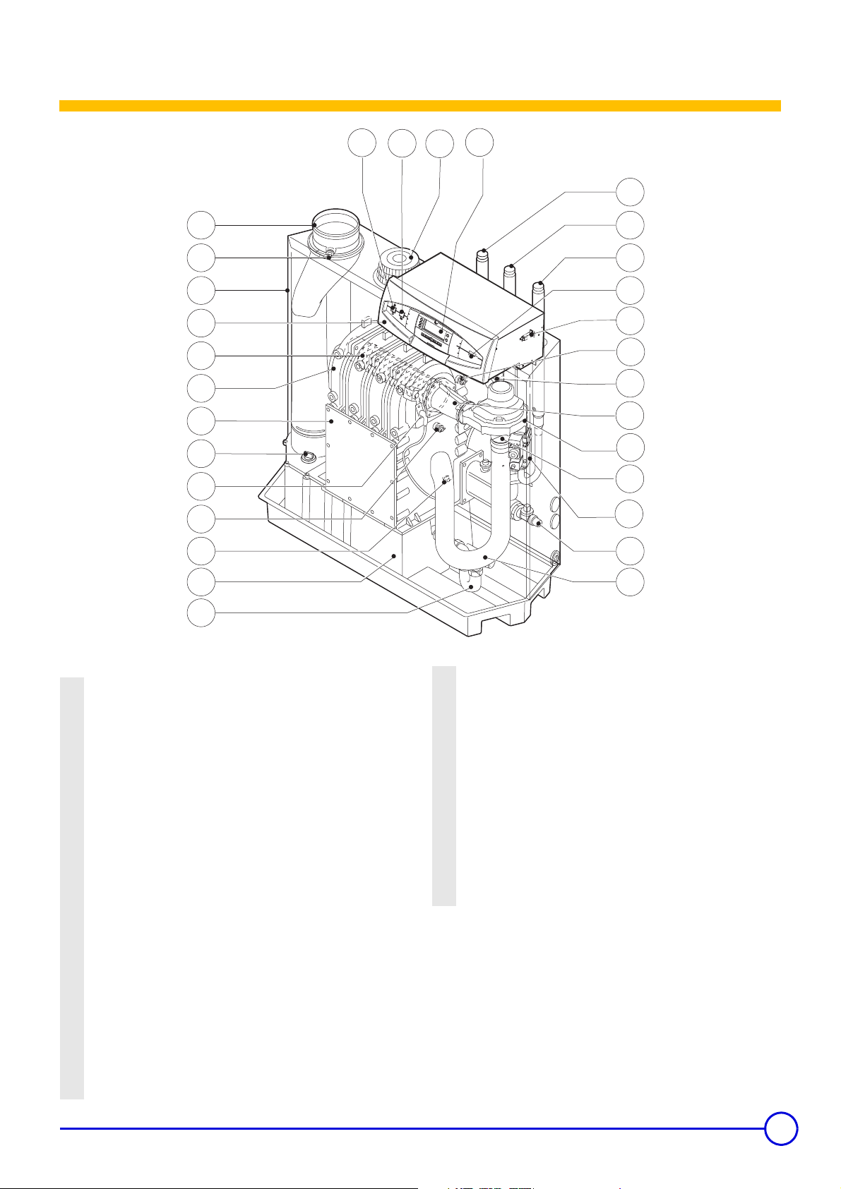
1 Flue gas discharge duct
Measurement point O
2
sensor, Option)
3 Air enclosure
4 Control panel
5 Burner
6 Heat exchanger
7 Inspection hatch
8 Inspection cap / Cleaning
9 Ignition electrode / Ionization probe
10 Heating body sensor
11 Return sensor
12 Condensates collector
13 Siphon
14 Silencer
15 Filling and emptying tap
16 Circuit breaker
17 Multivalve gas unit
18 Venturi
19 Fan
/CO2 (Emplacement for fue gas
2
0D 00658
20 Mixer pipe
21 Flue gas pressure switch
22 Output sensor
23 Connector for the programming tool
24 Gas connection
25 Return connection
26 Flow connection
27 Reset button
28 Display DIEMATIC-m3
29 Air inlet (Protective cage)
General ON
30
/ OFF 7 switch
8
20/02/09 - 300015144-001-C C 230 ECO
5
Page 6

4 Operating the appliance
4.1 Control panel
4.1.1 Control panel DIEMATIC-m3
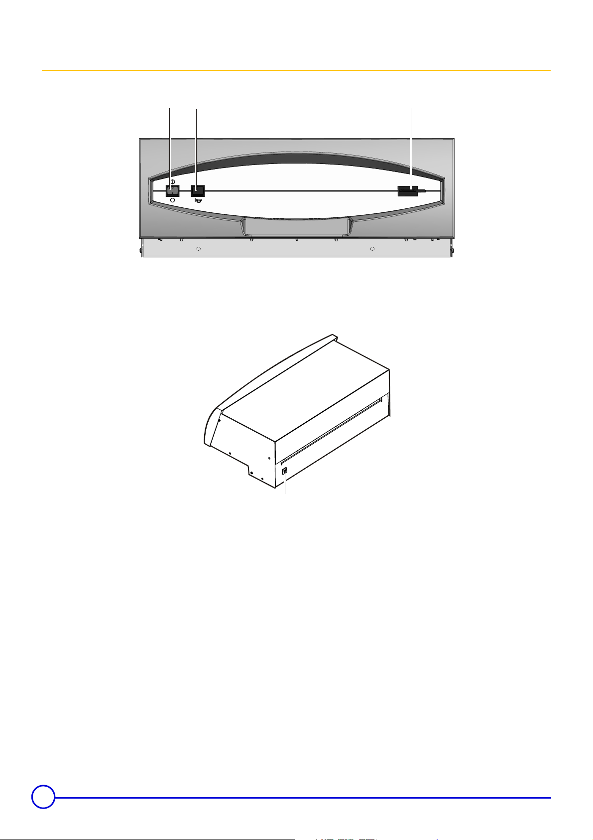
Electromechanical components
1
2
3
6
5
D000645
1. General ON 8 / OFF 7 switch
2. Reset button
3. Flap
4. Timed circuit breaker (4 A)
5. Connector for the programming tool
6. Display
6
4
The panel must always be supplied with 230V voltage:
- to ensure the anti-grip of the heating pump,
- to ensure Titan Active System® operation when a titanium anode
is protecting the DHW tank.
Furthermore, if an interactive remote control (CDI 2) is connected
and the 1 switch is in the off
the CDI 2.
See: "Control panel instructions"
Z
C 230 ECO 20/02/09 - 300015144-001-C
position, there will be no display on
7
Page 7
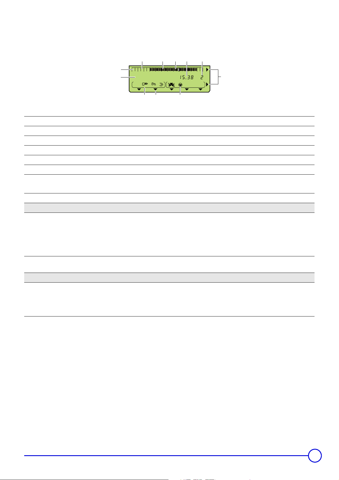
Display
3 4 5 6
2
024681012141618202224
1
SUNDAY
7
A
BC
91011
1 Text and numerical display
2 Graphic display bar for the programme in circuit A, B or C
3 Light area: Reduced temperature heating period or tank load disabled
4 Dark area: Comfort temperature heating period or tank load enabled
5 Flashing cursor showing the current time
6 Number display (current time, adjusted values, parameters, etc.)
7
8 The arrows flash when setting values can be modified using the + and - keys
9 Circuit operation symbols
>
Number of the boiler for which the parameters are displayed
Control panel instructions - See section 6.1: Access to the parameters of the slave boilers (Panel K3) in a cascade
Z
Opening the 3-way valve
8
=
:
A B C Name of the circuit displayed
10
11 Symbols indicating that the following inputs/outputs are active
#
D
Closing the 3-way valve
Displayed circuit pump on
Arrows indicating the chosen time programme (P1, P2, P3 or P4) for the circuit displayed, A, B, C, or the activation of
the manual summer mode
DHW load pump on
Summer mode (Automatic or Manual)
Burner on switch request
20/02/09 - 300015144-001-C C 230 ECO
7
Page 8
4.1.2 Control panel K3
D000645
4
1
2
3
D0006 37
1. General ON 8 / OFF 7 switch
2. Reset button
3. Connector for the programming tool
4. Timed circuit breaker (4 A)
8
C 230 ECO 20/02/09 - 300015144-001-C
Page 9

4.2 Changing the settings
4.2.1 Control panel DIEMATIC-m3
Keys accessible when the flap is closed Keys accessible when the flap is open
Adjustment keys
MODE Various operating modes can be selected by
successively pressing key MODE:
`
AUTOMATIQUE
` DAY 7/7: Forced operation at permanent Day temperature
` DAY (Until midnight): Forced operation at temporary Day
temperature
` NIGHT 7/7: Forced operation at permanent Night
temperature
` NIGHT (Until midnight): Forced operation at temporary
Night temperature
` DAYS ANTIFREEZ: Antifreeze mode for the number of
days set
` ANTIFREEZ 7/7: Permanent antifreeze mode
Restart key for a DHW calorifier load
+
AUTOMATIQUE
`
` DHW: Restarts DHW load until midnight
` DHW 7/7: DHW load is forced permanently
After a few seconds, the display disappears but the mode
is activated.
Display key for the various counters (number of burner
start-ups, number of burner operating hours, etc.)
Adjustment keys
%O
$P
STANDARD
S
J
I
*
#
K
M
Enter (per 1/2 hour) the comfort temperature
period or tank load enabled (dark area).
Enter (per 1/2 hour) the reduced temperature
period or tank load disabled (light area).
Simultaneously pressing the 2 keys,
, resets all of the time programmes.
$P
Return key
Page scrolling
Line scrolling
Scroll of boilers connected
Manual "Summer" shutdown key. The heating is
switched off and DHW production is ensured.
Fitter settings access key
Sweep key
%O
and
2%
2$
20/02/09 - 300015144-001-C C 230 ECO
Set temperatures Day (Heating / DHW / Pool)
Set temperatures Night (Heating / DHW)
Access key to the slave boilers (Panel K3) in a cascade
*
(
)
+/- Adjustment keys
If using only one boiler, this key is inactive.
Setting the gradients for circuits A, B and C
Setting the parallel offsets DECAL.// DEP.A, DECAL.//
DEP.B or DECAL.// DEP.C for the heating curves on
circuits A, B or C.
If the Day setting for one of the circuits, A, B or C, is
above 30°C, you no longer have access parallel offset on
this circuit.
Z
See Control panel instructions
9
Page 10

4.2.2 Control panel K3
Make all settings on the master boiler fitted with a DIEMATIC-m3
control panel
Press the
Access to the parameters of the slave boilers (Panel K3) in a cascade
*
key.
• Boiler temperature display on the master boiler
024681012141618202224
BOILER TEMP.
A
Number of the boiler for which the parameters are displayed
` Press the
The number of the boiler displayed corresponds to the setting
on the coding wheel.
Adjustme
nt (Code
wheel)
01
12
23
etc.
key
*
Number of the boiler for which the parameters are
displayed
Master boiler (Control panel
DIEMATIC-m3)
”Follower - 1” boiler
(Control panel K3)
”Follower - 2” boiler
(Control panel K3)
• Boiler temperature display on the slave boiler
024681012141618202224
BOILER TEMP.
A
Number of the boiler for which the parameters are displayed
All parameters and measurements on the slave boilers (Control
Panel K3) can be accessed with the control panel keys DIEMATICm3.
Key
(Control Panel K3) to the master boiler (DIEMATIC-m3 Control
Panel).
The parameters on the slave boilers can be read on the control panel
display DIEMATIC-m3.
is used to transmit all information from the slave boilers
*
If no keys are pressed for 10 seconds, the control panel display
returns to the master boiler (Number 1).
10
C 230 ECO 20/02/09 - 300015144-001-C
Page 11

4.3 Stopping the boiler
- Cut the power supply to the boiler.
- Close the gas valve.
Don't forget the risk of frost.
4.3.1 Precautions to take if there is a danger of frost
Heating circuit:
Use a correctly dosed antifreeze to prevent the heating water
freezing. If this cannot be done, drain the system completely. In all
cases, consult the fitter.
Domestic hot water circuit:
Drain the domestic water tank and pipes.
4.3.2 Precautions required in the case of long boiler stops (one or more years)
- Close the gas valve
- The boiler and the chimney must be swept carefully.
- Close the door of the boiler to prevent the internal circulation of air.
4.4 Commissioning the boiler
Initial commissioning must be done by a qualified
professional.
4.4.1 Commissioning
- Ensure that the boiler is switched off
- Remove the front casing
- Open the main gas valve
- Open the boiler control panel (Control panel instructions)
- Check the electrical connection
- Fill the installation with water and check hydraulic tightness (Pmin:
0.8 bar)
- Bleed the heating installation
- Fill the condensates siphon with water
- Check the connection of the combusted gas evacuation and the air
inlet
- Empty the gas inlet
- Open the gas valve on the gas pipe to the boiler
- Check the gas connection
- Turn the boiler on
- Turn the main switch to 8
- The boiler type is displayed on the screen for 5 seconds
- Provoke a heating request
- The boiler starts to operate
- Check the settings (See "Gas settings" - Installation and Service
Manual). If necessary, correct the settings
5 Checking and maintenance
The boiler is almost maintenance-free if it is set correctly. The boiler
only requires an annual check and cleaning if necessary.
Make the following checks at least 1 time a year:
- Checking the combustion in the boiler
- Setting the ignition electrode
- Checking tightness (hydraulics, combusted gas discharge and
gas)
- Checking the hydraulic pressure
Carry out the following maintenance at least 1 time a year:
- Clean the fan
- Clean the heat exchanger using the tool provided
- Clean the burner
- Clean the siphon.
20/02/09 - 300015144-001-C C 230 ECO
11
Page 12

6 Troubleshooting
6.1 Rating plate
D
XX-XX
12
C 230 ECO 20/02/09 - 300015144-001-C
Page 13

6.2 Messages - Faults
6.2.1 Messages
Message
Code
no.
The message SHOW REM.CTRL indicates
SHOW REM. CTRL
the presence of an override on a remote
control
REVISION Boiler service required
BL.PSU ERROR
BL.MAX BOILER
BL.MAX EXCHAN
BL.DERIVE EXCH
0
Error parameters
1
Boiler temperature > 110 °C Wait 10 minutes for the temperature to come down
3
Heat exchanger temperature > 95 °C
The speed at which the exchanger
4
temperature is rising is too high
The temperature difference between the
BL.DT EXC.BACK
5
exchanger sensor and the return sensor is
too great (35 K)
The temperature difference between the
BL.DT BOI.EXC.
6
boiler sensor and the exchanger sensor is
too great
BL.RL OPEN
8
The RL inlet on the PCU is open
- Phase and neutral inverted
9
BL.INV. L/N
- Mains electricity with floating or two-phase
neutral
11
BL.CS OPEN
BL.COM PCU-M3
BL.GAS PRESS
BL.BAD SU
BL.PCU ERROR
The contact inlet CS is open Check the cause of the open contact CS
Communication breakdown between PCU
13
and DIEMATIC-m3
15
Gas pressure too low
16
The SU is not compatible with the PCU
17
Error parameters
Probable causes Action
To cancel the overrides on all remote controls, press the
AUTO key for 5 seconds
Contact the professional responsible for maintenance of the
boiler
- Switch the boiler off and switch back on
- Set the boiler type parameter (See #CONFIGURATION)
- Wait 10 minutes for the temperature to come down
- Check the water flow
- Check that the installation and boiler are adequately filled
with water and correctly irrigated and bled
- Check: Heat exchanger fouled
- Wait 10 minutes for the temperature to come down
- Check the water flow
- Check that the installation and boiler are adequately filled
with water and correctly irrigated and bled
- Check: Heat exchanger fouled
- Wait 10 minutes for the temperature to come down
- Check the water flow
- Check that the installation and boiler are adequately filled
with water and correctly irrigated and bled
- Check: Heat exchanger fouled
- Wait 10 minutes for the temperature to come down
- Check the water flow
- Check that the installation and boiler are adequately filled
with water and correctly irrigated and bled
- Check: Heat exchanger fouled
- Switch the boiler off and switch back on
- Set the boiler type parameter (See #CONFIGURATION)
- Respect the rating plate on the connection terminal block
- Set the boiler type parameter (See #CONFIGURATION)
Check the link and the connectors
Check:
- Opening the gas valve on the boiler
- Gas supply pressure
- Correct installation of the pressure switch (Replace if
necessary)
- Switch the boiler off and switch back on
- SU: Change them
- Switch the boiler off and switch back on
- PCU: Change them
20/02/09 - 300015144-001-C C 230 ECO
13
Page 14

Message
BL.BAD PSU
BL. COM SU
BL.FLAME LOS
BL.CCE TEST
BL.SU ERROR
BL.UNKNOWN
Code
no.
18
21
22
24
25
254
Probable causes Action
The PSU is not compatible with the PCU
Communication breakdown between PCU
and SU
Flame lost
The cyclical leak proofing kit (CCE) has
detected a problem
SU: Internal error
Blockage unknown
- Switch the boiler off and switch back on
- PSU: Change them
- Set the boiler type parameter
Check the installation of the SU on the PCU
- Wait 10 seconds
- If, after 5 attempts, the error persists, BL.FLAME LOS
changes to I-CURRENT FAIL
Check:
- Opening the gas valve on the boiler
- Gas pressure
- Setting the gas valve unit
- Check the connection of the combusted gas evacuation
and the air inlet
- Checking the heat exchanger
- Wait 10 seconds
- If, after 5 attempts, the error persists, BL.CCE TEST
changes to CCE TEST FAIL
Check:
- Opening the gas valve on the boiler
- Gas pressure
- Correct installation of the pressure switch handling the
CCE function (Replace if necessary)
- Gas valve (Replace if necessary)
- Wiring
- Wait 10 seconds
- SU: Change them
- Switch the boiler off and switch back on
- SU: Change them
Messages are not memorised.
14
C 230 ECO 20/02/09 - 300015144-001-C
Page 15

6.2.2 Faults
Faults Code no. Probable causes Action
BOILER S.FAIL.
BACK S.FAILURE
EXCHAN.S.FAIL.
OUTSI. S.FAIL.
DHW S. FAILURE
AUX1.SENS.FAIL
AUX2.SENS.FAIL
UNIV.SENS.FAIL
OUTL S.A FAIL.
32 The boiler sensor is short circuited - Reset the box
33 The boiler sensor is off
6 The return sensor is short circuited - Reset the box
7 The return sensor is off
8 The sensor reading is under -10°C
2 The exchanger sensor is short circuited - Reset the box
3 The exchanger sensor is off
4 The sensor reading is under -10°C
- Check the link and the connectors
- Replace the sensor if necessary
- Check the link and the connectors
- Replace the sensor if necessary
- Check the link and the connectors
- Replace the sensor if necessary
OUTL S.B FAIL.
OUTL S.C FAIL.
ROOM S.A FAIL.
ROOM S.B FAIL.
ROOM S.C FAIL.
SWIM.P.A S.FAIL
SWIM.P.B. S.FAIL
SWIM.P.C. S.FAIL
SOLAR S. FAIL
ST.TANK S.FAIL
DHW 2 S. FAIL
BOILER 2 FAIL.
BOILER 3 FAIL.
BOILER 4 FAIL.
BOILER 5 FAIL.
BOILER 6 FAIL.
BOILER 7 FAIL.
The corresponding sensor is off or shortcircuited.
Error on a slave boiler, in a cascade
installation.
Check the link and the connectors. Replace the sensor if
necessary.
See comments below.
Press key
to see the error.
*
BOILER 8 FAIL.
BOILER 9 FAIL.
BOILER 10 FAIL.
TA-S SHORT-CIR
TA-S DISCONNEC
20/02/09 - 300015144-001-C C 230 ECO
The Titan Active System® is shortcircuited.
The Titan Active System® is on an open
circuit.
Check that the Titan Active System® is not shortcircuited.
Check that the Titan Active System® is correctly
connected.
15
Page 16

Faults Code no. Probable causes Action
- Switch off the current.
TA-S FAILURE Internal problem.
- Contact the professional responsible for maintenance of
the boiler.
- Reset the box
PSU FAIL 0 PSU not connected or faulty
- Check the link and the connectors
- PSU: Replace if necessary
- Reset the box
PSU PARAM FAIL 1 Safety parameter errors
- Check the link and the connectors
- PSU: Replace if necessary
- Reset the box
STB EXCHANGE 5 Exchanger temperature too high
- Check that the installation and boiler are adequately
filled with water and correctly irrigated and bled
- Check: Heat exchanger fouled
- Reset the box
STB BACK 9 Return temperature too high
- Check that the installation and boiler are adequately
filled with water and correctly irrigated and bled
- Check: Heat exchanger fouled
- Reset the box
- Check that the installation and boiler are adequately
filled with water and correctly irrigated and bled
Check:
- Heat exchanger fouled
- Sensor installed correctly
EXCH-BACK<MIN 10
- The temperature difference between the
exchanger sensor and the boiler flow
sensor is too little
- Sensor defective
- No flow rate or flow rate too low
- Sensor installed incorrectly
- Level differences on the temperature sensors
- Reset the box
- Check that the installation and boiler are adequately
filled with water and correctly irrigated and bled
Check:
- Heat exchanger fouled
- Sensor installed correctly
EXCH-BACK>MAX 11
- The temperature difference between the
exchanger sensor and the boiler flow
sensor is too great
- Sensor defective
- No flow rate or flow rate too low
- Sensor installed incorrectly
- Level differences on the temperature sensors
- Reset the box
- Check the wiring
- Ensure that the siphon is not empty. Top up with more
water if necessary
SMOKE.P.FAIL 12
- The flue gas pressure switch is open
- Bad connection
- The pressure in the combusted gases
evacuation duct is too high
- It is possible that the combustion products evacuation
pipe is totally or partially obstructed
- Check: Open flue damper
16
C 230 ECO 20/02/09 - 300015144-001-C
Page 17

Faults Code no. Probable causes Action
- No flame after 5 ignition attempts
- No ignition spark
- No flame after 5 ignition attempts
- No flame
BURNER FAILURE 14
- No flame after 5 ignition attempts
- Flame present (insufficient ionization)
- The cyclical leak proofing kit (CCE) has
detected a leak
CCE TEST FAIL 15
PARASIT FLAME 16 Detection of a parasite flame
VALVE FAIL 17 Gas valve defective
FAN FAILURE 34 The fan is not running at the right speed
BACK>BOIL FAIL 35
I-CURRENT FAIL 36
SU COM.FAIL 37
PCU-M3 COM.FAIL 38
The return temperature is higher than the
boiler temperature
The flame went out more than 5 times in 24
hours while the burner was operating
Communication breakdown between PCU
and SU
Communication breakdown between PCU
and DIEMATIC-m3
- Reset the box
- Check the correct connection of the ignition cable and
that there is no breakdown or short circuit on the earth
Check:
- the gap between the electrodes (3 to 4 mm)
- Burner cover status (Burner / electrode cover closed)
- Faulty control by the SU board
- Reset the box
- First check that the gas valve is open, that the gas
supply pressure is present, that the gas conduit has
been sufficiently bled, that the air/flue gas conduit is not
blocked and is not leaking, that the siphon is full and not
blocked
- The gas valve unit must be set with precaution
- Gas block: Wiring OK
-
Faulty control by the SU board
Check the correct connection of the ignition cable and that
there is no breakdown or short circuit on the earth
Check:
- Check the electrode condition
- Opening the gas valve on the boiler
- Gas supply pressure
- Reset the box
Check:
- Opening the gas valve on the boiler
- Gas supply pressure
- Replace the gas valve (If necessary)
- Reset the box
Check:
- Ignition/ionization electrode
- Leak on the gas valve
- Gas inlet valve closed (Compulsory)
- Reset the box
- Check the link and the connectors
- Check the gas valve and replace if necessary
- Reset the box
Check:
- Cabling error
- Fan error
- Reset the box
- Check the water circulation direction in the boiler
- Check that the boiler sensor and the return sensor have
not been reversed
- Reset the box
Check:
- Gas supply pressure
- Pressure regulator
- Setting the gas valve unit
- Reset the box
- Check the installation of the SU on the PCU
- Reset the box
- Check the link and the connectors
20/02/09 - 300015144-001-C C 230 ECO
17
Page 18

Faults Code no. Probable causes Action
CS OPEN FAIL 39 The contact inlet CS is open
FAIL. UNKNOWN 254 Fault unknown
PCU COM. FAIL
Communication breakdown between
DIEMATIC-m3 and PCU
5 RESET:ON/OFF 5 resets done in less than an hour
Communication error between DIEMATIC
MC COM.FAIL
M3 and the boiler module for the CDI radio
(CDR)
- Check the cause of the open contact CS
- Reset the box
- Switch the boiler off and switch back on
- SU: Change them
- Reset the box
- Check the link and the connectors
- Switch the boiler off and switch back on
- Switch the boiler off and switch back on. The current
error is displayed and can be reset
- Check the link between the DIEMATIC M3 and the boiler
module
18
C 230 ECO 20/02/09 - 300015144-001-C
Page 19

Comments
OUTSI. S.FAIL. The boiler operates on BOILER MAX temperature
- The valve setting is no longer ensured but monitoring the maximum
temperature of the circuit after the valve is ensured.
- Valves may be manually operated.
- Reheating the domestic hot water remains ensured.
DHW S. FAILURE The hot water storage tank reheating operation is no longer assured.
OUTL S.A FAIL., OUTL S.B FAIL. and OUTL S.C FAIL. The circuit concerned goes from automatic to manual mode: The pump
operates.
ROOM S.A FAIL., ROOM S.B FAIL. and ROOM S.C FAIL. The circuit concerned operates without any influence from the room sensor.
SWIM.P.A S.FAIL, SWIM.P.B. S.FAIL, SWIM.P.C. S.FAIL Pool reheating is independent of its temperature.
SOLAR S. FAIL Reheating domestic hot water using the solar panel is no longer ensured.
ST.TANK S.FAIL The hot water storage tank reheating operation is no longer assured.
TAS... Domestic hot water production is shut down and can be restarted using key
.
The tank is no longer protected.
Contact the professional responsible for maintenance of the
boiler.
A tank without Titan Active System® is connected to the boiler: Check
that the Titan Active System® simulation connector (delivered with
package AD212) is fitted to the sensor card."
The last ten failures are memorised in the paragraph #DEF.
HISTORY
See: "Parameter and input/output check (mode tests) - Control
Z
panel instructions
20/02/09 - 300015144-001-C C 230 ECO
19
Page 20

6.3 Technical characteristics
C 230-... Unit 85 130 170 210
General
Number of sections 3456
Burner operation Modulating
Useful output (80/60°C) PN (G20)
Useful output (50/30°C) PN (G20)
Burner output (PCI) (G20)
Combustion gas and by-products
Gas supply pressure G20 mbar 17 - 30
Gas flow rate G20 (15 °C - 1013 mbar)
Gas flow rate G25 (15 °C - 1013 mbar)
Gas flow rate G27 (15 °C - 1013 mbar)
Gas flow rate G31
(G20-G25) Qmin.-Qmax (Open air box) % 9.3-8.8 9.3-8.8 9.3-8.8 9.3-8.8
CO
2
CO
(G20-G25) Qmin.-Qmax (Closed air box) % 9.5-9.0 9.5-9.0 9.5-9.0 9.5-9.0
2
CO
(G27) Qmin.-Qmax (Open air box) % 9.3-8.8 9.3-8.8 9.3-8.8 -
2
CO
(G27) Qmin.-Qmax (Closed air box) % 9.5-9.0 9.5-9.0 9.5-9.0 -
2
CO
(G31) Qmin.-Qmax (Open air box) % 10.5-9.8 10.5-9.8 10.5-9.8 10.5-9.8
2
CO
(G31) Qmin.-Qmax (Closed air box) % 10.7-10.0 10.7-10.0 10.7-10.0 10.7-10.0
2
Average nitrogen oxide emission (NOx) mg/kWh 62 54 49 58
Average CO emission mg/kWh 19 15 16 19
Maximum pressure at the flue gas nozzle Pa 130 130 130 130
Combusted gas flow
(2)
Classification of type according to the discharge of
combusted gases and air supply
Heating
Safety temperature °C 110
Water setting range °C 20 - 90
Water pressure
Water content l 12 16 20 24
Water resistance at
Water resistance at
∆T = 10K
∆T = 20K
Electricity characteristics
Power supply voltage V/Hz 230 / 50
minimumkW16222939
maximum kW 87
113
(1)
/120
166 200
minimumkW18243344
maximum kW 93
121
(1)
/129
179 217
minimumkW17233141
maximum kW 89
minimum
maximum
minimum
maximum
minimum
maximum
3
m
/h
3
m
/h
3
/h
m
3
m
/h
3
/h
m
3
m
/h
1.8 2.4 3.3 4.3
9.4
2.1 2.8 3.8 5.0
11 14.4 20.9 25.2
2.2 3.0 4.0 -
11.5 15.9 22.0 -
115
12.2
(1)
(1)
/123
/13
170 205
18 21.7
minimum Kg/h 1.94 1.94 3.42 3.19
maximum Kg/h 6.91 9.56 13.21 15.93
minimum Kg/h 27.2 36.7 49.5 65.5
maximum Kg/h 149.7
193.5
206.9
286.0 344.9
(1)
/
B23, B23P, C13, C33, C43, C53, C63, C83
minimum bar 0,8
maximum bar 6
mbar 660 540 680 720
mbar 165 135 170 180
20
C 230 ECO 20/02/09 - 300015144-001-C
Page 21

C 230-... Unit 85 130 170 210
Power consumption (Panel DIEMATIC M3
Insulation class IP 21
Miscellaneous
Weight without water kg 130 150 170 200
Acoustic level at 1 meter dBA
(1) For Italy
(2) G20 - Gas H
minimum W 34 36 56 59
maximum W 125 193 206 317
≤ 57 ≤ 63
7 Energy savings
Here are a few tips for saving energy:
- Install reflector panels behind the radiators.
- Do not cover the radiators. Do not hang curtains in front of the
radiators.
- Insulate pipes to prevent thermal losses and condensation.
- Do not obstruct aeration grates (even partially). They help to
reduce humidity in the home. The more humid a home, the more
heating it consumes.
- Turn heating off when airing a room (5 minutes a day is sufficient)
Avoid deregulating the thermostat. Place the start/stop switch on
Off.
- Do not shut down heating completely if you are absent. Lower the
thermostat by 3-4°C.
- Use the sun's heat as much as possible.
- Take showers rather than baths. Use a water-saving shower head.
20/02/09 - 300015144-001-C C 230 ECO
21
Page 22

Warranty
You have just purchased one of our appliances and we thank you
for the trust you have placed in our products.
Please note that your appliance will provide good service for a
longer period of time if it is regularly checked and maintained.
Your fitter and our customer support network are at your disposal
at all times.
Warranty terms
Starting from the purchase date shown on the original fitter's
invoice, your appliance has a contractual guarantee against any
manufacturing defect.
The length of the guarantee is mentioned in the price catalogue.
The manufacturer is not liable for any improper use of the
appliance or failure to maintain or install the unit correctly (the
user shall take care to ensure that the system is installed by a
qualified fitter).
In particular, the manufacturer shall not be held responsible for
any damage, loss or injury caused by installations which do not
comply with the following:
- applicable local laws and regulations
- specific requirements relating to the installation, such as
national and/or local regulations
- the manufacturer's instructions, in particular those relating to
the regular maintenance of the unit
- the rules of the profession
France
The preceding dispositions are not exclusive of benefits for the
purchaser of the legal guarantee as stated in Civil Code articles
1641 to 1648.
Belgium
The preceding dispositions about the contractual guarantee are
not exclusive of profit if the need arises for the purchaser in
Belgium of the applicable legal dispositions on hidden defects.
Switzerland
The application of the warranty is subject to the terms and
conditions of sale, delivery and warranty of the company
marketing our products.
Poland
Warranty conditions are included in the warranty card.
Other countries
The above provisions do not restrict the benefit of the legal laws
regarding hidden defects applicable in the buyer's country.
The warranty is limited to the exchange or repair of such parts as
have been recognised to be faulty by our technical department
and does not cover labour, travel and carriage costs.
The warranty shall not apply to the replacement or repair of parts
damaged by normal wear and tear, negligence, repairs by
unqualified parties, faulty or insufficient monitoring and
maintenance, faulty power supply or the use of unsuitable fuel.
Sub-assemblies such as motors, pumps, electric valves etc. are
guaranteed only if they have never been dismantled.
22
C 230 ECO 20/02/09 - 300015144-001-C
Page 23

20/02/09 - 300015144-001-C C 230 ECO
23
Page 24

FR
DE DIETRICH THERMIQUE S.A.S.
www.dedietrich-thermique.fr
Direction des Ventes France
57, rue de la Gare
F- 67580 MERTZWILLER
+33 (0)3 88 80 27 00
+33 (0)3 88 80 27 99
DE
BE
CN
DE DIETRICH REMEHA GmbH
www.dedietrich-remeha.de
Rheiner Strasse 151
D- 48282 EMSDETTEN
+49 (0)25 72 / 23-5
+49 (0)25 72 / 23-102
info@dedietrich.de
VAN MARCKE
www.vanmarcke.be
Weggevoerdenlaan 5
B- 8500 KORTRIJK
+32 (0)56/23 75 11
DE DIETRICH
www.dedietrich-heating.com
Room 512, Tower A, Kelun Building
12A Guanghua Rd, Chaoyang District
C-100020 BEIJING
+86 (0)106.581.4017
+86 (0)106.581.4018
+86 (0)106.581.7056
+86 (0)106.581.4019
contactBJ@dedietrich.com.cn
LU
RU
AT
NEUBERG S.A.
www.dedietrich-heating.com
39 rue Jacques Stas
L- 2010 LUXEMBOURG
+352 (0)2 401 401
DE DIETRICH
www.dedietrich-otoplenie.ru
Россия
109044 г. Москва
ул. Крутицкий Вал, д. 3
корп. 2, оф. 35
+7 495 988-43-04
+7 495 988-43-04
dedietrich@nnt.ru
ÖAG AG
www.oeag.at
Schemmerlstrasse 66-70
A-1110 WIEN
+43 (0)50406 - 61624
+43 (0)50406 - 61569
dedietrich@oeag.at
CH
WALTER MEIER (Klima Schweiz) AG
www.waltermeier.com
Bahnstrasse 24
CH-8603 SCHWERZENBACH
+41 (0) 44 806 44 24
Serviceline +41 (0)8 00 846 846
+41 (0) 44 806 44 25
ch.klima@waltermeier.com
WALTER MEIER (Climat Suisse) SA
www.waltermeier.com
Z.I. de la Veyre B, St-Légier
CH-1800 VEVEY 1
+41 (0) 21 943 02 22
Serviceline +41 (0)8 00 846 846
+41 (0) 21 943 02 33
ch.climat@waltermeier.com
© Copyright
All technical and technological information contained in these technical instructions, as well as any
drawings and technical descriptions supplied, remain our property and shall not be multiplied
without our prior consent in writing.
Subject to alterations.
20/02/09
AD001NU-AB
DE DIETRICH THERMIQUE
57, rue de la Gare F- 67580 MERTZWILLER - BP 30
 Loading...