

Page 1
UNO
L000541-B
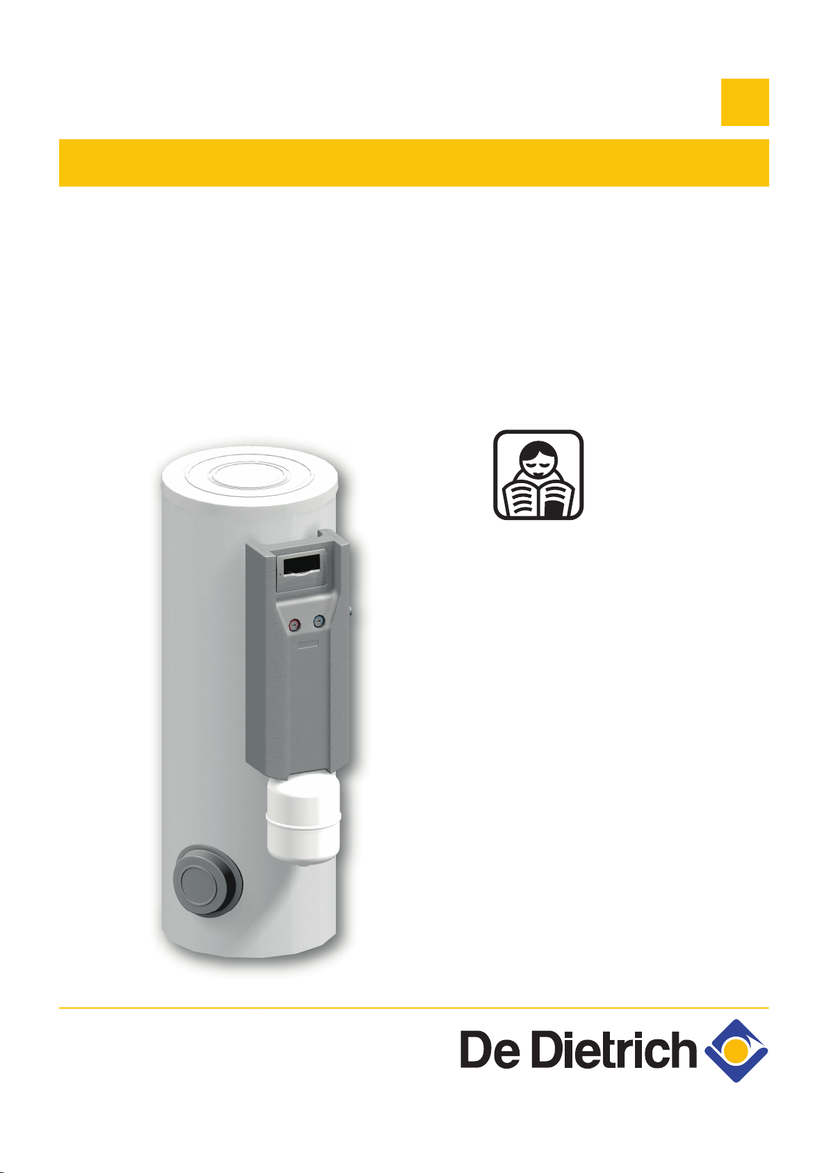
Solar hot water calorifer
BSL 150...400
BESL 200...400
EN
User Guide
300028413-001-02
Page 2

Contents
1 Introduction ................................................................................................4
1.1 Symbols used .......................................................4
1.1.1 Symbols used in the manual ...................................4
1.1.2 Symbols used on the equipment .............................4
1.2 Abbreviations ........................................................4
1.3 General ..................................................................5
1.3.1 Manufacturer’s liability .............................................5
1.3.2 Installer’s liability .....................................................5
1.3.3 User’s liability ..........................................................5
1.4 Homologations ......................................................6
1.4.1 Certifications ...........................................................6
2 Safety instructions and recommendations ..............................................7
2.1 Safety instructions ...............................................7
2.2 Recommendations ................................................7
3 Technical description ................................................................................9
3.1 Solar domestic hot water calorifier .....................9
3.2 Control panels .....................................................10
3.2.1 Description of the keys ..........................................10
3.2.2 Description of the display ......................................11
4 Operating the appliance ..........................................................................13
4.1 Reading out measured values ...........................13
4.1.1 Resetting the values to zero ..................................13
4.2 User settings .......................................................14
4.2.1 Setting the time .....................................................14
4.2.2 Force back-up .......................................................14
4.2.3 Modifying the back-up authorisations ....................14
4.2.4 In the event of prolonged absences ......................14
4.3 Setting the DHW calorifier outlet
temperature .........................................................15
4.3.1 Programming and setting the electrical back-
up ..........................................................................15
4.3.2 Setting the thermostatic mixing valve ....................16
1
14/10/2013 - 300028413-001-02
Page 3

Contents
4.4 Starting and stopping the control system ........16
5 Checking and maintenance .....................................................................17
5.1 General instructions ...........................................17
5.2 Safety valve or safety unit .................................17
5.3 Cleaning the casing material .............................17
5.4 Checking the magnesium anode .......................17
6 Troubleshooting .......................................................................................18
6.1 Incidents and solutions ......................................18
7 Technical specifications ..........................................................................19
7.1 Solar domestic hot water calorifier ...................19
7.2 Composition of the NF CESI solar systems
packages (For France) .......................................20
8 Warranty ....................................................................................................23
8.1 General ................................................................23
8.2 Warranty terms ...................................................23
2
14/10/2013 - 300028413-001-02
Page 4

3
14/10/2013 - 300028413-001-02
Page 5
BSL 150...400 BESL 200...400
1 Introduction
1.1 Symbols used
1. Introduction
1.1.1. Symbols used in the manual
In these instructions, various danger levels are employed to draw the
user’s attention to particular information. In so doing, we wish to
safeguard the user’s safety, obviate hazards and guarantee correct
operation of the appliance.
DANGER
Risk of a dangerous situation causing serious physical
injury.
WARNING
Risk of a dangerous situation causing slight physical
injury.
CAUTION
Risk of material damage.
Signals important information.
¼Signals a referral to other instructions or other pages in the
instructions.
1.1.2. Symbols used on the equipment
Before installing and commissioning the device, read
carefully the instruction manuals provided.
Dispose of the used products in an appropriate recovery
and recycling structure.
1.2 Abbreviations
14/10/2013 - 300028413-001-02
4 CFC: Chlorofluorocarbon
4 DHW: Domestic hot water
4
Page 6

1. Introduction
1.3 General
BSL 150...400 BESL 200...400
1.3.1. Manufacturer’s liability
Our products are manufactured in compliance with the requirements
of the various applicable European Directives. They are therefore
delivered with [ marking and all relevant documentation.
In the interest of customers, we are continuously endeavouring to
make improvements in product quality. All the specifications stated in
this document are therefore subject to change without notice.
Our liability as the manufacturer may not be invoked in the following
cases:
4 Failure to abide by the instructions on using the appliance.
4 Faulty or insufficient maintenance of the appliance.
4 Failure to abide by the instructions on installing the appliance.
1.3.2. Installer’s liability
The installer is responsible for the installation and inital start up of the
appliance. The installer must respect the following instructions:
4 Read and follow the instructions given in the manuals provided
with the appliance.
4 Carry out installation in compliance with the prevailing legislation
and standards.
4 Perform the initial start up and carry out any checks necessary.
4 Explain the installation to the user.
4 If a maintenance is necessary, warn the user of the obligation to
check the appliance and maintain it in good working order.
4 Give all the instruction manuals to the user.
1.3.3. User’s liability
To guarantee optimum operation of the appliance, the user must
respect the following instructions:
4 Read and follow the instructions given in the manuals provided
with the appliance.
4 Call on qualified professionals to carry out installation and initial
start up.
4 Get your installer to explain your installation to you.
4 Have the required checks and services done.
4 Keep the instruction manuals in good condition close to the
appliance.
5
14/10/2013 - 300028413-001-02
Page 7

BSL 150...400 BESL 200...400 1. Introduction
This appliance is not intended to be used by persons (including
children) whose physcial, sensory or mental capacity is impaired or
persons with no experience or knowledge, unless they have the
benefit, through the intermediary of a person responsible for their
safety, of supervision or prior instructions regarding use of the
appliance. Care should be taken to ensure that children do not play
with the appliance.
To prevent hazardous situations from arising, if the mains lead is
damaged it must be replaced by the original manufacturer, the
manufacturer’s dealer or another suitably skilled person.
1.4 Homologations
1.4.1. Certifications
This product complies to the requirements to the european directives
and following standards:
4 2006/95/EC Low Voltage Directive.
Reference Standard: EN 60.335.1.
4 2004/108/EC Electromagnetic Compatibility Directive.
Reference Standards: EN 50.081.1, EN 50.082.1, EN 55.014
14/10/2013 - 300028413-001-02
6
Page 8
2. Safety instructions and recommendations
2 Safety instructions and
recommendations
2.1 Safety instructions
DANGER
If smoke is released or in case of refrigerant leak:
1. Switch the appliance off.
2. Open the windows.
3. Evacuate the premises.
4. Contact a qualified professional.
BSL 150...400 BESL 200...400
2.2 Recommendations
CAUTION
Do not neglect to service the appliance. Contact a qualified
professional or take out a maintenance contract for the
annual servicing of the appliance.
CAUTION
Before any work, switch off the mains supply to the
appliance.
WARNING
Only qualified professionals are authorised to work on the
appliance and the installation.
Never drain the installation. Do not replace or add water
or solar fluid to the installation. These actions must be
carried out by a qualified technician
To take advantage of the guarantee, no modifications must be made
to the appliance. Only remove the covers for maintenance and
breakdown repair operations and put the covers back in place after
the maintenance and breakdown repair operations.
Instructions stickers
The instructions and warnings affixed to the appliance must never be
removed or covered and must remain legible during the entire lifespan
of the appliance. Immediately replace damaged or illegible
instructions and warning stickers.
7
14/10/2013 - 300028413-001-02
Page 9
BSL 150...400 BESL 200...400 2. Safety instructions and recommendations
WARNING
Never cut the power to the solar control system, even
during extended absences. The control system protects
the installation against overheating in summer when it is
running.
WARNING
Do not modify the control system parameters unless fully
conversant with them.
During extended absences, we recommend lowering the set point
temperature in the solar DHW calorifier to 45°C. When the user is
present, the set point must be set to 60°C.
14/10/2013 - 300028413-001-02
8
Page 10

2
1
4
5
3
MW-2000006-01
L000430-C
5
7
4
6
1
2
3
3. Technical description BSL 150...400 BESL 200...400
3 Technical description
3.1 Solar domestic hot water calorifier
BSL 150
A
Z
E
R
T
BSL 200...400
A
Z
E
R
T
Y
U
Top inspection trap
Solar regulator
Safety control unit for the solar circuit
Side inspection plate
Expansion vessel
Expansion vessel
Top inspection trap
Side inspection plate
Solar station
Solar regulator
Electrical back-up (Option)
Safety control unit for the solar circuit
All components are checked for leaks and tested in the
factory. The control system, the pump and the electrical
back-up are pre-wired.
9
14/10/2013 - 300028413-001-02
Page 11

L000431-C
2
3
5
4
6
1
7
M002759-A
A
B
C
D
BSL 150...400 BESL 200...400 3. Technical description
BESL 200...400
3.2 Control panels
A
Z
E
R
T
Y
U
Expansion vessel
Top inspection trap
Side inspection plate
Solar station
Solar regulator
Electrical back-up
Safety control unit for the solar circuit
All components are checked for leaks and tested in the
factory. The control system, the pump and the electrical
back-up are pre-wired.
3.2.1. Description of the keys
A
B
C
D 3-position switch:
Key ):
4 Move the cursor upwards.
4 Increase the value of parameter .
Key B:
4 Access a selected parameter.
4 Confirm a value modification.
Key (:
4 Move the cursor downwards.
4 Reduce the parameter value.
4 E: The back-up may be active in day mode and night
mode.
4 0: The back-up is deactivated.
4 Z: The back-up is active in night mode only.
14/10/2013 - 300028413-001-02
10
Page 12

M002760-A
1
4 5
2
3
7
8
6
M002761-A
II I
3. Technical description BSL 150...400 BESL 200...400
3.2.2. Description of the display
System schematics (System-Screen)
n
A
Z
E
R
T
Y
U
I
Operating indicators
n
Steady symbol
K
%
Z
K
E
K
T
] a
R + K a
R + %
Solar sensor probe
Solar collectors
Solar circulation pump
Solar exchanger
Solar hot water calorifer
Solar sensor
Back-up (except BSL 150)
DHW sensor - Back-up
Flashing
symbol
Z
E
E
aZ
a
T
a
State
Solar pump activated.
Back-up activated.
DHW calorifer set point temperature
exceeded.
Cooling function of the collector or
DHW calorifer activated.
Antifreeze function activated.
Antifreeze function active (running).
Minumum collector temperature
exceeded.
Maximum DHW tank temperature
exceeded.
Maximum collector temperature
exceeded.
Adjustment parameter.
Changing the settings.
Sensor fault.
Forcing of the solar pump.
Forcing the additional heating.
11
14/10/2013 - 300028413-001-02
Page 13

M002762-A
A
BSL 150...400 BESL 200...400 3. Technical description
LED display
n
A
LED message
code
Continuously
green
Green/red
flashing
Red flashing
LED
Heating pump status Description
Pump relay is closed. Regulation operating normally
(System Operating).
4 Initialisation
phase
4 Manual mode
4 Sensor fault.
4 Maximum tank
temperature
exceeded.
4 The installation is in
manual mode: Set the
regulator to automatic
mode.
4 The hot water tank has
reached the set
temperature and the
installation is in
overheating safety mode
or in cooling mode.
4 There is a sensor fault.
14/10/2013 - 300028413-001-02
12
Page 14

4. Operating the appliance BSL 150...400 BESL 200...400
4 Operating the appliance
4.1 Reading out measured values
Scroll down the values measured using the ( and ) keys.
Parameter Description Remarks
TC
TR
THR
PC %
tc
RAP
h P1
KWh
MWh
HRE
Collector temperature S1 sensor.
The value TC shows the temperature in °C given by the collector sensor in real time.
Calorifier temperature
(Solar exchanger lower)
Calorifier temperature
(Back-up)
Pump regime Value PC % gives the solar heating pump regime in real time (0-100%).
Auto-calibration time The value tc shows the self-calibration phase time remaining in seconds.
Force back-up On: Back-up powered up.
S2 sensor.
The value TR shows the temperature in °C in real time measured by the sensor in the lower
zone of the DHW calorifier.
S3 sensor.
The value THR shows the temperature in °C in real time measured by the sensor in the
upper zone of the DHW tank.
AUTO: Back-up managed by the control system.
¼See chapter: "Force back-up", page 14.
Hour run meter on the
solar pump
Amount of heat (kWh)
Amount of heat
(MWh)
Reset to zero possible.
¼See chapter: "Resetting the values to zero", page 13.
4 The amount of heat received is calculated according to the parameters input on
commissioning (DMAX).
4 Reset to zero possible.
¼See chapter: "Resetting the values to zero", page 13.
Values KWh or MWh give an estimate of the total amount of heat produced by the
installation in kWh or MWh since commissioning of the control system. The amount of heat
received is calculated according to the parameters input on commissioning (DMAX).
Time
¼See chapter: "Setting the time", page 14.
13
4.1.1. Resetting the values to zero
It is possible to reset the value to zero when the symbol T is
displayed.
1. Select a value using the ( and ) keys.
2. Press the B key for 2 seconds. The value is reset to zero.
To suspend the operation, do not press any keys for 5
seconds. The control system will automatically go back to
the value display mode.
14/10/2013 - 300028413-001-02
Page 15

M002763-A
BSL 150...400 BESL 200...400
4.2 User settings
4. Operating the appliance
4.2.1. Setting the time
1. Select the HRE channel with the ( and ) keys.
2. Press the B key for 2 seconds.
3. Set the hour with the ( and ) keys.
4. Press the B key to confirm.
5. Set the minutes with the ( and ) keys.
6. Press the B key to confirm.
CAUTION
The controller does not switch between summer and
winter time.
4.2.2. Force back-up
1. Select the RAP channel with the ( and ) keys.
2. Press the B key for 2 seconds. The symbol T flashes.
3. Set the RAP parameter to ON using the ) key.
4. Press the B key to confirm the setting.
The electrical back-up shuts down when the set point
temperature is attained.
4.2.3. Modifying the back-up authorisations
Throw the switch to modify the electrical back-up authorisations.
E
Winter: Electrical back-up is authorised day and night.
0 Electrical back-up is not authorised. No back-up heating.
Z
Summer: Electrical back-up is only authorised at night.
The back-up is deactivated if the solar pump is running.
14/10/2013 - 300028413-001-02
4.2.4. In the event of prolonged absences
In the event of prolonged absence, shut down the electrical back-up
if the function is activated and reduce the setpoint of the solar DHW
tank:
14
Page 16

I
M002799-A
4. Operating the appliance
BSL 150...400 BESL 200...400
1. Set the 3-position switch to 0.
2. Go forward to the last display channel (HRE) with the ( key.
3. Press the ( key for 5 seconds.
A setting parameter is displayed, with the symbol T.
4. Select parameter SX using keys ) and (.
5. Briefly press the B key.
The symbol T flashes, the parameter can be set.
6. Modify the parameter using the ( and ) keys.
For example 45(°C).
7. Press B to confirm the setting.
Return from prolonged absence
n
On return from a prolonged absence:
4 Adjust the set point of the solar calorifier SX to its installation value.
4 Re-authorise the back-ups.
4 Set the 3-position switch to winter or summer, according to the
season.
4.3 Setting the DHW calorifier outlet temperature
4.3.1. Programming and setting the electrical
back-up
The temperature of the volume of water heated by the electrical
resistor is set by the installer on commissioning of the installation
according to the size of the home.
Using the solar control system, it is possible to adjust the volume of
water heated to 40 °C by the resistor in two ways:
4 Force the continuous heating of the resistor for significant
unforeseen needs.
¼See chapter: "Force back-up", page 14.
4 Select winter mode w (2 hours maximum according to the volume
of the domestic hot water required at 40 °C) to compensate for the
lack of sun in winter. If necessary, the period scheduled outside of
the off-peak hours is set between 16:00 and 18:00, i.e at the end
of the day when the solar contribution is reduced and just before
the drawing off period.
¼See chapter: "Modifying the back-up authorisations", page
14.
15
14/10/2013 - 300028413-001-02
Page 17

C003732-A
57
28
BSL 150...400 BESL 200...400 4. Operating the appliance
4.3.2. Setting the thermostatic mixing valve
28
57
Domestic cold water inlet
Domestic hot water outlet
The mixing valve is set in the factory for a DHW outlet temperature of
60°C (position 6). To lower this temperature, remove the top cover
and turn the wheel anti-clockwise. In position 1, the outlet temperature
is lowered to 35°C.
Position 1 2 3 4 5 6
Temperature at the mixer valve outlet 35 °C 40 °C 45 °C 50 °C 55 °C 60 °C
4.4 Starting and stopping the control system
CAUTION
If the temperature in the solar collectors is higher than
130°C, the control system operates in safety mode. Wait
until the evening before start-up or cool down (cover) the
solar collectors.
Commissioning is performed by the installer. Once connected to the
power supply, the control system is in automatic mode. To initiate the
solar pump, a minimum temperature of 30 °C is required at the
collector and a temperature difference of 6 °C with respect to the
domestic hot water calorifier.
If the particular conditions make it necessary to adjust the
settings, contact the installer.
14/10/2013 - 300028413-001-02
16
Page 18

5. Checking and maintenance
5 Checking and maintenance
5.1 General instructions
CAUTION
4 Maintenance operations must be done by a qualified
engineer.
4 Only original spare parts must be used.
5.2 Safety valve or safety unit
The safety valve or unit on the domestic cold water inlet must be
operated at least once a month to ensure proper operating and to
prevent from any overpressure which may that may damage the
domestic hot water calorifier.
BSL 150...400 BESL 200...400
5.3 Cleaning the casing material
Clean the outside of appliances using a damp cloth and a mild
detergent.
5.4 Checking the magnesium anode
The magnesium anode must be checked at least every 2 years. After
the first check, determine the frequency of future checks on the basis
of anode wear.
WARNING
Failure to abide by this maintenance rule may damage the
domestic hot water calorifier and void its warranty.
17
14/10/2013 - 300028413-001-02
Page 19

BSL 150...400 BESL 200...400 6. Troubleshooting
6 Troubleshooting
6.1 Incidents and solutions
Description Checks Solutions
The indicator light is off. The current has been cut. Restore the current.
14/10/2013 - 300028413-001-02
18
Page 20

7. Technical specifications BSL 150...400 BESL 200...400
7 Technical specifications
7.1 Solar domestic hot water calorifier
Primary circuit: Solar exchanger
Maximum operating temperature °C 110 110 110 110
Maximum operating pressure bar (MPa) 10 (1) 10 (1) 10 (1) 10 (1)
Exchanger capacity litres 4.5 5.6 8.1 10.1
Exchange surface
Primary circuit: Back-up exchanger
Maximum operating temperature °C - 110 110 110
Maximum operating pressure bar (MPa) - 10 (1) 10 (1) 10 (1)
Exchanger capacity litres - 5.1 5.1 5.1
Exchange surface
Pressure drop at 2 m3/Time
Secondary circuit (domestic water)
Maximum operating temperature °C 95 95 95 95
Maximum operating pressure bar (MPa) 10 (1) 10 (1) 10 (1) 10 (1)
Water content litres 150 225 300 395
Top up volume litres - 75 105 150
Solar volume litres 150 150 195 245
Weight
Gross weight kg 90 125 125 158
Net weight kg 74 109 111.5 145
Performance Primary circuit: Back-up exchanger
Power exchanged
Performance
Flow per hour (∆T = 35 °C
Transfer capacity over 10 minutes (∆T = 30°C)
Cooling constant Cr Wh/24h·L·K 0.24 0.23 0.20 0.18
Maintenance consumption (ΔT=45K) kWh/24h 1.4 1.8 2.2 2.6
Performance N
(1) Primary temperature: 80 °C - Domestic cold water inlet: 10 °C - Domestic hot water outlet: 45 °C - Primary flow rate: 2 m3/h
(2) Primary temperature: 80 °C - Domestic cold water inlet: 10 °C - Domestic hot water outlet: 40 °C - Domestic hot water storage: 65 °C
(1)
(1)
(2)
L
2
m
2
m
kPa - 4 4 4
kW - 24 24 24
litres per hour - 590 590 590
litres per 10 min. - 150 200 270
BSL 150 BSL 200 BSL 300 BSL 400
0.67 0.84 1.2 1.5
- 0.76 0.76 0.76
— 0.7 1.2 2.7
Primary circuit: Solar exchanger
Maximum operating temperature °C 110 110 110
Maximum operating pressure bar (MPa) 10 (1) 10 (1) 10 (1)
Exchanger capacity litres 5.6 8.1 10.1
Exchange surface
Secondary circuit (domestic water)
Maximum operating temperature °C 95 95 95
Maximum operating pressure bar (MPa) 10 (1) 10 (1) 10 (1)
19
2
m
BESL 200 BESL 300 BESL 400
0.84 1.2 1.5
14/10/2013 - 300028413-001-02
Page 21

BSL 150...400 BESL 200...400 7. Technical specifications
Water content litres 225 300 395
Top up volume (Electric) litres 95 135 170
Solar volume litres 130 165 225
Weight
Gross weight kg 115 114 138
Net weight kg 100 102 126
Performance
Cooling constant Cr Wh/24h·L·K 0.23 0.20 0.18
Maintenance consumption (ΔT=45K) kWh/24h 1.8 2.2 2.6
BESL 200 BESL 300 BESL 400
7.2 Composition of the NF CESI solar systems packages (For France)
Check the composition of the NF CESI solar system package against
the table below. The references and packages listed must be shown
on the invoice for the system sold by the installer.
A system is complete and functional according to the NF CESI mark
if all system references appear on the invoice. The system is
composed of the following elements:
CESI System
INISOL
UNO NE 200 - 2
(1 collector)
UNO NE 200 - 4
(2 collectors)
4 A collector field with 1,2 or 3 solar collectors.
4 A solar calorifier for domestic hot water consists of a solar station,
a heating pump, an expansion vessel and a control system.
4 The solar fluid that protects the installation from frost and
corrosion.
The system is delivered to the installer in two units: a roof pack
containing the collectors, their mounting system and the hydraulic
connections on the one hand, and a cellar pack containing the
calorifier, the system components and the solar fluid on the other
hand.
Array of collectors Domestic hot water production Solar fluid
Type of
mounting
On roof
Roof-integral
Installation
(>20°)
Roof-integral
Installation (17°)
On roof
Roof-integral
Installation
(>20°)
Roof-integral
Installation (17°)
package /
Reference
ER 152
100014074
ER 153
100014075
ER 230
100014740
ER 154
100014076
ER 155
100014077
ER 231
100014741
DHW
calorifier
type/Model
BESL 200
BESL 200
package /
Reference
ER 372
100019140
ER 372
100019140
Volume
(litres)
200 Electric
200 Electric
Back-up package /
Reference
EG 101
89807794
EG 101
89807794
14/10/2013 - 300028413-001-02
20
Page 22

7. Technical specifications BSL 150...400 BESL 200...400
CESI System
INISOL
UNO NE 300 - 4
(2 collectors)
UNO NE 300 - 6
(3 collectors)
UNO NE 400 - 4
(2 collectors)
UNO NE 400 - 6
(3 collectors)
UNO N 200 - 2
(1 collector)
UNO N 200 - 4
(2 collectors)
UNO N 300 - 4
(2 collectors)
Array of collectors Domestic hot water production Solar fluid
Type of
mounting
package /
Reference
DHW
calorifier
package /
Reference
Volume
(litres)
Back-up package /
Reference
type/Model
On roof
Roof-integral
Installation
(>20°)
Roof-integral
Installation (17°)
On roof
Roof-integral
Installation
(>20°)
Roof-integral
Installation (17°)
On roof
Roof-integral
Installation
(>20°)
Roof-integral
Installation (17°)
On roof
Roof-integral
Installation
(>20°)
Roof-integral
Installation (17°)
On roof
Roof-integral
Installation
(>20°)
Roof-integral
Installation (17°)
On roof
Roof-integral
Installation
(>20°)
Roof-integral
Installation (17°)
On roof
Roof-integral
Installation
(>20°)
Roof-integral
Installation (17°)
ER 154
100014076
ER 155
100014077
ER 231
100014741
ER 156
100014078
ER 157
100014079
ER 232
100014742
ER 154
100014076
ER 155
100014077
ER 231
100014741
ER 156
100014078
ER 157
100014079
ER 232
100014742
ER 152
100014074
ER 153
100014075
ER 230
100014740
ER 154
100014076
ER 155
100014077
ER 231
100014741
ER 154
100014076
ER 155
100014077
ER 231
100014741
BESL 300
BESL 300
BESL 400
BESL 400
BSL 200
BSL 200
BSL 300
ER 373
100019141
ER 373
100019141
ER 374
100019142
ER 374
100019142
ER 359
100019134
ER 359
100019134
ER 360
100019135
300 Electric
300 Electric
400 Electric
400 Electric
200 Boiler
200 Boiler
300 Boiler
EG 101
89807794
EG 101
89807794
EG 101
89807794
EG 101
89807794
EG 101
89807794
EG 101
89807794
EG 101
89807794
21
14/10/2013 - 300028413-001-02
Page 23

BSL 150...400 BESL 200...400 7. Technical specifications
CESI System
INISOL
UNO N 300 - 6
(3 collectors)
UNO N 400 - 4
(2 collectors)
UNO N 400 - 6
(3 collectors)
Array of collectors Domestic hot water production Solar fluid
Type of
mounting
package /
Reference
DHW
calorifier
package /
Reference
Volume
(litres)
Back-up package /
Reference
type/Model
On roof
Roof-integral
Installation
(>20°)
Roof-integral
Installation (17°)
On roof
Roof-integral
Installation
(>20°)
Roof-integral
Installation (17°)
On roof
Roof-integral
Installation
(>20°)
Roof-integral
Installation (17°)
ER 156
100014078
ER 157
100014079
ER 232
100014742
ER 154
100014076
ER 155
100014077
ER 231
100014741
ER 156
100014078
ER 157
100014079
ER 232
100014742
BSL 300
BSL 400
BSL 400
ER 360
100019135
ER 361
100019136
ER 361
100019136
300 Boiler
400 Boiler
400 Boiler
EG 101
89807794
EG 101
89807794
EG 101
89807794
14/10/2013 - 300028413-001-02
22
Page 24

8. Warranty
8 Warranty
8.1 General
8.2 Warranty terms
BSL 150...400 BESL 200...400
You have just purchased one of our appliances and we thank you for
the trust you have placed in our products.
Please note that your appliance will provide good service for a longer
period of time if it is regularly checked and maintained.
Your installer and our customer support network are at your disposal
at all times.
France: The following provisions are not exlcusive of the buyer being
able to benefit from the legal warranty stipulated in Articles 1641 to
1648 of the Civil Code.
Belgium: The following provisions regarding the contractual warranty
are not exclusive of the buyer being able to benefit from the legal
provisions applicable in Belgium regarding hidden defects.
Switzerland: The application of the warranty is subject to the terms
and conditions of sale, delivery and warranty of the company
marketing De Dietrich products.
Portugal: The following provisions do not adversely affect
consumers’ rights, as laid down in Decree-Law 67/2003 of 8 April
amended by Decree-Law 84/2008 of 21 May, warranties relating to
sales of consumer goods and other implementing rules.
Other countries: The following provisions are not exclusive of the
buyer being able benefit from the legal provisions applicable
regarding hidden defects in the buyer’s country.
Starting from the purchase date shown on the original installer’s
invoice, your appliance has a contractual guarantee against any
manufacturing defect.
The length of the guarantee is mentioned in the price catalogue.
The manufacturer is not liable for any improper use of the appliance
or failure to maintain or install the unit correctly (the user shall take
care to ensure that the system is installed by a qualified engineer).
In particular, the manufacturer shall not be held responsible for any
damage, loss or injury caused by installations which do not comply
with the following:
23
4 applicable local laws and regulations,
4 specific requirements relating to the installation, such as national
and/or local regulations,
4 the manufacturer’s instructions, in particular those relating to the
regular maintenance of the unit,
4 the rules of the profession.
14/10/2013 - 300028413-001-02
Page 25

BSL 150...400 BESL 200...400 8. Warranty
The warranty is limited to the exchange or repair of such parts as have
been recognised to be faulty by our technical department and does
not cover labour, travel and carriage costs.
The warranty shall not apply to the replacement or repair of parts
damaged by normal wear and tear, negligence, repairs by unqualified
parties, faulty or insufficient monitoring and maintenance, faulty
power supply or the use of unsuitable fuel.
Sub-assemblies such as motors, pumps, electric valves etc. are
guaranteed only if they have never been dismantled.
The legislation laid down by european directive 99/44/EEC,
transposed by legislative decree No. 24 of 2 February 2002 published
in O.J. No. 57 of 8 March 2002, continues to apply.
14/10/2013 - 300028413-001-02
24
Page 26

Page 27

Page 28

AD001NU-Ai
DUEDI S.r.l.
DE DIETRICH SERVICE
BDR Thermea (Czech republic) s.r.o
www.duediclima.it
www.dedietrich.cz
Distributore Ufficiale Esclusivo
De Dietrich-Thermique Italia
www.dedietrich-heiztechnik.com
Freecall 0800 / 201608
Jeseniova 2770/56
130 00 Praha 3
+49 (0)25 72 / 9161-0
+49 (0)25 72 / 9161-102
info@remeha.de
Via Passatore, 12 - 12010
San Defendente di Cervasca
CUNEO
+39 0171 857170
+39 0171 687875
info@duediclima.it
+420 271 001 627
info@dedietrich.cz
IT
DE DIETRICH THERMIQUE Iberia S.L.U.
www.dedietrich-calefaccion.es
Av. Princep d’Astúries 43-45
08012 BARCELONA
+34 932 920 520
+34 932 184 709
ES
129164, Россия, г. Москва
Зубарев переулок, д. 15/1
Бизнес-центр «Чайка Плаза»,
офис 309
+7 (495) 221-31-51
CZ
DE DIETRICH THERMIQUE S.A.S
300028413-001-02
DEDIETRICH THERMIQUE
57,ruedelaGareF-67580MERTZWILLER-BP 30
© Copyright
All technical and technological information contained in these technical instructions,
as well as any drawings and technical descriptions supplied, remain our property
and shall not be multiplied without our prior consent in writing.
14/10/2013
 Loading...