

DeDietrich BPB 150, BPB 300, BPB 200, BPB 401, BPB 501 Installation, User And Service Manual
Page 1
MW-L000570-03
en
Installation, User and Service Manual
Independent domestic hot water tanks
BPB 150...501
Page 2

Contents
2 BPB 150...501 300027336 - v06 - 13062019
Contents
1 Safety . . . . . . . . . . . . . . . . . . . . . . . . . . . . . . . . . . . . . . . . . . . . . . . . . . . . . . . . . . . . . . . . . . . . . . . . . . . . . . . . . . . . . . . . . . . . 4
1.1 General safety instructions . . . . . . . . . . . . . . . . . . . . . . . . . . . . . . . . . . . . . . . . . . . . . . . . . . . . . . . . . . . . . . . . . . . . . . . 4
1.2 Recommendations . . . . . . . . . . . . . . . . . . . . . . . . . . . . . . . . . . . . . . . . . . . . . . . . . . . . . . . . . . . . . . . . . . . . . . . . . . . . . 4
1.3 Liabilities . . . . . . . . . . . . . . . . . . . . . . . . . . . . . . . . . . . . . . . . . . . . . . . . . . . . . . . . . . . . . . . . . . . . . . . . . . . . . . . . . . . . . 5
1.3.1 Manufacturer's liability . . . . . . . . . . . . . . . . . . . . . . . . . . . . . . . . . . . . . . . . . . . . . . . . . . . . . . . . . . . . . . . . . . . 5
1.3.2 Installer's liability . . . . . . . . . . . . . . . . . . . . . . . . . . . . . . . . . . . . . . . . . . . . . . . . . . . . . . . . . . . . . . . . . . . . . . . 5
1.3.3 User's liability . . . . . . . . . . . . . . . . . . . . . . . . . . . . . . . . . . . . . . . . . . . . . . . . . . . . . . . . . . . . . . . . . . . . . . . . . .5
2 Symbols used . . . . . . . . . . . . . . . . . . . . . . . . . . . . . . . . . . . . . . . . . . . . . . . . . . . . . . . . . . . . . . . . . . . . . . . . . . . . . . . . . . . . . . 7
2.1 Symbols used in the manual . . . . . . . . . . . . . . . . . . . . . . . . . . . . . . . . . . . . . . . . . . . . . . . . . . . . . . . . . . . . . . . . . . . . . .7
2.2 Symbols used on the equipment . . . . . . . . . . . . . . . . . . . . . . . . . . . . . . . . . . . . . . . . . . . . . . . . . . . . . . . . . . . . . . . . . . .7
3 Technical specifications . . . . . . . . . . . . . . . . . . . . . . . . . . . . . . . . . . . . . . . . . . . . . . . . . . . . . . . . . . . . . . . . . . . . . . . . . . . . . . 8
3.1 Homologations . . . . . . . . . . . . . . . . . . . . . . . . . . . . . . . . . . . . . . . . . . . . . . . . . . . . . . . . . . . . . . . . . . . . . . . . . . . . . . . . 8
3.1.1 Certifications . . . . . . . . . . . . . . . . . . . . . . . . . . . . . . . . . . . . . . . . . . . . . . . . . . . . . . . . . . . . . . . . . . . . . . . . . . 8
3.1.2 2014/68/UE Directive . . . . . . . . . . . . . . . . . . . . . . . . . . . . . . . . . . . . . . . . . . . . . . . . . . . . . . . . . . . . . . . . . . . .8
3.1.3 Ecodesign Directive . . . . . . . . . . . . . . . . . . . . . . . . . . . . . . . . . . . . . . . . . . . . . . . . . . . . . . . . . . . . . . . . . . . . 8
3.2 Technical data . . . . . . . . . . . . . . . . . . . . . . . . . . . . . . . . . . . . . . . . . . . . . . . . . . . . . . . . . . . . . . . . . . . . . . . . . . . . . . . . .8
3.2.1 Specifications of the domestic hot water tank . . . . . . . . . . . . . . . . . . . . . . . . . . . . . . . . . . . . . . . . . . . . . . . . . 8
4 Description of the product . . . . . . . . . . . . . . . . . . . . . . . . . . . . . . . . . . . . . . . . . . . . . . . . . . . . . . . . . . . . . . . . . . . . . . . . . . . . 10
4.1 General description . . . . . . . . . . . . . . . . . . . . . . . . . . . . . . . . . . . . . . . . . . . . . . . . . . . . . . . . . . . . . . . . . . . . . . . . . . . .10
4.2 Standard delivery . . . . . . . . . . . . . . . . . . . . . . . . . . . . . . . . . . . . . . . . . . . . . . . . . . . . . . . . . . . . . . . . . . . . . . . . . . . . . 10
5 Before installation . . . . . . . . . . . . . . . . . . . . . . . . . . . . . . . . . . . . . . . . . . . . . . . . . . . . . . . . . . . . . . . . . . . . . . . . . . . . . . . . . . 11
5.1 Installation regulations . . . . . . . . . . . . . . . . . . . . . . . . . . . . . . . . . . . . . . . . . . . . . . . . . . . . . . . . . . . . . . . . . . . . . . . . . 11
5.2 Choice of the location . . . . . . . . . . . . . . . . . . . . . . . . . . . . . . . . . . . . . . . . . . . . . . . . . . . . . . . . . . . . . . . . . . . . . . . . . . 11
5.2.1 Data plate . . . . . . . . . . . . . . . . . . . . . . . . . . . . . . . . . . . . . . . . . . . . . . . . . . . . . . . . . . . . . . . . . . . . . . . . . . . 11
5.2.2 Position of the appliance . . . . . . . . . . . . . . . . . . . . . . . . . . . . . . . . . . . . . . . . . . . . . . . . . . . . . . . . . . . . . . . . 11
5.2.3 Main dimensions . . . . . . . . . . . . . . . . . . . . . . . . . . . . . . . . . . . . . . . . . . . . . . . . . . . . . . . . . . . . . . . . . . . . . . 12
6 Installation . . . . . . . . . . . . . . . . . . . . . . . . . . . . . . . . . . . . . . . . . . . . . . . . . . . . . . . . . . . . . . . . . . . . . . . . . . . . . . . . . . . . . . . . 14
6.1 Positioning the appliance . . . . . . . . . . . . . . . . . . . . . . . . . . . . . . . . . . . . . . . . . . . . . . . . . . . . . . . . . . . . . . . . . . . . . . . 14
6.2 Levelling the domestic hot water tank . . . . . . . . . . . . . . . . . . . . . . . . . . . . . . . . . . . . . . . . . . . . . . . . . . . . . . . . . . . . . .14
6.3 Putting the domestic hot water sensor in place . . . . . . . . . . . . . . . . . . . . . . . . . . . . . . . . . . . . . . . . . . . . . . . . . . . . . . 14
6.4 Hydraulic installation diagram . . . . . . . . . . . . . . . . . . . . . . . . . . . . . . . . . . . . . . . . . . . . . . . . . . . . . . . . . . . . . . . . . . . . 15
6.4.1 Example with a wall-hung boiler or a heat pump . . . . . . . . . . . . . . . . . . . . . . . . . . . . . . . . . . . . . . . . . . . . . . 15
6.4.2 Example with a floor-standing boiler . . . . . . . . . . . . . . . . . . . . . . . . . . . . . . . . . . . . . . . . . . . . . . . . . . . . . . . 16
6.4.3 Safety unit (except France) . . . . . . . . . . . . . . . . . . . . . . . . . . . . . . . . . . . . . . . . . . . . . . . . . . . . . . . . . . . . . . 16
6.4.4 Safety unit (only for France) . . . . . . . . . . . . . . . . . . . . . . . . . . . . . . . . . . . . . . . . . . . . . . . . . . . . . . . . . . . . . 17
6.5 Hydraulic connections . . . . . . . . . . . . . . . . . . . . . . . . . . . . . . . . . . . . . . . . . . . . . . . . . . . . . . . . . . . . . . . . . . . . . . . . . .17
6.5.1 Hydraulic connection of the primary circuit (exchanger circuit) . . . . . . . . . . . . . . . . . . . . . . . . . . . . . . . . . . . 17
6.5.2 Connecting the tank to the domestic water circuit (secondary circuit) . . . . . . . . . . . . . . . . . . . . . . . . . . . . . .17
7 Commissioning . . . . . . . . . . . . . . . . . . . . . . . . . . . . . . . . . . . . . . . . . . . . . . . . . . . . . . . . . . . . . . . . . . . . . . . . . . . . . . . . . . . . 19
7.1 Protection against Legionella (500 litres only) . . . . . . . . . . . . . . . . . . . . . . . . . . . . . . . . . . . . . . . . . . . . . . . . . . . . . . . 19
7.2 Commissioning the appliance . . . . . . . . . . . . . . . . . . . . . . . . . . . . . . . . . . . . . . . . . . . . . . . . . . . . . . . . . . . . . . . . . . . . 19
7.3 Domestic water quality . . . . . . . . . . . . . . . . . . . . . . . . . . . . . . . . . . . . . . . . . . . . . . . . . . . . . . . . . . . . . . . . . . . . . . . . . 20
8 Maintenance . . . . . . . . . . . . . . . . . . . . . . . . . . . . . . . . . . . . . . . . . . . . . . . . . . . . . . . . . . . . . . . . . . . . . . . . . . . . . . . . . . . . . . 21
8.1 General instructions . . . . . . . . . . . . . . . . . . . . . . . . . . . . . . . . . . . . . . . . . . . . . . . . . . . . . . . . . . . . . . . . . . . . . . . . . . . 21
8.2 Safety valve or safety unit . . . . . . . . . . . . . . . . . . . . . . . . . . . . . . . . . . . . . . . . . . . . . . . . . . . . . . . . . . . . . . . . . . . . . . .21
8.3 Cleaning the casing . . . . . . . . . . . . . . . . . . . . . . . . . . . . . . . . . . . . . . . . . . . . . . . . . . . . . . . . . . . . . . . . . . . . . . . . . . . 21
8.4 Checking the magnesium anode . . . . . . . . . . . . . . . . . . . . . . . . . . . . . . . . . . . . . . . . . . . . . . . . . . . . . . . . . . . . . . . . . 21
8.5 Removing limescale . . . . . . . . . . . . . . . . . . . . . . . . . . . . . . . . . . . . . . . . . . . . . . . . . . . . . . . . . . . . . . . . . . . . . . . . . . . 21
8.6 Removing and reinstalling the inspection hatches. . . . . . . . . . . . . . . . . . . . . . . . . . . . . . . . . . . . . . . . . . . . . . . . . . . . .22
8.6.1 Remove the inspection hatches . . . . . . . . . . . . . . . . . . . . . . . . . . . . . . . . . . . . . . . . . . . . . . . . . . . . . . . . . . .22
8.6.2 Putting the inspection hatches back in place . . . . . . . . . . . . . . . . . . . . . . . . . . . . . . . . . . . . . . . . . . . . . . . . .22
8.7 Maintenance form . . . . . . . . . . . . . . . . . . . . . . . . . . . . . . . . . . . . . . . . . . . . . . . . . . . . . . . . . . . . . . . . . . . . . . . . . . . . . 23
9 Disposal and Recycling . . . . . . . . . . . . . . . . . . . . . . . . . . . . . . . . . . . . . . . . . . . . . . . . . . . . . . . . . . . . . . . . . . . . . . . . . . . . . .25
10 Spare parts . . . . . . . . . . . . . . . . . . . . . . . . . . . . . . . . . . . . . . . . . . . . . . . . . . . . . . . . . . . . . . . . . . . . . . . . . . . . . . . . . . . . . . . 26
10.1 General . . . . . . . . . . . . . . . . . . . . . . . . . . . . . . . . . . . . . . . . . . . . . . . . . . . . . . . . . . . . . . . . . . . . . . . . . . . . . . . . . . . . . 26
Page 3

Contents
300027336 - v06 - 13062019 BPB 150...501 3
10.2 Domestic hot water tanks . . . . . . . . . . . . . . . . . . . . . . . . . . . . . . . . . . . . . . . . . . . . . . . . . . . . . . . . . . . . . . . . . . . . . . . 26
11 Warranty . . . . . . . . . . . . . . . . . . . . . . . . . . . . . . . . . . . . . . . . . . . . . . . . . . . . . . . . . . . . . . . . . . . . . . . . . . . . . . . . . . . . . . . . . 28
11.1 General . . . . . . . . . . . . . . . . . . . . . . . . . . . . . . . . . . . . . . . . . . . . . . . . . . . . . . . . . . . . . . . . . . . . . . . . . . . . . . . . . . . . . 28
11.2 Terms of warranty . . . . . . . . . . . . . . . . . . . . . . . . . . . . . . . . . . . . . . . . . . . . . . . . . . . . . . . . . . . . . . . . . . . . . . . . . . . . . 28
12 Appendix . . . . . . . . . . . . . . . . . . . . . . . . . . . . . . . . . . . . . . . . . . . . . . . . . . . . . . . . . . . . . . . . . . . . . . . . . . . . . . . . . . . . . . . . . 30
12.1 Product fiche - Hot water storage tanks . . . . . . . . . . . . . . . . . . . . . . . . . . . . . . . . . . . . . . . . . . . . . . . . . . . . . . . . . . . . 30
Page 4
1 Safety
4 BPB 150...501 300027336 - v06 - 13062019
1 Safety
1.1 General safety instructions
Danger
This appliance can be used by children aged from
8 years and above and persons with reduced
physical, sensory or mental capabilities or lack of
experience and knowledge if they have been
given supervision or instruction concerning use of
the appliance in a safe way and understand the
hazards involved. Children shall not play with the
appliance. Cleaning and user maintenance
should not be carried out by children without adult
supervision.
Warning
1.2
In order to limit the risk of being scalded, a
thermostatic mixing valve must be installed on
the domestic hot water flow pipes.
The thermostatic mixing valve must be set to
maximum at 60 °C.
Recommendations
Warning
Do not neglect to service the appliance.
Service the appliance regularly to ensure that it
operates correctly.
Warning
Only qualified persons are authorised to
assemble, install and maintain the installation.
Caution
Heating water and domestic water must not come
into contact with each other. Domestic water must
not circulate through the exchanger.
To benefit from extended warranty cover, no
modifications should be made to the appliance.
Insulate the pipes to keep heat losses to a minimum.
Only remove the covers for maintenance and
breakdown repair operations and put the covers back in
place once these operations are complete.
Warning stickers
Page 5

1.3 Liabilities
300027336 - v06 - 13062019 BPB 150...501 5
1 Safety
The instructions and warnings affixed to the appliance
must never be removed or covered and must remain
legible during the entire lifespan of the appliance.
Immediately replace damaged or illegible instructions
and warning stickers.
1.3.1
Our products are manufactured in compliance with the
requirements of the various Directives applicable. They
are therefore delivered with the
documents necessary. In the interests of the quality of
our products, we strive constantly to improve them. We
therefore reserve the right to modify the specifications
given in this document.
Our liability as manufacturer may not be invoked in the
following cases:
Failure to abide by the instructions on installing and
maintaining the appliance.
Failure to abide by the instructions on using the
appliance.
Faulty or insufficient maintenance of the appliance.
1.3.2
The installer is responsible for the installation and initial
commissioning of the appliance. The installer must
observe the following instructions:
Manufacturer's liability
marking and any
Installer's liability
Read and follow the instructions given in the manuals
provided with the appliance.
Install the appliance in compliance with prevailing
legislation and standards.
Carry out initial commissioning and any checks
necessary.
Explain the installation to the user.
If maintenance is necessary, warn the user of the
obligation to check the appliance and keep it in good
working order.
Give all the instruction manuals to the user.
1.3.3 User's liability
To guarantee optimum operation of the system, you
must abide by the following instructions:
Read and follow the instructions given in the manuals
provided with the appliance.
Page 6

1 Safety
6 BPB 150...501 300027336 - v06 - 13062019
Call on a qualified professional to carry out installation
and initial commissioning.
Get your installer to explain your installation to you.
Have the required inspections and maintenance
carried out by a qualified installer.
Keep the instruction manuals in good condition close
to the appliance.
Page 7
2 Symbols used
1
2
MW-6000691-1
300027336 - v06 - 13062019 BPB 150...501 7
2.1 Symbols used in the manual
2 Symbols used
This manual uses various danger levels to draw attention to special
instructions. We do this to improve user safety, to prevent problems and to
guarantee correct operation of the appliance.
Danger
Risk of dangerous situations that may result in serious personal
injury.
Danger of electric shock
Risk of electric shock.
Warning
Risk of dangerous situations that may result in minor personal
injury.
Caution
Risk of material damage.
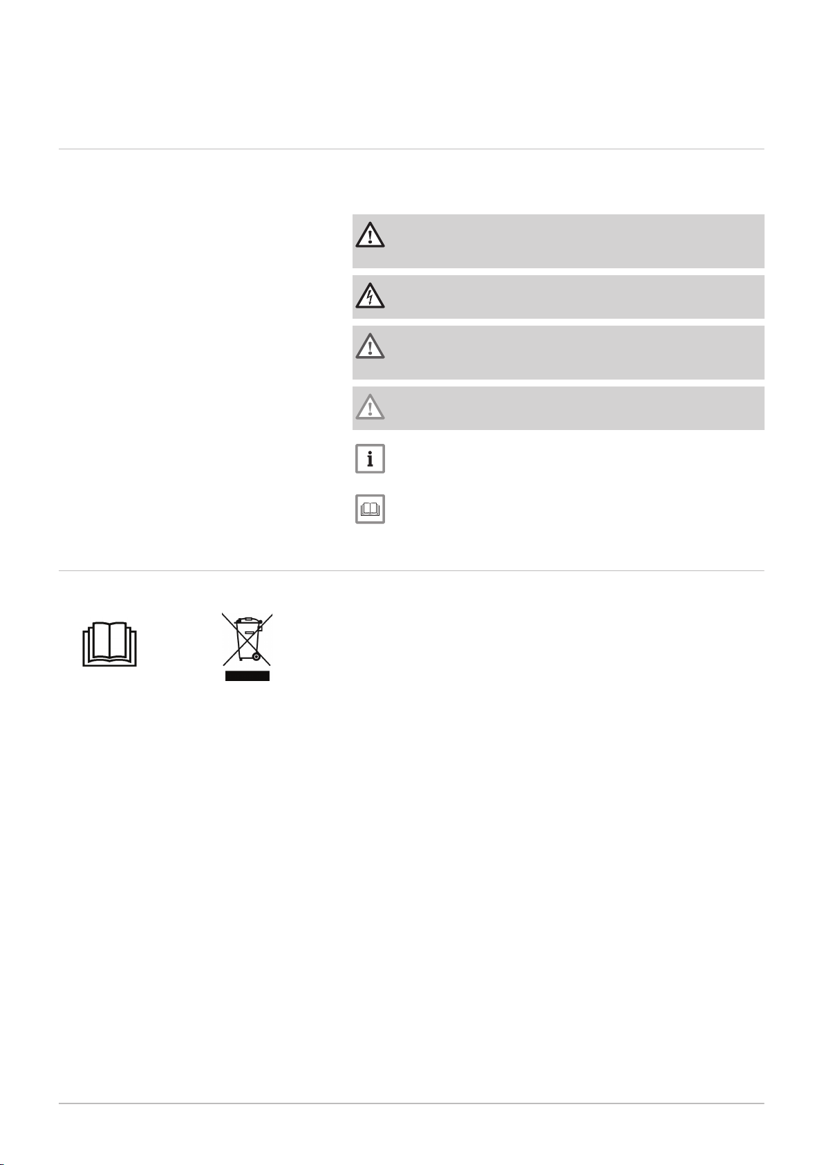
2.2 Symbols used on the equipment
Fig.1
Important
Please note: important information.
See
Reference to other manuals or pages in this manual.
1 Before installing and commissioning the appliance, carefully read
the instruction manuals provided
2 Dispose of used products in an appropriate recovery and recycling
structure
Page 8

3 Technical specifications
8 BPB 150...501 300027336 - v06 - 13062019
3 Technical specifications
3.1 Homologations
3.1.1 Certifications
This product complies with the requirements of the following European
Directives and Standards:
Low Voltage Directive 2014/35/EU
Generic standard: EN 60335-1
Relevant standards: EN 60335-2-40, EN 60335-2-21
Electromagnetic Compatibility Directive 2014/30/EU
Generic standards: EN 61000-6-3, EN 61000-6-1
Relevant Standard: EN 55014
3.1.2 2014/68/UE Directive
This product conforms to the requirements of European Directive
2014/68/UE, article 4, paragraph 3, on pressure equipment.
3.1.3 Ecodesign Directive
This product conforms to the requirements of European Directive
2009/125/EC on the ecodesign of energy-related products.
3.2 Technical data
3.2.1 Specifications of the domestic hot water tank
Tab.1
Unit BPB 150 BPB 200 BPB 300 BPB 401 BPB 501
Primary circuit: (Ex
changer)
Maximum operating tem
perature
Maximum operating
pressure
Exchanger capacity litres 5.6 8.1 11.4 14.8 20.8
Exchange surface
Water resistance at 3
3
/h
m
Secondary circuit (do
mestic water)
Maximum operating tem
perature
Maximum operating
pressure
Water capacity litres 145 195 290 385 485
Weight
Shipping weight (gross) kg 68 90 119 149,5 184,5
Weight of the domestic
hot water tank (net)
Performances related to
the boiler type
Output exchange
(1)
°C 110 110 110 110 110
MPa (bar) 1 (10) 1 (10) 1 (10) 1 (10) 1 (10)
2
m
kPa 12 14 17 20 26
°C 95 95 95 95 95
MPa (bar) 1 (10) 1 (10) 1 (10) 1 (10) 1 (10)
kg 51,5 78 106,5 137 172
kW 29 39 54 68 86
0.84 1.20 1.70 2.20 3.10
Page 9

3 Technical specifications
300027336 - v06 - 13062019 BPB 150...501 9
Unit BPB 150 BPB 200 BPB 300 BPB 401 BPB 501
Hourly flow rate (Domes
litres/h 710 960 1330 1670 2110
tic hot water, ∆T = 35
(1)
°C)
Draw-off capacity (∆T =
30°C) (10 minutes)
(2)
Standby heat loss
Litres/10
250 340 520 670 800
min
kWh/24 h 1,10 1.30 1,60 1,68 1,97
(ΔT=45K)
Performance N
(1)
Primary temperature: 80 °C - Domestic cold water inlet: 10 °C - Domestic hot water outlet: 45 °C - Primary flow rate: 3 m3/h
(2) Primary temperature: 80 °C - Domestic cold water inlet: 10 °C - Domestic hot water outlet: 40 °C - Domestic hot water tank: 60 °C
L
2.5 4.7 11 16 20
Technical data - Hot water storage tank
Tab.2 Technical parameters for hot water storage tank
Product name BPB 150 BPB 200 BPB 300 BPB 401 BPB 501
Storage volume V l 145 195 290 385 485
Standing loss S W 46 54 67 70 82
Page 10

4 Description of the product
10 BPB 150...501 300027336 - v06 - 13062019
4 Description of the product
4.1 General description
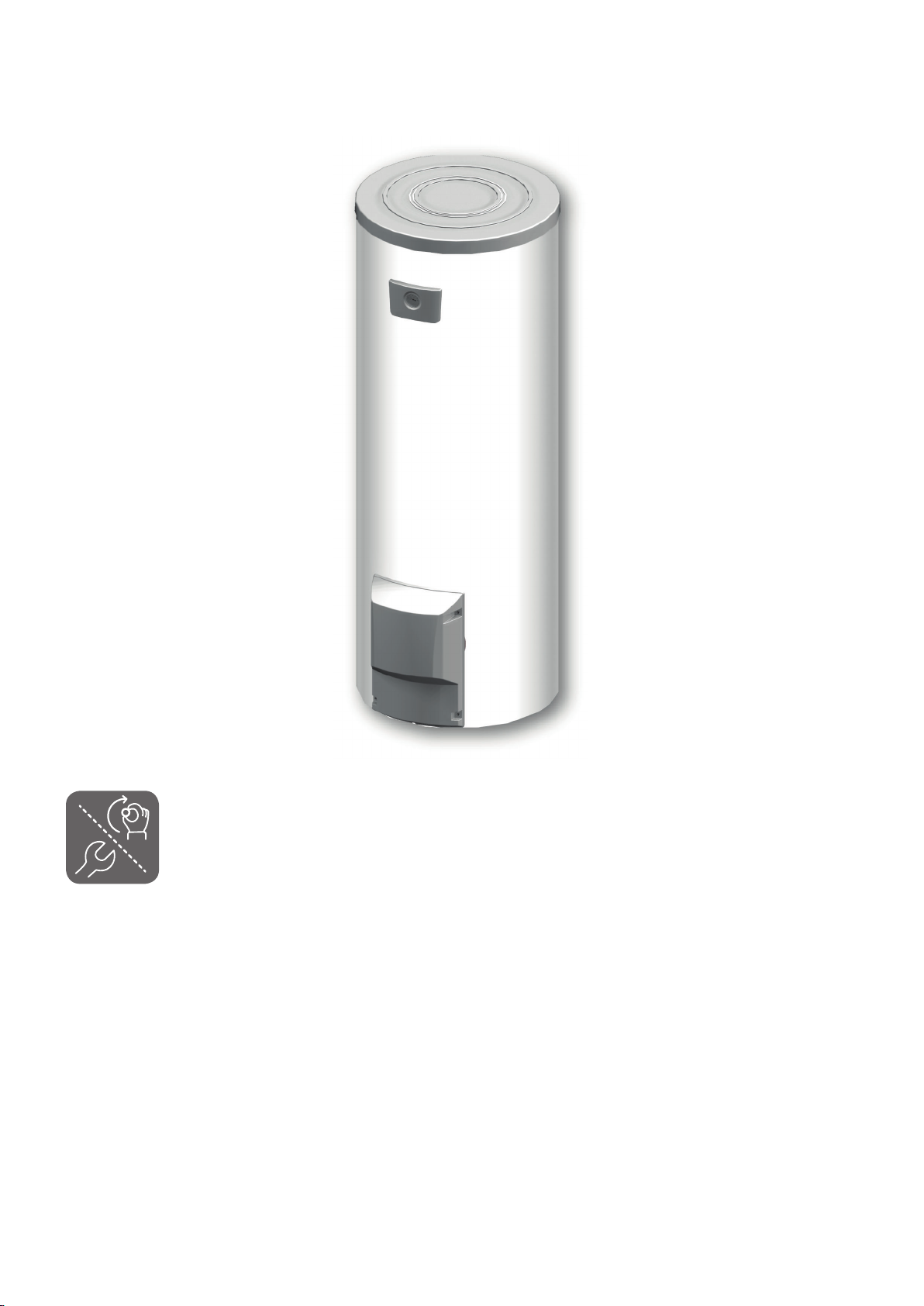
BPB 150...501 are high performance independent domestic hot water
tanks.
BPB 150...501 domestic hot water tanks can be connected to central
heating boilers used for heating domestic hot water.
Main components:
The tanks are made of high-quality steel lined with food-quality standard
enamel vitrified at 850 °C, which protects the tank from corrosion.
The heat exchanger welded into the tank is made of smooth tubing; its
external surface, which is in contact with domestic water, is enamelled.
The appliance is insulated with polyurethane foam, which helps to
reduce heat losses.
To facilitate material recycling, the insulation can be easily removed
from the vessel.
The external casing is made of ABS.
The tanks are protected against corrosion by one or more magnesium
anodes.
4.2 Standard delivery
The delivery includes:
One domestic hot water tank.
One installation, user and service manual.
Page 11

5 Before installation
MW-1001087-1
300027336 - v06 - 13062019 BPB 150...501 11
5.1 Installation regulations
5 Before installation
Important
Only qualified professionals are permitted to install the domestic
hot water tank, in accordance with prevailing local and national
regulations.
Danger
Limit temperature at draw-off points: the maximum domestic hot
water temperature at the draw-off points is the subject of special
regulations that vary from country to country in order to protect
consumers. These special regulations must be observed when
installing the appliance.
France:
Caution
The system must satisfy each point in the rules that govern works
and interventions in individual homes, blocks of flats or other
buildings.
5.2 Choice of the location
Fig.2
5.2.1 Data plate
The data plate affixed to the tank provides important information regarding
the appliance: serial number, model, etc. It must be accessible at all times.
5.2.2 Position of the appliance
Caution
Install the appliance in a frost-free location.
1. Position the appliance as close as possible to the draw-off points in
order to minimise energy losses through the pipes.
2. Place the appliance on a base frame to facilitate cleaning of the area.
3. Install the appliance on a solid, stable structure able to bear its weight.
Page 12

L000558-B
1
3
2
7
4
5
6
A
B
C
D
E
G
Ø F
5 Before installation
12 BPB 150...501 300027336 - v06 - 13062019
5.2.3 Main dimensions
Key to the diagrams
Tab.3
1 Domestic hot water outlet G1"
2 Circulation G¾"
3 Exchanger inlet G1"
4 Exchanger outlet G1"
5 Domestic cold water inlet and drain opening G1"
6 Anode
7 Sensor tube for DHW sensor
Important
G: Cylindrical threading, sealed by sheet gasket
Tab.4
BPB 150 BPB 200 BPB 300 BPB 401 BPB 501
A 70 70 70 66 71
B 282 282 282 282 283
C 612 747 972 972 1152
D 692 910 1262 1220 1348
E 844 1114 1634 1509 1618
F (Ø) 655 655 655 755 805
G 964 1234 1754 1642 1760
Fig.3
BPB 150
Page 13

Fig.4
L000559-B
G
Ø F
A
B
C
D
E
1
2
3
7
4
5
6
6
300027336 - v06 - 13062019 BPB 150...501 13
5 Before installation
BPB 200 – BPB 300 – BPB 401 – BPB 501
Page 14

200
350
200
200
MW-L000565-2
L000382-A
1
2
MW-C003702-2
1
3
2
6 Installation
14 BPB 150...501 300027336 - v06 - 13062019
6 Installation
6.1 Positioning the appliance
Fig.5
6.2
Fig.6
Caution
Have 2 people available.
Handle the appliance with gloves.
Caution
Leave 500 mm of clearance around the anodes to facilitate
access.
1. Remove the packaging from the tank but leave the tank on the
shipping pallet.
2. Remove the protective packaging.
3. Remove the three screws securing the tank to the pallet.
4. Lift the tank and place it in its final position, respecting the distances
shown on the diagram.
Levelling the domestic hot water tank
The domestic hot water tank is levelled using the three feet (supplied in
the bag) to be screwed to the bottom of the domestic hot water tank.
1. Screw the three adjustable feet to the bottom of the domestic hot
water tank.
2. Level the appliance using the adjustable feet.
Adjustment range: 10 mm.
Use metal blocks under the feet of the tank if necessary.
6.3
Fig.7
Caution
Do not place the blocks on the exterior sides of the domestic hot
water tank.
Putting the domestic hot water sensor in place
1. Position the probe in the sensor tube, using the sensor tube
separator.
Important
The sensor tube separator is provided in the documentation bag.
2. Check that the probes are correctly positioned in the sensor tube.
3. Check the mounting of the sensor tube separator.
Page 15

6.4 Hydraulic installation diagram
68
9
9
27
27
32
33
25
56
MW-L000369-C
24
30
50
50Hz
230V
46
16
64
67
B
A
11
21
27
9
1
4
2
3
300027336 - v06 - 13062019 BPB 150...501 15
Fig.8
6 Installation
6.4.1 Example with a wall-hung boiler or a heat pump
A Boiler, heat pump
B Regulator
1 Heating flow
2 Heating return
3 3-bar safety valve
4 Pressure gauge
7 Automatic air vent
9 Isolation valve
10 Three-way mixing valve
11 Heating pump
16 Expansion vessel
17 Drain valve
18 Filling the heating circuit
21 Outdoor temperature sensor
23 Flow temperature sensor after mixer valve
24 Domestic hot water tank exchanger primary inlet
25 Domestic hot water tank exchanger primary outlet
26 DHW booster pump
27 Non-return valve
28 Domestic cold water inlet
29 Pressure reducer
30 Safety unit
32 Domestic hot water circulation loop pump
33 Domestic hot water temperature sensor
44 Thermostat limiting the temperature to 65°C with
manual reset for underfloor heating
46 3-way directional valve with reversal motor
50 Disconnector
52 Differential valve
54 End of the discharge pipe free and visible 2 to 4 cm
above the flow funnel
56 Circulation
57 Domestic hot water outlet
64 Direct heating circuit (example: radiators)
65 Heating circuit which may be at low temperature
(heated floor or radiators)
67 Manual radiator valve
68 Condensates neutralisation system
109 Domestic hot water thermostatic mixing valve
201 DHW expansion vessel
Page 16

50
189
9
9
9
9
27
27
32
16
33
25
26
56
57
21
50Hz
230V
7
2
3
4
1
7
17
65
9
9
52
11
10
27
23
44
MW-L000368-C
4
24
30
9
A
L000370-C
(54)
2 cm
99
55
29
17
27
30
28
6 Installation
16 BPB 150...501 300027336 - v06 - 13062019
Fig.9
6.4.2 Example with a floor-standing boiler
A Boiler
1 Heating flow
2 Heating return
3 3-bar safety valve
4 Pressure gauge
7 Automatic air vent
9 Isolation valve
10 Three-way mixing valve
11 Heating pump
16 Expansion vessel
17 Drain valve
18 Filling the heating circuit
21 Outdoor temperature sensor
23 Flow temperature sensor after mixer valve
24 Domestic hot water tank exchanger primary inlet
25 Domestic hot water tank exchanger primary outlet
26 DHW booster pump
27 Non-return valve
28 Domestic cold water inlet
29 Pressure reducer
Fig.10
30 Safety unit
32 Domestic hot water circulation loop pump
33 Domestic hot water temperature sensor
44 Thermostat limiting the temperature to 65°C with
manual reset for underfloor heating
46 3-way directional valve with reversal motor
50 Disconnector
52 Differential valve
54 End of the discharge pipe free and visible 2 to 4 cm
above the flow funnel
56 Circulation
57 Domestic hot water outlet
64 Direct heating circuit (example: radiators)
65 Heating circuit which may be at low temperature
(heated floor or radiators)
67 Manual radiator valve
68 Condensates neutralisation system
109 Domestic hot water thermostatic mixing valve
201 DHW expansion vessel
6.4.3 Safety unit (except France)
9 Isolation valve
17 Drain valve
27 Non-return valve
28 Domestic cold water inlet
29 Pressure reducer
30 Safety unit
54 End of the discharge pipe free and visible 2 to 4 cm above the flow
funnel
55 Safety valve 0.7 MPa (7 bar)
Page 17

6.4.4 Safety unit (only for France)
MW-C000711-F
a
b
c
d
(54)
2 cm
e
289
30
29
300027336 - v06 - 13062019 BPB 150...501 17
6 Installation
Fig.11
6.5
9 Isolation valve
28 Domestic cold water inlet
29 Pressure reducer
30 Safety unit
54 End of the discharge pipe free and visible 2 to 4 cm above the flow
funnel
a Cold water inlet with an integrated non-return valve
b Connection at the cold water inlet of the DHW tank
c Stop cock
d Safety valve 0.7 MPa (7 bar)
e Drain opening
Hydraulic connections
6.5.1 Hydraulic connection of the primary circuit (exchanger circuit)
For the hydraulic connections of 200 L to 500 L tanks to the boiler (on the
left- or right-hand side), use the hydraulic connection kits provided as
optional extras.
For connection using these kits, refer to the instructions delivered with
them.
For more information, see
Hydraulic installation diagram, page 15
6.5.2
Connecting the tank to the domestic water circuit (secondary circuit)
During connection, it is imperative that the standards and corresponding
local directives be respected. Insulate the pipes to keep heat losses to a
minimum.
Belgium: Make the connections in accordance with Belgaqua technical
instructions.
Specific precautions
Before making the connection, flush the drinking water inlet pipes in order
not to allow metal or other particles into the appliance's tank.
Provision for Switzerland
Make the connections according to the requirements of the Société Suisse
de l'Industrie du Gaz et des Eaux Comply with local requirements from
water distribution plants.
Safety valve
Caution
In accordance with safety rules, a safety valve calibrated to 7 bar
(0.7 MPa) is mounted on the domestic hot water tank's domestic
cold water inlet.
France: We recommend NF-marked hydraulic diaphragm safety units.
Integrate the safety valve in the cold water circuit.
Install the safety valve close to the DHW tank in a place with easy
access.
Sizing
The diameter of the safety unit and its connection to the tank must be at
least equal to the diameter of the domestic cold water inlet on the tank.
Page 18

6 Installation
18 BPB 150...501 300027336 - v06 - 13062019
There must be no cut-off devices between the safety valve or unit and
the domestic hot water tank.
The discharge pipe in the safety valve or unit must not be blocked.
To avoid obstructing the flow of water in the event of overpressure:
Isolation valves
Hydraulically isolate the primary and domestic circuits with isolation valves
to facilitate maintenance on the domestic hot water tank. The valves make
it possible to carry out maintenance on the domestic hot water tank and its
components without draining the entire installation.
These valves are also used to isolate the domestic hot water tank when
conducting a pressurised check on the tightness of the installation if the
test pressure is greater than the admissible operating pressure for the
domestic hot water tank.
Connecting the domestic cold water
Connect to the cold water supply according to the hydraulic installation
diagram.
The components used for the connection to the cold water supply must
comply with the prevailing standards and regulations in the country
concerned.
Install a water drain in the boiler room and a funnel-siphon for the safety
unit.
Fit a non-return valve to the domestic cold water circuit.
Install a dielectric union on the domestic cold water inlet.
Pressure reducer
If the supply pressure exceeds 80% of the safety valve or unit calibration
(e.g.: 0.55 MPa/5.5 bar for a safety unit calibrated to 0.7 MPa/7 bar), a
pressure reducer must be located upstream of the appliance.
Install the pressure reducer downstream of the water meter in such a way
as to ensure the same pressure in all of the system's pipes.
Domestic hot water circulation loop
To guarantee the availability of hot water as soon as the taps are turned
on, a circulation loop between the draw-off points and the recirculation
pipes in the domestic hot water tank can be installed. A non-return valve
must be included in this loop.
Run the domestic hot water circulation loop via the boiler control system or
an additional timer program to optimise energy consumption.
Measures to take to prevent hot water flow return
Fit a non-return valve to the domestic cold water circuit.
Page 19

7 Commissioning
300027336 - v06 - 13062019 BPB 150...501 19
7.1 Protection against Legionella (500 litres only)
Warning
For domestic hot water tanks with a capacity of more than 400
litres: must comply with the Order titled "Protection against
legionella"
Apply one of the two settings below:
The domestic hot water at the appliance outlet must be at a temperature
of 55 °C or above at all times.
The domestic hot water must be brought up to a minimum temperature
for a minimum duration at least once every 24 hours. See table below:
Tab.5
Minimum temperature maintenance
time (minutes)
2 70 or above
4 65
60 60
7 Commissioning
France: Order of 30 November 2005
Germany: TrinkwV 2011 - Order of 01 November 2011 on water
quality
Other countries: Observe current regulations
Water temperature (°C)
7.2 Commissioning the appliance
Caution
Initial commissioning must be performed by a qualified
professional.
1. Flush the domestic water circuit and fill the tank through the cold
water inlet pipe.
2. Open a hot water tap.
3. Completely fill the domestic hot water tank via the cold water inlet
pipe, leaving the hot water tap open.
4. Close the hot water tap when the water flow is regular, without any
noises in the pipes.
5. Carefully vent all of the domestic hot water pipes by repeating steps 2
to 4 for each hot water tap.
Important
Carefully degas the domestic hot water tank and the distribution
network in order to eliminate noises and hammering caused by
trapped air moving in the pipes during draw-off.
6. Vent the DHW tank exchanger circuit using the air vent provided for
this purpose.
7. Check the safety components (particularly the safety valve or safety
unit), referring to the instructions provided with those components.
Caution
During the heating process, a certain amount of water may
escape via the safety valve or unit because of the expansion of
the water. This phenomenon is perfectly normal and no steps
should be taken to prevent it.
Page 20

7 Commissioning
20 BPB 150...501 300027336 - v06 - 13062019
7.3 Domestic water quality
In regions where the water is very hard (Th > 20 °fH (11 °dH)), we
recommend fitting a softener.
The water hardness must always be between 12 °fH (7 °dH) and 20 °fH
(11 °dH) to be capable of providing effective protection against corrosion.
The softener does not bring about a derogation from our warranty
provided that it is approved and set pursuant to the codes of practice and
the recommendations given in the instructions for the softener and is
regularly inspected and maintained.
Page 21

8 Maintenance
Ø > 15 mm =
Ø < 15 mm =
MW-C003699-4
7
300027336 - v06 - 13062019 BPB 150...501 21
8.1 General instructions
8.2 Safety valve or safety unit
8 Maintenance
Caution
Maintenance operations must be completed by a qualified
installer.
Use only genuine spare parts.
1. The safety valve or unit on the domestic cold water inlet must be
operated at least
properly and take precautions against possible pressure surges which
would damage the domestic hot water tank.
Warning
Failure to follow this maintenance requirement may lead to the
deterioration of the domestic hot water tank and void its warranty.
once a month in order to ensure that it works
8.3 Cleaning the casing
8.4 Checking the magnesium anode
Fig.12
8.5
Removing limescale
1. Clean the outside of appliances using a damp cloth and a mild
detergent.
The magnesium anode must be checked at least every 2 years After the
first check and in light of the degree of wear of the anode, it is necessary
to determine the frequency of future checks.
1. Remove the inspection hatches.
Important
Descale the DHW tank if necessary.
2. Measure the diameter of the anode.
Replace the anode if its diameter is less than 15 mm.
3. Reassemble the anode/inspection hatch unit.
For more information, see
Remove the inspection hatches, page 22
Putting the inspection hatches back in place, page 22
In hard water regions, we recommend annual descaling in order to
maintain performance.
1. Remove the inspection hatches.
2. Check the magnesium anode each time the hatch is opened.
3. Remove limescale deposits in the form of sludge or strips from the
bottom of the tank. However, do not touch the limescale adhering to
the walls of the tank as it provides effective protection against
corrosion and improves the insulation of the domestic hot water tank.
4. Remove limescale deposits from the exchanger to guarantee its
performance.
5. Remount the unit.
For more information, see
Remove the inspection hatches, page 22
Checking the magnesium anode, page 21
Putting the inspection hatches back in place, page 22
Page 22

MW-L000389-1
1
6x
8 Maintenance
22 BPB 150...501 300027336 - v06 - 13062019
8.6 Removing and reinstalling the inspection hatches.
Caution
Have a new lip gasket and a new retainer ring on hand for the
inspection hatch.
8.6.1 Remove the inspection hatches
1. Shut off the domestic cold water inlet.
2. Drain the tank.
Important
The domestic cold water inlet is also the drain opening.
3. Remove the inspection hatches.
8.6.2 Putting the inspection hatches back in place
Fig.13
Caution
To ensure tightness, the lip gasket and retainer ring unit must be
replaced by new parts each time the unit is opened.
1. Replace the lip gasket and position it in the inspection trap opening,
making sure that you place its lug outside the domestic hot water tank.
Page 23

A
2
B
2
MW-L000561-2
8 Maintenance
300027336 - v06 - 13062019 BPB 150...501 23
Fig.14
2. Replace the sheet gasket.
Tab.6
A Side inspection hatch without anode
B Side inspection hatch with anode
3. Remount the unit.
Caution
Use a torque wrench.
Magnesium anode: torque load 8 Nm.
The retaining screws on the inspection hatch must not be over
tightened.
Tab.7
Flange Torque load
Lip gasket 6 Nm +1/-0
Sheet gasket 15 Nm
Important
Approximately 6 Nm is obtained by manipulating the box spanner
with the small lever and 15 Nm by manipulating it with the large
lever.
4. After reassembly, check the tightness of the lateral flange.
5. Proceed with commissioning.
For more information, see
Commissioning the appliance, page 19
8.7 Maintenance form
Tab.8
No. Date Checks made Remarks By Signature
Page 24

8 Maintenance
24 BPB 150...501 300027336 - v06 - 13062019
No. Date Checks made Remarks By Signature
Page 25

9 Disposal and Recycling
MW-3000179-03
300027336 - v06 - 13062019 BPB 150...501 25
Fig.15
9 Disposal and Recycling
Important
Removal and disposal of the domestic hot water tank must be
carried out by a qualified installer in accordance with local and
national regulations.
1. Cut the electricity to the domestic hot water tank.
2. Disconnect the cables on the electrical components.
3. Close the domestic water inlet valve.
4. Drain the installation.
5. Dismantle all water connections fitted to the domestic hot water tank
outlet.
6. Scrap and recycle the domestic hot water tank in accordance with
local and national regulations.
Page 26

MW-L000604-3
1
11
4
7
3
8
9
17
6
5
18
16
4
5
6
15
4
5
6
14
10
11
4
6
5
2
13
12
2
10 Spare parts
26 BPB 150...501 300027336 - v06 - 13062019
10 Spare parts
10.1 General
When it is observed subsequent to inspection or maintenance work that a
component in the appliance needs to be replaced, use only original spare
parts or recommended spare parts and equipment.
Important
To order a spare part, give the reference number shown on the
list.
10.2
Fig.16
Domestic hot water tanks
Page 27

10 Spare parts
300027336 - v06 - 13062019 BPB 150...501 27
Tab.9
Mark
ers
Reference Description BPB
150
BPB
200
BPB
300
BPB
401
1 97860646 Adjustable foot M10 x 35 x x x x x
2 95365619 Sensor tube separator, 115cm x x x x x
3 200021501 Inspection hatch fittings x x x x x
4 95014035 Gasket Ø 35 x 8.5 x 2 x x x x x
5 94974527 Nylon spacer x x x x x
6 89604901 Anode earthing wire x x x x x
7 300026745 Insulation, top hatch x x x x x
8 7622105 Side cover x x x x x
9 7614394 Insulation side inspection trap x x x x x
10 89705511 Gasket 7 mm + retainer ring 5 mm x x x x x
11 300026031 Sheet gasket x x x x x
12 7688463 Side cover and thermometer x x x x x
13 7676809 AFRISO thermometer x x x x x
14 89555506 Complete top inspection hatch with one anode, gaskets
x
and screws
14 89555501 Complete top inspection hatch with one anode, gaskets
x
and screws
14 200022433 Complete top inspection hatch with one anode, gaskets
x
and screws
14 200007273 Complete top inspection hatch with one anode, gaskets
x
and screws
14 200022536 Complete top inspection hatch with one anode, gaskets
and screws
15 89608950 Complete anode, diameter 33 mm - length 420 mm (1x) -
x
for top inspection hatch
15 89588912 Complete anode, diameter 33 mm - length 290 mm (1x) -
x
for top inspection hatch
15 89708901 Complete anode, diameter 33 mm - length 330 mm (1x) -
x
for top inspection hatch
15 89628562 Complete anode, diameter 33 mm - length 450 mm (1x) -
x
for top inspection hatch
15 200022500 Complete anode, diameter 33 mm - length 530 mm (1x) -
for top inspection hatch
16 200021970 Complete side cover with gaskets and screws x
17 200022439 Complete side inspection hatch with anode, gaskets and
x
screws
17 200021971 Complete side inspection hatch with anode, gaskets and
x x
screws
17 200022441 Complete side inspection hatch with anode, gaskets and
screws
18 89538509 Complete anode, diameter 33 mm - length 180 mm (1x) -
x
for side inspection hatch
18 89708901 Complete anode, diameter 33 mm - length 330 mm (1x) -
x x
for side inspection hatch
18 89608950 Complete anode, diameter 33 mm - length 420 mm (1x) -
for side inspection hatch
BPB
501
x
x
x
x
Page 28

11 Warranty
28 BPB 150...501 300027336 - v06 - 13062019
11 Warranty
11.1 General
You have just purchased one of our appliances and we thank you for the
trust you have placed in our products.
Please note that your appliance will provide good service for a longer
period of time if it is regularly checked and maintained.
Our customer support network is at your disposal at all times.
11.2
Terms of warranty
France: The following provisions are not exclusive of the buyer being able
to benefit from the legal warranty stipulated in Articles 1641 to 1648 of the
Civil Code.
Belgium: The following provisions regarding the contractual warranty are
not exclusive of the buyer being able to benefit from the legal provisions
applicable in Belgium regarding hidden defects.
Switzerland: The warranty is applied in accordance with the terms of sale,
delivery and warranty of the company marketing De Dietrich products.
Portugal: The following provisions do not adversely affect consumers'
rights, as laid down in Decree-Law 67/2003 of 8 April amended by DecreeLaw 84/2008 of 21 May, warranties on sales of consumer goods and other
implementing rules.
Other countries: The following provisions do not affect the application, in
favour of the buyer, of the legal provisions with regard to hidden defects
that are applicable in the buyer's country.
The duration of our warranty is shown on the certificate delivered with the
appliance. As a manufacturer, we can by no means be held liable if the
appliance is used incorrectly, is poorly maintained or not maintained at all,
or is not installed correctly (it is your responsibility to ensure that
installation is carried out by a qualified professional).
The duration of our warranty is shown on the certificate delivered with the
appliance. As a manufacturer, we can by no means be held liable if the
appliance is used incorrectly, is poorly maintained or not maintained at all,
or is not installed correctly (it is your responsibility to ensure that
installation and maintenance works are carried out by a qualified
professional and by an after-sales service company, respectively).
The terms of warranty can be found on the warranty card. As a
manufacturer, we can by no means be held liable if the appliance is used
incorrectly, is poorly maintained or not maintained at all, or is not installed
correctly (it is your responsibility to ensure that installation is carried out by
a qualified professional).
The warranty period is stated in our price list. As a manufacturer, we can
by no means be held liable if the appliance is used incorrectly, is poorly
maintained or not maintained at all, or is not installed correctly (it is your
responsibility to ensure that installation is carried out by a qualified
installer).
In particular, we cannot be held liable for material damage, intangible
losses or physical injury resulting from an installation that does not comply
with:
the legal and regulatory requirements laid down by national laws and the
regulations of local authorities,
our instructions and prescriptions on installation and maintenance in
accordance with prevailing legislation.
Our warranty is limited to the replacement or repair of the parts found to
be defective by our technical services team, excluding labour, transfer and
transport costs.
Page 29

11 Warranty
300027336 - v06 - 13062019 BPB 150...501 29
Our warranty is limited to the replacement or repair of the parts found to
be defective by our technical services team.
The foregoing provisions in no way affect the rights of the consumer,
which are guaranteed by the legislation of the Russian Federation as
regards hidden defects. The terms and conditions of warranty and the
terms and conditions of application of the warranty are indicated on the
warranty form. The warranty shall not apply as regards the replacement or
repair of wearing parts under normal use. Such parts include
thermocouples, injection nozzles, flame control and ignition systems, fuses
and gaskets.
Page 30

BBBBB
12 Appendix
30 BPB 150...501 300027336 - v06 - 13062019
12 Appendix
12.1 Product fiche - Hot water storage tanks
Tab.10 Product fiche for hot water storage tanks
Brand name - Product name BPB 150 BPB 200 BPB 300 BPB 401 BPB 501
Energy efficiency class
Standing loss W 46 54 67 70 82
Storage volume l 145 195 290 385 485
Page 31

© Copyright
All technical and technological information contained in these technical instructions, as well as any drawings and technical
descriptions supplied, remain our property and shall not be multiplied without our prior consent in writing. Subject to alterations.
Page 32

DE DIETRICH
FRANCE
NEUBERG S.A.
LU
DE DIETRICH SERVICE
AT
DE DIETRICH
CN
www.dedietrich-thermique.fr
www.neuberg.lu
www.dedietrich-heating.com
www.dedietrich-heating.com
www.dedietrich-heiztechnik.com
SERVICE CONSOMMATEURS
0 825 120 520
0,15 €
/ min
03 88 80 27 00
03 88 80 27 99
+352 (0)2 401 401
0800 / 201608 freecall
+86 (0)106 581 4017
+86 (0)106 581 4018
+86 (0)106 581 7056
+86 (0)106 581 4019
contactBJ@dedietrich.com.cn
Direction de la Marque
57, rue de la Gare - F-67580 Mertzwiller
VAN MARCKE
BE
www.vanmarcke.be
+32 (0)56/23 75 11
Weggevoerdenlaan 5
B- 8500 KORTRIJK
39 rue Jacques Stas - B.P.12
L- 2549 LUXEMBOURG
Room 512, Tower A, Kelun Building
12A Guanghua Rd, Chaoyang District
C-100020 BEIJING
DE DIETRICH THERMIQUE
I
beria S.L.U
ES
www.dedietrich-calefaccion.es
+34 935 475 850
info@dedietrich-calefaccion.es
C/Salvador Espriu, 11
08908 L’HOSPITALET de LLOBREGAT
BDR THERMEA C
zech Republic s.r.o
CZ
DE DIETRICH
Technika Grzewcza sp. z o.o.
PL
www.dedietrich.cz
www.facebook.com/DeDietrichPL
www.dedietrich.pl
+420 271 001 627
dedietrich@bdrthermea.cz
+48 71 71 27 400
biuro@dedietrich.pl
MEIER TOBLER AG
CH
www.meiertobler.ch
+41 (0) 44 806 41 41
info@meiertobler.ch
Bahnstrasse 24 - CH - 8603 SCHWERZENBACH
Serviceline
+41 (0)8 00 846 846
MEIER TOBLER SA
CH
www.meiertobler.ch
+41 (0) 21 943 02 22
info@meiertobler.ch
Chemin de la Veyre-d'En-Haut B6,
CH -1806 St-Légier-La-Chiésaz
Jeseniova 2770/56 - 130 00 Praha 3
ul. Północna 15-19, 54-105 Wrocł aw
Serviceline
+41 (0)8 00 846 846
000 «БДP T Pyc»
RU
www.dedietrich.ru
8 800 333-17-18
info@dedietrich.ru
129164, Россия, г. Москва
Зубарев переулок, д. 15 /1
Бизнес-центр «Чайка Плаза»,офис 309
DUEDI S.r.
l
IT
www.duediclima.it
+39 0171 857170
+39 0171 687875
info@duediclima.it
Distributore Uffi ciale Esclusivo
De Dietrich-Thermique Italia Via Passatore, 12
12010 San Defendente di Cervasca CUNEO
801 080 881
Infocentrala
300027336 - v06 - 13062019
300027336-001-06
 Loading...