

Page 1
PROJECT
S U S T A I N A B L E C O M F O R T
®
EVODENS PRO
en
Istruzioni in ligua italiana disponibili su richiesta
Control panel & High-efficiency wall-hung gas boiler
Service Manual
AMC Pro 45 - 65 - 90 - 115
Diematic Evolution
Page 2

Contents
2 AMC Pro 7725087 - v.01 - 06062019
Contents
1 Safety . . . . . . . . . . . . . . . . . . . . . . . . . . . . . . . . . . . . . . . . . . . . . . . . . . . . . . . . . . . . . . . . . . . . . . . . . . . . . . . . . . . . . . . . . . . . 4
1.1 Liabilities . . . . . . . . . . . . . . . . . . . . . . . . . . . . . . . . . . . . . . . . . . . . . . . . . . . . . . . . . . . . . . . . . . . . . . . . . . . . . . . . . . . . . 4
1.1.1 Manufacturer's liability . . . . . . . . . . . . . . . . . . . . . . . . . . . . . . . . . . . . . . . . . . . . . . . . . . . . . . . . . . . . . . . . . . . 4
1.1.2 Installer's liability . . . . . . . . . . . . . . . . . . . . . . . . . . . . . . . . . . . . . . . . . . . . . . . . . . . . . . . . . . . . . . . . . . . . . . . 4
1.1.3 User's liability . . . . . . . . . . . . . . . . . . . . . . . . . . . . . . . . . . . . . . . . . . . . . . . . . . . . . . . . . . . . . . . . . . . . . . . . . .4
2 About this manual . . . . . . . . . . . . . . . . . . . . . . . . . . . . . . . . . . . . . . . . . . . . . . . . . . . . . . . . . . . . . . . . . . . . . . . . . . . . . . . . . . . 6
2.1 Additional documentation . . . . . . . . . . . . . . . . . . . . . . . . . . . . . . . . . . . . . . . . . . . . . . . . . . . . . . . . . . . . . . . . . . . . . . . . 6
2.2 Symbols used in the manual . . . . . . . . . . . . . . . . . . . . . . . . . . . . . . . . . . . . . . . . . . . . . . . . . . . . . . . . . . . . . . . . . . . . . .6
3 Description of the product . . . . . . . . . . . . . . . . . . . . . . . . . . . . . . . . . . . . . . . . . . . . . . . . . . . . . . . . . . . . . . . . . . . . . . . . . . . . . 7
3.1 General description . . . . . . . . . . . . . . . . . . . . . . . . . . . . . . . . . . . . . . . . . . . . . . . . . . . . . . . . . . . . . . . . . . . . . . . . . . . . .7
3.2 Main components . . . . . . . . . . . . . . . . . . . . . . . . . . . . . . . . . . . . . . . . . . . . . . . . . . . . . . . . . . . . . . . . . . . . . . . . . . . . . . 7
4 Use of the control panel . . . . . . . . . . . . . . . . . . . . . . . . . . . . . . . . . . . . . . . . . . . . . . . . . . . . . . . . . . . . . . . . . . . . . . . . . . . . . . 8
4.1 Control panel components . . . . . . . . . . . . . . . . . . . . . . . . . . . . . . . . . . . . . . . . . . . . . . . . . . . . . . . . . . . . . . . . . . . . . . . 8
4.2 Description of the home screen . . . . . . . . . . . . . . . . . . . . . . . . . . . . . . . . . . . . . . . . . . . . . . . . . . . . . . . . . . . . . . . . . . . 8
4.3 Description of the main menu . . . . . . . . . . . . . . . . . . . . . . . . . . . . . . . . . . . . . . . . . . . . . . . . . . . . . . . . . . . . . . . . . . . . . 8
5 User instructions . . . . . . . . . . . . . . . . . . . . . . . . . . . . . . . . . . . . . . . . . . . . . . . . . . . . . . . . . . . . . . . . . . . . . . . . . . . . . . . . . . . 10
5.1 Changing the display settings . . . . . . . . . . . . . . . . . . . . . . . . . . . . . . . . . . . . . . . . . . . . . . . . . . . . . . . . . . . . . . . . . . . . 10
5.2 Accessing the user level menus . . . . . . . . . . . . . . . . . . . . . . . . . . . . . . . . . . . . . . . . . . . . . . . . . . . . . . . . . . . . . . . . . . 10
5.3 Home screen . . . . . . . . . . . . . . . . . . . . . . . . . . . . . . . . . . . . . . . . . . . . . . . . . . . . . . . . . . . . . . . . . . . . . . . . . . . . . . . . .10
5.4 Activating holiday programs for all zones . . . . . . . . . . . . . . . . . . . . . . . . . . . . . . . . . . . . . . . . . . . . . . . . . . . . . . . . . . . 11
5.5 Heating circuit configuration . . . . . . . . . . . . . . . . . . . . . . . . . . . . . . . . . . . . . . . . . . . . . . . . . . . . . . . . . . . . . . . . . . . . . 11
5.6 Changing the room temperature of a zone . . . . . . . . . . . . . . . . . . . . . . . . . . . . . . . . . . . . . . . . . . . . . . . . . . . . . . . . . . 12
5.6.1 Definition of zone . . . . . . . . . . . . . . . . . . . . . . . . . . . . . . . . . . . . . . . . . . . . . . . . . . . . . . . . . . . . . . . . . . . . . .12
5.6.2 Changing the name and symbol of a zone . . . . . . . . . . . . . . . . . . . . . . . . . . . . . . . . . . . . . . . . . . . . . . . . . . 12
5.6.3 Changing the operating mode of a zone . . . . . . . . . . . . . . . . . . . . . . . . . . . . . . . . . . . . . . . . . . . . . . . . . . . . 13
5.6.4 Timer program to control the room temperature . . . . . . . . . . . . . . . . . . . . . . . . . . . . . . . . . . . . . . . . . . . . . . 13
5.6.5 Changing the heating activity temperatures . . . . . . . . . . . . . . . . . . . . . . . . . . . . . . . . . . . . . . . . . . . . . . . . . 15
5.6.6 Changing the room temperature temporarily . . . . . . . . . . . . . . . . . . . . . . . . . . . . . . . . . . . . . . . . . . . . . . . . . 15
5.7 Changing the domestic hot water temperature . . . . . . . . . . . . . . . . . . . . . . . . . . . . . . . . . . . . . . . . . . . . . . . . . . . . . . . 15
5.7.1 Changing the domestic hot water operating mode . . . . . . . . . . . . . . . . . . . . . . . . . . . . . . . . . . . . . . . . . . . . 15
5.7.2 Increasing the domestic hot water temperature temporarily . . . . . . . . . . . . . . . . . . . . . . . . . . . . . . . . . . . . . 15
5.7.3 Timer program to control the DHW temperature . . . . . . . . . . . . . . . . . . . . . . . . . . . . . . . . . . . . . . . . . . . . . . 16
5.7.4 Changing the comfort hot water temperature . . . . . . . . . . . . . . . . . . . . . . . . . . . . . . . . . . . . . . . . . . . . . . . . 16
5.8 Switching the central heating on or off . . . . . . . . . . . . . . . . . . . . . . . . . . . . . . . . . . . . . . . . . . . . . . . . . . . . . . . . . . . . . 17
5.9 Reading the installer's name and phone number . . . . . . . . . . . . . . . . . . . . . . . . . . . . . . . . . . . . . . . . . . . . . . . . . . . . . 17
6 Installer instructions . . . . . . . . . . . . . . . . . . . . . . . . . . . . . . . . . . . . . . . . . . . . . . . . . . . . . . . . . . . . . . . . . . . . . . . . . . . . . . . . .18
6.1 Accessing the installer level . . . . . . . . . . . . . . . . . . . . . . . . . . . . . . . . . . . . . . . . . . . . . . . . . . . . . . . . . . . . . . . . . . . . . 18
6.2 Configuring the installation at installer level . . . . . . . . . . . . . . . . . . . . . . . . . . . . . . . . . . . . . . . . . . . . . . . . . . . . . . . . . 18
6.2.1 Setting the installer details . . . . . . . . . . . . . . . . . . . . . . . . . . . . . . . . . . . . . . . . . . . . . . . . . . . . . . . . . . . . . . .19
6.2.2 Setting the parameters . . . . . . . . . . . . . . . . . . . . . . . . . . . . . . . . . . . . . . . . . . . . . . . . . . . . . . . . . . . . . . . . . 19
6.2.3 Changing boiler parameters when SCB-10 is fitted . . . . . . . . . . . . . . . . . . . . . . . . . . . . . . . . . . . . . . . . . . . .19
6.2.4 Setting the maximum load for CH operation . . . . . . . . . . . . . . . . . . . . . . . . . . . . . . . . . . . . . . . . . . . . . . . . . 20
6.2.5 Setting the heating curve . . . . . . . . . . . . . . . . . . . . . . . . . . . . . . . . . . . . . . . . . . . . . . . . . . . . . . . . . . . . . . . .21
6.2.6 Screed drying . . . . . . . . . . . . . . . . . . . . . . . . . . . . . . . . . . . . . . . . . . . . . . . . . . . . . . . . . . . . . . . . . . . . . . . . .21
6.3 Commissioning the installation . . . . . . . . . . . . . . . . . . . . . . . . . . . . . . . . . . . . . . . . . . . . . . . . . . . . . . . . . . . . . . . . . . . 22
6.3.1 Chimney sweep menu . . . . . . . . . . . . . . . . . . . . . . . . . . . . . . . . . . . . . . . . . . . . . . . . . . . . . . . . . . . . . . . . . . 22
6.3.2 Saving the commissioning settings . . . . . . . . . . . . . . . . . . . . . . . . . . . . . . . . . . . . . . . . . . . . . . . . . . . . . . . . 23
6.4 Maintaining the installation . . . . . . . . . . . . . . . . . . . . . . . . . . . . . . . . . . . . . . . . . . . . . . . . . . . . . . . . . . . . . . . . . . . . . . 24
6.4.1 Viewing the service notification . . . . . . . . . . . . . . . . . . . . . . . . . . . . . . . . . . . . . . . . . . . . . . . . . . . . . . . . . . . 24
6.4.2 Reading out measured values . . . . . . . . . . . . . . . . . . . . . . . . . . . . . . . . . . . . . . . . . . . . . . . . . . . . . . . . . . . .24
6.4.3 Viewing production and software information . . . . . . . . . . . . . . . . . . . . . . . . . . . . . . . . . . . . . . . . . . . . . . . . 24
6.4.4 Changing the domestic hot water temperature temporarily . . . . . . . . . . . . . . . . . . . . . . . . . . . . . . . . . . . . . . 25
6.5 Resetting or restoring settings . . . . . . . . . . . . . . . . . . . . . . . . . . . . . . . . . . . . . . . . . . . . . . . . . . . . . . . . . . . . . . . . . . . 25
6.5.1 Resetting the configuration numbers CN1 and CN2 . . . . . . . . . . . . . . . . . . . . . . . . . . . . . . . . . . . . . . . . . . . 25
6.5.2 Carrying out an auto-detect for the CAN matrix . . . . . . . . . . . . . . . . . . . . . . . . . . . . . . . . . . . . . . . . . . . . . . .25
6.5.3 Restoring the commissioning settings . . . . . . . . . . . . . . . . . . . . . . . . . . . . . . . . . . . . . . . . . . . . . . . . . . . . . . 25
6.5.4 Resetting to factory settings . . . . . . . . . . . . . . . . . . . . . . . . . . . . . . . . . . . . . . . . . . . . . . . . . . . . . . . . . . . . . 26
7 Installation examples . . . . . . . . . . . . . . . . . . . . . . . . . . . . . . . . . . . . . . . . . . . . . . . . . . . . . . . . . . . . . . . . . . . . . . . . . . . . . . . .27
Page 3

Contents
7725087 - v.01 - 06062019 AMC Pro 3
7.1 Access to the expansion box . . . . . . . . . . . . . . . . . . . . . . . . . . . . . . . . . . . . . . . . . . . . . . . . . . . . . . . . . . . . . . . . . . . . 27
7.2 Connection options for the expansion PCB - SCB-10 . . . . . . . . . . . . . . . . . . . . . . . . . . . . . . . . . . . . . . . . . . . . . . . . . 27
7.3 Zone functions of SCB-10 . . . . . . . . . . . . . . . . . . . . . . . . . . . . . . . . . . . . . . . . . . . . . . . . . . . . . . . . . . . . . . . . . . . . . . .28
7.4 Setting the 0-10 Volt input function of SCB-10 . . . . . . . . . . . . . . . . . . . . . . . . . . . . . . . . . . . . . . . . . . . . . . . . . . . . . . . 29
7.4.1 Analogue temperature regulation (°C) . . . . . . . . . . . . . . . . . . . . . . . . . . . . . . . . . . . . . . . . . . . . . . . . . . . . . .30
7.4.2 Analogue output-based control . . . . . . . . . . . . . . . . . . . . . . . . . . . . . . . . . . . . . . . . . . . . . . . . . . . . . . . . . . . 30
7.5 Cascade control . . . . . . . . . . . . . . . . . . . . . . . . . . . . . . . . . . . . . . . . . . . . . . . . . . . . . . . . . . . . . . . . . . . . . . . . . . . . . . 30
7.6 Connecting diagrams . . . . . . . . . . . . . . . . . . . . . . . . . . . . . . . . . . . . . . . . . . . . . . . . . . . . . . . . . . . . . . . . . . . . . . . . . . 31
7.6.1 Symbols used . . . . . . . . . . . . . . . . . . . . . . . . . . . . . . . . . . . . . . . . . . . . . . . . . . . . . . . . . . . . . . . . . . . . . . . . 31
7.6.2 Connection example 1 . . . . . . . . . . . . . . . . . . . . . . . . . . . . . . . . . . . . . . . . . . . . . . . . . . . . . . . . . . . . . . . . . .33
7.6.3 Connection example 2 . . . . . . . . . . . . . . . . . . . . . . . . . . . . . . . . . . . . . . . . . . . . . . . . . . . . . . . . . . . . . . . . . .34
7.6.4 Connection example 3 . . . . . . . . . . . . . . . . . . . . . . . . . . . . . . . . . . . . . . . . . . . . . . . . . . . . . . . . . . . . . . . . . .35
7.6.5 Connection example 4 . . . . . . . . . . . . . . . . . . . . . . . . . . . . . . . . . . . . . . . . . . . . . . . . . . . . . . . . . . . . . . . . . .36
7.6.6 Connection example 5 . . . . . . . . . . . . . . . . . . . . . . . . . . . . . . . . . . . . . . . . . . . . . . . . . . . . . . . . . . . . . . . . . .38
7.6.7 Connection example 6 . . . . . . . . . . . . . . . . . . . . . . . . . . . . . . . . . . . . . . . . . . . . . . . . . . . . . . . . . . . . . . . . . .40
7.6.8 Connection example 10 . . . . . . . . . . . . . . . . . . . . . . . . . . . . . . . . . . . . . . . . . . . . . . . . . . . . . . . . . . . . . . . . .43
7.6.9 Connection example 11 . . . . . . . . . . . . . . . . . . . . . . . . . . . . . . . . . . . . . . . . . . . . . . . . . . . . . . . . . . . . . . . . .45
7.6.10 Connection example 12 . . . . . . . . . . . . . . . . . . . . . . . . . . . . . . . . . . . . . . . . . . . . . . . . . . . . . . . . . . . . . . . . . 48
7.6.11 Connection example 14 . . . . . . . . . . . . . . . . . . . . . . . . . . . . . . . . . . . . . . . . . . . . . . . . . . . . . . . . . . . . . . . . . 50
7.6.12 Connection example 16 . . . . . . . . . . . . . . . . . . . . . . . . . . . . . . . . . . . . . . . . . . . . . . . . . . . . . . . . . . . . . . . . . 52
7.6.13 Connection example 18 . . . . . . . . . . . . . . . . . . . . . . . . . . . . . . . . . . . . . . . . . . . . . . . . . . . . . . . . . . . . . . . . . 55
8 Settings . . . . . . . . . . . . . . . . . . . . . . . . . . . . . . . . . . . . . . . . . . . . . . . . . . . . . . . . . . . . . . . . . . . . . . . . . . . . . . . . . . . . . . . . . . 56
8.1 Introduction to parameter codes . . . . . . . . . . . . . . . . . . . . . . . . . . . . . . . . . . . . . . . . . . . . . . . . . . . . . . . . . . . . . . . . . . 56
8.2 List of parameters . . . . . . . . . . . . . . . . . . . . . . . . . . . . . . . . . . . . . . . . . . . . . . . . . . . . . . . . . . . . . . . . . . . . . . . . . . . . . 56
8.2.1 Control unit settings . . . . . . . . . . . . . . . . . . . . . . . . . . . . . . . . . . . . . . . . . . . . . . . . . . . . . . . . . . . . . . . . . . . .56
8.2.2 SCB-10 expansion PCB settings . . . . . . . . . . . . . . . . . . . . . . . . . . . . . . . . . . . . . . . . . . . . . . . . . . . . . . . . . .62
8.3 List of measured values . . . . . . . . . . . . . . . . . . . . . . . . . . . . . . . . . . . . . . . . . . . . . . . . . . . . . . . . . . . . . . . . . . . . . . . . 77
8.3.1 Control unit counters . . . . . . . . . . . . . . . . . . . . . . . . . . . . . . . . . . . . . . . . . . . . . . . . . . . . . . . . . . . . . . . . . . . 77
8.3.2 SCB-10 expansion PCB counters . . . . . . . . . . . . . . . . . . . . . . . . . . . . . . . . . . . . . . . . . . . . . . . . . . . . . . . . . 78
8.3.3 Control unit signals . . . . . . . . . . . . . . . . . . . . . . . . . . . . . . . . . . . . . . . . . . . . . . . . . . . . . . . . . . . . . . . . . . . . 79
8.3.4 SCB-10 expansion PCB signals . . . . . . . . . . . . . . . . . . . . . . . . . . . . . . . . . . . . . . . . . . . . . . . . . . . . . . . . . . 81
9 Maintenance . . . . . . . . . . . . . . . . . . . . . . . . . . . . . . . . . . . . . . . . . . . . . . . . . . . . . . . . . . . . . . . . . . . . . . . . . . . . . . . . . . . . . . 87
9.1 Maintenance regulations . . . . . . . . . . . . . . . . . . . . . . . . . . . . . . . . . . . . . . . . . . . . . . . . . . . . . . . . . . . . . . . . . . . . . . . .87
9.2 Opening the boiler . . . . . . . . . . . . . . . . . . . . . . . . . . . . . . . . . . . . . . . . . . . . . . . . . . . . . . . . . . . . . . . . . . . . . . . . . . . . .87
9.3 Standard inspection and maintenance operations . . . . . . . . . . . . . . . . . . . . . . . . . . . . . . . . . . . . . . . . . . . . . . . . . . . . 87
9.3.1 Checking the water pressure . . . . . . . . . . . . . . . . . . . . . . . . . . . . . . . . . . . . . . . . . . . . . . . . . . . . . . . . . . . . .87
9.3.2 Checking the ionisation current . . . . . . . . . . . . . . . . . . . . . . . . . . . . . . . . . . . . . . . . . . . . . . . . . . . . . . . . . . . 88
9.3.3 Checking the flue gas outlet/air supply connections . . . . . . . . . . . . . . . . . . . . . . . . . . . . . . . . . . . . . . . . . . . 88
9.3.4 Checking the combustion . . . . . . . . . . . . . . . . . . . . . . . . . . . . . . . . . . . . . . . . . . . . . . . . . . . . . . . . . . . . . . . 88
9.3.5 Cleaning the siphon . . . . . . . . . . . . . . . . . . . . . . . . . . . . . . . . . . . . . . . . . . . . . . . . . . . . . . . . . . . . . . . . . . . .91
9.3.6 Checking the burner and cleaning the heat exchanger . . . . . . . . . . . . . . . . . . . . . . . . . . . . . . . . . . . . . . . . . 92
9.3.7 Checking the non-return valve . . . . . . . . . . . . . . . . . . . . . . . . . . . . . . . . . . . . . . . . . . . . . . . . . . . . . . . . . . . .93
9.4 Specific maintenance work . . . . . . . . . . . . . . . . . . . . . . . . . . . . . . . . . . . . . . . . . . . . . . . . . . . . . . . . . . . . . . . . . . . . . . 94
9.4.1 Replacing the ionisation/ignition electrode . . . . . . . . . . . . . . . . . . . . . . . . . . . . . . . . . . . . . . . . . . . . . . . . . . 94
9.4.2 Cleaning the condensate collector . . . . . . . . . . . . . . . . . . . . . . . . . . . . . . . . . . . . . . . . . . . . . . . . . . . . . . . . .95
9.5 Finalising work . . . . . . . . . . . . . . . . . . . . . . . . . . . . . . . . . . . . . . . . . . . . . . . . . . . . . . . . . . . . . . . . . . . . . . . . . . . . . . . 97
10 Troubleshooting . . . . . . . . . . . . . . . . . . . . . . . . . . . . . . . . . . . . . . . . . . . . . . . . . . . . . . . . . . . . . . . . . . . . . . . . . . . . . . . . . . . .98
10.1 Error codes . . . . . . . . . . . . . . . . . . . . . . . . . . . . . . . . . . . . . . . . . . . . . . . . . . . . . . . . . . . . . . . . . . . . . . . . . . . . . . . . . . 98
10.1.1 Display of error codes . . . . . . . . . . . . . . . . . . . . . . . . . . . . . . . . . . . . . . . . . . . . . . . . . . . . . . . . . . . . . . . . . . 98
10.1.2 Warning . . . . . . . . . . . . . . . . . . . . . . . . . . . . . . . . . . . . . . . . . . . . . . . . . . . . . . . . . . . . . . . . . . . . . . . . . . . . . 98
10.1.3 Blocking . . . . . . . . . . . . . . . . . . . . . . . . . . . . . . . . . . . . . . . . . . . . . . . . . . . . . . . . . . . . . . . . . . . . . . . . . . . . 101
10.1.4 Locking . . . . . . . . . . . . . . . . . . . . . . . . . . . . . . . . . . . . . . . . . . . . . . . . . . . . . . . . . . . . . . . . . . . . . . . . . . . . 108
10.2 Error history . . . . . . . . . . . . . . . . . . . . . . . . . . . . . . . . . . . . . . . . . . . . . . . . . . . . . . . . . . . . . . . . . . . . . . . . . . . . . . . . .111
10.2.1 Reading out and clearing the error memory . . . . . . . . . . . . . . . . . . . . . . . . . . . . . . . . . . . . . . . . . . . . . . . . 111
11 Technical specifications . . . . . . . . . . . . . . . . . . . . . . . . . . . . . . . . . . . . . . . . . . . . . . . . . . . . . . . . . . . . . . . . . . . . . . . . . . . . 112
11.1 Electrical diagram . . . . . . . . . . . . . . . . . . . . . . . . . . . . . . . . . . . . . . . . . . . . . . . . . . . . . . . . . . . . . . . . . . . . . . . . . . . . 112
12 Spare parts . . . . . . . . . . . . . . . . . . . . . . . . . . . . . . . . . . . . . . . . . . . . . . . . . . . . . . . . . . . . . . . . . . . . . . . . . . . . . . . . . . . . . . 114
12.1 General . . . . . . . . . . . . . . . . . . . . . . . . . . . . . . . . . . . . . . . . . . . . . . . . . . . . . . . . . . . . . . . . . . . . . . . . . . . . . . . . . . . . 114
12.2 Parts . . . . . . . . . . . . . . . . . . . . . . . . . . . . . . . . . . . . . . . . . . . . . . . . . . . . . . . . . . . . . . . . . . . . . . . . . . . . . . . . . . . . . . 115
12.3 Spare part list . . . . . . . . . . . . . . . . . . . . . . . . . . . . . . . . . . . . . . . . . . . . . . . . . . . . . . . . . . . . . . . . . . . . . . . . . . . . . . . 119
Page 4

1 Safety
4 AMC Pro 7725087 - v.01 - 06062019
1 Safety
1.1 Liabilities
1.1.1 Manufacturer's liability
Our products are manufactured in compliance with the
requirements of the various Directives applicable. They
are therefore delivered with the marking and any
documents necessary. In the interests of the quality of
our products, we strive constantly to improve them. We
therefore reserve the right to modify the specifications
given in this document.
Our liability as manufacturer may not be invoked in the
following cases:
Failure to abide by the instructions on installing and
maintaining the appliance.
Failure to abide by the instructions on using the
appliance.
Faulty or insufficient maintenance of the appliance.
1.1.2
The installer is responsible for the installation and initial
commissioning of the appliance. The installer must
observe the following instructions:
Read and follow the instructions given in the manuals
provided with the appliance.
Install the appliance in compliance with prevailing
legislation and standards.
Carry out initial commissioning and any checks
necessary.
Explain the installation to the user.
If maintenance is necessary, warn the user of the
obligation to check the appliance and keep it in good
working order.
Give all the instruction manuals to the user.
Installer's liability
1.1.3 User's liability
To guarantee optimum operation of the system, you
must abide by the following instructions:
Read and follow the instructions given in the manuals
provided with the appliance.
Call on a qualified professional to carry out installation
and initial commissioning.
Get your installer to explain your installation to you.
Page 5

1 Safety
7725087 - v.01 - 06062019 AMC Pro 5
Have the required inspections and maintenance
carried out by a qualified installer.
Keep the instruction manuals in good condition close
to the appliance.
Page 6
2 About this manual
6 AMC Pro 7725087 - v.01 - 06062019
2 About this manual
2.1 Additional documentation
The following documentation is available in addition to this manual:
Installation and user manual
Water quality instructions
2.2
Symbols used in the manual
This manual contains special instructions, marked with specific symbols.
Please pay extra attention when these symbols are used.
Caution
Risk of material damage.
Important
Please note: important information.
See
Reference to other manuals or pages in this manual.
Page 7
AD-4000070-01
17
14
13
10
9
6
7
8
2
1
12
3
4
11
5
18
19
20
16
15
3 Description of the product
7725087 - v.01 - 06062019 AMC Pro 7
3 Description of the product
The AMC Pro boiler is delivered with a combination of the control panel,
control unit and extension PCB. The contents of this manual are based on
the following software and navigation information:
Tab.1 Software and navigation information
Name visible in display Software version
Boiler AMC Pro CU-GH08 1.7
Control panel Diematic Evolution MK3 1.29
PCB SCB-10 SCB-10 1.03
3.1
General description
3.2 Main components
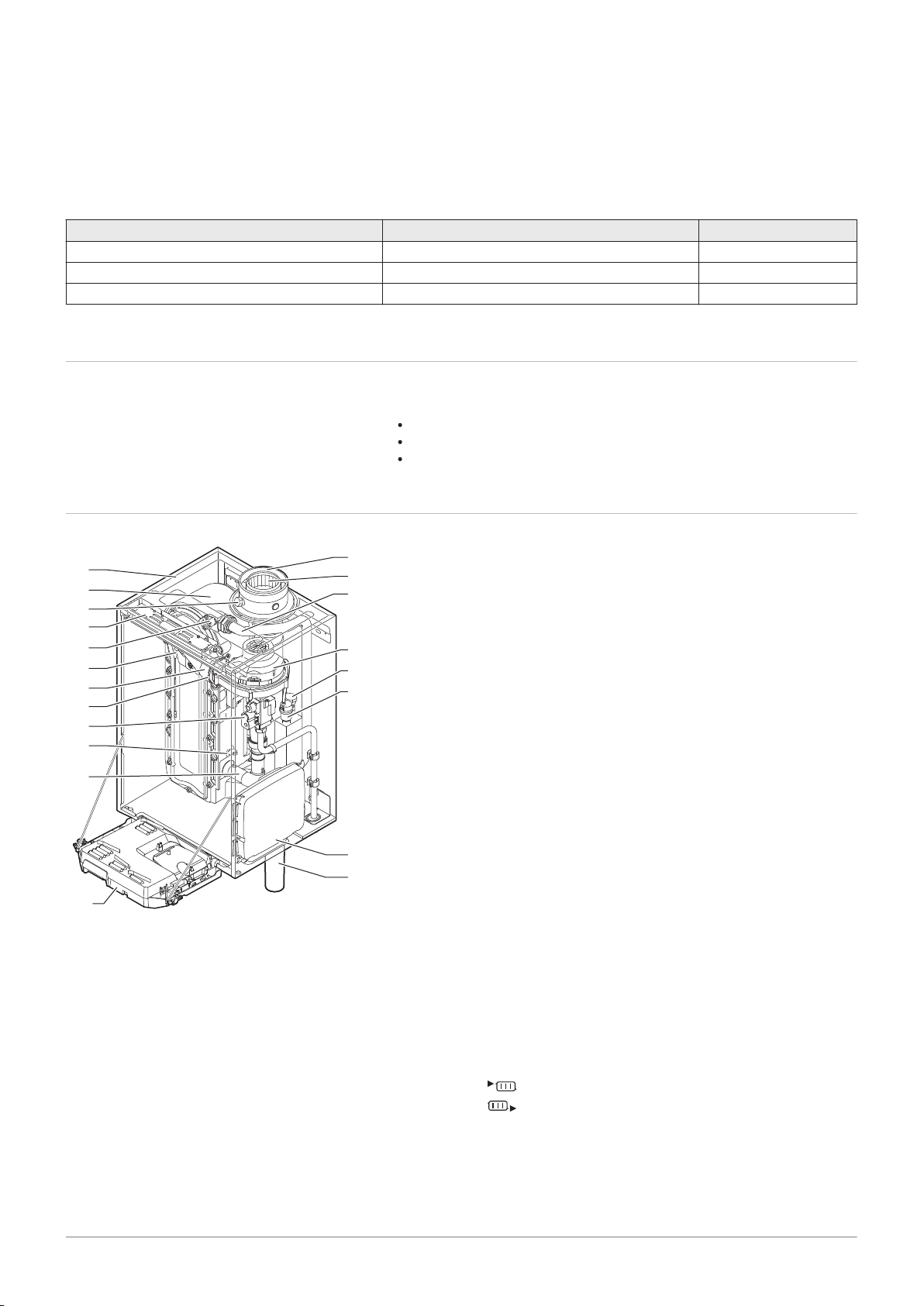
Fig.1
Main components
The AMC Pro boiler is a high-efficiency wall-hung gas boiler with the
following properties:
High-efficiency heating.
Limited emissions of polluting substances.
Ideal choice for cascade configurations.
1
Casing/air box
2
Heat exchanger (CH)
3
Interior light
4
Type plate
5
Flow sensor
6
Ionisation/ignition electrode
7
Mixing tube
8
Non-return valve
9
Combined gas valve unit
10
Return sensor
11
Air intake silencer
12
Instrument box
13
Siphon
14
Expansion box for the control PCBs
15
Automatic air vent
16
Hydraulic pressure sensor
17
Fan
18
Supply line
19
Flue gas measuring point
20
Flue gas discharge pipe
21
Air supply
Heating circuit flow
Heating circuit return
Page 8
AD-3000932-01
3
4
1
6
2
5
AD-3001157-01
All OK
Error Status
22/02/2018 11:20 Home Screen
i
i
All OK
2
5
43
1
AD-3000935-01
A B
C
4 Use of the control panel
8 AMC Pro 7725087 - v.01 - 06062019
4 Use of the control panel
4.1 Control panel components
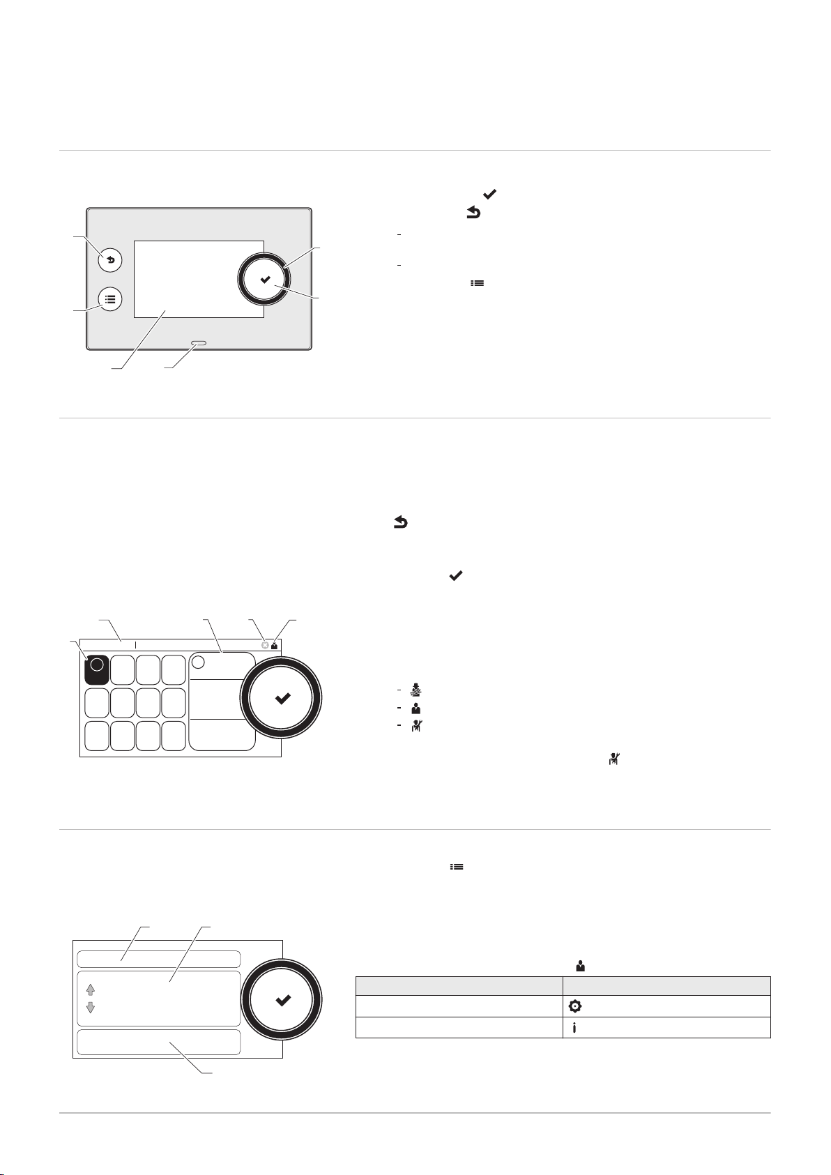
Fig.2 Control panel components
4.2
Description of the home screen
1 Rotary knob to select a tile, menu or setting
2
Confirm button to confirm the selection
3
Back button :
Short button press: Return to the previous level or previous
menu
Long button press: Return to home screen
4
Menu button to go to the main menu
5 Display
6 Status LED
This screen is shown automatically after start-up of the appliance. The
control panel goes automatically in standby mode (black screen) if the
screen is not touched for 5 minutes. Press one of the buttons on the
control panel to activate the screen again.
You can navigate from any menu to the home screen by pressing the back
button
for several seconds.
The tiles on the home screen provide quick access to the corresponding
menus. Use the rotary knob to navigate to the menu of your choice and
press the button to confirm the selection.
Fig.3 Icons on home screen
4.3
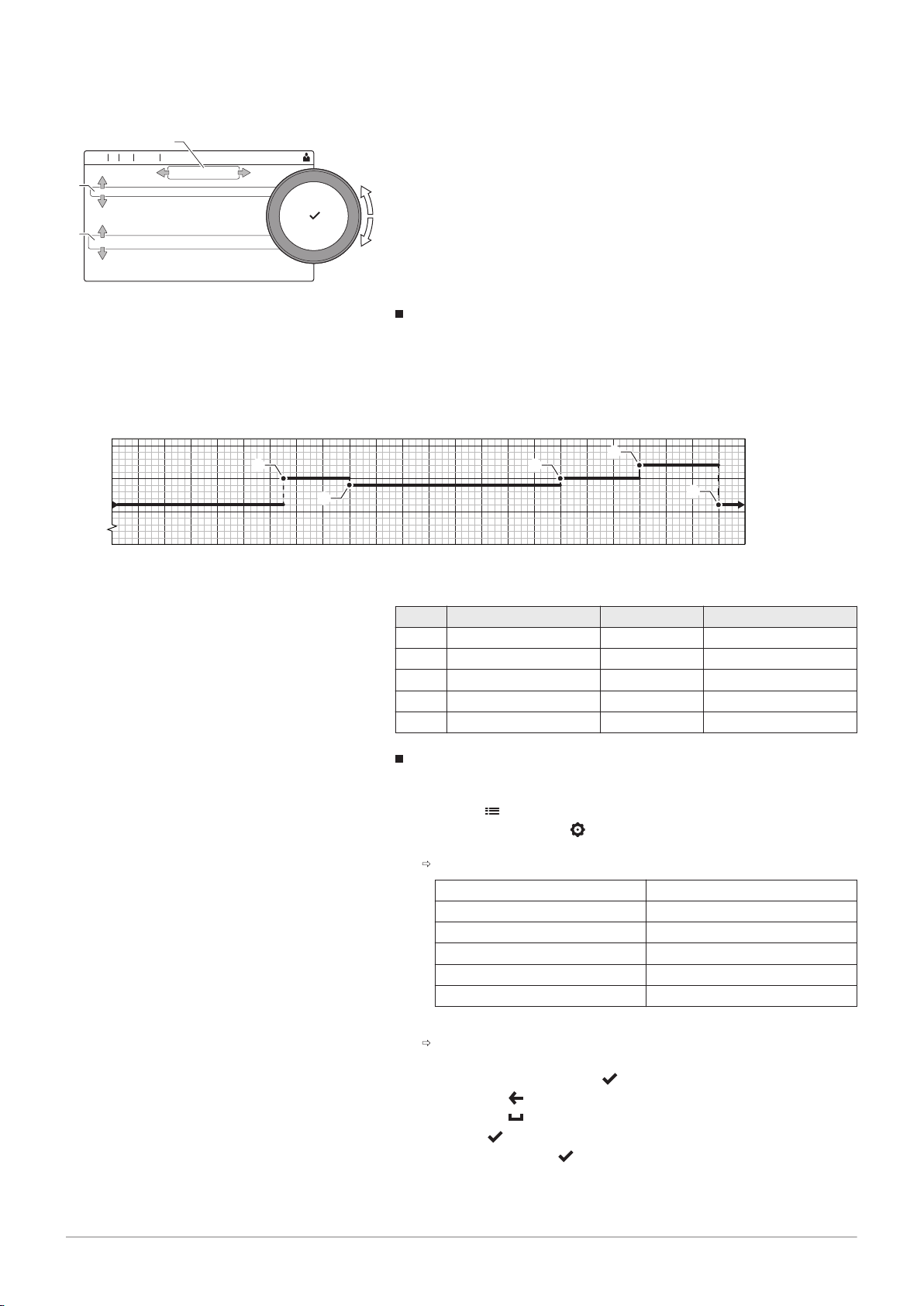
Fig.4 Items in the main menu
Description of the main menu
1 Tiles: the selected tile is highlighted
2 Date and time | Name of the screen (actual position in the menu)
3 Information about the selected tile
4 Error indicator (only visible if an error has been found)
5 Icon showing the navigation level:
: Chimney sweeper level
: User level
: Installer level
The installer level is protected by an access code. When this
level is active, the status of the tile [
] changes from Off into
On.
You can navigate from any menu directly to the main menu by pressing
the menu button
. The number of accessible menus depends on the
access level (user or installer).
A
Date and time | Name of the screen (actual position in the menu)
B
Available menus
C
Brief explanation of the selected menu
Tab.2
Available menus for the user
Description Icon
System Settings
Version Information
Page 9

4 Use of the control panel
7725087 - v.01 - 06062019 AMC Pro 9
Tab.3
Available menus for the installer
Description Icon
Installation Setup
Commissioning Menu
Advanced Service Menu
Error History
System Settings
Version Information
Page 10
AD-3001387-01
Not set
Home Screen
22/02/2018 11:20
... ...
........ .......
........ .......
......
AD-3001388-01
... ...
........ .......
........ .......
......
Not set
Home Screen
22/02/2018 11:20
5 User instructions
10 AMC Pro 7725087 - v.01 - 06062019
5 User instructions
5.1 Changing the display settings
1. Press the button.
2. Select System Settings .
3. Perform one of the operations described in the table below:
Tab.4 Display settings
System Settings menu Settings
Set Date and Time Set the currrent date and time
Select Country and Language Select your country and language
Daylight Saving Time Enable or disable daylight saving time
Installer Details Read out the name and phone number of the installer
Set Heating Activity Names Create the names for the activities of the timer program
Set Screen Brightness Adjust the brightness of the screen
Set click sound Enable or disable the click sound of the rotary knob
License Information Read out detailed license information from the device platform application
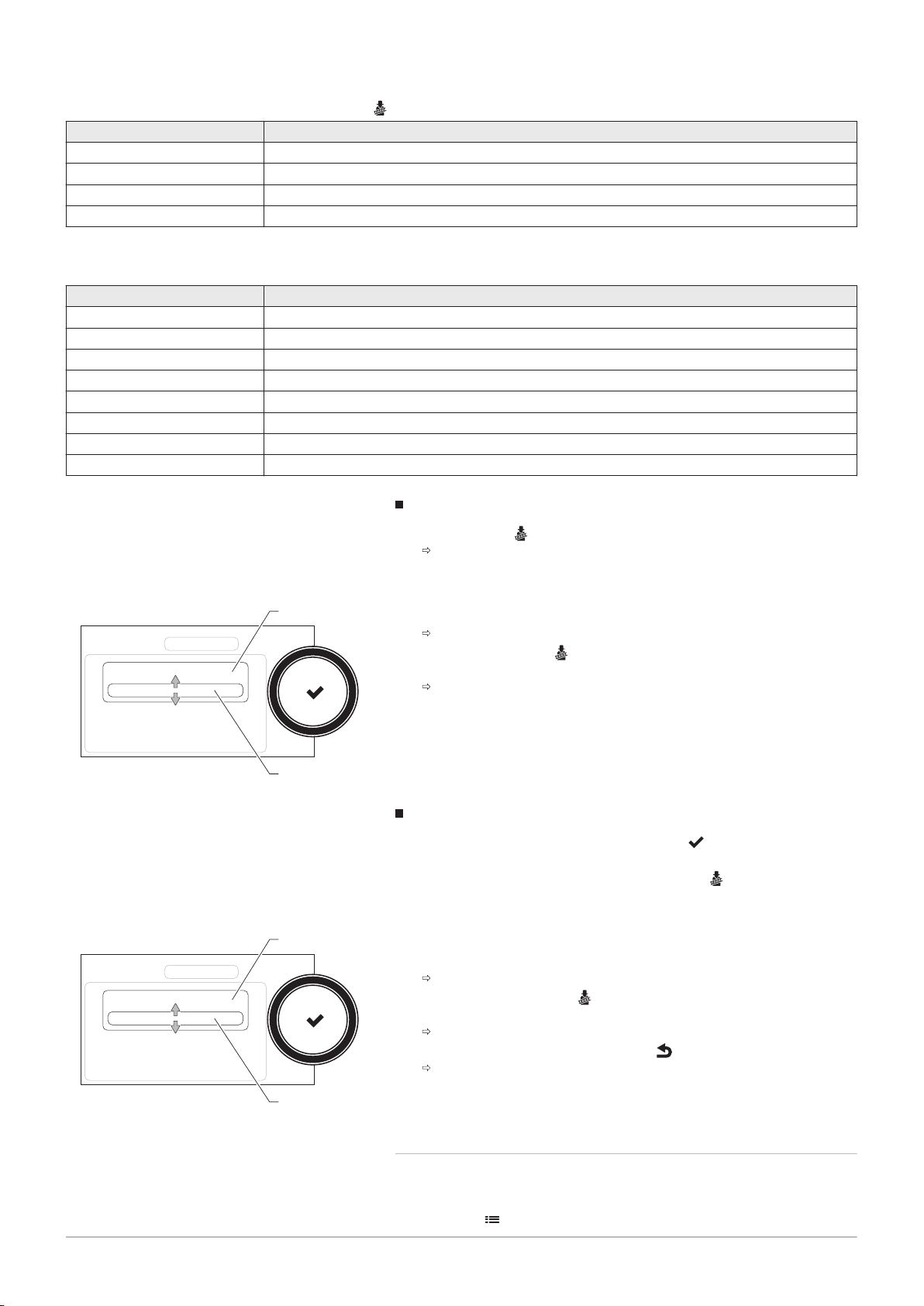
5.2 Accessing the user level menus
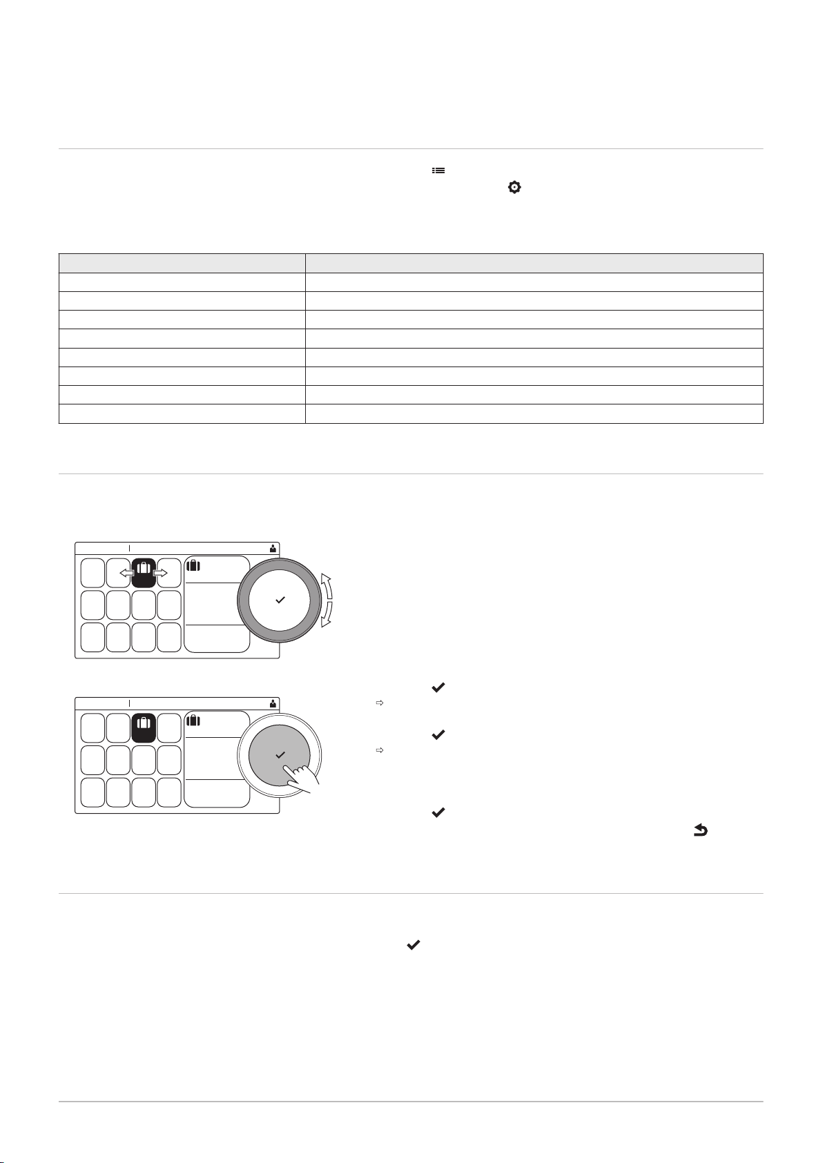
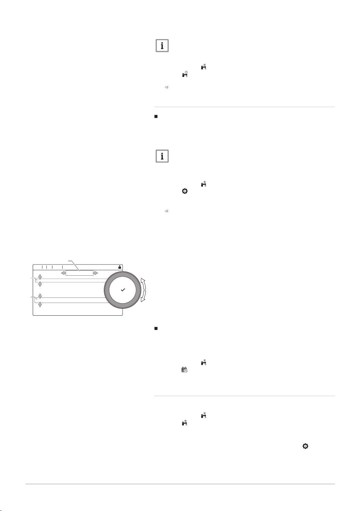
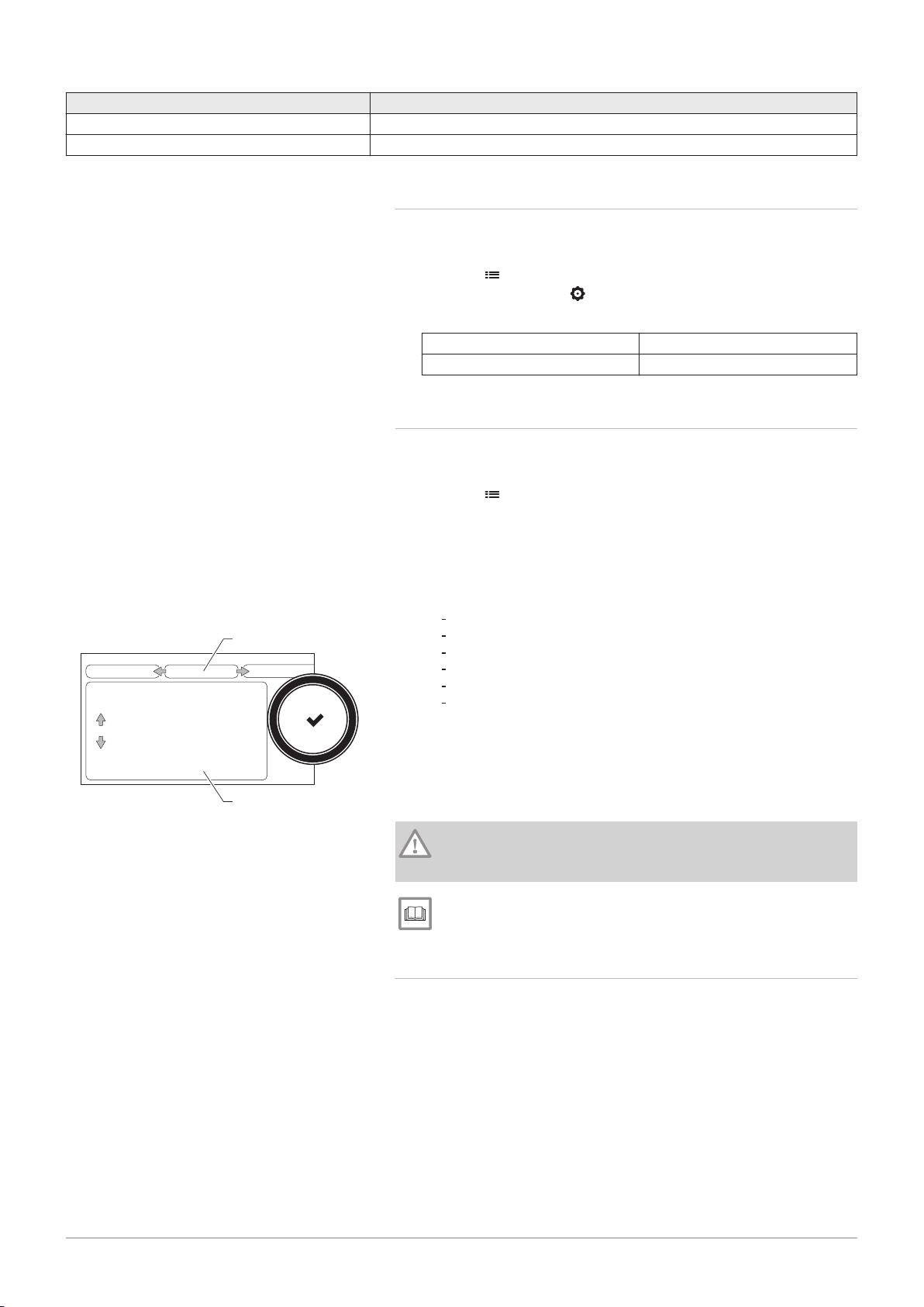
Fig.5
Fig.6 Confirm menu selection
Menu selection
The tiles on the home screen provide quick access for the user to the
corresponding menus.
1. Use the rotary knob to select the required menu.
2. Press the button to confirm the selection.
The available settings of this selected menu appear in the display.
3. Use the rotary knob to select the desired setting.
4. Press the button to confirm the selection.
All options for change will appear in the display (if a setting cannot
be changed, Cannot edit read-only datapoint will appear in the
display).
5. Use the rotary knob to change the setting.
6. Press the button to confirm the selection.
7. Use the rotary knob to select the next setting or press the button to
return to the home screen.
5.3
Home screen
The tiles on the home screen provide quick access to the corresponding
menus. Use the rotary knob to navigate to the menu of your choice and
press the button to confirm the selection. All options for change will
appear in the display (Cannot edit read-only datapoint will appear in the
display if a setting cannot be changed).
Page 11
Tab.5 Selectable tiles for the user
7725087 - v.01 - 06062019 AMC Pro 11
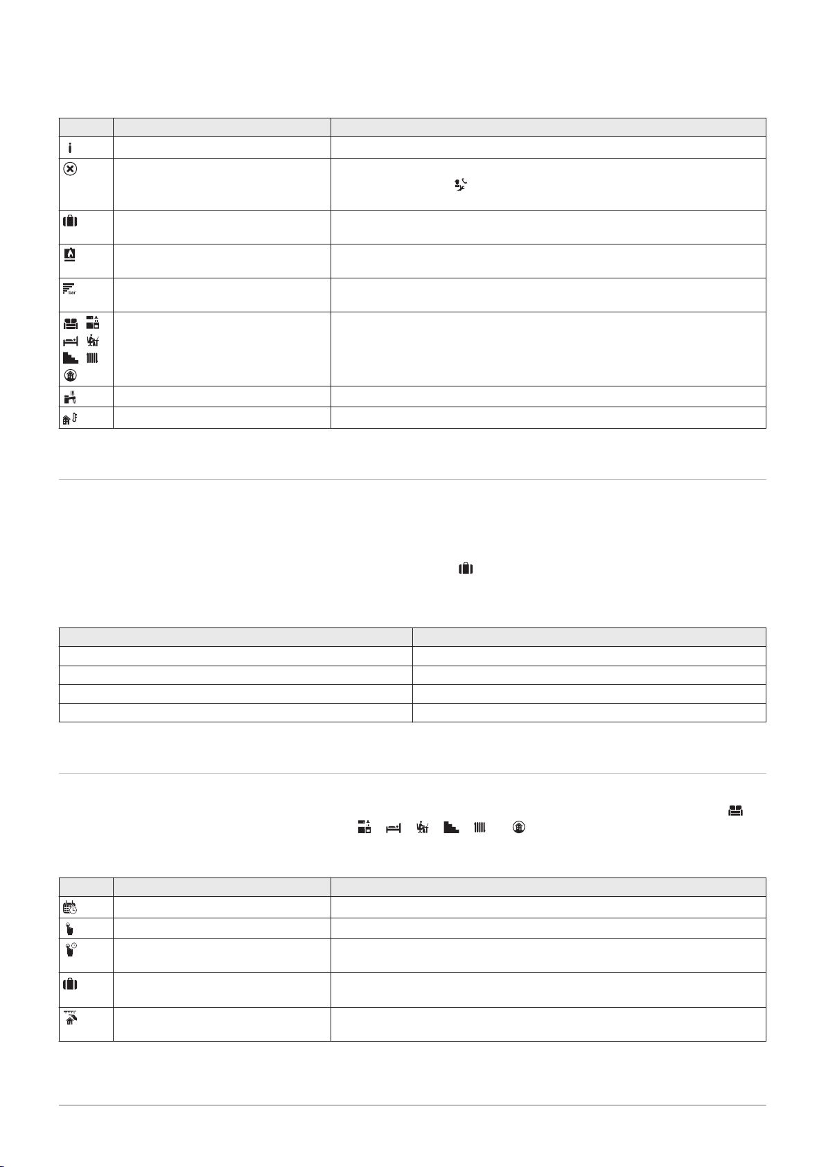
Tile Menu Function
Information menu. Read out various current values.
Error indicator. Read out details about the current error.
With some errors the icon will appear with installer contact details (when
filled in).
Holiday mode. Set the start and end date of your holiday to lower the room and domestic hot
water temperatures of all zones.
Gas boiler indicator. Read out burning details of the boiler and switch the heating function of the
boiler on or off.
Water pressure indicator. Shows the water pressure. Top up the installation when the water pressure is
too low.
Heating circuit set-up. Configure the settings per heating circuit.
, ,
, ,
, ,
DHW setup. Configure the domestic hot water temperatures.
Outdoor sensor setup. Configure the temperature regulation using the outdoor sensor.
5 User instructions
5.4 Activating holiday programs for all zones
If you go on holiday, the room temperature and domestic hot water
temperature can be reduced to save energy. With the following procedure
you can activate the holiday mode for all zones and domestic hot water
temperature.
1. Select the tile [ ].
2. Set the following parameters:
Tab.6 Holiday program settings
Parameter Description
Start date holiday Set the start time and date of your holiday
End date holiday Set the end time and date of your holiday
Wished room zone temperature on holiday period Set the room temperature for the holiday period
Reset Reset or cancel the holiday program
5.5 Heating circuit configuration
For every heating circuit there is a quick user settings menu available.
Select the heating circuit you want to configure by selecting the tile [ ],
[ ], [ ], [ ], [ ], [ ] or [ ]
Tab.7 Menu to configure a heating circuit
Icon Menu Function
Scheduling Set the scheduling mode and choose a timer program already created
Manual Set the manual mode; the room temperature setpoint is set to a fixed setting
Short temperature change Set the temporary mode; the room temperature setpoint is changed tempora
rily
Holiday Set the start and end date of your holiday to lower the room temperature set
point.
Antifrost Set the frost protection mode; the minimum room temperature protects your
system from freezing
Page 12
AD-3001404-01
1
2
5 User instructions
12 AMC Pro 7725087 - v.01 - 06062019
Icon Menu Function
Set Heating Activity Temperatures Set the room temperature setpoint for each activity of the timer program.
See: Timer program to control the room temperature, page 13
Zone configuration Access the settings for the configuration of the heating circuit.
Tab.8
Extended menu to configure a heating circuit Zone configuration
Menu Function
Short temperature change Change the room temperature temporarily, if required
OperatingZoneMode Select the heating operating mode: Scheduling, Manual or Antifrost
Manu ZoneRoomTempSet Set the room temperature manually to a fixed setting
Heating Schedule Create a timer program (up to 3 programs allowed). See: Creating a timer
program, page 13
Set Heating Activity Temperatures Set the room temperature for each activity of the timer program
ZoneTimeProg Select Select a timer program (3 options)
Holiday Mode Set the start and end date of your holiday and the reduced temperature for
this zone
Zone friendly Name Create or change the name of the heating circuit
Icon display zone Select the icon of the heating circuit
OperatingZoneMode Read the current operating mode of the heating circuit
5.6 Changing the room temperature of a zone
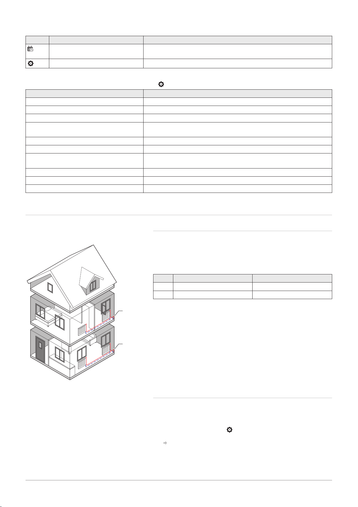
5.6.1 Definition of zone
Fig.7
Two zones
Zone is the term given to the different hydraulic circuits CIRCA, CIRCB
and so on. It designates several rooms of the house served by the same
circuit.
Tab.9 Example of two zones
Zone Factory name
1 Zone 1 CIRCA
2 Zone 2 CIRCB
5.6.2 Changing the name and symbol of a zone
The zones have a factory symbol and factory name. You can change the
name and symbol of a zone.
1. Select the tile of the zone you want to change.
2. Select Zone configuration
3. Select Zone friendly Name
A keyboard with letters, numbers and symbols is shown.
Page 13
AD-3001382-01
: .... ...... ........ ..............
11:20
xs t u v w
rm n o p q
fa b c d e
lg h i j k
y z
ÀÁÄabc ABC 123 !@# áäà
...
AD-3001383-01
: .... ...... ........ ..............
11:20
xs t u v w
rm n o p q
fa b c d e
lg h i j k
y z
ÀÁÄabc ABC 123 !@# áäà
...
5 User instructions
7725087 - v.01 - 06062019 AMC Pro 13
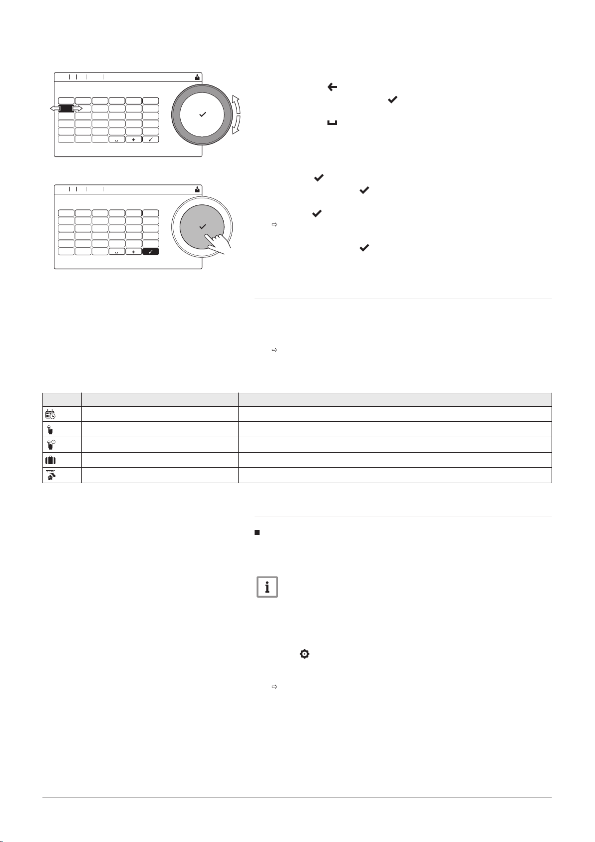
Fig.8
Letter selection
Fig.9 Confirm sign
4. Change the name of the zone (20 characters maximum):
4.1. Use the rotary button to select a letter, number or action.
4.2.
Select to delete a letter, number or symbol.
4.3.
Press the rotary knob to confirm or to repeat a letter,
number or symbol.
4.4.
Select to add a space.
5. Select the sign on the screen when the name is complete.
6. Press the rotary knob to confirm the selection.
7. Use the rotary button to select Icon display zone.
8. Press the knob to confirm the selection.
All available icons appear in the display.
9. Use the rotary knob to select the desired symbol of the zone.
10. Press the rotary knob to confirm the selection.
5.6.3 Changing the operating mode of a zone
To regulate the room temperature of the different areas of the house, you
can choose from 5 operating modes:
1. Select the tile of the zone you want to change.
The Zone QuickSelect menu opens.
2. Select the desired operating mode:
Tab.10 Operating modes
Icon Mode Description
Scheduling The room temperature is controlled by a timer program
Manual The room temperature is set to a fixed setting
Short temperature change The room temperature is changed temporarily
Holiday The room temperature is reduced during your holiday to save energy
Antifrost Protect the boiler and installation from freezing in winter
5.6.4 Timer program to control the room temperature
Creating a timer program
A timer program allows you to vary the room temperature per hour and per
day. The room temperature is linked to the activity of the timer program.
1. Select the tile of the zone you want to change.
2. Select Zone configuration > Heating Schedule.
3. Select the timer program you want to modify: Schedule 1, Schedule 2
or Schedule 3.
Important
You can create up to three timer programs per zone. For example,
you can create a program for a week with normal working hours
and a programme for a week when you are at home most of the
time.
Activities scheduled for Sunday are displayed. The last scheduled
activity of a day is active until the first activity of the next day. At
initial start-up, all weekdays have two standard activities; Home
starting at 6:00 and Sleep starting at 22:00.
Page 14
AD-3001403-01
0
15
20
25
°C
0:00 2:00 4:00 6:00 8:00 10:00 12:00h14:00 16:00 18:00 20:00 22:00 0:00
1
2
3
4
5
AD-3001384-01
........ .......
..... ... ....... ....
....... ...........
.... ...... ........ ..............
11:20
..:.. ........ ....
..:.. ........ ....
................ ..............
A
B
C
5 User instructions
14 AMC Pro 7725087 - v.01 - 06062019
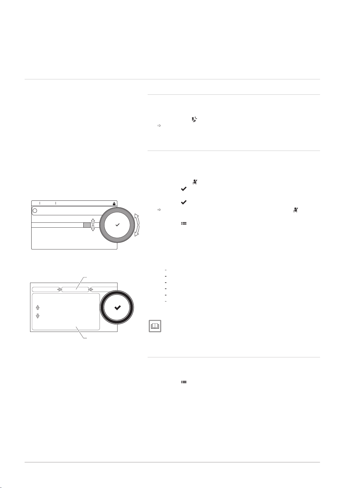
Fig.10
Weekday
4. Select the weekday you want to modify.
A Weekday
B Overview of scheduled activites
C List of actions
5. Perform the following actions, if necessary:
5.1. Edit the start time and/or activity of a scheduled activity.
5.2. Add a new activity.
5.3. Delete a scheduled activity (select the activity Delete).
5.4. Copy the scheduled activities of the weekday to other days.
5.5. Change the temperature linked to an activity.
Definition of activity
Activity is the term used when programming time slots in a timer program.
The timer program sets the room temperature for different activities during
the day. A temperature setpoint is associated with each activity. The last
activity of the day is valid until the first activity of the next day.
Fig.11
Activities of a timer program
Tab.11 Example of activities
Start of the activity Activity Temperature setpoint
1 6:30 Morning 20 °C
2 9:00 Away 19 °C
3 17:00 Home 20 °C
4 20:00 Evening 22 °C
5 23:00 Sleep 16 °C
Changing the name of an activity
You can change the names of the activities in the timer program.
1. Press the button.
2. Select System Settings .
3. Select Set Heating Activity Names.
A list of 6 activities and their standard names is shown:
Activity 1 Sleep
Activity 2 Home
Activity 3 Away
Activity 4 Morning
Activity 5 Evening
Activity 6 Custom
4. Select an activity.
A keyboard with letters, numbers and symbols is shown.
5. Change the name of the activity:
5.1.
Press the rotary knob to repeat a letter, number or symbol.
5.2.
Select to delete a letter, number or symbol.
5.3.
Select to add a space.
6. Select the sign on the screen when the name is complete.
7. Press the rotary knob to confirm the selection.
Page 15
5 User instructions
7725087 - v.01 - 06062019 AMC Pro 15
Activating a timer program
In order to use a timer program, it is necessary to activate the operating
mode Scheduling. This activation is done separately for each zone.
1. Select the tile of the zone you want to change.
2. Select Scheduling.
3. Select timer program Schedule 1, Schedule 2 or Schedule 3.
5.6.5 Changing the heating activity temperatures
You can change the heating temperatures of each activity.
1. Select the tile of the zone you want to change.
2. Select Set Heating Activity Temperatures.
A list of 6 activities and their temperatures is shown.
3. Select an activity.
4. Set the heating activity temperature.
5.6.6 Changing the room temperature temporarily
Regardless of the operating mode selected for a zone, it is possible to
change the room temperature for a short period. After this period has
elapsed, the selected operating mode resumes.
Important
The room temperature can only be adjusted in this way if a room
temperature sensor/thermostat is installed.
1. Select the tile of the zone you want to change.
2. Select Short temperature change.
3. Set the duration in hours and minutes.
4. Set the temporary room temperature.
The Short temperature change menu shows the duration and the
temporary temperature.
5.7 Changing the domestic hot water temperature
5.7.1 Changing the domestic hot water operating mode
For hot water production, you can choose from 5 operating modes:
1. Select the tile [ ].
The DHW QuickSelect menu opens.
2. Select the desired operating mode:
Tab.12 DHW operating modes
Icon Mode Description
Scheduling The domestic hot water temperature is controlled by a timer program
Manual The domestic hot water temperature is set to a fixed setting
Hot water boost The domestic hot water temperature is increased temporarily
Holiday The domestic hot water temperature is reduced during your holiday to save
energy
Antifrost Protect the boiler and installation from freezing in winter
5.7.2
Increasing the domestic hot water temperature temporarily
Regardless of the operating mode selected for domestic hot water
production, it is possible to increase the domestic hot water temperature
for a short period. After this period the hot water temperature decreases to
the Reduced setpoint.
Page 16
AD-3001384-01
........ .......
..... ... ....... ....
....... ...........
.... ...... ........ ..............
11:20
..:.. ........ ....
..:.. ........ ....
................ ..............
A
B
C
5 User instructions
16 AMC Pro 7725087 - v.01 - 06062019
Fig.12
Weekday
Important
The domestic hot water temperature can only be adjusted in this
way if a domestic hot water sensor is installed.
1. Select the tile [ ].
2. Select Hot water boost.
3. Set the duration in hours and minutes.
The temperature is increased to the DHW comfort setpoint.
5.7.3 Timer program to control the DHW temperature
Creating a timer program
A timer program allows you to vary the domestic hot water temperature
per hour and per day. The hot water temperature is linked to the activity of
the timer program.
Important
You can create up to three timer programs. For example, you can
create a program for a week with normal working hours and a
programme for a week when you are at home most of the time.
1. Select the tile [ ].
2. Select Zone configuration > DHW Schedule.
3. Select the timer program you want to modify: Schedule 1, Schedule 2
or Schedule 3.
Activities scheduled for Sunday are displayed. The last scheduled
activity of a day is active until the first activity of the next day. The
scheduled activities are shown. At initial start-up, all weekdays have
two standard activities; Comfort starting at 6:00 and Reduced
starting at 22:00.
4. Select the weekday you want to modify.
A
Weekday
B Overview of scheduled activites
C List of actions
5. Perform the following actions, if necessary:
5.1. Edit the start time and/or activity of a scheduled activity.
5.2. Add a new activity.
5.3. Delete a scheduled activity (select the activity Delete).
5.4. Copy the scheduled activities of the weekday to other days.
5.5. Change the temperature linked to an activity.
Activating a DHW timer program
In order to use a DHW timer program, it is necessary to activate the
operating mode Scheduling. This activation is done separately for each
zone.
1. Select the tile [ ].
2. Select Scheduling.
3. Select DHW timer program Schedule 1, Schedule 2 or Schedule 3.
5.7.4 Changing the comfort hot water temperature
You can change the comfort hot water temperature in the timer program.
1. Select the tile [ ].
2. Select DHW comfort setpoint: The DHW temperature when the hot
water production is switched on.
3. Set the comfort hot water temperature.
You can also change the reduced hot water temperature via: Zone
configuration > Domestic Hot Water Setpoints > DHW reduced setpoint:
The DHW temperature when the hot water production is switched off.
Page 17

5.8 Switching the central heating on or off
7725087 - v.01 - 06062019 AMC Pro 17
You can switch off the central heating function of the boiler to save energy,
for example during the summer period.
5 User instructions
1. Select the tile [ ].
2. Select CH function on.
3. Select the following setting:
3.1. Off to switch off the central heating function.
3.2. On to switch the central heating function on again.
Important
Frost protection is not available when the central heating function
is switched off.
5.9
Reading the installer's name and phone number
The installer can set his name and phone number in the control panel. You
can read this information when you want to contact the installer.
1. Press the button.
2. Select System Settings > .Installer Details
The installer’s name and phone number is shown.
Page 18
AD-3001378-02
00:12
0 1 2
3
4
0
1
5
6
2
0
3
4
5
1
2
3
4
1
2
3
4
0
........ .......
........ .......
........ ......... ...
..... ... ....... .... .. ..... ....... .... ..... .......
i
6 Installer instructions
18 AMC Pro 7725087 - v.01 - 06062019
6 Installer instructions
6.1 Accessing the installer level
Fig.13 Installer level
Some parameters that may affect the operation of the boiler are protected
by an access code. Only the installer is allowed to modify these
parameters.
1. Select the tile [ ].
2. Press the button to confirm the selection.
3. Use the rotary knob to select code: 0012.
4. Press the button to confirm the selection.
When the installer level is enabled, the status of the tile [ ]
changes from Off into On.
5. To leave the installer level, select the tile [ ] .
6. Use the rotary knob to select Confirm or Cancel.
7. Press the button to confirm the selection.
When the installer level is disabled, the status of the tile [ ]
changes from On into Off.
When the control panel is not used for 30 minutes, the installer level is left
automatically.
6.2 Configuring the installation at installer level
Configure the installation by pressing the button and selecting
Installation Setup . Select the control unit or circuit board you want to
configure:
Tab.13 CU-GH08
Icon Zone or function Description
CIRCA / CH Central heating circuit
Gas fired appliance Gas boiler
Tab.14 SCB-10
Icon Zone or function Description
CIRCA Central heating circuit A
CIRCB Central heating circuit B
DHW Domestic hot water external circuit
CIRCC Central heating circuit C
0-10 volt input 0–10 volt input signal
Digital Input Digital input signal
Analogue input Analogue input signal
Cascade management B Management of a cascade of multiple boilers
Buffer Tank Schedule Enable a buffer tank with one or two sensors
Outdoor temperature Outdoor sensor
Status information PCB SCB-10 status information
Tab.15 Configuring a zone or function of CU-GH08 or SCB-10
Parameters, counters, signals Description
Parameters Set the parameters at installer level
Counters Read the counters at installer level
Signals Read the signals at installer level
Adv. Parameters Set the parameters at advanced installer level
Page 19
Parameters, counters, signals Description
AD-3000936-01
A
B
7725087 - v.01 - 06062019 AMC Pro 19
Adv. Counters Read the counters at advanced installer level
Adv. Signals Read the signals at advanced installer level
6.2.1 Setting the installer details
You can store your name and phone number in the control panel to be
read by the user.
1. Press the button.
2. Select System Settings > Installer Details.
3. Enter the following data:
Installer name Name of the installer
Installer phone Phone number of the installer
6.2.2 Setting the parameters
You can change the parameters and settings of the appliance and the
connected control boards, sensors etc. to configure the installation.
1. Press the button.
2. Select > Installation Setup.
3. Select the zone or device you want to configure.
4. Select Parameters, counters, signals > Parameters to change a
parameter.
5. If available, select Adv. Parameters to change a parameter at the
advanced installer level.
A
Fig.14
Parameters, counters, signals
Parameters
Counters
Signals
Adv. Parameters
Adv. Counters
Adv. Signals
B List of settings or values
6 Installer instructions
The boiler’s control unit is set for the most common central heating
systems. These settings will ensure that virtually every central heating
system operates effectively. The user or the installer can optimise the
parameters as required.
Caution
Changing the factory settings may adversely affect the operation
of the boiler.
For more information, see
List of parameters, page 56
6.2.3 Changing boiler parameters when SCB-10 is fitted
When the boiler is fitted with the SCB-10 the following boiler CU-GH08
parameter(s) at installer level must be checked and adjusted, if necessary:
Page 20
AD-4100424-01
F
M
1500 2500 3500 4500 5500 6500 7500
0
20
R
Q
40
41,2
60
5400
AD-4100427-01
60
1500 2500 3500 4500 5500 6500 7500
0
20
R
Q
40
62
80
5600
F
M
6 Installer instructions
20 AMC Pro 7725087 - v.01 - 06062019
Tab.16 Installation Setup > CU-GH08 > CIRCA > Parameters, counters, signals > Parameters
Code Display text Description Range Adjust
ment
CP020 Zone Function Functionality of the zone 0 = Disable
0
1 = Direct
2 = Mixing Circuit
3 = Swimming pool
4 = High Temperature
5 = Fan Convector
6 = DHW tank
7 = Electrical DHW
8 = Time Program
9 = ProcessHeat
10 = DHW Layered
11 = DHW Internal tank
31 = DHW FWS EXT
Tab.17 Installation Setup > CU-GH08 > Gas fired appliance > Parameters, counters, signals > Parameters
Code Display text Description Range Adjust
ment
AP102 Boiler Pump function Configuration of the boiler pump as
zone pump or system pump (feed
0 = No
1 = Yes
0
lowloss header)
Tab.18 Installation Setup > CU-GH08 > Tank DHW > Parameters, counters, signals > Parameters
Code Display text Description Range Adjust
ment
DP007 Dhw 3wv Standby Position of three way valve during
standby
6.2.4
Setting the maximum load for CH operation
0 = CH position
1 = DHW position
0
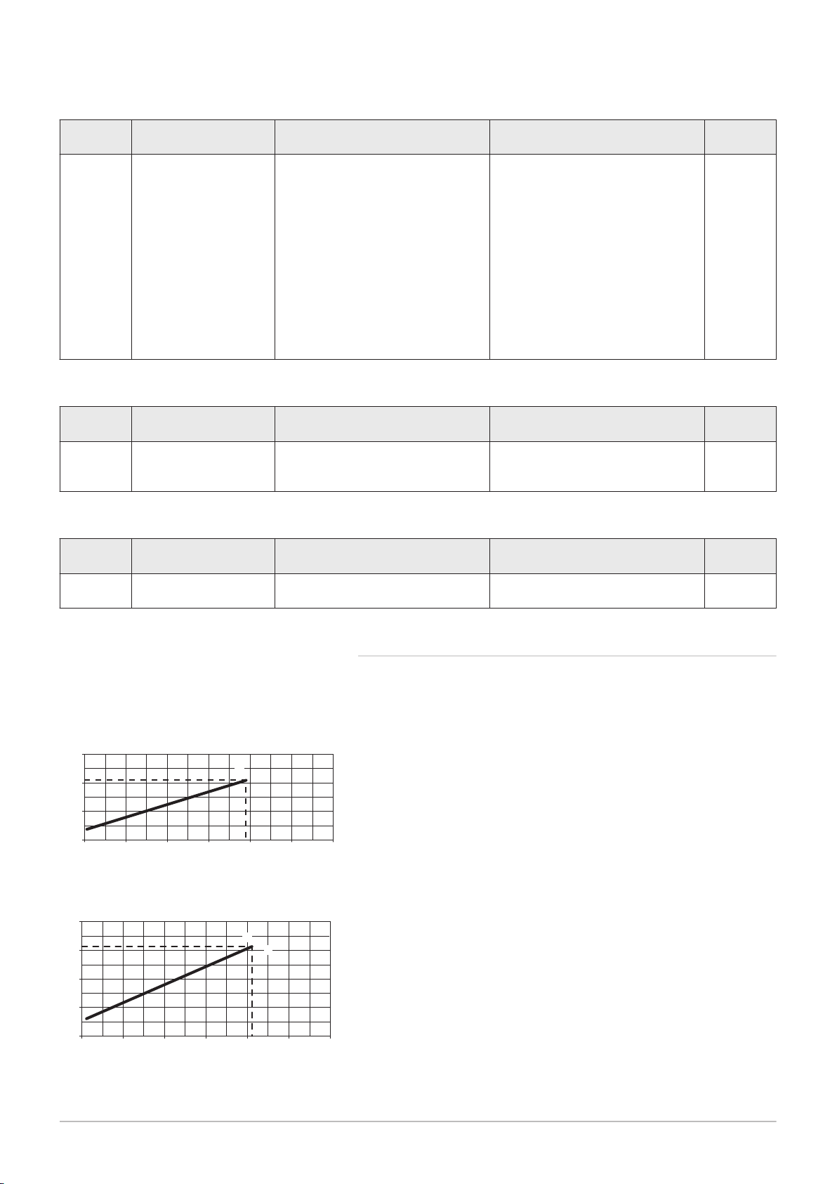
See the graphs for the relationship between load and speed for natural
gas. The speed can be changed using parameter GP007.
Fig.15 Load AMC Pro 45
Fig.16 Load AMC Pro 65
M
Maximum heat input
F
Factory setting
Q
Input (Hi) (kW)
R
Fan speed (rpm)
M
Maximum heat input
F
Factory setting
Q
Input (Hi) (kW)
R
Fan speed (rpm)
Page 21
AD-4100429-01
1500 2500 3500 4500 5500 6500 7500
0
20
R
Q
40
60
80
86
100
6300
F
M
AD-4100431-01
1500 2500 3500 4500 5500 6500 7500
0
20
R
Q
40
60
80
100
107
120
6800
F
M
AD-3001402-01
.... ...... ........ ..............
11:20
.... ...
... ....
...... ...
... ...
........ ...................
........ ...................
.... .....
D
B
A
C
6 Installer instructions
7725087 - v.01 - 06062019 AMC Pro 21
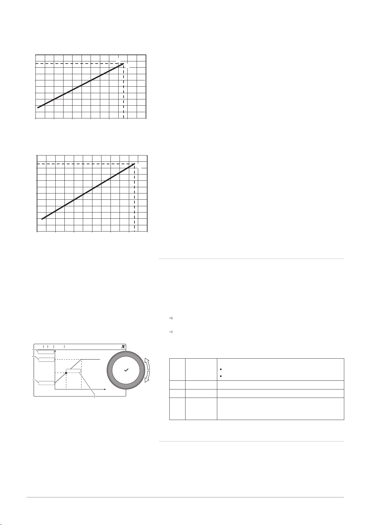
Fig.17
Load AMC Pro 90
Fig.18 Load AMC Pro 115
M
Maximum heat input
F
Factory setting
Q
Input (Hi) (kW)
R
Fan speed (rpm)
M
Maximum heat input
F
Factory setting
Q
Input (Hi) (kW)
R
Fan speed (rpm)
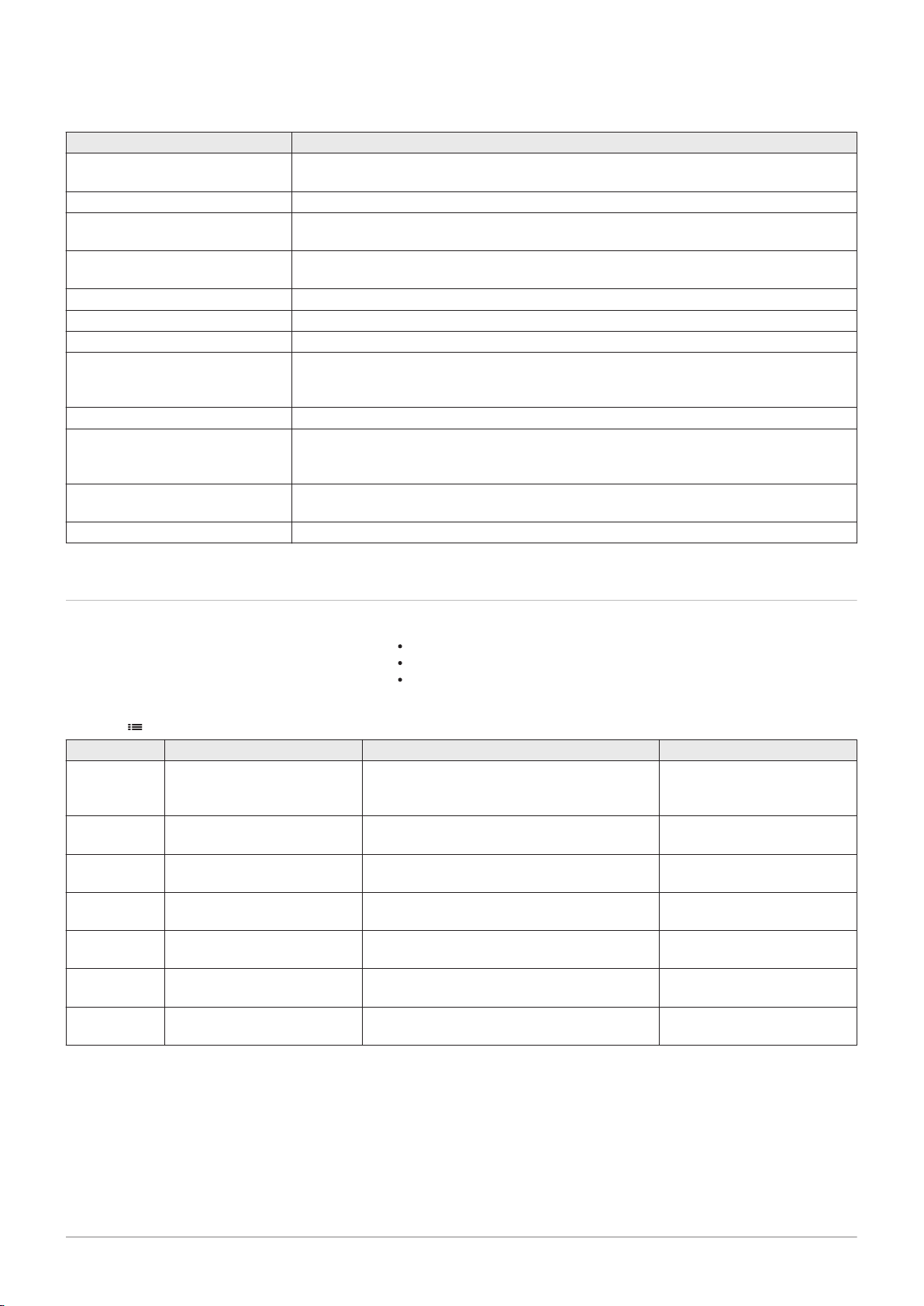
6.2.5 Setting the heating curve
When an outdoor temperature sensor is connected to the installation, the
relation between the outdoor temperature and the central heating flow
temperature is controlled by a heating curve. This curve can be adjusted
to the requirements of the installation.
1. Select the tile of the zone you want to configure.
2. Select Control strategy.
3. Select the setting Outdoor Temp. based or Outdoor & room based.
The option Heating Curve appears in the Zone setup menu.
4. Select Heating Curve.
A graphic display of the heating curve is shown.
Fig.19 The heating curve
5. Adjust the following parameters:
Tab.19 Settings
A Slope: Slope of the heating curve:
Floor heating circuit: slope between 0.4 and 0.7
Radiator circuit: slope at approximately 1.5
B Max: Maximum temperature of the heating circuit
C Base: Ambient temperature setpoint
D xx°C ; xx°CRelationship between the heating circuit flow
temperature and the outdoor temperature. This
information is visible throughout the slope.
6.2.6 Screed drying
The screed drying function is used to force a constant flow temperature or
a series of successive temperature levels to accelerate screed drying on
underfloor heating.
Page 22
AD-3001406-01
0
20
35
50
T
0:00 0:00 0:00 0:00 0:00 0:00 0:00
d
0:00 0:00 0:00 0:00 0:00 0:00
10
9 8 7 6 5
4
3 2 1 x x
2
3
4 5
1
AD-3000941-02
A
B
6 Installer instructions
22 AMC Pro 7725087 - v.01 - 06062019
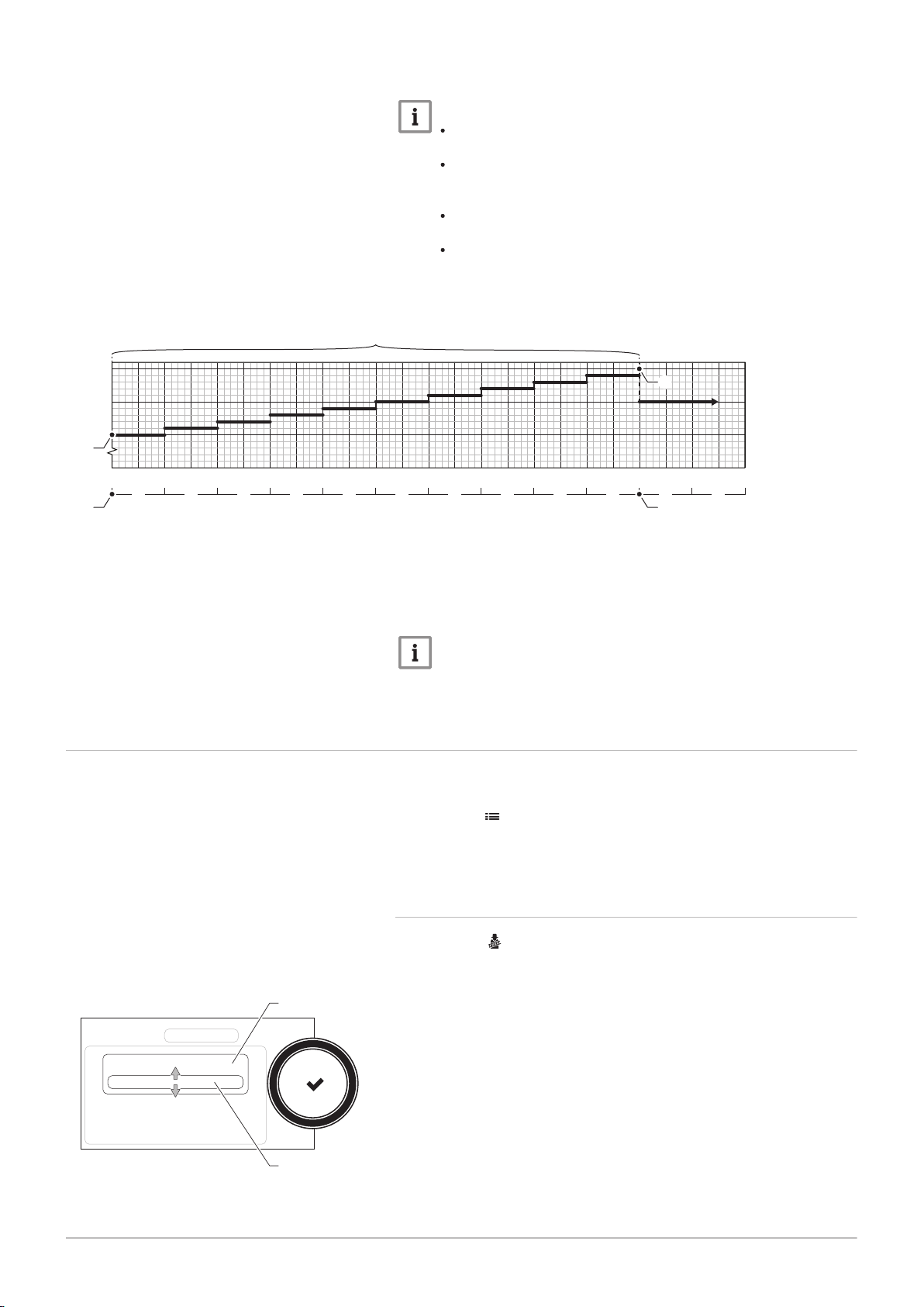
Fig.20 Screed drying curve
Important
The settings for these temperatures must follow the screed
layer's recommendations.
Activation of this function via the parameter CP470 forces the
permanent display of the screed drying function and deactivates
all other regulator functions.
When the screed drying function is active on one circuit, all
other circuits and the domestic hot water circuit continue to run.
It is possible to use the screed drying function on circuits A and
B. The parameter settings must be made on the PCB that
controls the circuit concerned.
d
Number of days
T
Heating set point temperature
1
Number of days on which the screed drying function
is activated (parameter CP470)
2
Screed drying start temperature (parameter CP480)
6.3 Commissioning the installation
Fig.21 Load test
3
Screed drying stop temperature (parameter CP490)
4
Start of the screed drying function
5
End of the screed drying function, back to normal
running
Important
Every day at midnight, the screed drying start temperature set
point is recalculated and the remaining number of days on which
the screed drying function is running decreases.
The commissioning menu shows submenus and tests needed for the
commissioning of the appliance.
1. Press the button.
2. Select Commissioning Menu.
3. Select the submenu with settings you want to change or the test you
want to perform.
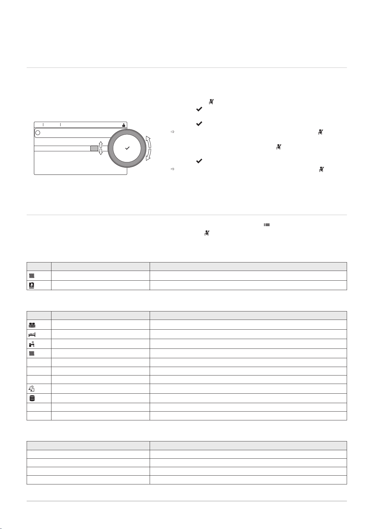
6.3.1
Chimney sweep menu
Select the tile [ ] to open the chimney sweep menu. The Change load
test mode menu will appear:
A Change load test mode
B Load test mode
Page 23
AD-3000941-02
A
B
AD-3000941-02
A
B
6 Installer instructions
7725087 - v.01 - 06062019 AMC Pro 23
Tab.20
Load tests in the chimney sweep menu
Change load test mode Settings
Off No test
MinimumPower Part load test
MaximumPowerCH Full load test for Central Heating mode
MaximumPowerDhw Full load test for Central Heating + Domestic Hot Water mode
Tab.21 Load test settings
Load Test menu Settings
ChimneyModeStatus Select the load test to start the test.
System Flow Temp Read the central heating flow temperature
T return Read the central heating return temperature
Actual fan RPM Read the actual fan speed
Actual flame current Read the actual flame current
Fan RPM Max CH Adjust the maximum fan speed during Central Heating mode
Fan RPM Min Adjust the minimum fan speed during Central Heating + Domestic Hot Water mode
Fan RPM Start Adjust the start fan speed
Performing the full load test
1. Select the tile [ ].
The Change load test mode menu appears.
2. Select the test MaximumPowerCH.
A
Fig.22
Full load test
Change load test mode
B MaximumPowerCH
The full load test starts. The selected load test mode is shown in the
menu and the icon appears in the top right of the screen.
3. Check the load test settings and adjust if necessary.
Only the parameters shown in bold can be changed.
Fig.23 Part load test
Performing the part load test
1. If the full load test is still running, press the button to change the
load test mode.
2. If the full load test was finished, select the tile [ ] to restart the
chimney sweep menu.
Change load test mode
A
B MinimumPower
3. Select the MinimumPower test in the menu Change load test mode.
The part load test starts. The selected load test mode is shown in
the menu and the icon appears in the top right of the screen.
4. Check the load test settings and adjust if necessary.
Only the parameters shown in bold can be changed.
5. End the part load test by pressing the button.
The message Running load test(s) stopped! is displayed.
6.3.2 Saving the commissioning settings
You can save all current settings on the control panel. These settings can
be restored if necessary, for example after replacement of the control unit.
1. Press the button.
Page 24
AD-3001378-02
00:12
0 1 2
3
4
0
1
5
6
2
0
3
4
5
1
2
3
4
1
2
3
4
0
........ .......
........ .......
........ ......... ...
..... ... ....... .... .. ..... ....... .... ..... .......
i
AD-3000936-01
A
B
6 Installer instructions
24 AMC Pro 7725087 - v.01 - 06062019
2. Select > Advanced Service Menu > Save as commissioning settings.
3. Select Confirm to save the settings.
When you have saved the commissioning settings, the option Revert
commissioning settings becomes available in the Advanced Service Menu.
6.4
Fig.24
Maintaining the installation
Installer level
Fig.25 Parameters, counters, signals
6.4.1 Viewing the service notification
When a service notification appears on the display, you can view the
details of the notification.
1. Select the tile [ ].
The View Service Notification menu opens.
2. Select the parameter or value you want to view.
6.4.2 Reading out measured values
The control unit continually registers various values from the boiler and the
connected sensors. These values can be read on the control panel of the
boiler.
1. Select the tile [ ].
2. Press the button to confirm the selection.
3. Use the rotary knob to select code: 0012.
4. Press the button to confirm the selection.
When the installer level is enabled, the status of the tile [ ]
changes from Off into On.
5. Press the button.
6. Select > Installation Setup.
7. Select the zone or device you want to read out.
8. Select Parameters, counters, signals > Counters or Signals to read
out a counter or signal.
9. If available, select Adv. Counters or Adv. Signals to read out counters
or signals at the advanced installer level.
A
Parameters
Counters
Signals
Adv. Parameters
Adv. Counters
Adv. Signals
B List of settings or values
For more information, see
List of measured values, page 77
6.4.3 Viewing production and software information
You can read details about the production dates, hardware and software
versions of the appliance and all connected devices.
1. Press the button.
2. Select Version Information.
Page 25
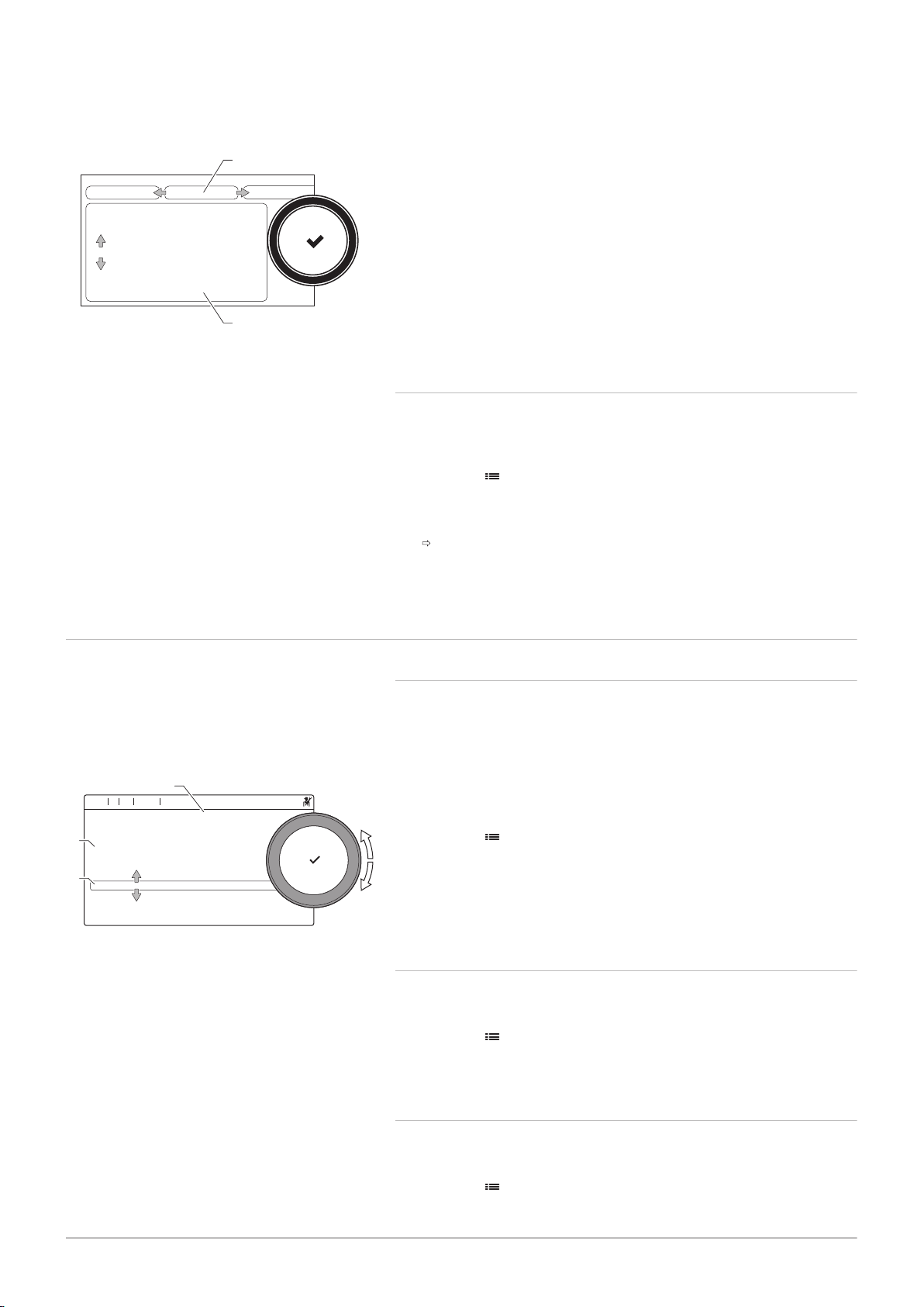
Fig.26
AD-3000936-01
A
B
AD-3001385-01
.... ...... ........ ..............
11:20
........
... .
... .
............ ....... ....... ....
......... ... .............. ...... .. .....
.......
.......
A
B
C
7725087 - v.01 - 06062019 AMC Pro 25
Version information
6 Installer instructions
3. Select the appliance, control board or any other device you want to
view.
A Select the appliance, control board or device
B List of information
4. Select the information you want to view.
6.4.4 Changing the domestic hot water temperature temporarily
When the timer program is active with a reduced domestic hot water
temperature, you can temporarily increase the hot water temperature for
e.g. testing of the hot water production.
1. Press the button.
2. Select Installation Setup > Internal DHW > Hot water boost.
3. Select Duration of temporary overwrite .
4. Set the duration in hours and minutes.
The hot water temperature is increased to the DHW comfort
setpoint.
You can delete or abort the temporary overwrite by selecting Reset.
6.5 Resetting or restoring settings
Fig.27 Configuration numbers
6.5.1
Resetting the configuration numbers CN1 and CN2
The configuration numbers must be reset when indicated by an error
message or when the control unit has been replaced. The configuration
numbers can be found on the data plate of the appliance.
A Select the control unit
B Extra information
C Configuration numbers
1. Press the button.
2. Select Advanced Service Menu > Set Configuration Numbers.
3. Select the control unit you want to reset.
4. Select and change the CN1 setting.
5. Select and change the CN2 setting.
6. Select Confirm to confirm the changed numbers.
6.5.2 Carrying out an auto-detect for the CAN matrix
When a control board has been replaced or removed from the boiler, this
function must be used to detect all devices connected to the CAN bus.
1. Press the button.
2. Select Advanced Service Menu > Auto Detect.
3. Select Confirm to carry out the auto-detect.
6.5.3
Restoring the commissioning settings
This option is only available when the commissioning settings were saved
on the control panel and allows you to restore these settings.
1. Press the button.
2. Select Advanced Service Menu > Revert commissioning settings.
3. Select Confirm to restore the commissioning settings.
Page 26

6 Installer instructions
26 AMC Pro 7725087 - v.01 - 06062019
6.5.4 Resetting to factory settings
You can reset the boiler to the default factory settings.
1. Press the button.
2. Select Advanced Service Menu > Reset to Factory Settings.
3. Select Confirm to restore the factory settings.
Page 27

7 Installation examples
AD-3001210-01
X2 X3
+TA-
TA
Tsyst Tsyst Tdhw Tflow Tflow Tflow
C AB21
R-Bus
Tout
R-Bus
R-Bus
12
3
4
+ -
Status
C AB
0-10V
N L
B
N
N L TS
N L
TS
A
N
23
2218 2019 21
5
14131211 15 16 17
43
21
109876
AD-4000062-01
x3
1
2
7725087 - v.01 - 06062019 AMC Pro 27
7.1 Access to the expansion box
7 Installation examples
Fig.28 Access to the expansion box
7.2
Connection options for the expansion PCB - SCB-10
If there is no space in the boiler’s instrument box to install an (optional)
expansion PCB, install the PCB in the electronics expansion box This is
available as an accessory.
1. Unclip the housing cover.
2. Remove the cover.
3. Install the expansion PCB in accordance with the instructions
supplied.
The following is installed in the expansion box:
the SCB-10 PCB.
Different heating zones can be connected to the SCB-10 PCB.
control of 2 (mixing) zones fitted on connector X15
control of a third (mixing) zone via an PCB (= accessory) fitted on
connector X8
control of one domestic hot water (DHW) zone
cascade layout (add sensor on sensor system 1 or 2)
Important
If the boiler is fitted with the SCB-10 PCB, then this is
automatically recognised by the automatic control unit of the
boiler.
On removing this control board, the boiler will show an error
code. To prevent this error, carry out an auto-detect immediately
after removing this board.
Fig.29 SCB-10 PCB
1 Outdoor temperature sensor
2 Programmable and 0-10 V input
3 Room temperature sensor - circuit C
4 Room temperature sensor - circuit B
Page 28
AD-3001318-01
X2 X3
7 Installation examples
28 AMC Pro 7725087 - v.01 - 06062019
5 Room temperature sensor - circuit A
6 Domestic hot water tank pump
7 Mixing valve - circuit B
8 Pump and safety thermostat - circuit B
9 Mixing valve - circuit A
10 Pump and safety thermostat - circuit A
11 System sensor 1
12 System sensor 2
13 Domestic hot water sensor
14 Flow sensor - circuit C
7.3
Zone functions of SCB-10
15 Flow sensor - circuit B
16 Flow sensor - circuit A
17 Impressed current anode
18 Connectors Mod-BUS
19 Coding wheel, selects the generator number in the
cascade in Mod-Bus
20 S-BUS connector
21 END connector for L-BUS connection
22 L-BUS connection to control unit (CU-GH08)
23 S-BUS cable connector
The SCB-10 with the AD249 option has following basic functions with
default zone settings:
CIRCA1 with parameter CP020 set as Direct circuit
CIRCB1 with parameter CP021 set as Disable
DHW1 with parameter CP022 set as Disable
CIRCC1 with parameter CP023 set as Disable
AUX1 with parameter CP024 set as Disable
To configure your specific installation, make sure to check and adjust the
parameter settings for the selected zones. The zone function table shows
which parameter settings are available for which zones.
Tab.22 Parameter setting for zone function
Zone
Parameter to set zone function
CIRCA 1
CP020
(1)
(3)
CIRCB 1
CP021
(1)
(3)
DHW 1
CP022
(1)
(3)
CIRCC 1
CP023
(1)(2)
(3)
AUX 1
CP024
0 = Disable x x x x x
1 = Direct x x x
2 = Mixing Circuit x x x
3 = Swimming pool x x x
4 = High Temperature x x x
5 = Fan Convector x x x
6 = DHW tank x x x x x
7 = Electrical DHW x x x
8 = Time Program x x x x x
9 = ProcessHeat x x x x x
10 = DHW Layered x
11 = DHW Internal tank x x x x x
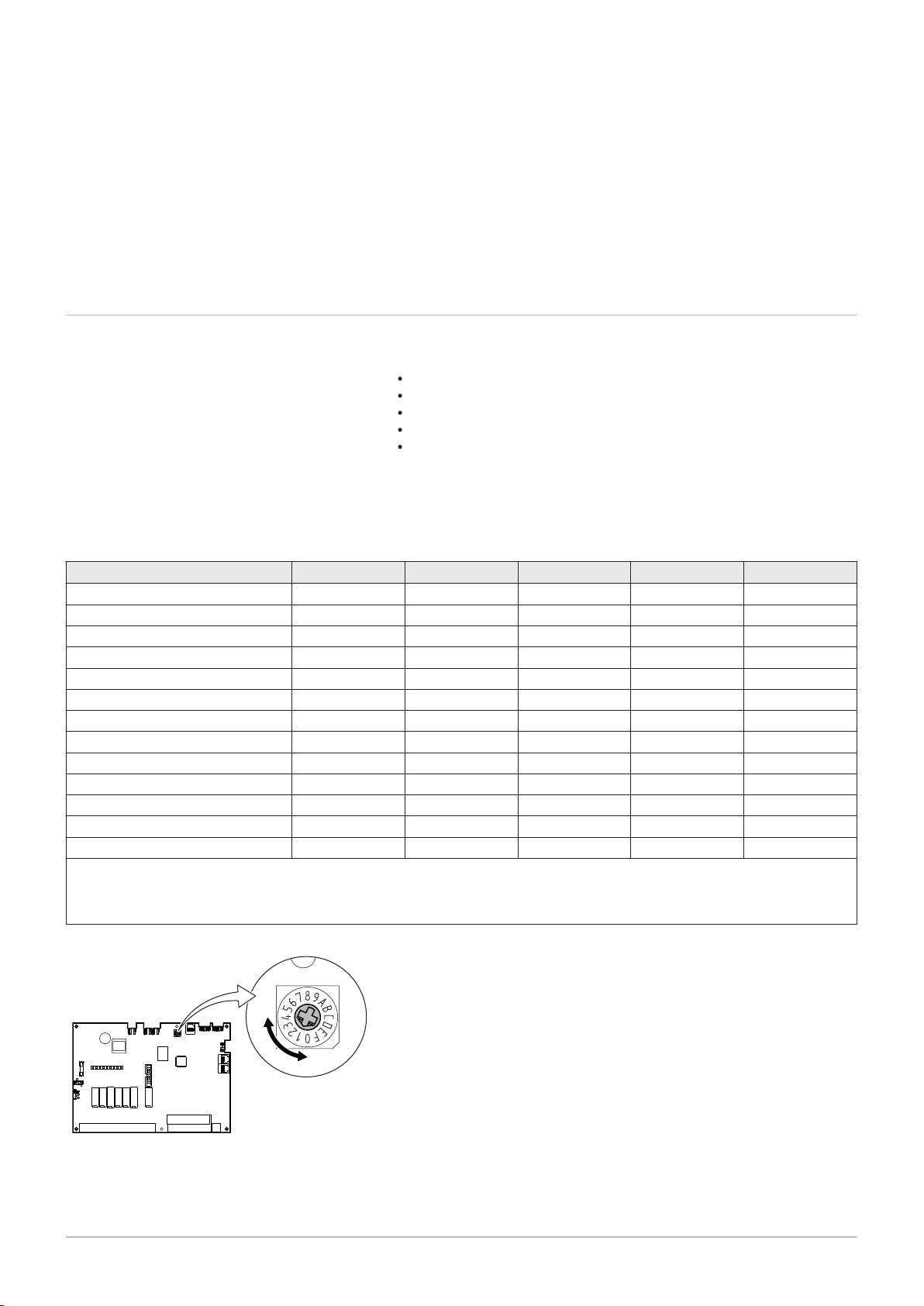
(1) The number refers to the circuit number which can be set with the rotary dial on the SCB-10.
(2) With AD249 option.
(3) The last number of the parameter is related to the zone. The code can be used to identify the parameter settings in the connection
examples.
(1)(2)
(3)
Fig.30
Rotary dial
You can use the rotary dial to identify multiple SCB-10s, for example in a
cascade situation. The default position of the rotary dial is 1. In this case
zone A will appear in the display as CIRCA1 (circuit A 1).
Page 29
7 Installation examples
7725087 - v.01 - 06062019 AMC Pro 29
Tab.23 Zone function settings explanation
Zone setting Explanation
0 = Disable Removes the circuit display, the circuit is not used, but its pump output can be used as a
status output.
1 = Direct Setting to manage a heating pump on the selected zone, cooling is not possible.
2 = Mixing Circuit Setting to manage a valve and a pump with the flow sensor, in heating or cooling (exam
ple underfloor heating).
3 = Swimming pool Setting to manage the pool heat pump according to the flow sensor (if the sensor is
present) and also the pool filter pump.
4 = High Temperature Setting to manage a pump, heats 365 days with program time, no stop in summer
5 = Fan Convector Setting to manage a pump, to warm and refresh
6 = DHW tank Setting to manage a pump and a sensor for domestic hot water
7 = Electrical DHW Setting to manage a pump, a sensor and to use the valve connector to control a relay for
the electric resistance of the tank. When switching to summer mode the tank automatical
ly switches to electric.
8 = Time Program Setting to create a time schedule on the pump connectors.
9 = ProcessHeat Setting to manage a pump, heats 365 days 24/24, no stop in summer, priority on all cir
cuits. The boiler will remove all protections to produce maximum power in a minimum of
time
10 = DHW Layered Setting to manage domestic hot water with 2 sensors, a tank top sensor (Tsyst 1 or 2)
triggers the load and the bottom sensor of the tank (Tdhw) triggers the stop of the charge.
11 = DHW Internal tank Setting to manage domestic hot water for boilers with internal tank.
7.4 Setting the 0-10 Volt input function of SCB-10
There are three options for the 0-10 Volt input control of the SCB-10 print:
disable the input function.
the input is temperature based.
the input is heat output based
Tab.24
Code Display text Description Range
EP014 SCB func. 10V PWMin Smart Control Board function 10 Volt PWM
EP030 Min Setp Temp 0-10V Sets the minimum set point temperature for 0
EP031 Max Setp Temp 0-10V Sets the maximum set point temperature for 0
EP032 Min Setp Power 0-10V Sets the minimum set point power for 0 - 10
EP033 Max Setp Power 0-10V Sets the maximum set point power for 0 - 10
EP034 Min Setp Volt 0-10V Sets the minimum set point voltage for 0 - 10
EP035 Max Setp Volt 0-10V Sets the maximum set point voltage for 0 - 10
button > Installation Setup > SCB-10 > 0-10 volt input > Parameters
input
- 10 volts for the Smart Control Board
- 10 volts for the Smart Control Board
volts for the Smart Control Board
volts
volts for the Smart Control Board
volts
0 = Off
1 = Temperature control
2 = Power control
0 °C - 100 °C
0.5 °C - 100 °C
0 % - 100 %
5 % - 100 %
0 V - 10 V
0 V - 10 V
Page 30
AD-0001156-02
0
1 2 3 4 5
6
7 8
9
10
0 - 10 V
10
20
30
40
50
60
70
80
90
100
2
3
4
1
AD-3000964-01
B CA
7 Installation examples
30 AMC Pro 7725087 - v.01 - 06062019
7.4.1 Analogue temperature regulation (°C)
Fig.31 Temperature regulation
1 Boiler on
2 Parameter CP010
3 Maximum flow temperature
4 Calculated value
The 0–10 V signal controls the boiler supply temperature. This control
modulates on the basis of flow temperature. The output varies between
the minimum and maximum value on the basis of the flow temperature set
point calculated by the controller.
Tab.25 Temperature regulation
Input signal (V) Temperature °C Description
0–1.5 0–15 Boiler off
1.5–1.8 15–18 Hysteresis
1.8–10 18–100 Desired temperature
7.4.2 Analogue output-based control
The 0 - 10 V signal controls the boiler output. This control modulates on
the basis of the heat output. The minimum output is linked to the boiler's
modulation depth. The output varies between the minimum and maximum
value on the basis of the value defined by the controller.
Tab.26 Control based on heat output
Input signal (V) Heat output (%) Description
0–2.0 0 Boiler off
2.0–2.2 0 Heat demand
2.0–10 0–100 Desired heat output
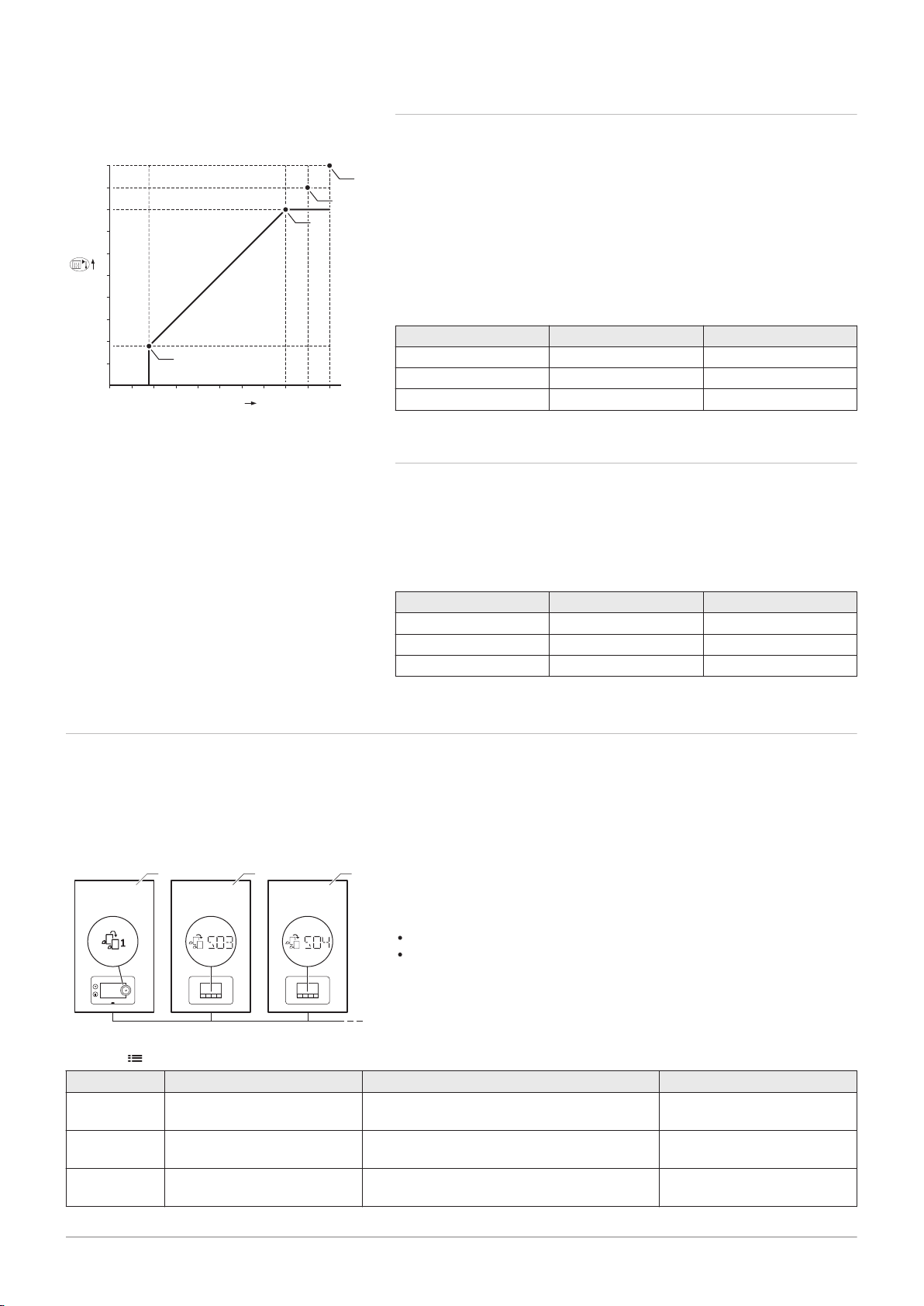
7.5 Cascade control
With the Diematic Evolution mounted in the master boiler it is possible to
manage up to 7 boilers equipped with the Inicontrol 2 in cascade. The
system sensor is connected to the master boiler. All the boilers in the
cascade are connected by an S-BUS cable. The boilers are automatically
numbered:
Fig.32 Cascade numbering
Tab.27
Code Display text Description Model series
NP006 Cascade Type Cascading boilers by adding successively or
NP009 CascInterStageTime Switch on and switch off timing for the
NP011 CascadeTypeAlgo Choice of Cascade Algorithm type, power or
> Installation Setup > SCB-10 > Cascade management B > Parameters, counters, signals > Parameters
in parallel, the boilers function simultaneously
producer of the cascade
temperature
A
The master boiler is number 1.
B
The first slave boiler is number 3 (number 2 does not exist).
C
The second slave boiler is number 4; and so on.
There are two options for cascade control management:
Adding supplementary boilers successively (traditional control).
Adding supplementary boilers simultaneously (parallel control).
0 = Traditional
1 = parallel
1 Min - 60 Min
0 = Temperature
1 = Power
Page 31

AD-3000960-01
40 8
4
x 8
-3K
+3K
6
5
4
1
2
3
AD-3000961-01
40 8
4
x 8
-3K
+3K
4
3
2
1
7 Installation examples
7725087 - v.01 - 06062019 AMC Pro 31
Fig.33 Traditional cascade control
management
Fig.34 Parallel cascade control
management
1
First boiler starts running when system temperature is 3°C below
set point.
2
After 4 minutes the second boiler starts running if ΔT< 6K and the
system temperature is still more than 3°C below set point.
3
After 8 minutes the third boiler starts running if ΔT< 6K and the
system temperature is still more than 3°C below set point.
4
First boiler stops running when system temperature is 3°C above
set point.
5
After 4 minutes the second boiler stops running if ΔT< 6K and the
system temperature is still more than 3°C above set point.
6
After 8 minutes the third boiler stops running if ΔT< 6K and the
system temperature is still more than 3°C above set point.
1
All boilers in cascade start running when system temperature is
3°C below set point.
2
First boiler stops running when system temperature is 3°C above
set point.
3
After 4 minutes the second boiler stops running if ΔT< 6K and the
system temperature is still more than 3°C above set point.
4
After 8 minutes the third boiler stops running if ΔT< 6K and the
system temperature is still more than 3°C above set point.
Temperature type cascade algorithm; the setpoint sent to the running
boiler is:
Output; requested by the zones.
Temperature; output setpoint requested by the zones + error calculation.
Output type cascade algorithm; the setpoint sent to the running boiler is:
Output; according to PI algorithms.
Temperature; -90°C
7.6 Connecting diagrams
7.6.1 Symbols used
Tab.28 Explanation of symbols in the hydraulics flow diagram
Symbol Explanation
Return pipe
Flow pipe
Mixing valve
Pump
Domestic hot water
Make contact
Outdoor temperature sensor
Sensor
Safety thermostat
Room thermostat
Plate heat exchanger
Page 32

7 Installation examples
32 AMC Pro 7725087 - v.01 - 06062019
Symbol Explanation
Safety group
Low-loss header
Instant boiler
Primary heating circuit connection
Solar collector
Domestic hot water storage tank
Titanium anode
(1)
Electrical heating element
Shower
Heating zone
Underfloor heating
Underfloor heating manifold
Hot-air heater
Swimming pool
(1) Fitted in domestic hot water storage tank.
Page 33

7.6.2 Connection example 1
AD-4100034-01
A
1
B
2
C
3
4
AD-4100147-01
6.3A T
X12
X13
X15
S-BUS
X1
X9 X11
X2 X3
X4
X5
X10
RS
SP
L-BUS
SCB-10
X14
X8
N L
B
N
N L TS
N L
A
N
TS
C
R-BusBR-Bus
A
+TA-
TA
1 2 C B A
Tsyst Tsyst Tdhw TflowTflow Tflow
R-Bus
Tout
BL
RL
Tdhw
CB-03
X131 X136
X4
X03
T out
Status
R-Bus
12
3
4
+
0-10V
-
X14
3 412
A
7725087 - v.01 - 06062019 AMC Pro 33
Fig.35 1 boiler + 1 direct zone + domestic hot water (DHW) zone
7 Installation examples
A
Boiler
B
Direct zone-CircA1
C
Important
All the factory settings of the SCB-10 are adequate for this
connection.
Domestic Hot water zone-DHW (1 sensor )
Page 34

AD-4100035-01
A
M
5
T
3
4
C
2
1
B
AD-4100137-01
6.3A T
X12
X13
X15
X9 X11
X2 X3
X10
RS
SP
L-BUS
SCB-10
X14
X8
+TA-
TA
1 2 C AB
Tsyst Tsyst Tdhw Tflow Tflow Tflow
X14
N LBN
N L TS
N L
A
N
TS
T out
Status
R-Bus
12
3
4
+
0-10V
-
C
R-BusBR-Bus
A
X1
S-BUS
X4
X5
R-Bus
Tout
BL
RL
Tdhw
CB-03
X131 X136
X4
X03
31245
A
7 Installation examples
34 AMC Pro 7725087 - v.01 - 06062019
Fig.36 1 boiler + 1 direct zone + 1 mixing zone
7.6.3 Connection example 2
A
Important
All the factory settings of the SCB-10 are adequate for this
connection.
Mixing zone - CircB1
A
Boiler
B
Direct zone - CircA1
Page 35

7.6.4 Connection example 3
AD-4100036-01
1
A
3
2
4
B
5
C
6
AD-4100138-01
6.3A T
X12
X13
X15
S-BUS
X1
X9
X11
X2
X3
X4
X5
X10
RS
SP
L-BUS
SCB-10
X14
N
L
B
N
N L
TS
N L
A
N
TS
T out
Status
R-Bus
12
3
4
+
0-10V
-
C
R-BusBR-Bus
A
+TA-
TA
1 2 C B A
Tsyst Tdhw Tflow Tflow Tflow
X14
X8
Tsyst
R-Bus
ToutBL RL
Tdhw
CB-03
X131 X136
X4
X03
345
6
2
A
1
7725087 - v.01 - 06062019 AMC Pro 35
Fig.37 1 boiler + 1 mixing zone + domestic hot water (DHW) zone
7 Installation examples
A
Boiler
B
Mixing zone - CircB1
Important
All the factory settings of the SCB-10 are adequate for this
connection.
C
DHW zone - DHWA (1 sensor)
Page 36

AD-4100037-01
1
A
M
6
T
4
5
C
3
2
B
7
9
D
10
8
AD-4100139-01
6.3A T
X12
X13
X15
S-BUS
X1
X9
X11
X2
X3
X4
X5
X10
RS
SP
L-BUS
SCB-10
X14
+TA-
TA
1 2 C B A
Tsyst Tsyst Tdhw Tflow Tflow Tflow
X8
N L
X14
N L
B
C
N
N L
TS
N L
A
N
TS
T out
Status
R-Bus
12
3
4
+
0-10V
-
C
R-BusBR-Bus
A
N L
TS
N
R-Bus
Tout
BL
RL
Tdhw
CB-03
X131 X136
X4
X03
42359 6
108
A
1
7
7 Installation examples
36 AMC Pro 7725087 - v.01 - 06062019
7.6.5 Connection example 4
Fig.38 1 boiler + 1 direct zone + 1 mixing zone + domestic hot water (DHW) zone
C
Mixing zone - CircB1 (underfloor heating)
D
DHW zone - DHWA (layered calorifier - 2 sensors)
A
Boiler
B
Direct zone - CircA1
Important
For this configuration an additional PCB (accessory AD249) is placed on connector X8 of the SCB-10 PCB.
Page 37

7 Installation examples
7725087 - v.01 - 06062019 AMC Pro 37
Tab.29
On > > Installation Setup > SCB-10 > DHWA > Parameters, counters, signals > Parameters
Code Display text Description Range Setting
CP022 Zone Function Functionality of the zone 0 = Disable
10
1 = Direct
2 = Mixing Circuit
3 = Swimming pool
4 = High Temperature
5 = Fan Convector
6 = DHW tank
7 = Electrical DHW
8 = Time Program
9 = ProcessHeat
10 = DHW Layered
11 = DHW Internal tank
31 = DHW FWS EXT
Tab.30
On > > Installation Setup > SCB-10 > AUX > Parameters, counters, signals > Parameters
Code Display text Description Range Setting
CP024 Zone Function Functionality of the zone 0 = Disable
8
1 = Direct
2 = Mixing Circuit
3 = Swimming pool
4 = High Temperature
5 = Fan Convector
6 = DHW tank
7 = Electrical DHW
8 = Time Program
9 = ProcessHeat
10 = DHW Layered
11 = DHW Internal tank
31 = DHW FWS EXT
Page 38

AD-4100038-01
1
A
2
M
11
T
9
10
D
8
13
12
14
E
6
5
7
C
15
16
F
17
B
4
3
AD-4100140-01
6.3A T
X12
X13
X15
S-BUS
X1
X9 X11
X2 X3
X4
X5
X10
RS
SP
L-BUS
SCB-10
X14
X8
N L
C
X14
N L
B
N
N L
TS
N L
A
N
TS
T out
Status
R-Bus
12
3
4
+
0-10V
-
C
R-BusBR-Bus
A
+TA-
TA
1 2 C B A
Tsyst Tsyst Tdhw Tflow Tflow Tflow
N L
TS
N
R-Bus
Tout
BL
RL
Tdhw
CB-03
X131 X136
X4
X03
9681016 11 7
17 12 534
A
1
151314
7 Installation examples
38 AMC Pro 7725087 - v.01 - 06062019
7.6.6 Connection example 5
Fig.39 1 boiler + buffer tank + 3 mixing zones + domestic hot water (DHW) zone
E
Mixing zone - CircC1
F
DHW zone - DHWA (1 sensor)
2
Pump connection via cablesX81 and X112, which
can be found in the boiler instrument box
A
Boiler
B
Buffer tank
C
Mixing zone - CircA1
D
Mixing zone - CircB1 (underfloor heating)
Important
For this configuration an additional PCB (accessory AD249) is placed on connector X8 of the SCB-10.
Page 39

7 Installation examples
7725087 - v.01 - 06062019 AMC Pro 39
Tab.31
On > > Installation Setup > SCB-10 > Pass.buff.tank 2sens > Parameters, counters, signals > Parameters
Code Display text Description Range Setting
BP001 Type Buffer Tank Type of buffer tank 0 = Disabled
2
1 = One sensor
2 = Two sensors
Tab.32
On > > Installation Setup > SCB-10 > CIRCA1 > Parameters, counters, signals > Parameters
Code Display text Description Range Setting
CP000 MaxZoneTFlowSetpoint Maximum Flow Temperature setpoint
7 °C - 100 °C 50
zone
CP010 Tflow setpoint zone Zone flow temperature setpoint, used
7 °C - 100 °C 40
when the zone is set to a fixed flow
setpoint.
CP020 Zone Function Functionality of the zone 0 = Disable
2
1 = Direct
2 = Mixing Circuit
3 = Swimming pool
4 = High Temperature
5 = Fan Convector
6 = DHW tank
7 = Electrical DHW
8 = Time Program
9 = ProcessHeat
10 = DHW Layered
11 = DHW Internal tank
31 = DHW FWS EXT
CP230 Zone Heating Curve Heating curve temperature gradient of
0 - 4 0.7
the zone
Page 40

AD-4100039-01
1
A
9
8
E
7
D
6
C
M
5
T
3
4
B
2
10
12
F
13
11
AD-4100141-01
R-Bus
Tout
BL
RL
Tdhw
CB-03
X131 X136
X4
X03
6.3A T
X12
X13
X15
S-BUS
X1
X9 X11
X2 X3
X4
X5
X10
RS
SP
L-BUS
SCB-10
X14
N
L
B
C
N
N L
A
N
TS
N L
TS
R-Bus
T out
Status
R-Bus
R-Bus
1C2
3
4
+
0-10V
-
B
A
+TA-
TA
1 2 C B A
Tsyst Tsyst Tdhw Tflow Tflow Tflow
X8
N L
X14
N L
TS
N
362412 5
13 711
1
1098
A
7 Installation examples
40 AMC Pro 7725087 - v.01 - 06062019
7.6.7 Connection example 6
Fig.40 1 boiler + 1 mixing zone + 1 direct zone + swimming pool zone + domestic hot water (DHW) zone
D
Direct zone - CircC1 (swimming pool)
E
Plate heat exchanger
F
DHW zone - DHWA (layered calorifier - 2 sensors)
A
Boiler
B
Mixing zone - CircB1 (underfloor heating)
C
Direct zone - CircA1 (fan convector)
Important
For this configuration an additional PCB (accessory AD249) is placed on connector X8 of the SCB-10 PCB.
Page 41

7 Installation examples
7725087 - v.01 - 06062019 AMC Pro 41
Tab.33
On > > Installation Setup > SCB-10 > CIRCA1> Parameters, counters, signals > Parameters
Code Display text Description Range Setting
CP020 Zone Function Functionality of the zone 0 = Disable
5
1 = Direct
2 = Mixing Circuit
3 = Swimming pool
4 = High Temperature
5 = Fan Convector
6 = DHW tank
7 = Electrical DHW
8 = Time Program
9 = ProcessHeat
10 = DHW Layered
11 = DHW Internal tank
31 = DHW FWS EXT
Tab.34
On > > Installation Setup > SCB-10 > CIRCC1 > Parameters, counters, signals > Parameters
Code Display text Description Range Setting
CP023 Zone Function Functionality of the zone 0 = Disable
3
1 = Direct
2 = Mixing Circuit
3 = Swimming pool
4 = High Temperature
5 = Fan Convector
6 = DHW tank
7 = Electrical DHW
8 = Time Program
9 = ProcessHeat
10 = DHW Layered
11 = DHW Internal tank
31 = DHW FWS EXT
Tab.35
On > > Installation Setup > SCB-10 > DHWA > Parameters, counters, signals > Parameters
Code Display text Description Range Setting
CP022 Zone Function Functionality of the zone 0 = Disable
10
1 = Direct
2 = Mixing Circuit
3 = Swimming pool
4 = High Temperature
5 = Fan Convector
6 = DHW tank
7 = Electrical DHW
8 = Time Program
9 = ProcessHeat
10 = DHW Layered
11 = DHW Internal tank
31 = DHW FWS EXT
Page 42

7 Installation examples
42 AMC Pro 7725087 - v.01 - 06062019
Tab.36
On > > Installation Setup > SCB-10 > AUX > Parameters, counters, signals > Parameters
Code Display text Description Range Setting
CP024 Zone Function Functionality of the zone 0 = Disable
8
1 = Direct
2 = Mixing Circuit
3 = Swimming pool
4 = High Temperature
5 = Fan Convector
6 = DHW tank
7 = Electrical DHW
8 = Time Program
9 = ProcessHeat
10 = DHW Layered
11 = DHW Internal tank
31 = DHW FWS EXT
Page 43

7.6.8 Connection example 10
AD-4100040-01
1
B
A
2
3
8
7
9
D
5
4
6
C
10
12
E
13
11
AD-4100142-01
X8
N L
X14
6.3A T
X12
X13
X15
S-BUS
X1
X9
X11
X2 X3
X4
X10
RS
SP
L-BUS
SCB-10
X14
X5
N
L
B
N
N L
TS
N L
A
N
TS
T out
Status
R-Bus
12
3
4
+
0-10V
-
C
R-BusBR-Bus
A
+TA-
TA
1 2 C B A
Tsyst Tsyst Tdhw Tflow Tflow Tflow
N L TS
N
C
R-Bus
Tout
BL
RL
Tdhw
CB-03
X131 X136
X4
X03
C
A
7812 9
13 4113
1056
1
7725087 - v.01 - 06062019 AMC Pro 43
Fig.41 1 boiler (A) + low-loss header + 2 mix groups (B, C) + boiler group (D)
7 Installation examples
E
DHW zone - DHWA (layered calorifier - 2 sensors)
2
Pump connection via cables X81 and X112, which
can be found in the boiler instrument box
A
Boiler
B
Low-loss header
C
Mixing zone - CircA1
D
Mixing zone - CircB1
Important
For this configuration an additional PCB (accessory AD249) is placed on connector X8 of the SCB-10 PCB.
Page 44

7 Installation examples
44 AMC Pro 7725087 - v.01 - 06062019
Tab.37
On > > Installation Setup >SCB-10 > CIRCA1> Parameters, counters, signals > Parameters
Code Display text Description Range Setting
CP020 Zone Function Functionality of the zone 0 Disable
0
1 Direct
2 Mixing Circuit
3 Swimming pool
4 High Temperature
5 Fan Convector
6 DHW tank
7 Electrical DHW
8 Time Program
9 ProcessHeat
10 DHW Layered
11 DHW Internal tank
31 DHW FWS EXT
Tab.38
On > > Installation Setup > SCB-10 > DHWA > Parameters, counters, signals > Parameters
Code Display text Description Range Setting
CP022 Zone Function Functionality of the zone 0 = Disable
10
1 = Direct
2 = Mixing Circuit
3 = Swimming pool
4 = High Temperature
5 = Fan Convector
6 = DHW tank
7 = Electrical DHW
8 = Time Program
9 = ProcessHeat
10 = DHW Layered
11 = DHW Internal tank
31 = DHW FWS EXT
Tab.39
On > > Installation Setup > SCB-10 > AUX > Parameters, counters, signals > Parameters
Code Display text Description Range Setting
CP024 Zone Function Functionality of the zone 0 = Disable
8
1 = Direct
2 = Mixing Circuit
3 = Swimming pool
4 = High Temperature
5 = Fan Convector
6 = DHW tank
7 = Electrical DHW
8 = Time Program
9 = ProcessHeat
10 = DHW Layered
11 = DHW Internal tank
31 = DHW FWS EXT
Page 45

7.6.9 Connection example 11
AD-4100041-01
1
B
A
2
3
M
13
T
11
12
E
10
8
7
9
D
5
4
6
C
14
16
F
17
15
AD-4100143-01
6.3A T
X12
X13
X15
S-BUS
X1
X9
X11
X2 X3
X4
X10
RS
SP
L-BUS
SCB-10
X14
X5
X8
N L
X14
N LBN
N L
TS
N L
A
N
TS
T out
Status
R-Bus
12
3
4
+
0-10V
-
C
R-BusBR-Bus
A
+TA-
TA
1 2 C B A
Tsyst Tsyst Tdhw Tflow Tflow Tflow
N L
TS
N
C
R-Bus
Tout
BL
RL
Tdhw
CB-03
X131 X136
X4
X03
56816 9 7
17 11 4153
A
10
141213
1
7725087 - v.01 - 06062019 AMC Pro 45
Fig.42 1 boiler + low-loss header + 3 mixing zones + domestic hot water (DHW) zone
7 Installation examples
E
Mixing zone - CircC1 (underfloor heating)
F
DHW zone - DHWA (layered calorifier - 2 sensors)
2
Pump connection via cables X81 and X112, which
can be found in the boiler instrument box
A
Boiler
B
Low-loss header
C
Mixing zone - CircA1
D
Mixing zone - CircB1
Important
For this configuration an additional PCB (accessory AD249) is placed on connector X8 of the SCB-10 PCB.
Page 46

7 Installation examples
46 AMC Pro 7725087 - v.01 - 06062019
Tab.40
On > > Installation Setup >SCB-10 > CIRCA1> Parameters, counters, signals > Parameters
Code Display text Description Range Setting
CP000 MaxZoneTFlowSetpoint Maximum Flow Temperature setpoint
7 °C - 100 °C 50
zone
CP010 Tflow setpoint zone Zone flow temperature setpoint, used
7 °C - 100 °C 40
when the zone is set to a fixed flow
setpoint.
CP020 Zone Function Functionality of the zone 0 Disable
2
1 Direct
2 Mixing Circuit
3 Swimming pool
4 High Temperature
5 Fan Convector
6 DHW tank
7 Electrical DHW
8 Time Program
9 ProcessHeat
10 DHW Layered
11 DHW Internal tank
31 DHW FWS EXT
CP230 Zone Heating Curve Heating curve temperature gradient of
0 - 4 0.7
the zone
Tab.41
On > > Installation Setup > SCB-10 > DHWA > Parameters, counters, signals > Parameters
Coding unit Display text Description Range Setting
CP022 Zone Function Functionality of the zone 0 = Disable
10
1 = Direct
2 = Mixing Circuit
3 = Swimming pool
4 = High Temperature
5 = Fan Convector
6 = DHW tank
7 = Electrical DHW
8 = Time Program
9 = ProcessHeat
10 = DHW Layered
11 = DHW Internal tank
31 = DHW FWS EXT
Tab.42
On > > Installation Setup > SCB-10 > AUX > Parameters, counters, signals > Parameters
Code Display text Description Range Setting
CP024 Zone Function Functionality of the zone 0 = Disable
8
1 = Direct
2 = Mixing Circuit
3 = Swimming pool
4 = High Temperature
5 = Fan Convector
6 = DHW tank
7 = Electrical DHW
8 = Time Program
9 = ProcessHeat
10 = DHW Layered
11 = DHW Internal tank
31 = DHW FWS EXT
Tab.43
On > > Installation Setup >SCB-10 > Cascade management B > Parameters, counters, signals > Parameters
Code Display text Description Range Setting
AP083 Enable master func Enable the master functionality of this
device on the S-Bus for system control
0 = No
1 = Yes
1
Page 47

7 Installation examples
7725087 - v.01 - 06062019 AMC Pro 47
Tab.44
On > > Installation Setup > SCB-10 > Analogue input > Parameters, counters, signals > Adv. Parameters
Code Display text Description Range Setting
EP036 Sensor input config Sets the general configuration of the
sensor input
0 = Disabled
1 = DHW tank
2
2 = DHW tank top
3 = Buffer tank sensor
4 = Buffer Tank top
5 = System (cascade)
EP037 Sensor input config Sets the general configuration of the
sensor input
0 = Disabled
1 = DHW tank
3
2 = DHW tank top
3 = Buffer tank sensor
4 = Buffer Tank top
5 = System (cascade)
Page 48

AD-4100042-01
1
B
A
2
3
M
8
T
6
7
D
5
4
C
9
11
E
12
10
AD-4100144-01
6.3A T
X12
X13
X15
S-BUS
X1
X9 X11
X2 X3
X4
X10
RS
SP
L-BUS
SCB-10
X14
+TA-
TA
1 2 C B A
Tsyst Tsyst Tdhw Tflow Tflow Tflow
C
X8
N L
X14
X5
N
LBN
N L TS
N L
A
N
TS
T out
Status
R-Bus
12
3
4
+
0-10V
-
C
R-BusBR-Bus
A
N L TS
N
R-Bus
Tout
BL
RL
Tdhw
CB-03
X131 X136
X4
X03
645711 8
12103
1
9
A
7 Installation examples
48 AMC Pro 7725087 - v.01 - 06062019
7.6.10 Connection example 12
Fig.43 1 boiler + low-loss header + 1 direct zone + 1 mixing zone + domestic hot water (DHW) zone
E
DHW zone - DHWA (layered calorifier - 2 sensors)
2
Pump connection via cables X81 and X112, which
can be found in the boiler instrument box
A
Boiler
B
Low-loss header
C
Direct zone - CircA1
D
Mixing zone - CircB1 (underfloor heating)
Important
For this configuration an additional PCB (accessory AD249) is placed on connector X8 of the SCB-10 PCB.
Page 49

7 Installation examples
7725087 - v.01 - 06062019 AMC Pro 49
Tab.45 Installation Setup > SCB-10 > DHW tankA > Parameters, counters, signals > Parameters
Code Display text Description Range Setting
CP022 Zone Function Functionality of the zone 0 = Disable
10
1 = Direct
2 = Mixing Circuit
3 = Swimming pool
4 = High Temperature
5 = Fan Convector
6 = DHW tank
7 = Electrical DHW
8 = Time Program
9 = ProcessHeat
10 = DHW Layered
11 = DHW Internal tank
31 = DHW FWS EXT
Tab.46 Installation Setup > SCB-10 > AUX > Parameters, counters, signals > Parameters
Code Display text Description Range Setting
CP024 Zone Function Functionality of the zone 0 = Disable
8
1 = Direct
2 = Mixing Circuit
3 = Swimming pool
4 = High Temperature
5 = Fan Convector
6 = DHW tank
7 = Electrical DHW
8 = Time Program
9 = ProcessHeat
10 = DHW Layered
11 = DHW Internal tank
31 = DHW FWS EXT
Tab.47 Installation Setup > SCB-10 > Cascade management B > Parameters, counters, signals > Parameters
Code Display text Description Range Setting
AP083 Enable master func Enable the master functionality of this
device on the S-Bus for system control
0 = No
1 = Yes
1
Tab.48 Installation Setup > SCB-10 > Analogue input > Parameters, counters, signals > Adv. Parameters
Code Display text Description Range Setting
EP036 Sensor input config Sets the general configuration of the
sensor input
0 = Disabled
1 = DHW tank
2
2 = DHW tank top
3 = Buffer tank sensor
4 = Buffer Tank top
5 = System (cascade)
EP037 Sensor input config Sets the general configuration of the
sensor input
0 = Disabled
1 = DHW tank
3
2 = DHW tank top
3 = Buffer tank sensor
4 = Buffer Tank top
5 = System (cascade)
Page 50

AD-4100043-01
1
B
3
A
2
4
C
6
5
7
D
8
10
E
11
9
AD-4100145-01
6.3A T
X12
X13
X15
S-BUS
X1
X9
X11
X2
X1
X3 X4
X2
X3
X4
X5
X10
RS
SP
L-BUS
SCB-10
X14
N L
X8
X14
N LBN
N L TS
N L
A
N
TS
T out
Status
R-Bus
1
2
3
4
+
0-10V
-
C
R-BusBR-Bus
A
+TA-
TA
1 2 C B A
Tsyst Tsyst Tdhw Tflow Tflow Tflow
N L
TS
N
C
R-Bus
Tout
BL
RL
Tdhw
CB-03
X131 X136
X4
X03
GTW-25
511946710
A
A–B
1
8
7 Installation examples
50 AMC Pro 7725087 - v.01 - 06062019
7.6.11 Connection example 14
Fig.44 2 boiler cascade + low-loss header + 1 mixing zone + domestic hot water (DHW) zone
2
Pump connection via cables X81 and X112, which
can be found in boiler A's instrument box
3
Pump connection via cables X81 and X112, which
can be found in boiler B's instrument box
A
Boiler (master)
B
Boiler (slave)
C
Low-loss header
D
Mixing zone - CircC1
E
DHW zone - DHWA (layered calorifier - 2 sensors)
A-B
S-BUS cable (comes with 2 resistors; one on
connector X5 on the SCB-10 and one on connector
X4 on the GTW-25 PCB from boiler B)
Important
For this configuration an additional PCB (accessory AD249) is placed on connector X8 of the SCB-10.
Page 51

7 Installation examples
7725087 - v.01 - 06062019 AMC Pro 51
Tab.49 Installation Setup > SCB-10 > DHWA > Parameters, counters, signals > Parameters
Code Display text Description Range Setting
CP022 Zone Function Functionality of the zone 0 = Disable
10
1 = Direct
2 = Mixing Circuit
3 = Swimming pool
4 = High Temperature
5 = Fan Convector
6 = DHW tank
7 = Electrical DHW
8 = Time Program
9 = ProcessHeat
10 = DHW Layered
11 = DHW Internal tank
31 = DHW FWS EXT
Tab.50 Installation Setup > SCB-10 > AUX > Parameters, counters, signals > Parameters
Code Display text Description Range Setting
CP024 Zone Function Functionality of the zone 0 = Disable
8
1 = Direct
2 = Mixing Circuit
3 = Swimming pool
4 = High Temperature
5 = Fan Convector
6 = DHW tank
7 = Electrical DHW
8 = Time Program
9 = ProcessHeat
10 = DHW Layered
11 = DHW Internal tank
31 = DHW FWS EXT
Tab.51 Installation Setup > SCB-10 > Cascade management B > Parameters, counters, signals > Parameters
Code Display text Description Range Setting
AP083 Enable master func Enable the master functionality of this
device on the S-Bus for system control
0 = No
1 = Yes
1
Tab.52 Installation Setup > SCB-10 > Analogue input > Parameters, counters, signals > Adv. Parameters
Code Display text Description Range Setting
EP036 Sensor input config Sets the general configuration of the
sensor input
0 = Disabled
1 = DHW tank
2
2 = DHW tank top
3 = Buffer tank sensor
4 = Buffer Tank top
5 = System (cascade)
EP037 Sensor input config Sets the general configuration of the
sensor input
0 = Disabled
1 = DHW tank
3
2 = DHW tank top
3 = Buffer tank sensor
4 = Buffer Tank top
5 = System (cascade)
Page 52

AD-4100044-01
1
C
B
3
A
2
4
12
11
13
F
9
8
10
E
6
5
7
D
14
16
G
18
17
15
AD-4100146-01
6.3A T
X12
X13
X15
S-BUS
X1
X9
X11
X2
X1
X3 X4
X2
X3
X4
X5
X10
RS
SP
L-BUS
SCB-10
X14
N L
X8
X14
N LBN
N L TS
N L
A
N
TS
T out
Status
R-Bus
1
2
3
4
+
0-10V
-
C
R-BusBR-Bus
A
+TA-
TA
1 2 C B A
Tsyst Tsyst Tdhw Tflow Tflow Tflow
N L
TS
N
C
R-Bus
Tout
BL
RL
Tdhw
CB-03
X131 X136
X4
X03
GTW-25
8 5 18
11
171549 610
13
716
A
A–B
1
14
12
7 Installation examples
52 AMC Pro 7725087 - v.01 - 06062019
7.6.12 Connection example 16
Fig.45 2 boiler cascade + low-loss header + 3 mixing zones + domestic hot water (DHW) zone
A-B
S-BUS cable (comes with 2 resistors; one on
connector X5 on the SCB-10 and one on connector
X4 on the GTW-25 PCB from boiler B)
2
Pump connection via cables X81 and X112, which
can be found in boiler A's instrument box
3
Pump connection via cables X81 and X112, which
can be found in boiler B's instrument box
A
Boiler (master)
B
Boiler (slave)
C
Low-loss header
D
Mixing zone - CircA1
E
Mixing zone - CircB1
F
Mixing zone - CircC1
G
DHW zone - DHWA (layered calorifier - 2 sensors)
Important
For this configuration an additional PCB (accessory AD249) is placed on connector X8 of the SCB-10.
Page 53

7 Installation examples
7725087 - v.01 - 06062019 AMC Pro 53
Tab.53 Installation Setup > SCB-10 > CIRCA1 > Parameters, counters, signals > Parameters
Code Display text Description Range Setting
CP000 MaxZoneTFlowSetpoint Maximum Flow Temperature setpoint
7 °C – 100 °C 50
zone
CP010 Tflow setpoint zone Zone flow temperature setpoint, used
7 °C – 100 °C 40
when the zone is set to a fixed flow
setpoint.
CP020 Zone Function Functionality of the zone 0 = Disable
2
1 = Direct
2 = Mixing Circuit
3 = Swimming pool
4 = High Temperature
5 = Fan Convector
6 = DHW tank
7 = Electrical DHW
8 = Time Program
9 = ProcessHeat
10 = DHW Layered
11 = DHW Internal tank
31 = DHW FWS EXT
CP230 Zone Heating Curve Heating curve temperature gradient of
0 – 4 0.7
the zone
Tab.54 Installation Setup > SCB-10 > DHWA > Parameters, counters, signals > Parameters
Code Display text Description Range Setting
CP022 Zone Function Functionality of the zone 0 = Disable
10
1 = Direct
2 = Mixing Circuit
3 = Swimming pool
4 = High Temperature
5 = Fan Convector
6 = DHW tank
7 = Electrical DHW
8 = Time Program
9 = ProcessHeat
10 = DHW Layered
11 = DHW Internal tank
31 = DHW FWS EXT
Tab.55 Installation Setup > SCB-10 > AUX > Parameters, counters, signals > Parameters
Code Display text Description Range Setting
CP024 Zone Function Functionality of the zone 0 = Disable
8
1 = Direct
2 = Mixing Circuit
3 = Swimming pool
4 = High Temperature
5 = Fan Convector
6 = DHW tank
7 = Electrical DHW
8 = Time Program
9 = ProcessHeat
10 = DHW Layered
11 = DHW Internal tank
31 = DHW FWS EXT
Tab.56 Installation Setup > SCB-10 > Cascade management B > Parameters, counters, signals > Parameters
Code Display text Description Range Setting
AP083 Enable master func Enable the master functionality of this
device on the S-Bus for system control
0 = No
1 = Yes
1
Page 54

7 Installation examples
54 AMC Pro 7725087 - v.01 - 06062019
Tab.57 Installation Setup > SCB-10 > Analogue input > Parameters, counters, signals > Adv. Parameters
Code Display text Description Range Setting
EP036 Sensor input config Sets the general configuration of the
sensor input
0 = Disabled
1 = DHW tank
2
2 = DHW tank top
3 = Buffer tank sensor
4 = Buffer Tank top
5 = System (cascade)
EP037 Sensor input config Sets the general configuration of the
sensor input
0 = Disabled
1 = DHW tank
3
2 = DHW tank top
3 = Buffer tank sensor
4 = Buffer Tank top
5 = System (cascade)
Page 55

Fig.46 4 boilers cascade + low-loss header
AD-4000134-01
1
C
3
D
3
A
2
4
F
B
3
AD-4000135-01
6.3A T
X12
X13
X15
S-BUS
X1X8
X9 X11
X2
X3
X4
X5
X10
RS
SP
L-BUS
X14
X14
N L
B
N
N L TS
N L
A
N
TS
T out
Status
R-Bus
12
3
4
+
0-10V
-
C
R-BusBR-Bus
A
+TA-
TA
1 2 C B A
Tsyst Tsyst Tdhw Tflow Tflow Tflow
R-Bus
Tout
BL
RL
Tdhw
X131 X136
X4
X03
X1 X2
X3 X4
X1 X2
X3 X4
X1 X2
X3 X4
4
5
A-B B-C C-D
A
B D
C
5
1
CB-03
GTW-25
GTW-25
GTW-25
SCB-10
7725087 - v.01 - 06062019 AMC Pro 55
7 Installation examples
7.6.13 Connection example 18
A
Boiler (master)
B:C:D:
A-B:B-
C:C-D
Boiler (slave)
S-BUS cable (comes with 2 resistors; one on
connector X5 on the SCB-10 and one on
connector X3 on the GTW-25 PCB from last
boiler D)
Tab.58 Installation Setup > SCB-10 > Cascade management B > Parameters, counters, signals > Parameters
Code Display text Description Range Setting
AP083 Enable master func Enable the master functionality of this
device on the S-Bus for system control
2
3
Pump connection via cables X81 and X112,
which can be found in instrument box of the
master boiler (A)
Pump connection via cables X81 and X112,
which can be found in instrument box of each
slave boiler (B, C, D)
0 = No
1 = Yes
1
Page 56

AD-3001373-02
00:12
...... ......
........ .......
........ .......
....................
..... ... ....... .... .. ..... ....... .... ..... .......
..... ... ....... .... .. ..... ....
.........
..... ... ....... ....
..... ... ....... ....
....... .... .. ..... .... .......
....... ...........
......
.....
...
CP010
CP010
AD-3001375-01
CP010
AD-3001376-01
CP010
AD-3001377-01
CP010
8 Settings
56 AMC Pro 7725087 - v.01 - 06062019
8 Settings
8.1 Introduction to parameter codes
Fig.47 Code on a Diematic Evolution
Fig.48 First letter
Fig.49 Second letter
The controls platform makes use of an advanced system to categorise
parameters, measurements and counters. Knowing the logic behind these
codes, makes it easier to identify them. The code consists of two letters
and three numbers.
The first letter is the category the code relates to.
A Appliance: Appliance
C Circuit: Zone
D Domestic hot water: Domestic hot water
G Gas fired: Gas-fired heat engine
P Producer: Central heating
Category D codes are appliance controlled only. When the domestic hot
water is controlled by an SCB, it is handled like a circuit, with C-category
codes.
The second letter is the type.
P Parameter: Parameters
C Counter: Counters
M Measurement: Signals
Fig.50 Number
The number is always three digits. In certain cases, the last of the three
digits relates to a zone.
8.2 List of parameters
8.2.1 Control unit settings
Important
All tables show the factory setting for the parameters.
The tables also list parameters that are only applicable if the
boiler is combined with other equipment such as an outdoor
sensor.
All possible options are indicated in the adjustment range. The
display of the boiler only shows the relevant settings for the
appliance.
Tab.59 Navigation for basic installer level
Level Menu cascade
Basic installer
(1) See the column "Submenu" in the following table for the correct navigation. The parameters are grouped in specific functionalities.
> Installation Setup > CU-GH08 > Submenu
Tab.60 Factory settings at basic installer level
Code Display text Description Range Submenu 45 65 90 115
AP016 CH function onEnable central heating heat
demand processing
AP017 DHW function onEnable domestic hot water
heat demand processing
0 = Off
1 = On
0 = Off
1 = On
(1)
> Parameters, counters, signals > Parameters
Gas fired
1 1 1 1
appliance
Gas fired
1 1 1 1
appliance
Page 57

8 Settings
7725087 - v.01 - 06062019 AMC Pro 57
Code Display text Description Range Submenu 45 65 90 115
AP073 Summer
Winter
Outdoor temperature: upper
limit for heating
10 °C - 30 °C Outdoor
temperatu
22 22 22 22
re
AP074 Force
summer mode
AP083 Enable
master func
AP089 Installer name Name of the installer Mandator
The heating is stopped. Hot
water is maintained. Force
Summer Mode
Enable the master
functionality of this device on
the S-Bus for system control
0 = Off
1 = On
0 = No
1 = Yes
Outdoor
temperatu
re
Mandator
y bus
master
0 0 0 0
0 0 0 0
None None None None
y bus
master
AP090 Installer
phone
Telephone number of the
installer
Mandator
y bus
0 0 0 0
master
AP107 Color display
Mk2
Color display Mk2 0 = White
1 = Red
2 = Blue
Mandator
y bus
master
2 2 2 2
3 = Green
4 = Orange
5 = Yellow
6 = Violet
CP010 Tflow setpoint
zone
Zone flow temperature
setpoint, used when the zone
0 °C - 90 °C Direct
zone
80 80 80 80
is set to a fixed flow setpoint.
CP080 User T.Room
Activity
CP081 User T.Room
Activity
CP082 User T.Room
Activity
CP083 User T.Room
Activity
CP084 User T.Room
Activity
CP085 User T.Room
Activity
CP200 Manu
ZoneRoomTe
mpSet
CP320 OperatingZon
eMode
Room setpoint temperature of
5 °C - 30 °C Direct
the user zone activity
Room setpoint temperature of
5 °C - 30 °C Direct
the user zone activity
Room setpoint temperature of
5 °C - 30 °C Direct
the user zone activity
Room setpoint temperature of
5 °C - 30 °C Direct
the user zone activity
Room setpoint temperature of
5 °C - 30 °C Direct
the user zone activity
Room setpoint temperature of
5 °C - 30 °C Direct
the user zone activity
Manually setting the room
5 °C - 30 °C Direct
temperature setpoint of the
zone
Operating mode of the zone 0 = Scheduling
1 = Manual
zone
zone
zone
zone
zone
zone
zone
Direct
zone
16 16 16 16
20 20 20 20
6 6 6 6
21 21 21 21
22 22 22 22
20 20 20 20
20 20 20 20
1 1 1 1
2 = Antifrost
3 = Temporary
CP510 Temporary
Room Setp
CP550 Zone, fire
place
Temporary room setpoint per
5 °C - 30 °C Direct
zone
Fire Place mode is active 0 = Off
1 = On
zone
Direct
zone
20 20 20 20
0 0 0 0
Page 58

8 Settings
58 AMC Pro 7725087 - v.01 - 06062019
Code Display text Description Range Submenu 45 65 90 115
CP660 Icon display
zone
Choice icon to display this
zone
0 = None
1 = All
Direct
zone
3 3 3 3
2 = Bedroom
3 = Livingroom
4 = Study
5 = Outdoor
6 = Kitchen
7 = Basement
8 = Swimming Pool
9 = DHW Tank
10 = DHW Electrical
Tank
11 = DHW Layered
Tank
12 = Internal Boiler
Tank
13 = Time Program
DP060 DHW
timeprog.
select
Time program selected for
DHW.
0 = Schedule 1
1 = Schedule 2
2 = Schedule 3
Internal
DHW
0 0 0 0
3 = Cooling
DP070 DHW comfort
setpoint
Comfort temperature setpoint
from the Domestic Hot Water
40 °C - 65 °C Internal
DHW
60 60 60 60
tank
DP080 DHW reduced
setpoint
Reduced temperature setpoint
from the Domestic Hot Water
7 °C - 50 °C Internal
DHW
15 15 15 15
tank
DP200 DHW mode DHW primary mode current
working setting
0 = Scheduling
1 = Manual
Internal
DHW
1 1 1 1
2 = Antifrost
3 = Temporary
DP337 DHW holiday
setpoint
Holiday temperature setpoint
from the Domestic Hot Water
10 °C - 60 °C Internal
DHW
10 10 10 10
tank
Tab.61 Navigation for installer level
Level Menu cascade
Installer
(1) See the column "Submenu" in the following table for the correct navigation. The parameters are grouped in specific functionalities.
> Installation Setup > CU-GH08 > Submenu
(1)
> Parameters, counters, signals > Parameters
Tab.62 Factory settings at installer level
Code Display text Description Range Submenu 45 65 90 115
AP001 BL input
setting
Blocking input setting (1: Full
blocking, 2: Partial blocking,
3: User reset locking)
1 = Full blocking
2 = Partial blocking
3 = User reset locking
Gas fired
appliance
1 1 1 1
4 = Backup relieved
5 = Generator
relieved
6 = Gen.&Backup
relieved
7 = High, Low Tariff
8 = Photovoltaic HP
Only
9 = PV HP And
backup
10 = Smart Grid ready
11 = Heating Cooling
AP003 Flue Valve
Wait Time
Wait time after burner
command to open flue gas
0 Sec - 255 Sec Gas fired
appliance
0 0 0 0
valve
Page 59

8 Settings
7725087 - v.01 - 06062019 AMC Pro 59
Code Display text Description Range Submenu 45 65 90 115
AP006 Min. water
pressure
AP008 Time release
signal
Appliance will report low water
pressure below this value
The appliance will wait x sec
(0=off) for the release contact
0 bar - 6 bar Gas fired
appliance
0 Sec - 255 Sec Gas fired
appliance
0,8 0,8 0,8 0,8
0 0 0 0
to close in order to start the
burner
AP009 Service hours
burner
AP010 Service
notification
Burning hours before raising a
service notification
The type of service needed
based on burn and powered
hours
0 Hours - 51000
Hours
0 = None
1 = Custom
notification
Gas fired
appliance
Gas fired
appliance
6000 6000 6000 6000
0 0 0 0
2 = ABC notification
AP011 Service hours
mains
AP063 CH Set Max
System
Hours powered to raise a
service notification
Maximum flow temperature
setpoint for burning at central
0 Hours - 51000
Hours
Gas fired
appliance
20 °C - 90 °C Gas fired
appliance
35000 35000 35000 35000
90 90 90 90
heating
AP079 Building
Inertia
Inertia of the building used for
heat up speed
0 - 15 Outdoor
temperatu
3 3 3 3
re
AP080 Frost min out
temp
AP082 Enable
daylight save
AP091 Outside Sens.
Source
Outside temperature below
which the antifreeze
protection is activated
Enable daylight saving for the
system to save energy during
winter
Type of outside sensor
connection to be used
-60 °C - 25 °C Outdoor
temperatu
re
0 = Off
1 = On
Mandator
y bus
master
0 = Auto
1 = Wired sensor
2 = Wireless sensor
Outdoor
temperatu
re
-10 -10 -10 -10
1 1 1 1
0 0 0 0
3 = Internet measured
4 = None
AP108 OutsideSenso
rEnabled
Enable the function Outside
Sensor
0 = Auto
1 = Wired sensor
2 = Wireless sensor
Outdoor
temperatu
re
0 0 0 0
3 = Internet measured
4 = None
CP000 MaxZoneTFlo
wSetpoint
CP020 Zone Function Functionality of the zone 0 = Disable
Maximum Flow Temperature
setpoint zone
0 °C - 90 °C Direct
zone
Direct
1 = Direct
zone
80 80 80 80
1 1 1 1
2 = Mixing Circuit
3 = Swimming pool
4 = High Temperature
5 = Fan Convector
6 = DHW tank
7 = Electrical DHW
8 = Time Program
9 = ProcessHeat
10 = DHW Layered
11 = DHW Internal
tank
12 = DHW
Commercial Tank
31 = DHW FWS EXT
CP060 RoomT.
Holiday
CP070 MaxReduced
RoomT.Lim
Wished room zone
temperature on holiday period
Max Room Temperature limit
of the circuit in reduced mode,
5 °C - 20 °C Direct
zone
5 °C - 30 °C Direct
zone
6 6 6 6
16 16 16 16
that allows switching to
comfort mode
Page 60

8 Settings
60 AMC Pro 7725087 - v.01 - 06062019
Code Display text Description Range Submenu 45 65 90 115
CP210 Zone HCZP
Comfort
Comfort footpoint of the
temperature of heat curve of
15 °C - 90 °C Direct
zone
15 15 15 15
the circuit
CP220 Zone HCZP
Reduced
Reduced footpoint of the
temperature of heat curve of
15 °C - 90 °C Direct
zone
15 15 15 15
the circuit
CP230 Zone Heating
Curve
CP340 TypeReduced
NightMode
CP470 Zone screed
drying
CP480 ScreedStartT
emp
Heating curve temperature
gradient of the zone
Type of reduced night mode,
stop or maintain heating of
circuit
Setting of the screed drying
program of the zone
Setting of the start
temperature of the screed
0 - 4 Direct
zone
0 = Stop heat demand
1 = Continue heat
Direct
zone
demand
0 Days - 30 Days Direct
zone
20 °C - 50 °C Direct
zone
1,5 1,5 1,5 1,5
1 1 1 1
0 0 0 0
20 20 20 20
drying program of the zone
CP490 ScreedStopTempSetting of the stop
temperature of the screed
20 °C - 50 °C Direct
zone
20 20 20 20
drying program of the zone
CP570 ZoneTimePro
g Select
Time Program of the zone
selected by the user
0 = Schedule 1
1 = Schedule 2
Direct
zone
0 0 0 0
2 = Schedule 3
3 = Cooling
CP730 Zone Heat up
speed
Selection of heat up speed of
the zone
0 = Extra Slow
1 = Slowest
Direct
zone
3 3 3 3
2 = Slower
3 = Normal
4 = Faster
5 = Fastest
CP740 Zone cool
down speed
Selection of cool down speed
of the zone
0 = Slowest
1 = Slower
Direct
zone
2 2 2 2
2 = Normal
3 = Faster
4 = Fastest
CP750 MaxZone
Preheat time
CP780 Control
strategy
Maximum zone preheat time 0 Min - 240 Min Direct
zone
Selection of the control
strategy for the zone
0 = Automatic
1 = Room Temp.
Direct
zone
90 90 90 90
0 0 0 0
based
2 = Outdoor Temp.
based
3 = Outdoor & room
based
DP004 Legionella
calor.
Legionella mode protection
calorifier
0 = Disabled
1 = Weekly
Tank
DHW
1 1 1 1
2 = Daily
DP007 Dhw 3wv
Standby
DP035 Start pump
DHW calo
DP150 DHW
Thermostat
DP160 DHW AntiLeg
Setpoint
DP170 Start time
holiday
DP180 End time
holiday
GP017 Max power Maximum power percentage
Position of three way valve
during standby
Start pump for Domestic Hot
Water calorifier
Set DHW Thermostat function
On or Off
Setpoint for DHW anti
legionella
Start time of holiday Time
stamp
End time of holiday
Timestamp
in kilo Watt
0 = CH position
1 = DHW position
Tank
DHW
-20 °C - 20 °C Tank
DHW
0 = Off
1 = On
Tank
DHW
50 °C - 90 °C Internal
DHW
Internal
DHW
Internal
DHW
0 kW - 80 kW Gas fired
appliance
0 0 0 0
-3 -3 -3 -3
1 1 1 1
70 70 70 70
- - - -
- - - -
71,5 103,6 124,5 140,9
Page 61

8 Settings
7725087 - v.01 - 06062019 AMC Pro 61
Code Display text Description Range Submenu 45 65 90 115
GP050 Power Min Minimum power in kilo Watt
for RT2012 calculation
PP015 CH Pump
postrun time
Central heating pump post run
time
0 kW - 80 kW Gas fired
appliance
0 Min - 99 Min Gas fired
appliance
4,7 6,7 10,8 11,4
1 1 1 1
Tab.63 Navigation for advanced installer level
Level Menu cascade
Advanced installer
> Installation Setup > CU-GH08 > Submenu
(1)
> Parameters, counters, signals > Parameters > Adv.
Parameters
(1) See the column "Submenu" in the following table for the correct navigation. The parameters are grouped in specific functionalities.
Tab.64 Factory settings at advanced installer level
Code Display text Description Range Submenu 45 65 90 115
AP002 Manual Heat
Demand
Enable manual heat demand
function
0 = Off
1 = With setpoint
Gas fired
appliance
0 0 0 0
2 = TOutdoor Control
AP026 Setpoint
manual HD
AP056 Outdoor
sensor
AP102 Boiler Pump
function
Flow temperature setpoint for
10 °C - 90 °C Gas fired
manual heat demand
Enable outdoor sensor 0 = No outside sensor
1 = AF60
2 = QAC34
Configuration of the boiler
pump as zone pump or
0 = No
1 = Yes
appliance
Outdoor
temperatu
re
Gas fired
appliance
40 40 40 40
1 1 1 1
0 0 0 0
system pump (feed lowloss
header)
AP111 Can line
length
CP130 T.OutdoorToZ
one
CP240 ZoneRoomUn
itInfl
CP250 CalSondeAm
bZone
CP770 Zone Buffered The zone is after a Buffer tank 0 = No
DP003 Abs. max fan
DHW
DP005 Calorifier Tf
offset
DP006 Hyst calorifier Hysteresis to start heating
DP020 Postrun DHW
pump/3wv
Can line length 0 = < 3m
1 = < 80m
2 = < 500m
Assigning the outdoor sensor
0 - 4 Direct
to zone …
Adjustment of the influence of
0 - 10 Direct
the zone room unit
Mandator
y bus
master
zone
zone
Calibration of Zone Room Unit -5 °C - 5 °C Direct
zone
Direct
Maximum fan speed on
Domestic Hot Water
Flow setpoint offset for
loading calorifier
1 = Yes
1000 Rpm - 7000
Rpm
0 °C - 50 °C Tank
zone
Gas fired
appliance
DHW
2 °C - 15 °C Tank
calorifier
Post run time of the DHW
pump/3 way valve after DHW
0 Sec - 99 Sec Gas fired
DHW
appliance
0 0 0 0
0 0 0 0
3 3 3 3
0 0 0 0
0 0 0 0
5400 5600 6300 6700
20 20 20 20
5 5 5 5
10 10 10 10
production
DP034 DhwCalorifier
Offset
DP140 DHW load
type
Offset for calorifier sensor 0 °C - 10 °C Tank
DHW
DHW load type (0 : Combi, 1 :
Solo)
0 = Combi
1 = Solo
2 = Layered cylinder
3 = Process heat
4 = External
Internal
DHW
Tank
DHW
Gas fired
2 2 2 2
1 1 1 1
appliance
GP007 Fan RPM Max CHMaximum fan speed during
Central Heating mode
1400 Rpm - 7000
Rpm
Gas fired
appliance
5400 5600 6300 6800
Page 62

8 Settings
62 AMC Pro 7725087 - v.01 - 06062019
Code Display text Description Range Submenu 45 65 90 115
GP008 Fan RPM Min Minimum fan speed during
Central Heating + Domestic
1400 Rpm - 4000
Rpm
Gas fired
appliance
1550 1600 1600 1750
Hot Water mode
GP009 Fan RPM
Start
GP010 GPS Check Gas Pressure Switch check
GP021 Temp diff
Modulating
Fan speed at appliance start 1000 Rpm - 4000
Rpm
0 = No
on/off
Modulate back when delta
1 = Yes
10 °C - 40 °C Gas fired
temperature is large then this
Gas fired
appliance
Gas fired
appliance
appliance
2500 2500 2500 2500
0 0 0 0
25 25 25 20
treshold
GP022 Tfa Filter Tau Tau factor for average flow
temperature calculation
PP014 ChPumpDTR
eduction
Reduction of temperature
delta modulating for pump
1 - 255 Gas fired
appliance
0 °C - 40 °C Gas fired
appliance
1 1 1 1
18 18 18 18
modulation
PP016 Max. CH
pump speed
PP017 ChPumpSpee
dMaxFactor
Maximum central heating
pump speed (%)
Maximum central heating at
minimum load as percentage
20 % - 100 % Gas fired
appliance
0 % - 100 % Gas fired
appliance
100 100 100 100
100 100 100 100
of max pump speed
PP018 Min CH pump
speed
PP023 Start
hysteresis CH
Minimum central heating
pump speed (%)
Hysteresis to start burner in
heating mode
20 % - 100 % Gas fired
appliance
1 °C - 10 °C Gas fired
appliance
30 30 30 30
10 10 10 10
8.2.2 SCB-10 expansion PCB settings
Important
The table shows the factory setting for the parameters.
Tab.65 Navigation for basic installer level
Level Menu path
Basic installer
(1) See the column "Submenu" in the following table for the correct navigation. The parameters are grouped in specific functionalities.
> Installation Setup > SCB-10 > Submenu
Tab.66 Factory settings at basic installer level
Code Display text Description Range Submenu Default
AP074 Force summer
mode
The heating is stopped. Hot water is
maintained. Force Summer Mode
AP077 Max. display level Maximum Level of parameters and
signals to display on MK
AP081 Device short
Shortname of the device System
name
AP089 Installer name Name of the installer Mandatory
AP090 Installer phone Telephone number of the installer Mandatory
(1)
> Parameters, counters, signals > Parameters
0 = Off
1 = On
1 = End user
2 = Installer
Outdoor
temperature
System
Functionality
3 = Installer advanced
4 = Lab
5 = Controls Development
Functionality
bus master
bus master
setting
0
3
S10
Page 63

8 Settings
7725087 - v.01 - 06062019 AMC Pro 63
Code Display text Description Range Submenu Default
setting
CP010
CP011
CP012
CP013
CP014
Tflow setpoint
zone
Zone flow temperature setpoint, used
when the zone is set to a fixed flow
setpoint.
7 °C - 100 °C Direct zone
Mixed zone
High temp.
zone
Fan
75
convector
zone
CP080
CP081
CP082
CP083
CP084
CP085
User T.Room
Activity
Room setpoint temperature of the
user zone activity
5 °C - 30 °C Direct zone
Mixed zone
High temp.
zone
Fan
convector
16
zone
CP086
CP087
CP088
CP089
CP090
CP091
User T.Room
Activity
Room setpoint temperature of the
user zone activity
5 °C - 30 °C Direct zone
Mixed zone
High temp.
zone
Fan
convector
16
zone
CP092
CP093
CP094
CP095
CP096
CP097
User T.Room
Activity
Room setpoint temperature of the
user zone activity
5 °C - 30 °C Direct zone
Mixed zone
High temp.
zone
Fan
convector
16
zone
CP098
CP099
CP100
CP101
CP102
CP103
User T.Room
Activity
Room setpoint temperature of the
user zone activity
5 °C - 30 °C Direct zone
Mixed zone
High temp.
zone
Fan
convector
16
zone
CP104
CP105
CP106
CP107
CP108
CP109
User T.Room
Activity
Room setpoint temperature of the
user zone activity
5 °C - 30 °C Direct zone
Mixed zone
High temp.
zone
Fan
convector
16
zone
CP140
CP141
CP142
CP143
RoomCoolTempS
etpoint
Setpoint of the room cooling
temperature of the zone
20 °C - 30 °C Mixed zone
Fan
convector
zone
30
CP144
CP145
CP146
CP147
CP148
CP149
RoomCoolTempS
etpoint
Setpoint of the room cooling
temperature of the zone
20 °C - 30 °C Mixed zone
Fan
convector
zone
30
CP150
CP151
CP152
CP153
CP154
CP155
RoomCoolTempS
etpoint
Setpoint of the room cooling
temperature of the zone
20 °C - 30 °C Mixed zone
Fan
convector
zone
30
CP156
CP157
Page 64

8 Settings
64 AMC Pro 7725087 - v.01 - 06062019
Code Display text Description Range Submenu Default
setting
CP158
CP159
CP160
CP161
RoomCoolTempS
etpoint
Setpoint of the room cooling
temperature of the zone
20 °C - 30 °C Mixed zone
Fan
convector
zone
30
CP162
CP163
CP164
CP165
CP166
CP167
RoomCoolTempS
etpoint
Setpoint of the room cooling
temperature of the zone
20 °C - 30 °C Mixed zone
Fan
convector
zone
30
CP168
CP169
CP200
CP201
CP202
CP203
CP204
Manu
ZoneRoomTemp
Set
Manually setting the room
temperature setpoint of the zone
5 °C - 30 °C Direct zone
Mixed zone
High temp.
zone
Fan
20
convector
zone
CP320
CP321
CP322
CP323
CP324
OperatingZoneM
ode
Operating mode of the zone 0 = Scheduling
1 = Manual
2 = Antifrost
3 = Temporary
Direct zone
Mixed zone
Swimming
pool
High temp.
0
zone
Fan
convector
zone
DHW tank
Electrical
DHW tank
DHW
layered tank
DHW tank
internal
DHW
Commercial
Tank
CP350
CP351
CP352
CP353
CP354
ComfortZoneDH
Wtemp
Comfort Domestic Hot Water
Temperature Setpoint of zone
40 °C - 80 °C DHW tank
Electrical
DHW tank
DHW
layered tank
55
DHW tank
internal
DHW
Commercial
Tank
CP360
CP361
CP362
CP363
CP364
ReducedZoneDH
Wtemp.
Reduced Domestic Hot Water
Temperature Setpoint of zone
10 °C - 60 °C DHW tank
Electrical
DHW tank
DHW
layered tank
10
DHW tank
internal
DHW
Commercial
Tank
Page 65

8 Settings
7725087 - v.01 - 06062019 AMC Pro 65
Code Display text Description Range Submenu Default
setting
CP510
CP511
CP512
CP513
CP514
Temporary Room
Setp
Temporary room setpoint per zone 5 °C - 30 °C Direct zone
Mixed zone
High temp.
zone
Fan
20
convector
zone
CP540
CP541
CP542
Zone
TSwimmPool
setp
Setpoint of swimming pool when
Zone is configured on Swimming
Pool
0 °C - 39 °C Swimming
pool
20
CP543
CP544
CP550
CP551
CP552
CP553
CP554
Zone, fire place Fire Place mode is active 0 = Off
1 = On
Direct zone
Mixed zone
High temp.
zone
Fan
0
convector
zone
CP570
CP571
CP572
CP573
CP574
ZoneTimeProg
Select
Time Program of the zone selected
by the user
0 = Schedule 1
1 = Schedule 2
2 = Schedule 3
3 = Cooling
Direct zone
Mixed zone
Swimming
pool
High temp.
0
zone
Fan
convector
zone
DHW tank
Electrical
DHW tank
Zone time
program
DHW
layered tank
DHW tank
internal
DHW
Commercial
Tank
Page 66

8 Settings
66 AMC Pro 7725087 - v.01 - 06062019
Code Display text Description Range Submenu Default
setting
CP660
CP661
CP662
CP663
CP664
Icon display zone Choice icon to display this zone 0 = None
1 = All
2 = Bedroom
3 = Livingroom
4 = Study
5 = Outdoor
6 = Kitchen
7 = Basement
8 = Swimming Pool
9 = DHW Tank
10 = DHW Electrical Tank
11 = DHW Layered Tank
12 = Internal Boiler Tank
13 = Time Program
Direct zone
Mixed zone
Swimming
pool
High temp.
zone
Fan
convector
zone
DHW tank
Electrical
DHW tank
Zone time
program
0
Process heat
DHW
layered tank
DHW tank
internal
DHW
Commercial
Tank
CP670
CP671
CP672
CP673
CP674
ConfPairing RU
Zone
Configuration of pairing room unit per
zone
Direct zone
Mixed zone
Swimming
pool
High temp.
zone
Fan
convector
zone
DHW tank
Electrical
DHW tank
Zone time
program
Process heat
DHW
layered tank
DHW tank
internal
DHW
Commercial
Tank
Tab.67 Navigation for installer level
Level Menu path
Installer
(1) See the column "Submenu" in the following table for the correct navigation. The parameters are grouped in specific functionalities.
> Installation Setup > SCB-10 > Submenu
(1)
> Parameters, counters, signals > Parameters
Tab.68 Factory settings at installer level
Code Display text Description Range Submenu Default
AP056 Outdoor sensor Enable outdoor sensor 0 = No outside sensor
1 = AF60
Outdoor
temperature
2 = QAC34
AP073 Summer Winter Outdoor temperature: upper limit for
heating
15 °C - 30.5 °C Outdoor
temperature
setting
1
22
Page 67

8 Settings
7725087 - v.01 - 06062019 AMC Pro 67
Code Display text Description Range Submenu Default
setting
AP075 NeutralBandSum
Winter
Outdoor temperature neutral band
between heating and cooling. The
0 °C - 10 °C Outdoor
temperature
4
generator is stopped.
AP079 Building Inertia Inertia of the building used for heat
up speed
AP080 Frost min out
temp
AP083 Enable master
func
Outside temperature below which the
antifreeze protection is activated
Enable the master functionality of this
device on the S-Bus for system
control
0 - 10 Outdoor
temperature
-30 °C - 20 °C Outdoor
temperature
0 = No
1 = Yes
Mandatory
bus master
Producer
3
3
0
Manager
Cascade
management
B
AP091 Outside Sens.
Source
Type of outside sensor connection to
be used
0 = Auto
1 = Wired sensor
Outdoor
temperature
0
2 = Wireless sensor
3 = Internet measured
4 = None
BP001 Type Buffer Tank Type of buffer tank 0 = Disabled
1 = One sensor
2 = Two sensors
3 = Three sensors
4 = Four sensors
Disabled
buffer tank
Pass.buff.tan
k 1sens
Pass.buff.tan
0
k 2sens
BP002 Buff Tank HC
Strat.
Heating Cooling Control strategy
used with buffer tank
0 = Fixed setpoint
1 = Calculated setpoint
2 = Dedicated slope
Pass.buff.tan
k 1sens
Pass.buff.tan
0
k 2sens
BP003 Stp Buffertank
Heat
Temperature setpoint for buffer tank
in heating mode
5 °C - 100 °C Pass.buff.tan
k 1sens
70
Pass.buff.tan
k 2sens
BP004 Setp Buffertank
Cool
Temperature setpoint for Buffer tank
in cooling mode
5 °C - 25 °C Pass.buff.tan
k 1sens
18
Pass.buff.tan
k 2sens
BP005 Buffer Tank Slope Buffer Tank Slope 0 - 4 Pass.buff.tan
1.5
k 1sens
Pass.buff.tan
k 2sens
BP013 BufferTankTcalOf
fset
Offset to add to the calculate Setpoint
of the Buffer Tank
0 °C - 20 °C Pass.buff.tan
k 1sens
5
Pass.buff.tan
k 2sens
BP014 BufferTank
HystStart
Hysteresis of temperature which
determines the start of Buffer Tank
storage
1 °C - 20 °C Pass.buff.tan
k 1sens
Pass.buff.tan
6
k 2sens
BP015 Buf.Tank post run Minimum duration of post-operation
of the buffer tank pump
0 Min - 20 Min Pass.buff.tan
k 1sens
4
Pass.buff.tan
k 2sens
BP019 BufferTank
HystStop
Hysteresis of temperature which
determines the stop of buffer tank
storage
-30 °C - 30 °C Pass.buff.tan
k 1sens
Pass.buff.tan
0
k 2sens
Page 68

8 Settings
68 AMC Pro 7725087 - v.01 - 06062019
Code Display text Description Range Submenu Default
setting
CP000
CP001
CP002
CP003
CP004
MaxZoneTFlowS
etpoint
Maximum Flow Temperature setpoint
zone
7 °C - 100 °C Direct zone
Mixed zone
Swimming
pool
High temp.
90
zone
Fan
convector
zone
DHW tank
Electrical
DHW tank
Process heat
DHW
layered tank
DHW
Commercial
Tank
CP020
CP021
CP022
CP023
CP024
Zone Function Functionality of the zone 0 = Disable
1 = Direct
2 = Mixing Circuit
3 = Swimming pool
4 = High Temperature
5 = Fan Convector
6 = DHW tank
7 = Electrical DHW
8 = Time Program
9 = ProcessHeat
10 = DHW Layered
11 = DHW Internal tank
12 = DHW Commercial
Tank
13 = DHW FWS
31 = DHW FWS EXT
255 = Occupied
Zone
manager
Zone
disabled
Direct zone
Mixed zone
Swimming
pool
High temp.
zone
Fan
convector
zone
DHW tank
Electrical
DHW tank
Zone time
1
program
Process heat
DHW
layered tank
DHW tank
internal
DHW
Commercial
Tank
CP030
CP031
Bandwidth Mix.
Valve
Bandwidth of mixing valve zone
where modulation takes place.
4 °C - 16 °C Mixed zone 12
CP032
CP033
CP034
Page 69

8 Settings
7725087 - v.01 - 06062019 AMC Pro 69
Code Display text Description Range Submenu Default
setting
CP040
CP041
CP042
CP043
CP044
Postrun zone
pump
Pump post runtime of the zone 0 Min - 20 Min Direct zone
Mixed zone
Swimming
pool
High temp.
4
zone
Fan
convector
zone
DHW tank
Electrical
DHW tank
Process heat
DHW
layered tank
DHW tank
internal
DHW
Commercial
Tank
CP050
CP051
Mixing Valve shift Shift between calculated setpoint and
mixing valve circuit setpoint
0 °C - 16 °C Mixed zone 4
CP052
CP053
CP054
CP060
CP061
CP062
CP063
CP064
RoomT. Holiday Wished room zone temperature on
holiday period
5 °C - 20 °C Direct zone
Mixed zone
High temp.
zone
Fan
6
convector
zone
CP070
CP071
CP072
CP073
CP074
MaxReducedRoo
mT.Lim
Max Room Temperature limit of the
circuit in reduced mode, that allows
switching to comfort mode
5 °C - 30 °C Direct zone
Mixed zone
High temp.
zone
Fan
16
convector
zone
CP210
CP211
CP212
CP213
CP214
Zone HCZP
Comfort
Comfort footpoint of the temperature
of heat curve of the circuit
15 °C - 90 °C Direct zone
Mixed zone
High temp.
zone
Fan
15
convector
zone
CP220
CP221
CP222
CP223
CP224
Zone HCZP
Reduced
Reduced footpoint of the temperature
of heat curve of the circuit
15 °C - 90 °C Direct zone
Mixed zone
High temp.
zone
Fan
15
convector
zone
CP230
CP231
CP232
CP233
CP234
Zone Heating
Curve
Heating curve temperature gradient
of the zone
0 - 4 Direct zone
Mixed zone
High temp.
zone
Fan
1.5
convector
zone
Page 70

8 Settings
70 AMC Pro 7725087 - v.01 - 06062019
Code Display text Description Range Submenu Default
setting
CP240
CP241
CP242
CP243
CP244
ZoneRoomUnitInflAdjustment of the influence of the
zone room unit
0 - 10 Direct zone
Mixed zone
High temp.
zone
Fan
3
convector
zone
CP270
CP271
CoolMixTflowZon
eSet
Mixing flow temperature setpoint
cooling of the zone
11 °C - 23 °C Mixed zone 18
CP272
CP273
CP274
CP280
CP281
CP282
FanCoolTflowZon
eSet
Fan flow setpoint cooling of the zone 7 °C - 23 °C Fan
convector
zone
10
CP283
CP284
CP340
CP341
CP342
CP343
CP344
TypeReducedNig
htMode
Type of reduced night mode, stop or
maintain heating of circuit
0 = Stop heat demand
1 = Continue heat demand
Direct zone
Mixed zone
High temp.
zone
Fan
0
convector
zone
CP370
CP371
CP372
CP373
CP374
Holiday
ZoneDHWtemp
Holiday Domestic Hot Water
Temperature Setpoint of zone
10 °C - 40 °C DHW tank
Electrical
DHW tank
DHW
layered tank
10
DHW tank
internal
DHW
Commercial
Tank
CP380
CP381
CP382
CP383
CP384
Antileg
ZoneDHWtemp
Antilegionellosis Domestic Hot Water
Temperature Setpoint of zone
40 °C - 80 °C DHW tank
Electrical
DHW tank
DHW
layered tank
65
DHW tank
internal
DHW
Commercial
Tank
CP390
CP391
CP392
CP393
CP394
Start Antileg Start time of the function
Antilegionellosis
0 HoursMinutes = 143
HoursMinutes
DHW tank
Electrical
DHW tank
DHW
layered tank
18
DHW tank
internal
DHW
Commercial
Tank
Page 71

8 Settings
7725087 - v.01 - 06062019 AMC Pro 71
Code Display text Description Range Submenu Default
setting
CP400
CP401
CP402
CP403
CP404
Zone Dhw
antileg.
Duration of the function
Antilegionellosis
10 Min - 600 Min DHW tank
Electrical
DHW tank
DHW
layered tank
60
DHW tank
internal
DHW
Commercial
Tank
CP420
CP421
CP422
CP423
CP424
ZoneDhwHysterisisTrip differential for DHW production 1 °C - 60 °C DHW tank
Electrical
DHW tank
DHW
layered tank
6
DHW tank
internal
DHW
Commercial
Tank
CP430
CP431
CP432
CP433
CP434
CP440
CP441
CP442
CP443
CP444
CP460
CP461
CP462
CP463
CP464
CP470
CP471
CP472
CP473
CP474
Optimise DHW
Zone
Release DHW
zone
DHW Zone
Priority
Zone screed
drying
Used to force DHW tank loading
according to the primary temperature
Prevents the cooling of the Tank at
the start
Choice of DHW Priority 0:TOTAL
1:RELATIVE 2:NONE
Setting of the screed drying program
of the zone
0 - 1 DHW tank
Electrical
DHW tank
DHW
layered tank
0 - 1 DHW tank
Electrical
DHW tank
DHW
layered tank
0 = Total
1 = Relative
2 = None
DHW tank
Electrical
DHW tank
DHW
layered tank
0 Days - 30 Days Direct zone
Mixed zone
High temp.
zone
Fan
0
0
0
0
convector
zone
CP480
CP481
CP482
CP483
CP484
ScreedStartTemp Setting of the start temperature of the
screed drying program of the zone
20 °C - 50 °C Direct zone
Mixed zone
High temp.
zone
Fan
20
convector
zone
CP490
CP491
CP492
CP493
CP494
ScreedStopTemp Setting of the stop temperature of the
screed drying program of the zone
20 °C - 50 °C Direct zone
Mixed zone
High temp.
zone
Fan
20
convector
zone
Page 72

8 Settings
72 AMC Pro 7725087 - v.01 - 06062019
Code Display text Description Range Submenu Default
setting
CP500
CP501
CP502
CP503
CP504
Tflow Sensor
Enable
Enable/Disable Flow temperature
sensor of the zone
0 = Off
1 = On
Mixed zone
Swimming
pool
DHW tank
Electrical
0
DHW tank
Process heat
DHW
layered tank
DHW tank
internal
DHW
Commercial
Tank
CP560
CP561
CP562
CP563
CP564
ZoneConfigDHW
Antileg
Configuration of the Domestic Hot
Watter Antilegionnella Protection of
the zone
0 = Disabled
1 = Weekly
2 = Daily
DHW tank
Electrical
DHW tank
DHW
layered tank
0
DHW tank
internal
DHW
Commercial
Tank
CP600
CP601
ProcessHeat Spt
zone
Heat demand setpoint during process
heat of zone
20 °C - 100 °C Process heat 60
CP602
CP603
CP604
CP610
CP611
Hys PH on per
zone
Hysteresis switched on for process
heat per zone
1 °C - 15 °C Process heat 6
CP612
CP613
CP614
CP620
CP621
Hys PH off per
zone
Hysteresis switched off for process
heat per zone
1 °C - 15 °C Process heat 6
CP622
CP623
CP624
CP630
CP631
CP632
CP633
CP634
StartdayAntileg
zone
Startday of the function antilegionella
of the zone
1 = Monday
2 = Tuesday
3 = Wednesday
4 = Thursday
5 = Friday
6 = Saturday
7 = Sunday
DHW tank
Electrical
DHW tank
DHW
layered tank
DHW tank
internal
6
DHW
Commercial
Tank
CP640
CP641
CP642
CP643
CP644
OTH LogicLev
contact
Opentherm Logic level contact of the
zone
0 = Open
1 = Closed
2 = Off
Direct zone
Mixed zone
Swimming
pool
High temp.
1
zone
Fan
convector
zone
Page 73

8 Settings
7725087 - v.01 - 06062019 AMC Pro 73
Code Display text Description Range Submenu Default
setting
CP650
CP651
CP652
CP653
RedRoomTempC
ool Zone
Desired reduced room temperature
setpoint in cooling mode per zone
20 °C - 30 °C Mixed zone
Fan
convector
zone
29
CP654
CP690
CP691
CP692
CP693
RevContactOTH
cool
Reversed OpenTherm contact in
cooling mode for heat demand per
zone
0 = No
1 = Yes
Mixed zone
Fan
convector
zone
0
CP694
CP700
CP701
CP702
CP703
CP704
DHW Cal Offset
zone
Offset for calorifier sensor per zone 0 °C - 30 °C DHW tank
Electrical
DHW tank
DHW
layered tank
0
DHW tank
internal
CP710
CP711
CP712
CP713
CP714
CP720
CP721
CP722
Zone
IncTFlowStp
DHW
Zone, IncFT
ProcHeat
Increase primary temperature
setpoint for heating DHW calorifier of
the zone
Increase Primary Temperature
setpoint for process heat calorifier of
the zone
0 °C - 40 °C DHW tank
20
Electrical
DHW tank
DHW
layered tank
0 °C - 40 °C Process heat 20
CP723
CP724
CP750
CP751
CP752
CP753
CP754
MaxZone Preheat
time
Maximum zone preheat time 0 Min - 240 Min Direct zone
Mixed zone
High temp.
zone
Fan
0
convector
zone
CP760
CP761
CP762
CP763
CP764
CP780
CP781
CP782
CP783
CP784
Zone DHW TAS
enable
The calorifier of the zone is equipped
with a Titan Active System anode
Control strategy Selection of the control strategy for
the zone
0 = No
1 = Yes
0 = Automatic
1 = Room Temp. based
2 = Outdoor Temp. based
3 = Outdoor & room based
DHW tank
Electrical
DHW tank
DHW
layered tank
Direct zone
Mixed zone
High temp.
zone
Fan
0
0
convector
zone
EP014 SCB func. 10V
PWMin
Smart Control Board function 10 Volt
PWM input
0 = Off
1 = Temperature control
0-10 volt
input
0
2 = Power control
EP018 Status relay func. Status relay function 0 = No Action
1 = Alarm
Status
information
11
2 = Alarm Inverted
3 = Burning
4 = Not burning
5 = Reserved
6 = Reserved
7 = Service request
8 = Boiler on CH
9 = Boiler on DHW
10 = CH pump on
11 = Locking or Blocking
12 = Cooling mode
Page 74

8 Settings
74 AMC Pro 7725087 - v.01 - 06062019
Code Display text Description Range Submenu Default
setting
EP030 Min Setp Temp
0-10V
Sets the minimum set point
temperature for 0 - 10 volts for the
0 °C - 100 °C 0-10 volt
input
0
Smart Control Board
EP031 Max Setp Temp
0-10V
Sets the maximum set point
temperature for 0 - 10 volts for the
0.5 °C - 100 °C 0-10 volt
input
100
Smart Control Board
EP032 Min Setp Power
0-10V
Sets the minimum set point power for
0 - 10 volts for the Smart Control
0 % - 100 % 0-10 volt
input
0
Board
EP033 Max Setp Power
0-10V
EP034 Min Setp Volt
0-10V
Sets the maximum set point power
for 0 - 10 volts
Sets the minimum set point voltage
for 0 - 10 volts for the Smart Control
5 % - 100 % 0-10 volt
input
0 V - 10 V 0-10 volt
input
100
0.5
Board
EP035 Max Setp Volt
0-10V
EP046 Digital input
config
Sets the maximum set point voltage
for 0 - 10 volts
Sets the general configuration of the
digital input
0 V - 10 V 0-10 volt
input
0 = Stop heating + DHW
Digital Input 0
1 = Stop heating
10
2 = Stop DHW
3 = Forced setpoint
4 = Buffer Tank input
EP056 Logic level Digi In Sets the logic level contact of the
Smart Control Board digital input
0 = Open
1 = Closed
Digital Input 1
2 = Off
EP066 Req FlowSetp
digi In
EP076 Req PowSetp digi InRequested power setpoint when
Requested flow setpoint when digital
input is configured to forced heat
7 °C - 100 °C Digital Input 80
0 % - 100 % Digital Input 100
digital input is configured to forced
heat
NP005 Cascade
Permutation
NP006 Cascade Type Cascading boilers by adding
NP007 CascTOutsideHe
atParl
Choice of the leading
generator,.AUTO: Switching of order
every 7 days
successively or in parallel, the boilers
function simultaneously
Outdoor start temperature heating of
all stages in parallel mode
0 - 127 Cascade
management
B
0 = Traditional
1 = parallel
Cascade
management
B
-10 °C - 20 °C Cascade
management
0
0
10
B
NP008 CascTPostRunG
enePump
Duration of post operation of the
cascade generator pump
0 Min - 30 Min Cascade
management
4
B
NP009 CascInterStageTimeSwitch on and switch off timing for
the producer of the cascade
1 Min - 60 Min Cascade
management
4
B
NP010 CascTOutsideCo
olPara
Outdoor start temperature cooling of
all stages in parallel mode
10 °C - 40 °C Cascade
management
30
B
NP011 CascadeTypeAlgoChoice of Cascade Algorithm type,
power or temperature
0 = Temperature
1 = Power
Cascade
management
0
B
NP012 CascPowerRiseTimeCascade, Time to reach Temperature
Septoint
1 = 10 Cascade
management
1
B
NP013 CascForceStop
Pprim
Force Primary Pump to Stop on
cascade
0 = No
1 = Yes
Cascade
management
0
B
NP014 Cascade Mode Functionnement Mode of cascade :
automatic, heating or cooling
0 = Automatic
1 = Heating
2 = Cooling
Cascade
management
B
0
Page 75

8 Settings
7725087 - v.01 - 06062019 AMC Pro 75
Tab.69 Navigation for advanced installer level
Level Menu path
Advanced installer
(1) See the column "Submenu" in the following table for the correct navigation. The parameters are grouped in specific functionalities.
> Installation Setup > SCB-10 > Submenu
(1)
> Parameters, counters, signals > Adv. Parameters
Tab.70 Factory settings at advanced installer level
Code Display text Description Range Submenu Default
setting
AP111 Can line length Can line length 0 = < 3m
1 = < 80m
Mandatory
bus master
0
2 = < 500m
AP112 Can line length Can line length 0 = < 3m
1 = < 80m
Mandatory
bus master
1
2 = < 500m
CP290
CP291
CP292
CP293
CP294
ConfigZonePump
Out
Configuration of Zone Pump Output 0 = Zone output
1 = CH mode
2 = DHW mode
3 = Cooling mode
4 = Error report
5 = Burning
6 = Service flag
7 = System error
Zone
disabled
Direct zone
High temp.
zone
Fan
convector
zone
0
8 = DHW looping
9 = Primary pump
10 = Buffer pump
CP330
CP331
Opening Valve
Time
The time needed by the valve to be
fully opened
0 Sec - 240 Sec Mixed zone 60
CP332
CP333
CP334
CP520
CP521
CP522
CP523
CP524
Zone Power
setpoint
Power setpoint per zone 0 % - 100 % Direct zone
Mixed zone
Swimming
pool
High temp.
100
zone
Fan
convector
zone
DHW tank
Electrical
DHW tank
Process heat
DHW
layered tank
DHW tank
internal
DHW
Commercial
Tank
Page 76

8 Settings
76 AMC Pro 7725087 - v.01 - 06062019
Code Display text Description Range Submenu Default
setting
CP530
CP531
CP532
CP533
CP534
Zone PWM Pump
speed
Pulse Width Modulation pump speed
per zone
20 % - 100 % Direct zone
Mixed zone
Swimming
pool
High temp.
100
zone
Fan
convector
zone
DHW tank
Electrical
DHW tank
Process heat
DHW
layered tank
DHW tank
internal
DHW
Commercial
Tank
CP730
CP731
CP732
CP733
CP734
Zone Heat up
speed
Selection of heat up speed of the
zone
0 = Extra Slow
1 = Slowest
2 = Slower
3 = Normal
4 = Faster
5 = Fastest
Direct zone
Mixed zone
High temp.
zone
Fan
convector
2
zone
CP740
CP741
CP742
CP743
CP744
Zone cool down
speed
Selection of cool down speed of the
zone
0 = Slowest
1 = Slower
2 = Normal
3 = Faster
4 = Fastest
Direct zone
Mixed zone
High temp.
zone
Fan
2
convector
zone
CP770
CP771
CP772
CP773
CP774
Zone Buffered The zone is after a Buffer tank 0 = No
1 = Yes
Direct zone
Mixed zone
Swimming
pool
High temp.
1
zone
Fan
convector
zone
DHW tank
Electrical
DHW tank
DHW
layered tank
DHW tank
internal
DHW
Commercial
Tank
EP036
EP037
Sensor input
config
Sets the general configuration of the
sensor input
0 = Disabled
1 = DHW tank
Analogue
input
0
2 = DHW tank top
3 = Buffer tank sensor
4 = Buffer Tank top
5 = System (cascade)
NP001 CascProdMan
Hys.High
Hysterese high for Producer Manager 0.5 °C - 10 °C Cascade
management
3
B
Page 77

8 Settings
7725087 - v.01 - 06062019 AMC Pro 77
Code Display text Description Range Submenu Default
setting
NP002 CascProdMan
Hys.Low
Hysterese low for Producer Manager 0.5 °C - 10 °C Cascade
management
3
B
NP003 CascProdManErr
Range
Maximum error gain for Producer
Manager
0 °C - 10 °C Cascade
management
10
B
NP004 CascPFactorAlgo
Temp
Proportional Factor for cascade with
Temperature algorithm
0 - 10 Cascade
management
1
B
8.3
List of measured values
8.3.1 Control unit counters
Tab.71 Navigation for basic installer level
Level Menu path
Basic installer
(1) See the column "Submenu" in the following table for the correct navigation. The counters are grouped in specific functionalities.
> Installation Setup > CU-GH08 > Submenu
Tab.72 Counters at basic installer level
Code Display text Description Range Submenu
AC005 CH Energy
Energy consumed for central heating 0 kWh - 4294967294 kWh Gas fired
Consumed
AC006 DHW Energy
Energy consumed for domestic hot water 0 kWh - 4294967294 kWh Gas fired
Consumed
Tab.73 Navigation for installer level
Level Menu path
Installer
(1) See the column "Submenu" in the following table for the correct navigation. The counters are grouped in specific functionalities.
> Installation Setup > CU-GH08 > Submenu
(1)
> Parameters, counters, signals > Counters
appliance
appliance
(1)
> Parameters, counters, signals > Counters
Tab.74 Counters at installer level
Code Display text Description Range Submenu
AC002 Service Burning
hrs
AC003 Hours Op.
Service
AC004 Burner Starts Number of generator startings since the
AC026 Pump running
hours
Number of hours that the appliance has been
producing energy since last service
Number of hours since the previous servicing
of the appliance
previous servicing.
Counter that shows the number of pump
running hours
0 Hours - 131068 Hours Gas fired
appliance
0 Hours - 131068 Hours Gas fired
appliance
0 - 4294967294 Gas fired
appliance
0 Hours - 65534 Hours Gas fired
appliance
AC027 Pump starts Counter that shows the number of pump starts 0 - 65534 Gas fired
appliance
DC002 DHW valve
cycles
Numbers of Domestic Hot Water diverting valve
cycles
0 - 4294967294 Tank DHW
Gas fired
appliance
DC003 Hrs DHW 3wv Number of hours during which the diverting
valve is in DHW position
0 Hours - 65534 Hours Tank DHW
Gas fired
appliance
DC004 DHW burner
starts
Number of burner starts for Domestic Hot
Water
0 - 65534 Tank DHW
Gas fired
appliance
Page 78

8 Settings
78 AMC Pro 7725087 - v.01 - 06062019
Code Display text Description Range Submenu
DC005 DHW burning
hours
Number of burning hours in Domestic Hot
Water
0 Hours - 65534 Hours Tank DHW
Gas fired
appliance
GC007 Failed starts Number of failed starts 0 - 65534 Gas fired
appliance
PC001 ChCtrTotalPower
Cons.
PC002 Burner starts total Total number of burner starts. For heating and
PC003 Hrs Burning total Total number of burning hours. For heating and
Total power consumption used by Central
Heating
domestic hot water
domestic hot water
0 kW - 4294967294 kW Gas fired
appliance
0 - 4294967294 Gas fired
appliance
0 Hours - 65534 Hours Gas fired
appliance
PC004 Burner flame loss Number of burner flame loss 0 - 65534 Gas fired
appliance
8.3.2 SCB-10 expansion PCB counters
Tab.75 Navigation for basic installer level
Level Menu path
Basic installer
(1) See the column "Submenu" in the following table for the correct navigation. The counters are grouped in specific functionalities.
> Installation Setup > SCB-10 > Submenu
(1)
> Parameters, counters, signals > Counters
Tab.76 counters at basic installer level
Code Display text Description Range Submenu
AC001 Hours on mains Number of hours that the appliance has been
on mains power
CC001
CC002
Zone Pump Run
Hours
Numbers of pump operating hours of the zone 0 - 4294967294 Direct zone
CC003
CC004
CC005
0 Hours - 4294967294
Hours
System
Functionality
Mixed zone
Swimming pool
High temp. zone
Fan convector
zone
DHW tank
Electrical DHW
tank
Process heat
DHW layered
tank
DHW tank
internal
DHW Commercial
Tank
CC010
CC011
CC012
CC013
CC014
Zone Nbr Pump
Starts
Numbers of times the pump of the zone has
started
0 - 4294967294 Direct zone
Mixed zone
Swimming pool
High temp. zone
Fan convector
zone
DHW tank
Electrical DHW
tank
Process heat
DHW layered
tank
DHW tank
internal
DHW Commercial
Tank
Page 79

8.3.3 Control unit signals
7725087 - v.01 - 06062019 AMC Pro 79
Tab.77 Navigation for basic installer level
Level Menu path
Basic installer
(1) See the column "Submenu" in the following table for the correct navigation. The signals are grouped in specific functionalities.
> Installation Setup > CU-GH08 > Submenu
Tab.78 Signals at basic installer level
Code Display text Description Range Submenu
AM001 DHW active Is the appliance currently in domestic hot water
production mode?
AM010 Pump speed The current pump speed 0 % - 100 % Gas fired
AM011 Service required? Is service currently required? 0 = No
AM015 Pump running? Is the pump running? 0 = Inactive
AM016 System Flow
Flow temperature of appliance. -25 °C - 150 °C Producer Generic
Temp
AM018 T return Return temperature of appliance. The
temperature of the water entering the
appliance.
AM019 Water pressure Water pressure of the primary circuit. 0 bar - 4 bar Gas fired
AM022 On / Off heat
On / Off heat demand 0 = Off
demand
AM027 Outside
Instantaneous outside temperature -60 °C - 60 °C Outdoor
temperature
AM033 Next Service Ind. Next service indication 0 = None
AM037 3 way valve Status of the three way valve 0 = CH
AM040 Control
temperature
Temperature used for hot water control
algorithms.
AM046 Internet T.Outside Outside temperature received from an internet
source
AP078 Out sensor
Outside sensor detected in the application 0 = No
detected
GM001 Actual fan RPM Actual fan RPM 0 Rpm - 12000 Rpm Gas fired
GM002 Fan RPM setpoint Actual fan RPM setpoint 0 Rpm - 12000 Rpm Gas fired
GM008 Actual flame
Actual flame current measured 0 µA - 25 µA Gas fired
current
(1)
> Parameters, counters, signals > Signals
0 = Off
1 = On
Gas fired
appliance
appliance
Gas fired
1 = Yes
appliance
Gas fired
1 = Active
appliance
Gas fired
appliance
-25 °C - 150 °C Gas fired
appliance
appliance
Gas fired
1 = On
appliance
temperature
Gas fired
appliance
Gas fired
1 = A
appliance
2 = B
3 = C
4 = Custom
Gas fired
1 = DHW
appliance
0 °C - 250 °C Gas fired
appliance
-70 °C - 70 °C Outdoor
temperature
Outdoor
1 = Yes
temperature
appliance
appliance
appliance
8 Settings
Tab.79 Navigation for installer level
Level Menu path
Installer
(1) See the column "Submenu" in the following table for the correct navigation. The signals are grouped in specific functionalities.
> Installation Setup > CU-GH08 > Submenu
(1)
> Parameters, counters, signals > Signals
Page 80

8 Settings
80 AMC Pro 7725087 - v.01 - 06062019
Tab.80 Signals at installer level
Code Display text Description Range Submenu
AM024 Actual rel. Power Actual relative power of the appliance 0 % - 100 % Gas fired
appliance
AM036 Flue gas
temperature
AM043 Pwr dwn reset
needed
Temperature of the exhaust gas leaving the
0 °C - 250 °C Gas fired
appliance
A power down reset is needed 0 = No
1 = Yes
appliance
Gas fired
appliance
AM101 Internal setpoint Internal system flow temperature setpoint 0 °C - 250 °C Gas fired
appliance
GM025 STB status High limit status (0 = open, 1 = closed) 0 = Open
1 = Closed
Gas fired
appliance
2 = Off
GM027 Flame Test Active Flame test 1=active, 0=inactive 0 = Inactive
1 = Active
GM044 ControlledStopRe
ason
Possible reason for Controlled Stop 0 = None
1 = CH Blocking
Gas fired
appliance
Gas fired
appliance
2 = DHW Blocking
3 = Wait for burner
4 = TFlow > absolute max
5 = TFlow > start temp.
6 = Theat exch. > Tstart
7 = Avg Tflow > Tstart
8 = TFlow > max setpoint
9 = T difference too big
10 = TFlow > stop temp.
11 = Anti cycle on off HD
PM002 CH Setpoint External winning Central Heating setpoint 0 °C - 250 °C Gas fired
appliance
PM003 ChTflowAverage Actual average flow temperature -25 °C - 150 °C Gas fired
appliance
Tab.81 Navigation for advanced installer level
Level Menu path
Advanced installer
> Installation Setup > CU-GH08 > Submenu
(1)
> Parameters, counters, signals > Signals > Adv.
Signals
(1) See the column "Submenu" in the following table for the correct navigation. The signals are grouped in specific functionalities.
Tab.82 Signals at advanced installer level
Code Display text Description Range Submenu
AM091 SeasonMode Seasonal mode active (summer / winter) 0 = Winter
1 = Frost protection
Outdoor
temperature
2 = Summer neutral band
3 = Summer
GM003 Flame detection Flame detection 0 = Off
1 = On
GM004 Gas valve 1 Gas valve 1 0 = Open
1 = Closed
Gas fired
appliance
Gas fired
appliance
2 = Off
GM006 GPS status Gas Pressure Switch status 0 = Open
1 = Closed
Gas fired
appliance
2 = Off
GM007 Ignite Appliance is igniting 0 = Off
1 = On
Gas fired
appliance
GM010 Power available Available power in % of maximum 0 % - 100 % Gas fired
appliance
GM011 Power setpoint Power setpoint in % of maximum 0 % - 100 % Gas fired
appliance
Page 81

Code Display text Description Range Submenu
7725087 - v.01 - 06062019 AMC Pro 81
GM012 Release Input Release signal for the CU 0 = No
1 = Yes
GM013 Blocking Input Blocking input status 0 = Open
1 = Closed
Gas fired
appliance
Gas fired
appliance
2 = Off
8.3.4 SCB-10 expansion PCB signals
Tab.83 Navigation for basic installer level
Level Menu path
Basic installer
(1) See the column "Submenu" in the following table for the correct navigation. The signals are grouped in specific functionalities.
> Installation Setup > SCB-10 > Submenu
Tab.84 Signals at basic installer level
Code Display text Description Range Submenu
AM012 Status Appliance Current main status of the appliance. DeviceState System
AM014 Sub status
Current sub status of the appliance. DeviceSubStatus System
Appliance
AM027 Outside
Instantaneous outside temperature -70 °C - 70 °C Outdoor
temperature
AM046 Internet T.Outside Outside temperature received from an internet
source
AM091 SeasonMode Seasonal mode active (summer / winter) 0 = Winter
CM030
CM031
CM032
Zone
RoomTemperatur
e
Measure of the room temperature of the zone 0 °C - 50 °C Direct zone
CM033
CM034
CM040
CM041
Zone Tflow /DHW
temp
Measure Zone Flow Temperature or DHW
temperature
CM042
CM043
CM044
CM060
ZonePumpSpeed Current Pump speed of zone 0 % - 100 % Direct zone
CM061
CM062
CM063
CM064
(1)
> Parameters, counters, signals > Signals
Functionality
Functionality
temperature
-70 °C - 70 °C Outdoor
temperature
Outdoor
1 = Frost protection
temperature
2 = Summer neutral band
3 = Summer
Mixed zone
High temp. zone
Fan convector
zone
-10 °C - 140 °C Mixed zone
Swimming pool
DHW tank
Electrical DHW
tank
Process heat
DHW layered
tank
DHW Commercial
Tank
Mixed zone
Swimming pool
High temp. zone
Fan convector
zone
DHW tank
Electrical DHW
tank
Process heat
DHW layered
tank
DHW Commercial
Tank
8 Settings
Page 82

8 Settings
82 AMC Pro 7725087 - v.01 - 06062019
Code Display text Description Range Submenu
CM070
CM071
CM072
CM073
CM074
Zone Tflow
Setpoint
Current Flow temperature setpoint of zone 0 °C - 150 °C Direct zone
Mixed zone
Swimming pool
High temp. zone
Fan convector
zone
DHW tank
Electrical DHW
tank
Process heat
DHW layered
tank
DHW tank
internal
DHW Commercial
Tank
CM120
CM121
CM122
CM123
CM124
ZoneCurrentModeZone Current Mode 0 = Scheduling
1 = Manual
2 = Antifrost
3 = Temporary
Direct zone
Mixed zone
Swimming pool
High temp. zone
Fan convector
zone
DHW tank
Electrical DHW
tank
DHW layered
tank
DHW tank
internal
DHW Commercial
Tank
CM130
CM131
CM132
CM133
CM134
ZoneCurrent
activity
Current activity of the zone 0 = Anti frost
1 = Reduced
2 = Comfort
3 = Anti legionella
Direct zone
Mixed zone
Swimming pool
High temp. zone
Fan convector
zone
DHW tank
Electrical DHW
tank
Zone time
program
DHW layered
tank
DHW tank
internal
DHW Commercial
Tank
CM190
CM191
CM192
CM193
CM194
CM200
CM201
CM202
CM203
CM204
Zone Troom
setpoint
ZoneCurrentHeat
Mode
Wished room temperature setpoint of the zone 0 °C - 50 °C Direct zone
Mixed zone
High temp. zone
Fan convector
zone
Displaying current operating mode of the zone 0 = Standby
1 = Heating
2 = Cooling
Direct zone
Mixed zone
Swimming pool
High temp. zone
Fan convector
zone
Page 83

8 Settings
7725087 - v.01 - 06062019 AMC Pro 83
Code Display text Description Range Submenu
CM210
CM211
CM212
CM213
CM214
CM250
CM251
ZoneTout temp Current outdoor temperature of the zone -70 °C - 70 °C Direct zone
Mixed zone
High temp. zone
Fan convector
zone
Zone temp DHW
top
Measurement of the DHW tank temperature
(top sensor) of the zone
-10 °C - 120 °C DHW layered
tank
CM252
CM253
CM254
Tab.85 Navigation for installer level
Level Menu path
Installer
(1) See the column "Submenu" in the following table for the correct navigation. The signals are grouped in specific functionalities.
> Installation Setup > SCB-10 > Submenu
(1)
> Parameters, counters, signals > Signals
Tab.86 Signals at installer level
Code Display text Description Range Submenu
BM001
BM002
Meas Btank temp Measured buffer tank temperature -1 °C - 150 °C Passive buffer
tank
Pass.buff.tank
1sens
Pass.buff.tank
2sens
BM020 Btank mode Actual operating mode for the buffer tank 0 = Decoupling Tank
1 = Storage Tank
Pass.buff.tank
1sens
Pass.buff.tank
2sens
CM160
CM161
CM162
CM163
CM164
Zone Mod
HeatDemand
Presense of modulating heat demand per zone 0 = No
1 = Yes
Direct zone
Mixed zone
High temp. zone
Fan convector
zone
Electrical DHW
tank
DHW layered
tank
CM290
CM291
ZoneSecSwimPo
olPump
Status of the secondary pump used for the
swimming pool of the zone
0 = Off
1 = On
Swimming pool
CM292
CM293
CM294
CM300
CM301
ZoneElecBackup
Output
Status of the outputs used for the electrical
backup of the zone
0 = Off
1 = On
Electrical DHW
tank
CM302
CM303
CM304
EM000
EM001
Sensor in config
SCB
Sensor input current configuration of the Smart
Control Board
0 = Disabled
1 = DHW tank
Analogue input
2 = DHW tank top
3 = Buffer tank sensor
4 = Buffer Tank top
5 = System (cascade)
EM010 Meas 0-10V input
SCB
Measurement of the Voltage on the 0-10V input
of the Smart Control Board
0 V - 10 V 0-10 volt input
EM018 Tsetp 0-10V input Temperature set point required by 0-10V Input 0 °C - 100 °C 0-10 volt input
EM021 Power setp 0-10V Power setpoint required by 0-10V input 0 % - 100 % 0-10 volt input
Page 84

8 Settings
84 AMC Pro 7725087 - v.01 - 06062019
Code Display text Description Range Submenu
EM024 Tas status Titan anti corrosion system status 0 = Short circuited
TAS settings
1 = Open circuit
2 = Out of order
3 = OK
EM046 Digi input stat
SCB
NM000 CascadeNbProdu
cer
Digital input status of the Smart Control Board 0 = Off
Digital Input
1 = On
Cascade number of active producer 0 - 17 Cascade
management B
NM001 CascSystemTF Cascade system flow temperature -10 °C - 120 °C Producer
Manager
Cascade
management B
Producer<>Cons
umer
NM022 CascNbStageAva
ilable
NM023 CascNbStageReq
uired
NM028 CascNbProdPres
ent
Number of stage available on the Cascade 0 - 255 Cascade
management B
Number of stage required on the Cascade 0 - 255 Cascade
management B
Cascade Number of Producer present
recognized in the cascade
0 - 255 Cascade
management B
Tab.87 Navigation for advanced installer level
Level Menu path
Advanced installer
> Installation Setup > SCB-10 > Submenu
(1)
> Parameters, counters, signals > Signals > Adv.
Signals
(1) See the column "Submenu" in the following table for the correct navigation. The signals are grouped in specific functionalities.
Tab.88 Signals at advanced installer level
Code Display text Description Range Submenu
AP078 Out sensor
detected
BM021 Btank pump stat Buffer tank pump status 0 = Off
Outside sensor detected in the application 0 = No
1 = Yes
1 = On
Outdoor
temperature
Pass.buff.tank
1sens
Pass.buff.tank
2sens
CM010
CM011
Zone 3WV
closing
Mixing valve closing status of zone 0 = No
1 = Yes
Mixed zone
CM012
CM013
CM014
CM020
CM021
CM022
CM023
Zone 3WV
opening
Mixing valve opening status of zone 0 = No
1 = Yes
Mixed zone
Swimming pool
Electrical DHW
tank
CM024
Page 85

Code Display text Description Range Submenu
7725087 - v.01 - 06062019 AMC Pro 85
CM050
CM051
CM052
CM053
CM054
Status Pump
zone
Status of the Pump of zone 0 = No
1 = Yes
Direct zone
Mixed zone
Swimming pool
High temp. zone
Fan convector
zone
DHW tank
Electrical DHW
tank
Zone time
program
Process heat
DHW layered
tank
DHW tank
internal
DHW Commercial
Tank
CM110
CM111
CM112
CM113
CM114
CM140
CM141
CM142
CM143
CM144
ZoneTRoomUnit
setp
ZoneOTContr
present
Room Unit temperature setpoint of zone 0 °C - 50 °C Direct zone
Mixed zone
High temp. zone
Fan convector
zone
OpenTherm controller is connected to the zone 0 = No
1 = Yes
Direct zone
Mixed zone
Swimming pool
High temp. zone
Fan convector
zone
Electrical DHW
tank
DHW layered
tank
CM150
CM151
CM152
CM153
CM154
ZoneState
Heatdemand
State of On Off heat demand per zone 0 = No
1 = Yes
Direct zone
Mixed zone
Swimming pool
High temp. zone
Fan convector
zone
Electrical DHW
tank
DHW layered
tank
CM180
CM181
CM182
CM183
CM184
Zone RU present Presense of Room Unit in this zone 0 = No
1 = Yes
Direct zone
Mixed zone
Swimming pool
High temp. zone
Fan convector
zone
DHW tank
Electrical DHW
tank
Process heat
DHW layered
tank
DHW Commercial
Tank
CM240
CM241
CM242
CM243
CM244
Zone Tout
connected
Outdoor temperature sensor is connected to
the zone
0 = No
1 = Yes
Direct zone
Mixed zone
High temp. zone
Fan convector
zone
8 Settings
Page 86

8 Settings
86 AMC Pro 7725087 - v.01 - 06062019
Code Display text Description Range Submenu
CM280
CM281
CM282
CM283
CM284
CM320
CM321
ZoneRTC
TcalcRoomStp
Time Start
Backup
Internal room temperature setpoint calculated
by the room temperature controller of the zone
Estimated time before starting the electrical
backup for DHW tank Loading
0 °C - 100 °C Direct zone
Mixed zone
High temp. zone
Fan convector
zone
0 Min - 1200 Min DHW Commercial
Tank
CM322
CM323
CM324
EM014 Tas voltage meas Titan anti corrosion system voltage
0 V - 250 V TAS settings
measurement
EM023 Tas Actual
Current
EM026
EM027
EM036
EM037
Input meas
sensor
Av input meas
sensor
NM002 CascTempoBetw
Stage
Titan anti corrosion system measurement of
0 A - 655.35 A TAS settings
the actual current
Measurement of the input sensor of the Smart
-15 °C - 120 °C Analogue input
Control Board
Average measurement of the input sensor of
-15 °C - 120 °C Analogue input
the Smart Control Board
Temporistation between start next stage 0 Min - 60 Min Cascade
management B
Page 87

9 Maintenance
AD-3001159-01
11
22
7725087 - v.01 - 06062019 AMC Pro 87
9.1 Maintenance regulations
9 Maintenance
Important
The boiler must be maintained by a qualified installer in
accordance with local and national regulations.
An annual inspection is mandatory.
Perform the standard checking and maintenance procedures once a
year.
Perform the specific maintenance procedures if necessary.
Caution
Replace defective or worn parts with original spare parts.
During inspection and maintenance work, always replace all
gaskets on the parts removed.
Check whether all gaskets have been positioned properly
(absolutely flat in the appropriate groove means they are gas,
air and water tight).
During the inspection and maintenance work, water (drops,
splashes) must never come into contact with the electrical parts.
9.2 Opening the boiler
Fig.51
9.3
Opening the boiler
Standard inspection and maintenance operations
Warning
Always wear safety goggles and a dust mask during cleaning work
(involving compressed air).
Danger of electric shock
Ensure that the boiler is switched off.
1. Remove the two screws at the bottom of the front casing.
2. Remove the front panel.
For a service, always perform the following standard inspection and
maintenance operations.
9.3.1 Checking the water pressure
1. Check the water pressure.
Important
The recommended water pressure is between 1.5 bar and 2 bar.
The water pressure must be at least 0.8 bar.
2. If necessary, top up the central heating system.
Page 88

AD-0000084-01
AD-0000069-01
AD-3000941-02
A
B
9 Maintenance
88 AMC Pro 7725087 - v.01 - 06062019
9.3.2 Checking the ionisation current
1. Check the ionisation current at full load and at low load.
The value is stable after 1 minute.
2. Clean or replace the ionisation/ignition electrode if the value is lower
than 4 µA.
9.3.3 Checking the flue gas outlet/air supply connections
Fig.52 Checking flue gas outlet/air supply
connections
Fig.53 Flue gas measuring point
1. Check the flue gas outlet and air supply connections for condition and
tightness.
9.3.4 Checking the combustion
Combustion is checked by measuring the O2percentage in the flue gas
outlet duct.
1. Unscrew the cap from the flue gas measuring point.
2. Insert the probe for the flue gas analyser into the measurement
opening.
Warning
During measurement, seal the opening around the sensor fully.
Fig.54 Full load test
Caution
The flue gas analyser must have a minimum accuracy of ±0.25%
O2.
3. Measure the percentage of O2 in the flue gases. Take measurements
at full load and at part load.
Important
Measurements must be taken with the front casing off.
Performing the full load test
1. Select the tile [ ].
The Change load test mode menu appears.
2. Select the test MaximumPowerCH.
Change load test mode
A
B MaximumPowerCH
The full load test starts. The selected load test mode is shown in the
menu and the icon appears in the top right of the screen.
3. Check the load test settings and adjust if necessary.
Only the parameters shown in bold can be changed.
Page 89

Checking/setting values for O2 at full load
AD-0000067-02
A A
1 2
7725087 - v.01 - 06062019 AMC Pro 89
9 Maintenance
Fig.55 Position of adjusting screw A
1 AMC Pro 45 - 65 - 90
2 AMC Pro 115
1. Measure the percentage of O2 in the flue gases.
2. Compare the measured value with the checking values in the table.
3. If the measured value is outside of the values given in the table,
correct the gas/air ratio.
Warning
Only a qualified installer may carry out the following operations.
4. Using adjusting screw A, adjust the percentage of O2 for the gas type
being used to the nominal value. This should always be inside the
highest and lowest setting limit.
Tab.89 Checking/setting values for O2 at full load for G20 (H gas)
Values at full load for G20 (H gas)
AMC Pro 45 4,3 - 4,8
AMC Pro 65 4,3 - 4,8
AMC Pro 90 4,3 - 4,7
AMC Pro 115 4,2 - 4,7
(1) Nominal value
O2 (%)
(1)
(1)
(1)
(1)
(1)
Tab.90 Checking/setting values for O2 at full load for G20 (H gas)
(Switzerland)
Values at full load for G20 (H gas)
AMC Pro 45 4,3 - 4,8
AMC Pro 65 4,3 - 4,8
AMC Pro 90 4,3 - 4,7
AMC Pro 115 4,2 - 4,7
(1) Nominal value
O2 (%)
(1)
(1)
(1)
(1)
(1)
Tab.91 Checking/setting values for O2 at full load for G31 (propane)
Values at full load for G31 (propane)
AMC Pro 45 4,4 - 4,9
AMC Pro 65 4,6 - 4,9
AMC Pro 90 5,1 - 5,2
AMC Pro 115 4,9 - 5,4
(1) Nominal value
O2 (%)
(1)
(1)
(1)
(1)
(1)
Tab.92 Checking/setting values for O2 at full load for G30/G31
(butane/propane)
Values at full load for G30/G31 (butane/propane)
AMC Pro 45 4,7 - 5,2
AMC Pro 65 4,9 - 5,4
AMC Pro 90 4,9 - 5,4
AMC Pro 115 4,9 - 5,4
(1) Nominal value
O2 (%)
(1)
(1)
(1)
(1)
(1)
Caution
The O2 values at full load must be lower than the O2 values at part
load.
Page 90

AD-3000941-02
A
B
AD-0000072-02
B B
B
1 2
9 Maintenance
90 AMC Pro 7725087 - v.01 - 06062019
Fig.56 Part load test
Performing the part load test
1. If the full load test is still running, press the button to change the
load test mode.
2. If the full load test was finished, select the tile [ ] to restart the
chimney sweep menu.
A Change load test mode
B MinimumPower
3. Select the MinimumPower test in the menu Change load test mode.
The part load test starts. The selected load test mode is shown in
the menu and the icon appears in the top right of the screen.
4. Check the load test settings and adjust if necessary.
Only the parameters shown in bold can be changed.
5. End the part load test by pressing the button.
The message Running load test(s) stopped! is displayed.
Checking/setting values for O2 at part load
Fig.57 Position of adjusting screw B
1 AMC Pro 45 - 65 - 90
2 AMC Pro 115
1. Measure the percentage of O2 in the flue gases.
2. Compare the measured value with the checking values in the table.
3. If the measured value is outside of the values given in the table,
correct the gas/air ratio.
Warning
Only a qualified installer may carry out the following operations.
4. Using adjusting screw B, adjust the percentage of O2 for the gas type
being used to the nominal value. This should always be inside the
highest and lowest setting limit.
5. Set the boiler back to the normal operating status.
Tab.93 Checking/setting values for O2 at part load for G20 (H gas)
Values at part load for G20 (H gas)
AMC Pro 45 5,7
AMC Pro 65 4,8
AMC Pro 90 5,2
AMC Pro 115 5,6
(1) Nominal value
O2 (%)
(1)
- 6,2
(1)
- 5,3
(1)
- 4,8
(1)
- 6,1
(1)
Tab.94 Checking/setting values for O2 at part load for G20 (H gas)
(Switzerland)
Values at part load for G20 (H gas)
O2 (%)
AMC Pro 45 5,7
AMC Pro 65 4,8
AMC Pro 90 5,2
AMC Pro 115 5,6
(1) Nominal value
Tab.95 Checking/setting values for O2 at part load for G31
(propane)
Values at part load for G31 (propane)
O2 (%)
AMC Pro 45 5,7
AMC Pro 65 5,4
(1)
(1)
(1)
(1)
(1)
(1)
(1)
- 6,2
- 5,3
- 4,8
- 6,1
(1)
- 6,2
- 5,7
Page 91

AD-0000086-01
1
3
2
9 Maintenance
7725087 - v.01 - 06062019 AMC Pro 91
Fig.58 Cleaning the siphon
Values at part load for G31 (propane)
AMC Pro 90 5,5
AMC Pro 115 5,8
(1) Nominal value
Tab.96 Checking/setting values for O2 at part load for G30/G31
(butane/propane)
Values at part load for G30/G31 (butane/propane)
AMC Pro 45 5,7
AMC Pro 65 5,7
AMC Pro 90 5,7
AMC Pro 115 5,7
(1) Nominal value
Caution
The O2 values at part load must be higher than the O2 values at
full load.
9.3.5 Cleaning the siphon
Danger
The siphon must always be sufficiently filled with water. This
prevents flue gases from entering the room.
O2 (%)
(1)
- 5,8
(1)
- 6,3
O2 (%)
(1)
- 6,2
(1)
- 6,2
(1)
- 6,2
(1)
- 6,2
(1)
(1)
1. Dismantle the siphon and clean it.
2. Fill the siphon up with water.
3. Fit the siphon.
Page 92

AD-3001178-01
1
3
4
2
5
AD-3001179-01
6
7
9 Maintenance
92 AMC Pro 7725087 - v.01 - 06062019
9.3.6 Checking the burner and cleaning the heat exchanger
Fig.59 Removing the fan
Fig.60 Removing the front plate, fan and
burner
1. Remove the air inlet flue on the venturi.
2. Loosen the gland on the gas valve unit.
3. Disconnect the fan plugs (on the front and rear).
4. Remove the screwed-on plug from the gas valve unit.
5. Remove the ignition electrode plug from the ignition transformer.
6. Remove the front plate from the heat exchanger.
7. Carefully lift the front plate, including the burner and fan, away from
the heat exchanger.
Page 93

AD-3001180-01
10
8 9
12
11
AD-3001178-01
1
3
4
2
5
9 Maintenance
7725087 - v.01 - 06062019 AMC Pro 93
Fig.61
Cleaning the heat exchanger
8. Use a vacuum cleaner fitted with a special endpiece (accessory) to
clean the top part of the heat exchanger (combustion chamber).
9. Vacuum again without the top brush on the end piece.
10. Clean the lower section of the heat exchanger with the special
cleaning blade (accessory).
11. Check (e.g. using a mirror) whether any visible contamination has
been left behind. If it has, remove it with the vacuum cleaner.
12. Check that the burner cover of the dismantled burner is free from
cracks and/or damage. If not, replace the burner.
Servicing the burner is usually not necessary, it is self-cleaning. Use
compressed air to carefully blow away any dust.
13. Reassemble the unit in reverse order.
Caution
Remember to reconnect the fan plug.
Check that the gasket is correctly positioned between the mixing
elbow and the heat exchanger (the gasket must lie absolutely
flat in the appropriate groove to ensure that no gas can leak).
Tighten the gland on the gas valve unit with a torque wrench to
the firmness of 27,5 Nm.
Tighten the front plate nuts with a torque wrench to the firmness
of 10 Nm.
14. Open the gas supply and switch the power supply to the boiler back
on.
Fig.62 Disconnecting the fan
9.3.7 Checking the non-return valve
1. Remove the air inlet pipe from the venturi.
2. Unscrew the gland of the gas valve unit.
3. Disconnect the fan plugs (on the front and rear).
4. Remove the screwed-on plug from the gas valve unit.
5. Remove the ignition electrode plug from the ignition transformer.
Page 94

AD-3001181-01
2x
6
8
7
9
AD-0000088-01
4
1
2
3
9 Maintenance
94 AMC Pro 7725087 - v.01 - 06062019
Fig.63
9.4
Checking the non-return valve
Specific maintenance work
Fig.64 Replacing the ionisation/ignition
electrode
6. Dismantle the fan.
7. Remove the fan together with the gas valve unit.
8. Inspect the non-return valve and replace it in the event of a defect or
damage, or if the maintenance kit contains a non-return valve.
9. Reassemble in the reverse order.
Caution
Remember to reconnect the fan plug.
Tighten the gland on the gas valve unit with a torque wrench to
the firmness of 27,5 Nm.
Tighten the two fan nuts with a torque wrench to the firmness of
3,8 Nm.
Perform the specific maintenance work if this proves to be necessary
following the standard inspection and maintenance work. To conduct the
specific maintenance work:
9.4.1 Replacing the ionisation/ignition electrode
The ionisation/ignition electrode must be replaced if:
The ionisation current is < 4 µA.
The electrode is damaged or worn.
The electrode is included in the service kit.
1. Remove the plug of the electrode from the ignition transformer.
Important
The ignition cable is fixed to the electrode and therefore may not
be removed.
2. Remove the two screws.
3. Remove the entire component.
4. Fit the new ionisation/ignition electrode.
5. Reassemble the unit in the reverse order.
Page 95

9.4.2 Cleaning the condensate collector
AD-4000128-01
2
4
3
1
AD-4000129-01
5
AD-4000130-01
6
7
7725087 - v.01 - 06062019 AMC Pro 95
9 Maintenance
Fig.65
Open clicker flue gas pipe
Fig.66 Remove flue gas pipe
1. Remove the return sensor connector.
2. Remove the flue gas temperature sensor (if connected)
3. Open the clicker from the flue gas pipe.
4. Push the upper part of the telescopic flue gas pipe down as far as
possible.
5. Pull up the flue gas pipe and remove it.
Fig.67 Remove siphon
6. Remove the siphon.
7. Place a bucket under the boiler.
Page 96

AD-4000131-01
8
AD-4000132-02
9.1
9.2
9.3
9.4
9 Maintenance
96 AMC Pro 7725087 - v.01 - 06062019
Fig.68
Flush the condensate collector
Fig.69 Place new gaskets
8. Flush the condensate collector gently with water, via the opening of
the flue gas pipe.
Warning
When flushing, prevent water from getting into the boiler.
9. Place the new gaskets:
Warning
Take care to place the gasket at the clicker level in the bottom
ring.
9.1. The gasket at the top of the flue gas pipe.
9.2. The grommet of the flue gas sensor (if connected).
9.3. The gasket in the middle of the flue gas pipe (at the clicker
level).
9.4. The gasket in the condensate collector.
Page 97

AD-4000133-01
11
10
10
13
11
12
9 Maintenance
7725087 - v.01 - 06062019 AMC Pro 97
Fig.70
9.5
Re-assemble and place the flue gas
pipe
Finalising work
10. Place the upper part of the flue gas pipe into the lower part up to the
mark.
11. Place the flue gas pipe with the line between the two arrows facing
forward into the condensate collector up to the mark.
12. Place the return sensor connector.
13. Place the flue gas temperature sensor (if connected).
1. Fit all removed parts in the reverse order.
Caution
During inspection and maintenance operations, always replace all
gaskets on the parts removed.
2. Fill the siphon with water.
3. Put the siphon back in place.
4. Carefully open the water tap.
5. Fill the central heating system with water.
6. Vent the central heating system.
7. Top up with more water if necessary.
8. Check the tightness of the gas and water connections.
9. Put the boiler back into operation.
10. Carry out an auto-detect when a control board has been replaced or
removed from the boiler.
Page 98

AD-3001379-01
Error Code: A.00.00
..... ... ....... .... .. ..... ....... .... ..... .......
i
........ .......
Home Screen22/02/2018 11:20
20/02/2018 16:51
.......... ......... .... ............ ........... ... ..... ....
...... ..... ......... ... ....... .......
.......... .........
... .........
1
2
10 Troubleshooting
98 AMC Pro 7725087 - v.01 - 06062019
10 Troubleshooting
10.1 Error codes
The boiler is fitted with an electronic regulation and control unit. The heart
of the control is a microprocessor, which controls and also protects the
boiler. In the event of an error, a corresponding code is displayed.
Tab.97 Error codes are displayed at three different levels
Code Type Description
(1)
A00.00
H00.00
E00.00
(1) The first letter indicates the type of error.
Warning The boiler continues to operate but the cause of the warning must be investigated. A
warning can change into a blocking or lock-out.
(1)
Blocking The boiler starts up again automatically when the cause of the blocking has been recti
fied. A blocking can become a lock-out.
(1)
Lock out The boiler starts up again only when the cause of the lock-out has been rectified and
reset manually.
The meaning of the code can be found in the various error code tables.
Important
The error code is needed to find the cause of the error quickly and
correctly and for any support from De Dietrich.
Fig.71 Diematic Evolution
10.1.1
When an error occurs in the installation, the control panel shows:
Display of error codes
1 The display will show a corresponding code and message.
2 The status LED of the control panel will show:
Continuous green = Normal operation
Flashing green = Warning
Continuous red = Blocking
Flashing red = Lock out
1. Press and hold the button to reset the boiler.
The boiler starts up again only when the cause of the error has
been rectified.
2. If the error code reappears, correct the problem by following the
instructions in the error code tables.
The error code remains visible until the problem is solved.
3. Note the error code when the problem cannot be solved.
10.1.2 Warning
Tab.98 Warning codes
Code Display text Description Solution
A00.32 TOutside Open Outside temperature sensor is either
removed or measures a temperature
below range
A00.33 TOutside Closed Outside temperature sensor is either
shorted or measures a temperature
above range
Outdoor temperature sensor open:
Bad connection: check the wiring and connec
tors
Incorrectly fitted sensor: check that the sensor
has been correctly fitted
Sensor is not present.
Faulty sensor: replace the sensor
Outdoor temperature sensor short-circuited:
Bad connection: check the wiring and connec
tors
Incorrectly fitted sensor: check that the sensor
has been correctly fitted
Faulty sensor: replace the sensor
Page 99

10 Troubleshooting
7725087 - v.01 - 06062019 AMC Pro 99
Code Display text Description Solution
A00.34 TOutside Missing Outside temperature sensor was
expected but not detected
Outdoor sensor not detected:
Outdoor sensor is not connected: Connect the
sensor
Outdoor sensor is not connected correctly:
Connect the sensor correctly
A00.42 WaterPressureMissing Water pressure sensor was
expected but not detected
Water pressure sensor not detected
Water pressure sensor is not connected: con
nect the sensor
Water pressure sensor is not connected cor
rectly: connect the sensor correctly
A01.23 Poor Combustion Poor combustion Configuration error: No flame during operation:
No ionisation current:
Purge the gas supply to remove air.
Check whether the gas tap is properly open.
Checking the gas supply pressure.
Check the operation and setting of the gas
valve unit.
Check that the air inlet and flue gas dis
charge flues are not blocked.
Check that there is no recirculation of flue
gases.
A02.06 Water Press Warning Water Pressure Warning active Water pressure warning:
Water pressure too low; check the water pres
sure
A02.36 Funct device lost Functional device has been
disconnected
SCB not found:
Bad connection: check the wiring and connec
tors
Faulty SCB: Replace SCB
A02.37 Uncritic device lost Uncritical device has been
disconnected
SCB not found:
Bad connection: check the wiring and connec
tors
Faulty SCB: Replace SCB
A02.45 Full Can Conn Matrix Full Can Connection Matrix SCB not found:
Carry out an auto-detect
A02.46 Full Can Device Adm Full Can Device Administration SCB not found:
Carry out an auto-detect
A02.48 Funct Gr Conf Fault Function Group Configuration Fault SCB not found:
Carry out an auto-detect
A02.49 Failed Init Node Failed Initialising Node SCB not found:
Carry out an auto-detect
A02.55 Inval or miss SerNR Invalid or missing device serial
Contact your supplier.
number
A02.69 Fair mode active Fair mode active Contact your supplier.
A02.76 Memory full The reserved space in memory for
custom parameters value is full. No
more user changed possible
Configuration error:
Reset CN1 and CN2
Faulty CSU: Replace CSU
Replace the CU-GH
A08.02 Shower Time Elapsed The time reserved for the shower
has elapsed
A10.33 SDhwTopZoneD Open Domestic Hot Water tank top
temperature sensor Zone DHW
open
Adjust parameter DP357 to the desired shower
time.
Domestic hot water top temperature sensor open:
Bad connection: check the wiring and connec
tors
Incorrectly fitted sensor: check that the sensor
has been correctly fitted
Sensor is not present.
Faulty sensor: replace the sensor
Page 100

10 Troubleshooting
100 AMC Pro 7725087 - v.01 - 06062019
Code Display text Description Solution
A10.34 SDhwTopZoneD
Closed
Domestic Hot Water tank top
temperature sensor Zone DHW
Closed
Domestic hot water top temperature sensor
short-circuited:
Bad connection: check the wiring and connec
tors
Incorrectly fitted sensor: check that the sensor
has been correctly fitted
Faulty sensor: replace the sensor
A10.45 RoomTempZoneA miss Measure of Room Temperature
Zone A is missing
Room temperature sensor not detected in zone
A:
Room temperature sensor is not connected:
connect the sensor
Room temperature sensor is not connected
correctly: connect the sensor correctly
Faulty sensor: replace the sensor
A10.46 RoomTempZoneB miss Measure of Room Temperature
Zone B is missing
Room temperature sensor not detected in zone
B:
Room temperature sensor is not connected:
connect the sensor
Room temperature sensor is not connected
correctly: connect the sensor correctly
Faulty sensor: replace the sensor
A10.47 RoomTempZoneC miss Measure of Room Temperature
Zone C is missing
Room temperature sensor not detected in zone
C:
Room temperature sensor is not connected:
connect the sensor
Room temperature sensor is not connected
correctly: connect the sensor correctly
Faulty sensor: replace the sensor
A10.50 T_DHW top D miss Domestic Hot Water temperature
sensor top zone DHW is missing
Domestic hot water temperature sensor not de
tected in zone DHW:
Domestic hot water temperature sensor is not
connected: connect the sensor
Domestic hot water temperature sensor is not
connected correctly: connect the sensor cor
rectly
Faulty sensor: replace the sensor
A10.54 Temp. Zone DHW
miss.
Temperature sensor Zone DHW is
missing
Temperature sensor not detected in zone DHW:
Temperature sensor is not connected: connect
the sensor
Temperature sensor is not connected correctly:
connect the sensor correctly
Faulty sensor: replace the sensor
A10.56 T_DHW Zone AUX
miss
Domestic Hot Water temperature
sensor Zone AUX is missing
Domestic hot water temperature sensor not de
tected in zone AUX:
Domestic hot water temperature sensor is not
connected: connect the sensor
Domestic hot water temperature sensor is not
connected correctly: connect the sensor cor
rectly
Faulty sensor: replace the sensor
 Loading...