

Page 1
ADVANCE
S U S T A I N A B L E C O M F O R T
®
MW-8200025-3
HPI G HYBRID
8200025-3
en
User Guide
Hybrid heat pump
HPI G HYBRID
200 ASL HYBRID 4–8
200 ASL HYBRID 11–16
Page 2

Dear Customer,
Thank you very much for buying this appliance.
Please read through the manual carefully before using the product, and keep it in a safe place for later reference. In order to
ensure continued safe and efficient operation we recommend that the product is serviced regularly. Our service and customer
service organisation can assist with this.
We hope you enjoy years of problem-free operation with the product.
Page 3

Contents
1 Safety . . . . . . . . . . . . . . . . . . . . . . . . . . . . . . . . . . . . . . . . . . . . . . . . . . . . . . . . . . . . . . . . . . . . . . . . . . . . . . . . . . . . . . . . . . . . 5
1.1 General safety instructions . . . . . . . . . . . . . . . . . . . . . . . . . . . . . . . . . . . . . . . . . . . . . . . . . . . . . . . . . . . . . . . . . . . . . . . 5
1.2 Recommendations . . . . . . . . . . . . . . . . . . . . . . . . . . . . . . . . . . . . . . . . . . . . . . . . . . . . . . . . . . . . . . . . . . . . . . . . . . . . . 9
1.3 Specific safety instructions . . . . . . . . . . . . . . . . . . . . . . . . . . . . . . . . . . . . . . . . . . . . . . . . . . . . . . . . . . . . . . . . . . . . . . 11
1.3.1 Refrigerant fluid R410A . . . . . . . . . . . . . . . . . . . . . . . . . . . . . . . . . . . . . . . . . . . . . . . . . . . . . . . . . . . . . . . . . 11
1.4 Liabilities . . . . . . . . . . . . . . . . . . . . . . . . . . . . . . . . . . . . . . . . . . . . . . . . . . . . . . . . . . . . . . . . . . . . . . . . . . . . . . . . . . . . 13
1.4.1 Manufacturer's liability . . . . . . . . . . . . . . . . . . . . . . . . . . . . . . . . . . . . . . . . . . . . . . . . . . . . . . . . . . . . . . . . . . 13
1.4.2 Installer's liability . . . . . . . . . . . . . . . . . . . . . . . . . . . . . . . . . . . . . . . . . . . . . . . . . . . . . . . . . . . . . . . . . . . . . . 13
1.4.3 User's liability . . . . . . . . . . . . . . . . . . . . . . . . . . . . . . . . . . . . . . . . . . . . . . . . . . . . . . . . . . . . . . . . . . . . . . . . .14
2 About this manual . . . . . . . . . . . . . . . . . . . . . . . . . . . . . . . . . . . . . . . . . . . . . . . . . . . . . . . . . . . . . . . . . . . . . . . . . . . . . . . . . . 15
2.1 General . . . . . . . . . . . . . . . . . . . . . . . . . . . . . . . . . . . . . . . . . . . . . . . . . . . . . . . . . . . . . . . . . . . . . . . . . . . . . . . . . . . . . 15
2.2 Additional documentation . . . . . . . . . . . . . . . . . . . . . . . . . . . . . . . . . . . . . . . . . . . . . . . . . . . . . . . . . . . . . . . . . . . . . . . 15
2.3 Symbols used . . . . . . . . . . . . . . . . . . . . . . . . . . . . . . . . . . . . . . . . . . . . . . . . . . . . . . . . . . . . . . . . . . . . . . . . . . . . . . . . 15
2.3.1 Symbols used in the manual . . . . . . . . . . . . . . . . . . . . . . . . . . . . . . . . . . . . . . . . . . . . . . . . . . . . . . . . . . . . . 15
2.3.2 Symbols used on the appliance . . . . . . . . . . . . . . . . . . . . . . . . . . . . . . . . . . . . . . . . . . . . . . . . . . . . . . . . . . .15
3 Technical specifications . . . . . . . . . . . . . . . . . . . . . . . . . . . . . . . . . . . . . . . . . . . . . . . . . . . . . . . . . . . . . . . . . . . . . . . . . . . . . 17
3.1 Homologations . . . . . . . . . . . . . . . . . . . . . . . . . . . . . . . . . . . . . . . . . . . . . . . . . . . . . . . . . . . . . . . . . . . . . . . . . . . . . . . 17
3.1.1 Directives . . . . . . . . . . . . . . . . . . . . . . . . . . . . . . . . . . . . . . . . . . . . . . . . . . . . . . . . . . . . . . . . . . . . . . . . . . . .17
3.2 Technical data . . . . . . . . . . . . . . . . . . . . . . . . . . . . . . . . . . . . . . . . . . . . . . . . . . . . . . . . . . . . . . . . . . . . . . . . . . . . . . . .17
3.2.1 Heat pump . . . . . . . . . . . . . . . . . . . . . . . . . . . . . . . . . . . . . . . . . . . . . . . . . . . . . . . . . . . . . . . . . . . . . . . . . . . 17
3.2.2 Domestic hot water tank . . . . . . . . . . . . . . . . . . . . . . . . . . . . . . . . . . . . . . . . . . . . . . . . . . . . . . . . . . . . . . . . 19
3.2.3 Weight . . . . . . . . . . . . . . . . . . . . . . . . . . . . . . . . . . . . . . . . . . . . . . . . . . . . . . . . . . . . . . . . . . . . . . . . . . . . . . 20
3.2.4 Combination heaters with medium-temperature heat pump . . . . . . . . . . . . . . . . . . . . . . . . . . . . . . . . . . . . . 20
3.2.5 Circulating pump . . . . . . . . . . . . . . . . . . . . . . . . . . . . . . . . . . . . . . . . . . . . . . . . . . . . . . . . . . . . . . . . . . . . . . 23
4 Description of the product . . . . . . . . . . . . . . . . . . . . . . . . . . . . . . . . . . . . . . . . . . . . . . . . . . . . . . . . . . . . . . . . . . . . . . . . . . . . 25
4.1 General description . . . . . . . . . . . . . . . . . . . . . . . . . . . . . . . . . . . . . . . . . . . . . . . . . . . . . . . . . . . . . . . . . . . . . . . . . . . .25
4.2 Operating principle . . . . . . . . . . . . . . . . . . . . . . . . . . . . . . . . . . . . . . . . . . . . . . . . . . . . . . . . . . . . . . . . . . . . . . . . . . . . 25
4.3 Main components . . . . . . . . . . . . . . . . . . . . . . . . . . . . . . . . . . . . . . . . . . . . . . . . . . . . . . . . . . . . . . . . . . . . . . . . . . . . . 26
4.4 Description of the control panel . . . . . . . . . . . . . . . . . . . . . . . . . . . . . . . . . . . . . . . . . . . . . . . . . . . . . . . . . . . . . . . . . . 27
4.4.1 Description of the keys . . . . . . . . . . . . . . . . . . . . . . . . . . . . . . . . . . . . . . . . . . . . . . . . . . . . . . . . . . . . . . . . . 27
4.4.2 Description of the display . . . . . . . . . . . . . . . . . . . . . . . . . . . . . . . . . . . . . . . . . . . . . . . . . . . . . . . . . . . . . . . .27
5 Operation . . . . . . . . . . . . . . . . . . . . . . . . . . . . . . . . . . . . . . . . . . . . . . . . . . . . . . . . . . . . . . . . . . . . . . . . . . . . . . . . . . . . . . . . .30
5.1 General . . . . . . . . . . . . . . . . . . . . . . . . . . . . . . . . . . . . . . . . . . . . . . . . . . . . . . . . . . . . . . . . . . . . . . . . . . . . . . . . . . . . . 30
5.2 Use of the control panel . . . . . . . . . . . . . . . . . . . . . . . . . . . . . . . . . . . . . . . . . . . . . . . . . . . . . . . . . . . . . . . . . . . . . . . . 30
5.2.1 Browsing in the menus . . . . . . . . . . . . . . . . . . . . . . . . . . . . . . . . . . . . . . . . . . . . . . . . . . . . . . . . . . . . . . . . . 30
5.2.2 Accessing the User level . . . . . . . . . . . . . . . . . . . . . . . . . . . . . . . . . . . . . . . . . . . . . . . . . . . . . . . . . . . . . . . . 30
5.3 Start-up . . . . . . . . . . . . . . . . . . . . . . . . . . . . . . . . . . . . . . . . . . . . . . . . . . . . . . . . . . . . . . . . . . . . . . . . . . . . . . . . . . . . . 31
5.4 Installation shutdown . . . . . . . . . . . . . . . . . . . . . . . . . . . . . . . . . . . . . . . . . . . . . . . . . . . . . . . . . . . . . . . . . . . . . . . . . . 31
5.4.1 Switching off the central heating . . . . . . . . . . . . . . . . . . . . . . . . . . . . . . . . . . . . . . . . . . . . . . . . . . . . . . . . . . 31
5.5 Frost Protection . . . . . . . . . . . . . . . . . . . . . . . . . . . . . . . . . . . . . . . . . . . . . . . . . . . . . . . . . . . . . . . . . . . . . . . . . . . . . . .31
6 Settings . . . . . . . . . . . . . . . . . . . . . . . . . . . . . . . . . . . . . . . . . . . . . . . . . . . . . . . . . . . . . . . . . . . . . . . . . . . . . . . . . . . . . . . . . . 32
6.1 List of parameters . . . . . . . . . . . . . . . . . . . . . . . . . . . . . . . . . . . . . . . . . . . . . . . . . . . . . . . . . . . . . . . . . . . . . . . . . . . . . 32
6.1.1 User Level . . . . . . . . . . . . . . . . . . . . . . . . . . . . . . . . . . . . . . . . . . . . . . . . . . . . . . . . . . . . . . . . . . . . . . . . . . . 32
6.2 User settings . . . . . . . . . . . . . . . . . . . . . . . . . . . . . . . . . . . . . . . . . . . . . . . . . . . . . . . . . . . . . . . . . . . . . . . . . . . . . . . . . 40
6.2.1 Setting the Set Point Temperatures . . . . . . . . . . . . . . . . . . . . . . . . . . . . . . . . . . . . . . . . . . . . . . . . . . . . . . . .41
6.2.2 Selecting the Operating Mode . . . . . . . . . . . . . . . . . . . . . . . . . . . . . . . . . . . . . . . . . . . . . . . . . . . . . . . . . . . . 41
6.2.3 Forcing domestic hot water production . . . . . . . . . . . . . . . . . . . . . . . . . . . . . . . . . . . . . . . . . . . . . . . . . . . . . 41
6.2.4 Selecting a timer programme . . . . . . . . . . . . . . . . . . . . . . . . . . . . . . . . . . . . . . . . . . . . . . . . . . . . . . . . . . . . .42
6.2.5 Customising a timer program . . . . . . . . . . . . . . . . . . . . . . . . . . . . . . . . . . . . . . . . . . . . . . . . . . . . . . . . . . . . .42
6.2.6 Calibrating the sensors . . . . . . . . . . . . . . . . . . . . . . . . . . . . . . . . . . . . . . . . . . . . . . . . . . . . . . . . . . . . . . . . . 43
6.2.7 Setting the contrast and brightness of the display . . . . . . . . . . . . . . . . . . . . . . . . . . . . . . . . . . . . . . . . . . . . .44
6.2.8 Setting the time and date . . . . . . . . . . . . . . . . . . . . . . . . . . . . . . . . . . . . . . . . . . . . . . . . . . . . . . . . . . . . . . . .44
7 Maintenance . . . . . . . . . . . . . . . . . . . . . . . . . . . . . . . . . . . . . . . . . . . . . . . . . . . . . . . . . . . . . . . . . . . . . . . . . . . . . . . . . . . . . . 45
7.1 General . . . . . . . . . . . . . . . . . . . . . . . . . . . . . . . . . . . . . . . . . . . . . . . . . . . . . . . . . . . . . . . . . . . . . . . . . . . . . . . . . . . . . 45
7.1.1 Troubleshooting . . . . . . . . . . . . . . . . . . . . . . . . . . . . . . . . . . . . . . . . . . . . . . . . . . . . . . . . . . . . . . . . . . . . . . .45
7.2 Standard inspection and maintenance operations . . . . . . . . . . . . . . . . . . . . . . . . . . . . . . . . . . . . . . . . . . . . . . . . . . . . 45
7.3 Cleaning the casing . . . . . . . . . . . . . . . . . . . . . . . . . . . . . . . . . . . . . . . . . . . . . . . . . . . . . . . . . . . . . . . . . . . . . . . . . . . 46
Contents
7613348 - v06 - 10122018 200 ASL HYBRID 3
Page 4

8 Troubleshooting . . . . . . . . . . . . . . . . . . . . . . . . . . . . . . . . . . . . . . . . . . . . . . . . . . . . . . . . . . . . . . . . . . . . . . . . . . . . . . . . . . . .47
8.1 Error codes . . . . . . . . . . . . . . . . . . . . . . . . . . . . . . . . . . . . . . . . . . . . . . . . . . . . . . . . . . . . . . . . . . . . . . . . . . . . . . . . . . 47
8.1.1 Error messages . . . . . . . . . . . . . . . . . . . . . . . . . . . . . . . . . . . . . . . . . . . . . . . . . . . . . . . . . . . . . . . . . . . . . . . 47
8.1.2 Faults . . . . . . . . . . . . . . . . . . . . . . . . . . . . . . . . . . . . . . . . . . . . . . . . . . . . . . . . . . . . . . . . . . . . . . . . . . . . . . .47
8.2 Error memory . . . . . . . . . . . . . . . . . . . . . . . . . . . . . . . . . . . . . . . . . . . . . . . . . . . . . . . . . . . . . . . . . . . . . . . . . . . . . . . . 47
8.2.1 Message History . . . . . . . . . . . . . . . . . . . . . . . . . . . . . . . . . . . . . . . . . . . . . . . . . . . . . . . . . . . . . . . . . . . . . . 47
8.2.2 Dxx type errors . . . . . . . . . . . . . . . . . . . . . . . . . . . . . . . . . . . . . . . . . . . . . . . . . . . . . . . . . . . . . . . . . . . . . . . 48
8.2.3 Bxx type errors . . . . . . . . . . . . . . . . . . . . . . . . . . . . . . . . . . . . . . . . . . . . . . . . . . . . . . . . . . . . . . . . . . . . . . . .49
8.3 Fault history . . . . . . . . . . . . . . . . . . . . . . . . . . . . . . . . . . . . . . . . . . . . . . . . . . . . . . . . . . . . . . . . . . . . . . . . . . . . . . . . . .50
8.3.1 Lxx type errors . . . . . . . . . . . . . . . . . . . . . . . . . . . . . . . . . . . . . . . . . . . . . . . . . . . . . . . . . . . . . . . . . . . . . . . 51
8.4 Troubleshooting . . . . . . . . . . . . . . . . . . . . . . . . . . . . . . . . . . . . . . . . . . . . . . . . . . . . . . . . . . . . . . . . . . . . . . . . . . . . . . 51
9 Decommissioning and disposal . . . . . . . . . . . . . . . . . . . . . . . . . . . . . . . . . . . . . . . . . . . . . . . . . . . . . . . . . . . . . . . . . . . . . . . .53
9.1 Decommissioning procedure . . . . . . . . . . . . . . . . . . . . . . . . . . . . . . . . . . . . . . . . . . . . . . . . . . . . . . . . . . . . . . . . . . . . .53
9.2 Disposal and recycling . . . . . . . . . . . . . . . . . . . . . . . . . . . . . . . . . . . . . . . . . . . . . . . . . . . . . . . . . . . . . . . . . . . . . . . . . 53
10 Environmental . . . . . . . . . . . . . . . . . . . . . . . . . . . . . . . . . . . . . . . . . . . . . . . . . . . . . . . . . . . . . . . . . . . . . . . . . . . . . . . . . . . . . 54
10.1 Energy savings . . . . . . . . . . . . . . . . . . . . . . . . . . . . . . . . . . . . . . . . . . . . . . . . . . . . . . . . . . . . . . . . . . . . . . . . . . . . . . . 54
11 Warranty . . . . . . . . . . . . . . . . . . . . . . . . . . . . . . . . . . . . . . . . . . . . . . . . . . . . . . . . . . . . . . . . . . . . . . . . . . . . . . . . . . . . . . . . . 55
11.1 General . . . . . . . . . . . . . . . . . . . . . . . . . . . . . . . . . . . . . . . . . . . . . . . . . . . . . . . . . . . . . . . . . . . . . . . . . . . . . . . . . . . . . 55
11.2 Terms of warranty . . . . . . . . . . . . . . . . . . . . . . . . . . . . . . . . . . . . . . . . . . . . . . . . . . . . . . . . . . . . . . . . . . . . . . . . . . . . . 55
12 Appendix . . . . . . . . . . . . . . . . . . . . . . . . . . . . . . . . . . . . . . . . . . . . . . . . . . . . . . . . . . . . . . . . . . . . . . . . . . . . . . . . . . . . . . . . . 56
12.1 Product fiche . . . . . . . . . . . . . . . . . . . . . . . . . . . . . . . . . . . . . . . . . . . . . . . . . . . . . . . . . . . . . . . . . . . . . . . . . . . . . . . . . 56
12.2 Product fiche - Temperature Controls . . . . . . . . . . . . . . . . . . . . . . . . . . . . . . . . . . . . . . . . . . . . . . . . . . . . . . . . . . . . . . 57
12.3 Package fiche . . . . . . . . . . . . . . . . . . . . . . . . . . . . . . . . . . . . . . . . . . . . . . . . . . . . . . . . . . . . . . . . . . . . . . . . . . . . . . . . 57
Contents
4 200 ASL HYBRID 7613348 - v06 - 10122018
Page 5
1 Safety
1.1 General safety instructions
Danger
This appliance is not intended for use by persons
(including children) with reduced physical,
sensory or mental capabilities, or lack of
experience and knowledge, unless they have
been given supervision or instruction concerning
use of the appliance by a person responsible for
their safety. Children should be supervised to
ensure that they do not play with the appliance.
Danger of electric shock
Before any work, switch off all electricity supplies.
Caution
Installation of the heat pump must be done by a
qualified professional in accordance with
prevailing local and national regulations.
Warning
Do not touch the refrigeration connection pipes
with your bare hands while the heat pump is
running. Danger of burn or frost injury.
Warning
Do not touch the radiators for long periods.
Depending on the heat pump settings, the
temperature of the radiators may exceed 60°C.
Warning
In order to limit the risk of being scalded, the
installation of a thermostatic mixing valve on the
domestic hot water flow pipes is obligatory.
Take precautions with the domestic hot water.
Depending on the heat pump settings, the
domestic hot water temperature may exceed
65°C.
Caution
Only genuine spare parts may be used.
Warning
Only qualified professionals are authorised to
work on the domestic water storage tank and the
heating system.
1 Safety
7613348 - v06 - 10122018 200 ASL HYBRID 5
Page 6

Important
Insulate the pipes to reduce heat losses to a
minimum.
Caution
The system must satisfy each point in the rules in
force in the country that govern works and
interventions in individual homes, blocks of flats
or other buildings.
Important
Heating water and domestic water must not come
into contact with each other.
Important
Allow the space required to install the appliance
correctly: refer to the chapter Dimensions of the
Appliance (Installation and Service Manual).
Caution
Refrigerant safety
Danger
In the event of a refrigerant leakage:
1. Switch off the appliance.
2. Open the windows.
3. Do not use a naked flame, do not smoke, do
not operate electrical contacts.
4. Avoid contact with the refrigerant. Danger of
frost injuries.
5. Evacuate the property.
6. Contact a qualified professional.
Hydraulic safety
1 Safety
6 200 ASL HYBRID 7613348 - v06 - 10122018
Page 7

Caution
The appliance is intended to be permanently
connected to the domestic water mains network.
Caution
Respect the minimum and maximum water inlet
pressure to ensure correct operation of the
appliance: refer to the chapter Technical
Specifications.
Caution
Draining the appliance:
1. Shut off the domestic cold water inlet.
2. Open a hot water tap in the installation.
3. Open a valve on the safety unit.
4. When the water stops flowing, the appliance
has been drained.
See
For the domestic hot water operating temperature
limits: refer to the chapter Technical Data,
Domestic Hot Water Tank.
See
Setting the domestic hot water temperature set
point: refer to the chapter "Setting the domestic
hot water temperature set point".
Caution
Pressure limiter device: refer to the chapter
Special precautions to be taken when connecting
the domestic hot water circuit (Installation and
Service Manual).
The pressure limiter device (safety valve or
safety unit) must be regularly operated in order
to remove limescale deposits and ensure that it
is not blocked.
A pressure limiter device must be fitted to a
discharge pipe.
As water may flow out of the discharge pipe, the
pipe must be kept open to the open air, in a
frost-free environment, and at a continuous
downward gradient.
Caution
A pressure reducer (not provided) is required
when the supply pressure exceeds 80% of the
safety valve or safety unit calibration and must be
located upstream of the appliance.
1 Safety
7613348 - v06 - 10122018 200 ASL HYBRID 7
Page 8

Caution
There must be no cut-off devices between the
safety valve or unit and the domestic hot water
tank.
Electrical safety
Caution
A disconnection device must be fitted to the
permanent pipes in accordance with the
installation rules.
Caution
If a power cord comes with the appliance and it
turns out to be damaged, it must be replaced by
the manufacturer, its after sales service or
persons with similar qualifications in order to
obviate any danger.
Caution
Install the appliance in accordance with national
rules on electrical installation.
Caution
If the appliance is not wired in the factory, carry
out the wiring according to the wiring schematics
described in the chapter Electrical Connections
(Installation and Service Manual).
Caution
This appliance must be connected to the
protective earth.
Earthing must comply with prevailing installation
standards.
Earth the appliance before making any electrical
connections.
Type and calibre of the protective equipment:
refer to the chapter Recommended cable crosssections (Installation and Service Manual).
Caution
To connect the appliance to the mains electricity,
refer to the chapter Electrical Connections
(Installation and Service Manual).
Caution
This appliance must not be powered through an
external switch, such as a timer, or be connected
to a circuit which is regularly switched on and off
by the electricity provider.
1 Safety
8 200 ASL HYBRID 7613348 - v06 - 10122018
Page 9
Important
The Installation Manual for the appliance is also
available on our internet site.
1.2 Recommendations
Caution
Install the heat pump's indoor module in a frostfree location.
Important
Only qualified persons are authorised to
assemble, install and maintain the installation.
Caution
Maintenance work must be carried out by a
qualified professional.
Caution
After maintenance or repair work, check the
entire heating installation to ensure that there are
no leaks.
Caution
Only qualified professionals may carry out
electrical connections, always with the power off.
Caution
Separate the very low voltage cables from the
230/400 V circuit cables.
Important
The frost protection function does not work if the
heat pump is switched off.
Caution
If the home is unoccupied for a long period and
there is a risk of frost, drain the indoor module
and the heating system.
Important
Keep the heat pump accessible at all times.
Important
Never remove or cover labels and data plates
affixed to the appliances. Labels and data plates
must be legible throughout the entire lifetime of
the appliance.
Damaged or illegible instructions and warning
stickers must be replaced immediately.
1 Safety
7613348 - v06 - 10122018 200 ASL HYBRID 9
Page 10
Important
Remove the casing only to perform maintenance
and repair work. Put the casing back in place
after maintenance and repair work.
Caution
Give preference to the or mode rather than
switching off the system to leave the following
functions running:
Anti blocking of pumps
Frost Protection
Important
Regularly check the presence of water and
pressure in the heating installation.
Important
Keep this document close to the place where the
appliance is installed.
Caution
Do not make any modifications to the heat pump
without the written consent of the manufacturer.
Caution
To benefit from extended warranty cover, no
modifications must be made to the appliance.
Caution
Do not neglect to service the heat pump. Contact
a qualified professional or subscribe to a
maintenance contract for the annual servicing of
the heat pump.
1 Safety
10 200 ASL HYBRID 7613348 - v06 - 10122018
Page 11

1.3 Specific safety instructions
Warning
Refrigerant fluid and pipes:
Use only R410A refrigerant fluid to fill the
installation.
Use tools and pipe components especially
designed for use with
R410A refrigerant fluid.
Use copper pipes deoxidised with phosphorus
to carry the refrigerant fluid.
Store the refrigerant connection pipes away
from dust and humidity (risk of damage to the
compressor).
Do not use a load cylinder.
Protect the heat pump components, including
the insulation and structural elements. Do not
overheat the pipes as brazed components may
cause damage.
Contact between the refrigerant fluid and a
flame may result in emissions of toxic gases.
1.3.1
Refrigerant fluid R410A
Hazard identification
Effects harmful to health:
The vapours are heavier than air and may lead to
asphyxia owing to reduced oxygen levels.
Liquefied gas: contact with the liquid may cause
serious frost burn and eye injuries.
Product classification: this product is not classified as
a "hazardous preparation" according to European
Union regulations.
If the R410A refrigerant is mixed with air, it may cause
pressure surges in the refrigeration pipes and lead to an
explosion and other hazards.
Composition of / Information on the ingredients
Chemical nature: R-410A is composed of
Difluoromethane R32 and Pentafluoroethane R125
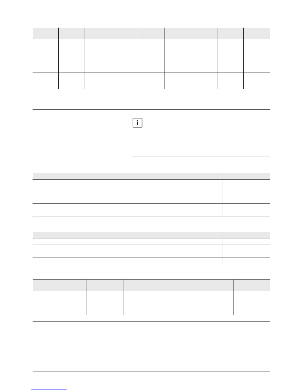
Tab.1 Composition of R-410A fluid
Name
Proportion Number CE Number CAS
Difluoromethane R32 50% 200–839–4 75-10-5
Pentafluoroethane
R125
50% 206-557-8 354-33-6
The Global Warming Potential of R410A gas is 2088.
1 Safety
7613348 - v06 - 10122018 200 ASL HYBRID 11
Page 12

Tab.2 Precautions for use
First aid If inhaled:
Evacuate the subject from the contaminated area and take him into
the open air.
If feeling unwell: call a doctor.
In the event of contact with the skin:
Treat frost injuries like burns. Rinse with copious amounts of tepid
water, do not remove clothing (risk of adhesion to the skin).
If skin burns appear, call a doctor immediately.
In the event of contact with the eyes:
Rinse immediately with water, holding the eyelids well apart (for at
least 15 minutes).
Consult an ophthalmologist immediately.
Fire prevention meas
ures
Appropriate extinguishing agents: All extinguishing agents can be
used.
Inappropriate extinguishing agents: none to our knowledge. In the
event of fire nearby, use the appropriate extinguishing agents.
Specific hazards:
Rise in pressure: in the presence of air, an inflammable mixture
may form under certain temperature and pressure conditions.
Toxic and corrosive vapours may be released by the effect of the
heat.
Special intervention methods: cool the volumes exposed to heat with
water spray.
Protection of the firemen:
Full self-contained breathing apparatus.
Complete body protection.
In the event of acci
dental spillage
Individual precautions:
Avoid contact with the skin and eyes.
Do not intervene without appropriate protective equipment.
Do not inhale the vapours.
Evacuate the hazardous area.
Stop the leakage.
Eradicate all sources of ignition.
Ventilate the spillage area mechanically.
Cleaning / decontamination: allow any residual product to evaporate.
In the event of contact with the eyes: Rinse immediately with water,
holding the eyelids well apart (for at least 15 minutes). Consult an oph
thalmologist immediately.
Handling Technical measures: ventilation
Precautions to be taken:
No smoking.
Prevent the build-up of electrostatic charges.
Work in a well ventilated place.
1 Safety
12 200 ASL HYBRID 7613348 - v06 - 10122018
Page 13

Personal protection Respiratory protection:
If ventilation is insufficient: AX type cartridge mask.
In confined spaces: self-contained breathing apparatus.
Hand protection: protective gloves in leather or nitrile rubber.
Eye protection: safety glasses with side protection.
Skin protection: clothing made principally of cotton
Industrial hygiene: do not drink, eat or smoke at the place of work.
Considerations on dis
posal
Important
Disposal must be done in compliance with prevailing lo
cal and national regulations.
Product waste: consult the manufacturer or the supplier for informa
tion on recovery or recycling.
Soiled packaging: reuse or recycle after decontamination. Destroy in
authorised installations.
Regulation
Regulation (EU) No. 517/2014 of the European Parliament and of the
Council of 16 April 2014 on fluorinated greenhouse gases and re
pealing Regulation (EC) No. 842/2006.
1.4
Liabilities
1.4.1
Manufacturer's liability
Our products are manufactured in compliance with the
requirements of the various Directives applicable. They
are therefore delivered with the marking and any
documents necessary. In the interests of the quality of
our products, we strive constantly to improve them. We
therefore reserve the right to modify the specifications
given in this document.
Our liability as manufacturer may not be invoked in the
following cases:
Failure to abide by the instructions on installing and
maintaining the appliance.
Failure to abide by the instructions on using the
appliance.
Faulty or insufficient maintenance of the appliance.
1.4.2 Installer's liability
The installer is responsible for the installation and initial
commissioning of the appliance. The installer must
observe the following instructions:
Read and follow the instructions given in the manuals
provided with the appliance.
Install the appliance in compliance with prevailing
legislation and standards.
1 Safety
7613348 - v06 - 10122018 200 ASL HYBRID 13
Page 14

Carry out initial commissioning and any checks
necessary.
Explain the installation to the user.
If maintenance is necessary, warn the user of the
obligation to check the appliance and keep it in good
working order.
Give all the instruction manuals to the user.
1.4.3 User's liability
To guarantee optimum operation of the system, you
must abide by the following instructions:
Read and follow the instructions given in the manuals
provided with the appliance.
Call on a qualified professional to carry out installation
and initial commissioning.
Get your installer to explain your installation to you.
Have the required inspections and maintenance
carried out by a qualified installer.
Keep the instruction manuals in good condition close
to the appliance.
1 Safety
14 200 ASL HYBRID 7613348 - v06 - 10122018
Page 15
2 About this manual
2.1 General
This manual is intended for the user of a 200 ASL HYBRIDhybrid system.
2.2
Additional documentation
This manual contains all settings and information on the 200 ASL HYBRID
indoor module, as well as some information on the outdoor unit.
For information on the boiler, refer to the instruction manuals provided with
the boiler.
For additional information on the outdoor unit, refer to the manual provided
with the outdoor unit.
2.3
Symbols used
2.3.1
Symbols used in the manual
This manual uses various danger levels to draw attention to special
instructions. We do this to improve user safety, to prevent problems and to
guarantee correct operation of the appliance.
Danger
Risk of dangerous situations that may result in serious personal
injury.
Danger of electric shock
Risk of electric shock.
Warning
Risk of dangerous situations that may result in minor personal
injury.
Caution
Risk of material damage.
Important
Please note: important information.
See
Reference to other manuals or pages in this manual.
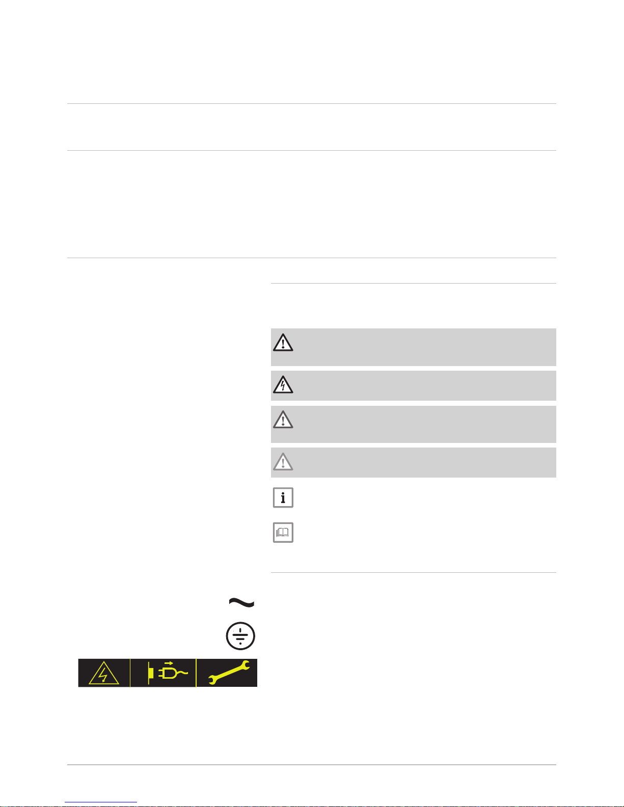
2.3.2 Symbols used on the appliance
1 Alternating current.
2 Protective earthing.
3 Caution: danger of electric shock, live parts. Disconnect the mains
power prior to carrying out any work.
Fig.1 Symbols used on the appliance
1 2
MW-6000066-1
1
2
3
2 About this manual
7613348 - v06 - 10122018 200 ASL HYBRID 15
Page 16
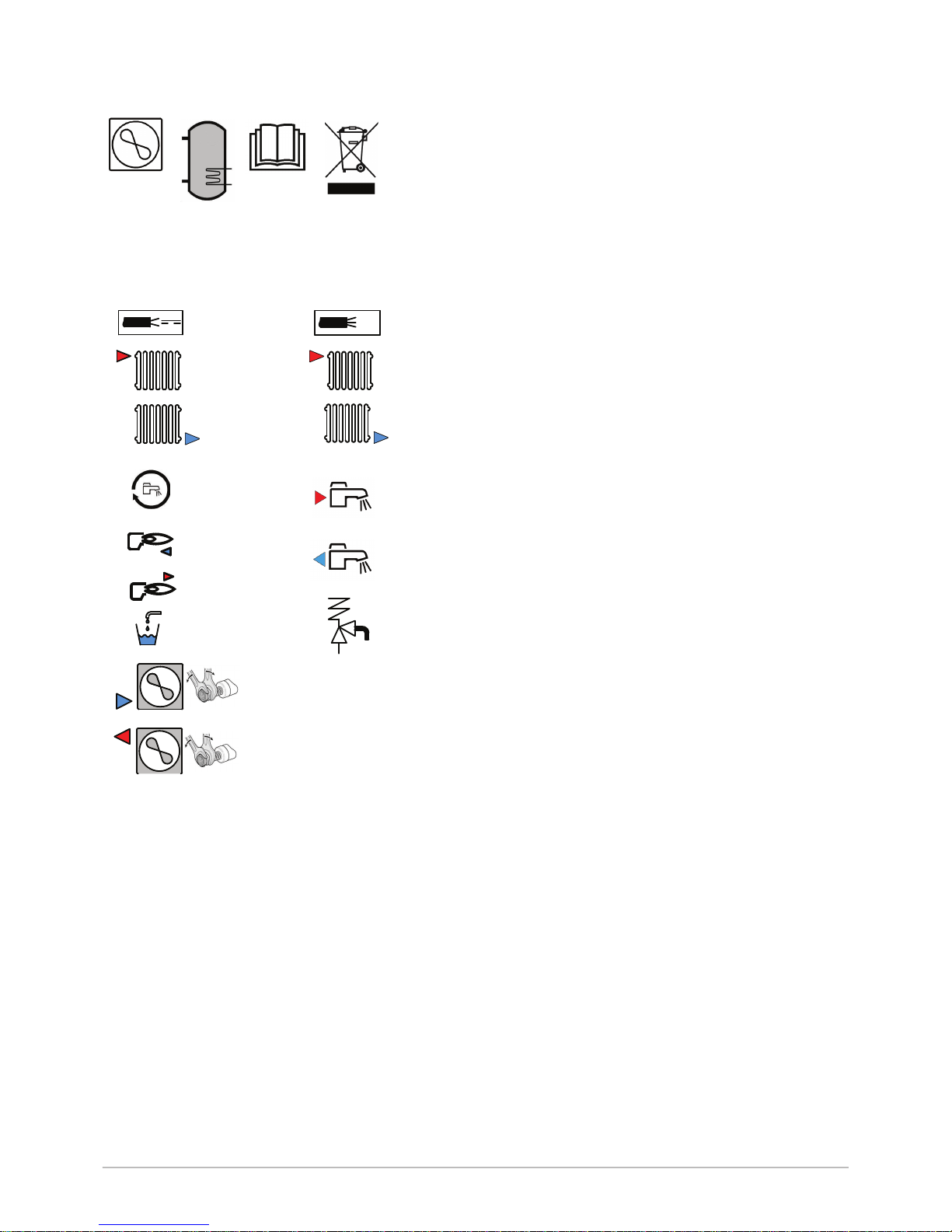
1 Information on the heat pump: Type of refrigerant fluid, maximum
operating pressure, maximum output absorbed by the indoor
module.
2 Information on the domestic hot water tank: Volume, maximum
operating pressure and standby losses of the domestic hot water
tank.
3 Before installing and commissioning the appliance, carefully read
the instruction manuals provided.
4 Dispose of used products through an appropriate recovery and
recycling structure.
1 Sensor cable - low voltage
2 Power cord 230 V
3 Heating circuit flow
4 Circuit B flow
5 Heating circuit return
6 Circuit B return (optional)
7 Connection for recirculation
8 Domestic hot water outlet
9 Return from the indoor module to the boiler
10 Flow from the boiler to the indoor module
11 Domestic cold water inlet
12 Drain valve
13 Safety valve
14
3
/8" refrigerant fluid connection - liquid line
15
5
/8" refrigerant fluid connection - gas line
Fig.2 Symbols used on the data plate
1
2
4
3
MW-6000340-1
Fig.3 Symbols used on the connection
label
G3/4"
A
G1"
A
G1"
B
G1"
B
G1"
G3/4"
G3/4"
5/8
69-82 Nm
3/8
34-42 Nm
Ø13
1
2
4
6
8
10
12
3
5
7
9
11
13
MW-6000285-1
14
15
2 About this manual
16 200 ASL HYBRID 7613348 - v06 - 10122018
Page 17

3 Technical specifications
3.1 Homologations
3.1.1 Directives
This product complies with the requirements of the following European
Directives and Standards:
Pressure Equipment Directive 2014/68/EU
Low Voltage Directive 2014/35/EU
Generic standard: EN 60335-1
Relevant standard: EN 60335-2-40
Electromagnetic Compatibility Directive 2014/30/EU
Generic standards: EN 61000-6-3, EN 61000-6-1
Relevant Standard: EN 55014
This product conforms to the requirements of European Directive
2009/125/EC on the ecodesign of energy-related products.
In addition to the legal requirements and guidelines, the supplementary
guidelines in this manual must also be followed.
Supplements or subsequent regulations and guidelines that are valid at
the time of installation shall apply to all regulations and guidelines
specified in this manual.
3.2 Technical data
3.2.1 Heat pump
Maximum operating pressure: 0.3 MPa (3 bar)
Tab.3 Conditions of use
AWHP 4.5 MR AWHP 6 MR-3 AWHP 8 MR-2 AWHP 11 MR-2
AWHP 11 TR-2
AWHP 16 MR-2
AWHP 16 TR-2
Limit water op
erating temper
atures in heat
ing mode
+18 °C/+55 °C +18 °C/+60 °C +18 °C/+60 °C +18 °C/+60 °C +18 °C/+60 °C
Outdoor air op
erating temper
ature limits in
heating mode
-15° C/+35 °C -15° C/+35 °C -20° C/+35 °C -20° C/+35 °C -20° C/+35 °C
Water operat
ing temperature
limits in cooling
mode
+7°C / +25°C +7°C / +25°C +7°C / +25°C +7°C / +25°C +7°C / +25°C
Outdoor air op
erating temper
ature limits in
cooling mode
+7 °C/ +46 °C +7 °C/ +46 °C +7 °C/ +46 °C +7 °C/ +46 °C +7 °C/ +46 °C
Tab.4 Heating mode: outside air temperature +7 °C, water temperature at the outlet +35 °C. Performances in accordance
with EN 14511-2.
Measure
ment type
Unit AWHP 4.5 MRAWHP 6
MR-3
AWHP 8
MR-2
AWHP 11
MR-2
AWHP 11
TR-2
AWHP 16
MR-2
AWHP 16
TR-2
Heat output kW 4.6 5.82 7.9 11.39 11.39 14.65 14.65
Coefficient
of Perform
ance (COP)
5.11 4.22 4.34 4.65 4.65 4.22 4.22
3 Technical specifications
7613348 - v06 - 10122018 200 ASL HYBRID 17
Page 18

Measure
ment type
Unit AWHP 4.5 MRAWHP 6
MR-3
AWHP 8
MR-2
AWHP 11
MR-2
AWHP 11
TR-2
AWHP 16
MR-2
AWHP 16
TR-2
Absorbed
electrical
power
kWe 0.90 1.38 1.82 2.45 2.45 3.47 3.47
Nominal wa
ter flow rate
(ΔT = 5 K)
m3/hour
0.80 1.00 1.36 1.96 1.96 2.53 2.53
Tab.5 Heating mode: outside air temperature +2 °C, water temperature at the outlet +35 °C. Performances in accordance
with EN 14511-2.
Measure
ment type
Unit AWHP 4.5 MRAWHP 6
MR-3
AWHP 8
MR-2
AWHP 11
MR-2
AWHP 11
TR-2
AWHP 16
MR-2
AWHP 16
TR-2
Heat output kW 3.74 3.74 6.80 10.19 10.19 12.90 12.90
Coefficient
of Perform
ance (COP)
3.97 3.37 3.30 3.19 3.19 3.27 3.27
Absorbed
electrical
power
kWe 0.88 1.11 2.06 3.19 3.19 3.94 3.94
Tab.6 Cooling mode: outside air temperature +35 °C, water temperature at the outlet +18 °C. Performances in accordance
with EN 14511-2.
Measure
ment type
Unit AWHP 4.5 MRAWHP 6
MR-3
AWHP 8
MR-2
AWHP 11
MR-2
AWHP 11
TR-2
AWHP 16
MR-2
AWHP 16
TR-2
Cooling out
put
kW 3.80 4.69 7.90 11.16 11.16 14.46 14.46
Energy effi
ciency ratio
(EER)
4.28 4.09 3.99 4.75 4.75 3.96 3.96
Absorbed
electrical
power
kWe 0.89 1.15 2.00 2.35 2.35 3.65 3.65
Tab.7 Common specifications
Measure
ment type
Unit AWHP 4.5 MRAWHP 6
MR-3
AWHP 8
MR-2
AWHP 11
MR-2
AWHP 11
TR-2
AWHP 16
MR-2
AWHP 16
TR-2
Total dy
namic head
at nominal
flow rate
kPa 65 63 44 25 25 — —
Nominal air
flow rate
m3/h
2650 2700 3300 6000 6000 6000 6000
Power volt
age of the
outdoor unit
V 230 230 230 230 400 230 400
Start-up
amperage
A 5 5 5 5 3 6 3
Maximal
amperage
A 12 13 17 29.5 13 29.5 13
Acoustic
power - In
side
(1)
dB(A) 49 49 49 48 48 48 48
Acoustic
power Outside
(2)
dB(A) 61 65 67 69 69 70 70
Refrigerant
fluid R410A
kg 1.3 1.4 3.2 4.6 4.6 4.6 4.6
3 Technical specifications
18 200 ASL HYBRID 7613348 - v06 - 10122018
Page 19
Measure
ment type
Unit AWHP 4.5 MRAWHP 6
MR-3
AWHP 8
MR-2
AWHP 11
MR-2
AWHP 11
TR-2
AWHP 16
MR-2
AWHP 16
TR-2
R410A re
frigerant
(3)
tCO2e 2.714 2.923 6.680 9.603 9.603 9.603 9.603
Refrigerant
connection
(Liquid Gas)
inch 1/4 - 1/2 1/4 - 1/2 3/8 - 5/8 3/8 - 5/8 3/8 - 5/8 3/8 - 5/8 3/8 - 5/8
Max. precharged
length
m 7 10 10 10 10 10 10
(1) Noise radiated by the envelope - Test run in accordance with the NF EN 12102 standard, temperature conditions: air 7°C, water 55°C
(2) Noise radiated by the envelope - Test run in accordance with the NF EN 12102 standard, temperature conditions: air 7 °C, water 45 °C
for AWHP 4.5 MR only (inner and outer sides).
(3) Quantity of refrigerant calculated in tonnes of CO2 equivalent
Important
The values in tonnes of CO2 equivalent are calculated using the
following formula: quantity (in kg) of refrigerant fluid x GWP /
1000.
The Global-Warming Potential (GWP) of R410A gas is 2088.
3.2.2 Domestic hot water tank
Tab.8 Technical specifications primary circuit (heating water)
Specification Unit Value
Maximum operating temperature
Version with hydraulic back-up
°C 90
Minimum operating temperature °C 7
Maximum operating pressure MPa (bar) 0.3 (3.0)
Exchanger capacity Litres 11.3
Exchange surface m² 1.7
Tab.9 Technical specifications secondary circuit (domestic water)
Specification Unit Value
Maximum operating temperature °C 80
Minimum operating temperature °C 10
Maximum operating pressure MPa (bar) 1.0 (10.0)
Water capacity Litres 177
Tab.10 Common specifications (in accordance with the PR-EN 13203–5 standard)
AWHP 4.5 MR AWHP 6 MR-3 AWHP 8 MR-2 AWHP 11 MR-2 ,
AWHP 11 TR-2
AWHP 16 MR-2 ,
AWHP 16 TR-2
Loading time
(1)
1 hour 21 minutes 1 hour 21 minutes 1 hour 21 minutes 1 hour 33 minutes 1 hour 11 minutes
Coefficient of performance
domestic hot water
(COP
DHW
)
0.75 0.75 0.75 1.07 1.07
(1) Water temperature set point: 57 °C – Outdoor temperature: 7°C – Inside air temperature: 20°C
3 Technical specifications
7613348 - v06 - 10122018 200 ASL HYBRID 19
Page 20

3.2.3 Weight
Tab.11 Indoor module
Indoor module Unit 200 ASL HYBRID 4–8 200 ASL HYBRID 11–16
Weight empty kg 129 131
Total weight with water kg 324 326
Refer to the boiler manual to calculate the total weight of the indoor
module combined with the boiler.
Tab.12 Outdoor unit
Outdoor
unit
Unit AWHP 4.5 MRAWHP 6
MR-3
AWHP 8
MR-2
AWHP 11
MR-2
AWHP 11
TR-2
AWHP 16
MR-2
AWHP 16
TR-2
Weight
empty
kg 54 42 75 118 130 118 130
3.2.4 Combination heaters with medium-temperature heat
pump
Tab.13 Technical parameters for heat pump combination heaters (parameters declared for medium-temperature application)
Product name 200 ASL Hybrid
4.5MR
+ AGC 15
200 ASL Hybrid
6MR-3
+ AGC 25
Air-to-water heat pump Yes Yes
Water-to-water heat pump No No
Brine-to-water heat pump No No
Low-temperature heat pump No No
Equipped with a supplementary heater Yes Yes
Heat pump combination heater Yes Yes
Rated heat output under average conditions
(1)
Prated
kW 8 8
Rated heat output under colder conditions
(1)
Prated
kW 6 6
Rated heat output under warmer conditions
(1)
Prated
kW 4 5
Declared capacity for heating for part load at an indoor
temperature of 20 °C and outdoor temperature
T
j
T
j
= -7°C
Pdh
kW 3.8 3.5
T
j
= +2 °C
Pdh
kW 4.3 4.5
T
j
= +7 °C
Pdh
kW 4.5 4.8
T
j
= +12 °C
Pdh
kW 5.5 5.2
T
j
= bivalent temperature
Pdh
kW 4.3 4.5
T
j
= operation limit temperature
Pdh
kW 3.9 3.6
Bivalent temperature
T
biv
°C 2 2
Degradation co-efficient
(2)
Cdh
— 1.0 1.0
Seasonal space heating energy efficiency under average
conditions
ƞ
s
% 135 132
Seasonal space heating energy efficiency under colder
conditions
ƞ
s
% 122 121
Seasonal space heating energy efficiency under warmer
conditions
ƞ
s
% 172 166
Declared coefficient of performance or primary energy ra
tio for part load at an indoor temperature of 20 °C and
outdoor temperature
T
j
3 Technical specifications
20 200 ASL HYBRID 7613348 - v06 - 10122018
Page 21

Product name 200 ASL Hybrid
4.5MR
+ AGC 15
200 ASL Hybrid
6MR-3
+ AGC 25
T
j
= -7°C
COPd
or
%
1.64 1.86
T
j
= +2 °C
COPd
or
%
3.46 3.40
T
j
= +7 °C
COPd
or
%
4.96 4.52
T
j
= +12 °C
COPd
or
%
7.35 6.70
T
j
= bivalent temperature
COPd
or
%
3.46 3.40
T
j
= operation limit temperature
COPd
or
%
1.84 1.52
Operation limit temperature for air-to-water heat pumps
TOL
°C -10 -10
Heating water operating limit temperature
WTOL
°C 80 80
Electrical power consumption
Off mode
P
OFF
kW 0.009 0.009
Thermostat-off mode
P
TO
kW 0.049 0.049
Stand-by
P
SB
kW 0.016 0.022
Crankcase heater mode
P
CK
kW 0.055 0.055
Supplementary heater
Rated heat output
(1)
Psup
kW 4.0 4.8
Type of energy input Gas Gas
Other specifications
Capacity control Variable Variable
Sound power level, indoors - outdoors
L
WA
dB 49 – 61 48 – 64
Annual energy consumption under average conditions
Q
HE
kWh
GJ
4045
6
4312
7
Annual energy consumption under colder conditions
Q
HE
kWh
GJ
4564
3
4236
3
Annual energy consumption under warmer conditions
Q
HE
kWh
GJ
1299
0
1544
0
Rated air flow rate, outdoors for air-to-water heat
pumps
—
m3/h
2100 2100
Declared load profile L L
Daily electricity consumption
Q
elec
kWh 4.020 4.816
Annual electricity consumption
AEC
kWh 845 968
Water heating energy efficiency
ƞ
wh
% 106.00 106.00
Daily fuel consumption
Q
fuel
kWh 0.000 0.000
Annual fuel consumption
AFC
GJ 0 0
(1) The rated heat output
Prated
is equal to the design load for heating
Pdesignh
, and the rated heat output of a supplementary heater
Psup
is equal to the supplementary capacity for heating
sup(Tj).
(2) If
Cdh
is not determined by measurement then the default degradation coefficient is
Cdh
= 0.9.
3 Technical specifications
7613348 - v06 - 10122018 200 ASL HYBRID 21
Page 22

Tab.14 Technical parameters for heat pump combination heaters (parameters declared for medium-temperature application)
Product name 200 ASL
Hybrid 8MR-2
+ AGC 25
200 ASL
Hybrid 11MR-2
+ AGC 25
200 ASL
Hybrid 16MR-2
+ AGC 25
Air-to-water heat pump Yes Yes Yes
Water-to-water heat pump No No No
Brine-to-water heat pump No No No
Low-temperature heat pump No No No
Equipped with a supplementary heater Yes Yes Yes
Heat pump combination heater Yes Yes Yes
Rated heat output under average conditions
(1)
Prated
kW 11 15 22
Rated heat output under colder conditions
(1)
Prated
kW 9 11 15
Rated heat output under warmer conditions
(1)
Prated
kW 6 8 13
Declared capacity for heating for part load at an
indoor temperature of 20 °C and outdoor temper
ature
T
j
T
j
= -7°C
Pdh
kW 5.6 6.8 9.0
T
j
= +2 °C
Pdh
kW 6.1 8.2 11.8
T
j
= +7 °C
Pdh
kW 6.4 9.0 12.9
T
j
= +12 °C
Pdh
kW 6.5 10.1 15.4
T
j
= bivalent temperature
Pdh
kW 6.1 8.2 11.8
T
j
= operation limit temperature
Pdh
kW 5.6 6.2 8.3
Bivalent temperature
T
biv
°C 2 2 2
Degradation co-efficient
(2)
Cdh
— 1.0 1.0 1.0
Seasonal space heating energy efficiency under
average conditions
ƞ
s
% 135 133 129
Seasonal space heating energy efficiency under
colder conditions
ƞ
s
% 125 122 120
Seasonal space heating energy efficiency under
warmer conditions
ƞ
s
% 169 167 161
Declared coefficient of performance or primary
energy ratio for part load at an indoor tempera
ture of 20 °C and outdoor temperature
T
j
T
j
= -7°C
COPd
or
%
1.95 1.82 1.88
T
j
= +2 °C
COPd
or
%
3.49 3.43 3.33
T
j
= +7 °C
COPd
or
%
4.57 4.54 4.34
T
j
= +12 °C
COPd
or
%
6.33 6.24 5.82
T
j
= bivalent temperature
COPd
or
%
3.49 3.43 3.33
T
j
= operation limit temperature
COPd
or
%
1.63 1.45 1.54
Operation limit temperature for air-to-water
heat pumps
TOL
°C -10 -10 -10
3 Technical specifications
22 200 ASL HYBRID 7613348 - v06 - 10122018
Page 23

Product name 200 ASL
Hybrid 8MR-2
+ AGC 25
200 ASL
Hybrid 11MR-2
+ AGC 25
200 ASL
Hybrid 16MR-2
+ AGC 25
Heating water operating limit temperature
WTOL
°C 80 80 80
Electrical power consumption
Off mode
P
OFF
kW 0.009 0.009 0.009
Thermostat-off mode
P
TO
kW 0.049 0.049 0.049
Stand-by
P
SB
kW 0.022 0.028 0.028
Crankcase heater mode
P
CK
kW 0.055 0.055 0.055
Supplementary heater
Rated heat output
(1)
Psup
kW 5.8 9.0 13.7
Type of energy input Gas Gas Gas
Other specifications
Capacity control Variable Variable Variable
Sound power level, indoors - outdoors
L
WA
dB 48 – 66 47 – 69 47 – 69
Annual energy consumption under average
conditions
Q
HE
kWh
GJ
5859
8
7869
13
11525
20
Annual energy consumption under colder con
ditions
Q
HE
kWh
GJ
6548
6
8009
8
10810
10
Annual energy consumption under warmer
conditions
Q
HE
kWh
GJ
1904
0
2580
0
4120
0
Rated air flow rate, outdoors for air-to-water
heat pumps
—
m3/h
3300 6000 6000
Declared load profile L L L
Daily electricity consumption
Q
elec
kWh 4.816 4.816 4.816
Annual electricity consumption
AEC
kWh 968 968 968
Water heating energy efficiency
ƞ
wh
% 106.00 106.00 106.00
Daily fuel consumption
Q
fuel
kWh 0.000 0.000 0.000
Annual fuel consumption
AFC
GJ 0 0 0
(1) The rated heat output Prated is equal to the design load for heating Pdesignh, and the rated heat output of a supplementary heater
Psup is equal to the supplementary capacity for heating su(Tj).
(2) If
Cdh
is not determined by measurement then the default degradation coefficient is
Cdh
= 0.9.
See
The back cover for contact details.
3.2.5 Circulating pump
Important
The benchmark for the most efficient circulating pumps is EEI ≤
0.20.
The circulating pump in the indoor module is a variable speed pump. It
adapts its speed to the distribution network.
3 Technical specifications
7613348 - v06 - 10122018 200 ASL HYBRID 23
Page 24

1 Available pressure in metres of water column (mWc)
2
Water flow rate in cubic metres per hour (m3/h)
3 Available pressure for 4 to 8 kW outdoor units
4 Available pressure for the 11 and 16 kW outdoor units
Fig.4 Pressure available
MW-2000147-2
0
1
3
4
2
0.5
1.0 1.5 2.0 2.5
1
2
3
4
5
6
7
3 Technical specifications
24 200 ASL HYBRID 7613348 - v06 - 10122018
Page 25

4 Description of the product
4.1 General description
The heat pump comprises:
A 200 ASL HYBRID indoor module, including a domestic hot water tank.
A condensing gas boiler, installed on top of or beside the indoor module.
A reversible outdoor unit for energy production in heating or cooling
mode.
Depending on the parameter settings of the hybrid system, heating and
domestic hot water production are handled by:
The indoor module
The boiler
The indoor module and the outdoor unit are connected by means of
refrigeration and electrical connections.
The system offers the following advantages:
The heating circuit is housed in the insulated volume within the home.
Thanks to the DC inverter system, the heat pump modulates its output
to adapt to the needs of the home.
The temperature of the heating circuit is adjusted according to the
outside temperature.
The tank is protected against corrosion, on the one hand, by a titanium
impressed current anode (Titan Active System) and, on the other, by a
food quality lining vitrified at 850°C.
The heat exchanger in the domestic hot water tank is a coil welded
inside the tank, made of smooth piping. Its external surface, which
comes into contact with drinking water, is enamelled.
The indoor module is insulated by chlorofluorocarbon-free polyurethane
foam, which helps to keep heat losses to a minimum.
4.2 Operating principle
The heat pumps in the 200 ASL HYBRID range extract the heat found in
the air to restore it to the heating and/or domestic hot water circuit via the
refrigerant fluid. The efficiency of a heat pump is expressed in the form of
a coefficient of performance (COP), defined as the ratio between the heat
provided and the power consumed.
The heat pump comprises an evaporator, a compressor, a condenser and
an expansion valve. The indoor module includes the condenser. The other
components (evaporator, compressor and expansion valve) are located in
the outdoor unit.
1. The refrigerant fluid in the circuit is converted from the liquid state to
the gaseous state in the evaporator, making it possible to recover heat
from the air.
2. The compressor increases the fluid pressure, which thus increases
the temperature.
3. In the condenser, the fluid transfers the heat to the heating circuit
while converting to the liquid state.
4. The refrigerant passes through the thermostatic expansion valve and
returns to the initial state at low pressure and low temperature before
returning to the evaporator.
4 Description of the product
7613348 - v06 - 10122018 200 ASL HYBRID 25
Page 26

Fig.5 General operating principle
5
2
1
3
6
4
7
8
MW-6000391-1
1 Evaporator (fin battery in the outdoor unit)
2 Compressor
3 Condenser (plate exchanger in the indoor module)
4 Electronic expansion valve
5 Electrical energy
6 Heating water
7 Energy flow
8 Heat recovered from the environment
4.3 Main components
1
Heating generator control system PCB (EHC-02)
2
Immersion sleeve for the top domestic hot water sensor
3
Flow meter
4
Plate exchanger (condenser part of the heat pump)
5
Immersion sleeve for the bottom domestic hot water sensor
6
3-way valve motor reversing domestic hot water
7
Main circulating pump
8
Safety valve
9
Impressed current anode
10
Automatic air vent
11
Interface PCB for the outdoor unit
12
Magnetic sieve filter
13
Temperature sensor
Fig.6 Main components
MW-2000096-3
13
8
11
9
3
1
2
4
7
12
10
6
5
4 Description of the product
26 200 ASL HYBRID 7613348 - v06 - 10122018
Page 27

1
Heating generator control system PCB (EHC-02)
2
Interface PCB for the outdoor unit
4.4
Description of the control panel
All of the information needed to manage the hybrid heat pump is displayed
on the boiler's control panel.
4.4.1 Description of the keys
1 Temperature setting key: heating, domestic hot water or swimming
pool
2 Operating mode selection key
3 Domestic hot water override key
4 Key to access the parameters reserved for the installer
5 Keys corresponding to the icons shown on the display: the icons
vary depending on the menu
6 Rotary setting button
4.4.2 Description of the display
Functions of the keys
Access to the various menus
Menu scrolling
Parameter scrolling
Help available
Display the curve of the selected parameter
Resetting the timer programs to zero
Selection of the time range in comfort mode
Selection of the time range in reduced mode
Back to the previous level
Back to the previous level without saving the modifications made
Manual reset
Hydraulic back-up
Steady symbol: burner and heating pump controlled by the heat
pump
Flashing symbol: heating pump controlled by the heat pump
Fig.7 Position of the PCBs
MW-5000400-1
1 2
Fig.8 Control panel keys
MW-A000866-5
STD
0 2 4 6 8 10 12 14 16 18 22 2420
b
AUTO
g
1
2
3
4
5
6
w
bar
1
1
2
2
r
c
v
Fig.9
MW-C002696-4
bar
1
2
r
c
STD
(
'
t
p
b
w
r
r
j
M
AUTO
x
c
g
m
Fig.10 Indicator
MW-C002701-3
bar
1
2
r
1
2
c
v
12 14 16 18 22 2420
p
b
w
AUTO
x
c
j
M
g
m
121
2
12
4 Description of the product
7613348 - v06 - 10122018 200 ASL HYBRID 27
Page 28

Status of the compressor
Steady symbol: compressing running
Flashing symbol: compressor off, run request pending
Installation pressure
Pressure indicator: hydraulic pressure sensor connected
Steady symbol: hydraulic pressure sufficient
Flashing symbol: hydraulic pressure insufficient
Hydraulic pressure level
0.9 to 1.1 bar
1.2 to 1.5 bar
1.6 to 1.9 bar
2.0 to 2.3 bar
> 2.4 bar
Cooling mode
Cooling mode on
Summer / Winter Modes
Summer mode on:
heating off,
domestic hot water continues to be produced.
Winter mode on:
heating running,
domestic hot water continues to be produced.
Operating modes
AUTOMATIC mode activated according to the timer program
DAY mode: DAY override activated
Steady symbol: permanent override,
Flashing symbol: temporary override.
NIGHT mode: NIGHT override activated.
Steady symbol: permanent override,
Flashing symbol: temporary override.
HOLIDAYS mode: HOLIDAYS override activated.
Steady symbol: HOLIDAYS mode active,
Flashing symbol: HOLIDAYS mode programmed.
MANUEL mode activated
Domestic hot water override
A vertical bar is displayed at bottom left when a domestic hot water
override is activated.
Fig.11 Indicator
MW-3000171-2
bar
r
1
2
c
1
2
v
16 18 22 2420
p
b
w
AUTO
x
c
j
M
g
m
1
2
16
16
1
2
v
Fig.12
MW-C002708-4
bar
r
1
2
c
1
2
v
0 2 4 6 8 10 12 14 16 18 22 2420
p
b
w
AUTO
x
c
j
M
g
m
12212
AUTO
AUTO
c
bar
Fig.13 Indicator
MW-M002620-3
bar
r
1
2
c
1
2
v
0 2 4 6 8 10 12 14 16 18 22 2420
p
b
w
AUTO
x
c
j
M
g
m
121
2
AUTO
c
w
Fig.14
MW-C002697-5
bar
r
1
2
c
1
2
v
0 2 4 6 8 10 12 14 16 18 22 2420
p
b
w
AUTO
x
c
j
M
g
m
1
2
AUTO
AUTO
c
j
j
j
j
j
j
j
M
p
b
Fig.15 Indicators
MW-C002698-4
bar
1
1
2
2
r
c
v
0 2 4 6 8 10 12 14 16
p
b
w
j
AUTO
x
c
g
m
6810
12
14
16
j
c
AUTO
x
c
g
m
4 Description of the product
28 200 ASL HYBRID 7613348 - v06 - 10122018
Page 29

Steady symbol: permanent override
Flashing symbol: temporary override
Information about the circuits
Domestic hot water production running
Three-way valve connected:
: 3-way valve open
: 3-way valve closed
Pump running
Name of the circuit for which the parameters are displayed
Fig.16
MW-C002707-4
bar
1
1
2
2
r
c
STD
'
t
v
p
b
w
r
r
j
M
AUTO
x
c
g
m
bar
112
2
STD
AUTO
AUTO
AUTO
AUTO
AUTO
AUT
c
Fig.17
MW-C002699-3
bar
1
1
2
2
r
c
v
12 14 16 18 22 2420
p
b
w
AUTO
x
c
j
M
g
m
bar
112
2
12
14
161618
AUTO
c
j
M
r
j
M
4 Description of the product
7613348 - v06 - 10122018 200 ASL HYBRID 29
Page 30

5 Operation
5.1 General
Once the indoor module has been connected to the boiler, the unit is
managed from the boiler control panel. No action need be taken directly
on the indoor module.
The boiler control panel:
displays every item of information on the hybrid heat pump as a whole
(boiler, indoor module, outdoor unit)
is used to make the settings required for the hybrid heat pump to run.
5.2
Use of the control panel
See
Boiler installation and service manual.
5.2.1
Browsing in the menus
Turn the settings button to select:
a menu,
a parameter,
a value.
This action also enables the value for a parameter to be modified once it
has been selected.
Important
To go back to the previous display, press the key.
It is possible to use the and keys instead of the settings
button.
Press the settings button to confirm:
a menu,
a parameter,
a value.
Important
To cancel an input, press the key.
It is possible to use the and keys instead of the settings
button.
Press the return key
as many times as needed to return to the main
display.
5.2.2 Accessing the User level
The information and settings in the User level can be accessed by
everyone.
Press the key to access the User level parameters.
Important
To cancel an input, press the key.
To go back to the previous display, press the key.
Fig.18
r
STD
(
'
t
p
b
AUTO
x
c
r
j
M
g
m
MW-1000411-1
Fig.19
r
STD
(
'
t
p
b
AUTO
x
c
r
j
M
g
m
MW-1000412-1
Fig.20
r
STD
(
'
t
p
b
AUTO
x
c
r
j
M
g
m
MW-1000413-1
Fig.21
r
STD
(
'
t
p
b
AUTO
x
c
r
j
M
g
m
MW-1000416-1
5 Operation
30 200 ASL HYBRID 7613348 - v06 - 10122018
Page 31

5.3 Start-up
1. Switch on the outdoor unit and the indoor module simultaneously.
2. The hybrid heat pump begins its start-up cycle.
If the start-up cycle runs normally, an automatic venting cycle is
initiated. Otherwise, an error message is displayed.
5.4
Installation shutdown
Important
If the heating system is not due to be used for a long period of
time, it is recommended that the boiler be disconnected from the
power supply.
Caution
Some parts of the indoor module remain powered on even when
the boiler's power supply has been cut off. The mains electricity to
the hybrid system must be cut off on the main junction board.
1. Turn the on/off switch to the off position.
2. Cut off the mains electricity to the hybrid system.
3. Shut off the gas supply.
4. Keep the area frost-free.
Warning
In very low temperatures, the installation may freeze if shut down.
It is preferable to keep the installation running at a low
temperature to prevent it from freezing.
5.4.1 Switching off the central heating
See
Boiler manual
5.5
Frost Protection
If the temperature of the heating water in the heat pump falls too much,
the integrated protection device switches itself on. This device functions as
follows:
If the water temperature is lower than 5°C, the circulating pump starts
up.
If the water temperature is lower than 3°C, the back-up starts up.
If the water temperature is higher than 10°C, the back-up shuts down
and the circulating pump continues to run for a short time.
The radiator valves in rooms where there is a risk of frost must be fully
open.
5 Operation
7613348 - v06 - 10122018 200 ASL HYBRID 31
Page 32

6 Settings
6.1 List of parameters
6.1.1 User Level
Menus available at User level:
Access keys Menus
TEMPERATURE
MODE Operating mode
Domestic hot water
#MEASURES
#CHOICE TIME PROG.
#TIME PROGRAM
#SETTING
#ANNUAL PROG
#TIME .DAY
TEMPERATURE menu - User Level
Certain parameters are displayed:
according to certain system configurations,
according to the options, circuits or sensors actually connected.
Tab.15
TEMPERATURE menu ( )
Parameters Description Factory setting Customer setting
DAY TEMP.A Desired room temperature in DAY mode on circuit A.
Can be set from 5 to 30°C.
20°C
NIGHT TEMP.A Desired room temperature in NIGHT mode on circuit A.
Can be set from 5 to 30°C.
16°C
DAY TEMP.B Desired room temperature in DAY mode on circuit B.
Can be set from 5 to 30°C.
20°C
NIGHT TEMP.B Desired room temperature in NIGHT mode on circuit B.
Can be set from 5 to 30°C.
16°C
DAY TEMP.C Desired room temperature in DAY mode on circuit C.
Can be set from 5 to 30°C.
20°C
NIGHT TEMP.C Desired room temperature in NIGHT mode on circuit C.
Can be set from 5 to 30°C.
16°C
WATER TEMP. Desired domestic hot water temperature in the domestic hot
water circuit.
Can be set from 40 to 65°C.
55°C
DHW A TEMP. Desired temperature for the domestic hot water in the do
mestic hot water tank connected to circuit A.
Can be set from 10 to 80°C.
55°C
DHW B TEMP. Desired temperature for the domestic hot water in the do
mestic hot water tank connected to circuit B.
Can be set from 10 to 80°C.
55°C
DHW TEMP.C Desired temperature for the domestic hot water in the do
mestic hot water tank connected to circuit C.
Can be set from 10 to 80°C.
55°C
TEMP.TANK AUX Desired domestic hot water temperature in the auxiliary cir
cuit.
Can be set from 10 to 80°C.
55°C
SWIMMING P.T.B Desired temperature for the swimming pool connected to cir
cuit B.
Can be set from 5 to 39°C.
20°C
6 Settings
32 200 ASL HYBRID 7613348 - v06 - 10122018
Page 33

Parameters Description Factory setting Customer setting
SWIMMING P.T.C Desired temperature for the swimming pool connected to cir
cuit C.
Can be set from 5 to 39°C.
20°C
WATER T.NIGHT Desired domestic hot water temperature in the domestic hot
water circuit.
Can be set from 40 to 65°C.
10°C
WATER T.NIGHT.A Temperature set point in NIGHT mode for a second domestic
hot water tank connected to circuit A.
Can be set from 10 to 80°C.
10°C
WATER T.NIGHT.B Temperature set point in NIGHT mode for a second domestic
hot water tank connected to circuit B.
Can be set from 10 to 80°C.
10°C
WATER T.NIGHT.C Temperature set point in NIGHT mode for a second domestic
hot water tank connected to circuit C.
Can be set from 10 to 80°C.
10°C
WATER T.NIGHTAUX Temperature set point in NIGHT mode for a second domestic
hot water tank connected to the auxiliary circuit.
Can be set from 10 to 80°C.
10°C
MODE menu - User Level
Certain parameters are displayed:
according to certain system configurations,
according to the options, circuits or sensors actually connected.
Tab.16 Menu MODE
Parameters Description Factory setting Customer setting
FORCE AUTO An operating mode override is activated on the remote con
trol (optional).
To force every circuit in AUTOMATIC mode, select the value:
ON.
AUTOMATIC The temperatures switch automatically from DAY mode to
NIGHT mode according to the setting on the #TIME
PROGRAM menu.
DAY DAY mode is forced:
DAY -> : until the set time
DAY 7/7 : at all times 24/7
Current time + 1
hour
NIGHT NIGHT mode is forced:
NIGHT -> : until the set time
NIGHT 7/7 : at all times 24/7
Current time + 1
hour
HOLIDAYS Frost protection mode is active:
DAYS ANTIFREEZ : number of days' holiday
STOP HEAT : heating shut-down date
RE-START : heating restart date
The start and end days and the number of days are calcula
ted in relation to each other.
Current date + 1
hour
SUMMER SUMMER mode is forced:
the heating is shut down
domestic hot water continues to be produced
COLD COOLING mode is forced without taking into account the
outside temperature or the SUM/WIN parameter.
MANUEL The appliance operates according to the set point settings.
All of the pumps operate.
Possibility of setting the set point by simply turning the but
ton.
6 Settings
7613348 - v06 - 10122018 200 ASL HYBRID 33
Page 34

Domestic Hot Water menu - User Level
Tab.17
Domestic Hot Water menu ( )
Parameters Description Factory setting
AUTOMATIC Domestic hot water production is determined by the setting in the #TIME
PROGRAM menu.
COMFORT 7/7 Domestic hot water production is forced at all times: seven days a week. Current time + 1
hour
COMFORT -> Domestic hot water production is forced until the set time: Current time + 1
hour
#MEASURES menu - User Level
Certain parameters are displayed:
according to certain system configurations,
according to the options, circuits or sensors actually connected.
Tab.18 Menu #MEASURES
Parameters Description Unit
OUTSIDE TEMP. Outside temperature °C
ROOMTEMP.A Room temperature on circuit A °C
ROOMTEMP.B Room temperature on circuit B °C
ROOMTEMP.C Room temperature on circuit C °C
BOILER TEMP. Water temperature in the boiler °C
PRESSURE Water pressure in the system °C
OIL PRESSURE Oil circuit pressure bar (MPa)
DHW TEMP. Water temperature in the domestic hot water tank °C
STO.TANK.T.AUX Water temperature in the second domestic hot water tank connected to the Aux
iliary circuit
°C
S.TAN.T.AUX.BO Water temperature in the bottom of the domestic hot water tank °C
S.TAN.T.AUX.BO Water temperature in the bottom of the second domestic hot water tank connec
ted to the Auxiliary circuit
°C
TEMPERATURE DCW Domestic cold water temperature °C
SWIMMING P.T.B Water temperature of the swimming pool on circuit B °C
SWIMMING P.T.C Water temperature of the swimming pool on circuit C °C
OUTLET TEMP.B Water flow temperature in circuit B °C
OUTLET TEMP.C Water flow temperature in circuit C °C
TEMP.SYSTEM Water flow temperature in the system if multi-generator °C
T.DHW BOTTOM Water temperature in the bottom of the domestic hot water tank °C
TEMP.TANK AUX Water temperature in the second domestic hot water tank connected to the Aux
iliary circuit
°C
TEMP.DHW A Water temperature in the domestic hot water tank connected to circuit A °C
DHW B TEMP. Water temperature in the domestic hot water tank connected to circuit B °C
DHW TEMP.C Water temperature in the domestic hot water tank connected to circuit C °C
TEMP.EXCHANGE Temperature measurement on the heat exchanger sensor °C
BACK TEMP Temperature of the boiler return water °C
FAN SPEED Fan rotation speed rpm
POWER Instantaneous output relative to the boiler:
0%: burner off or operating at minimum output
100%: operating at maximum output
%
HEAT CONS. Energy consumed by the boiler in heating mode kWh
DHW CONS. Energy consumed by the boiler in domestic hot water mode
CURRENT Ionisation current µA
6 Settings
34 200 ASL HYBRID 7613348 - v06 - 10122018
Page 35

Parameters Description Unit
NB IMPULS. Number of burner start-ups (cannot be reinitialised).
The meter is incremented by 8 every 8 start-ups.
RUNTIME Number of hours' burner operation (cannot be reinitialised).
The meter is incremented by 2 every 2 hours.
h
IN 0-10V Voltage on the input 0-10V V
CTRL Software control number
#CHOICE TIME PROG. menu - User Level
Timer program P1 cannot be modified.
Factory setting P1: Monday to Sunday from 6:00 to 22:00.
Tab.19 Menu #CHOICE TIME PROG.
Parameters Description
Adjustment
range
CURRENT PROG.A Choice of the timer program applied to circuit A P1, P2, P3, P4
CURRENT PROG.B Choice of the timer program applied to circuit B P1, P2, P3, P4
CURRENT PROG.C Choice of the timer program applied to circuit C P1, P2, P3, P4
#TIME PROGRAM menu - User Level
Tab.20 Menu #TIME PROGRAM
Parameters Comfort period / Loading enabled
TIME PROG.A PROG P2 A
PROG P3 A
PROG P4 A
TIME PROG.B PROG P2 B
PROG P3 B
PROG P4 B
TIME PROG.C PROG P2 C
PROG P3 C
PROG P4 C
TIME PROG.DHW Prog DHW
TIME PROG.AUX Prog AUX
TIME PROG.BUFFER
TANK
Prog BUFF.TANK
Tab.21 Timer programs on the heating circuits
Parameters Comfort period / Loading enabled Factory setting Customer setting
PROG P2 A
PROG P2 B
PROG P2 C
Monday:
Tuesday:
Wednesday:
Thursday:
Friday:
Saturday:
Sunday:
4:00-21:00
4:00-21:00
4:00-21:00
4:00-21:00
4:00-21:00
4:00-21:00
4:00-21:00
PROG P3 A
PROG P3 B
PROG P3 C
Monday:
Tuesday:
Wednesday:
Thursday:
Friday:
Saturday:
Sunday:
5:00-8:00 / 16:00-22:00
5:00-8:00 / 16:00-22:00
5:00-8:00 / 16:00-22:00
5:00-8:00 / 16:00-22:00
5:00-8:00 / 16:00-22:00
7:00-23:00
7:00-23:00
6 Settings
7613348 - v06 - 10122018 200 ASL HYBRID 35
Page 36

Parameters Comfort period / Loading enabled Factory setting Customer setting
PROG P4 A
PROG P4 B
PROG P4 C
Monday:
Tuesday:
Wednesday:
Thursday:
Friday:
Saturday:
Sunday:
6:00-8:00 / 11:00-13:30 / 16:00-22:00
6:00-8:00 / 11:00-13:30 / 16:00-22:00
6:00-8:00 / 11:00-13:30 / 16:00-22:00
6:00-8:00 / 11:00-13:30 / 16:00-22:00
6:00-8:00 / 11:00-13:30 / 16:00-22:00
6:00-23:00
6:00-23:00
Prog DHW Monday:
Tuesday:
Wednesday:
Thursday:
Friday:
Saturday:
Sunday:
6:00-22:00
6:00-22:00
6:00-22:00
6:00-22:00
6:00-22:00
6:00-22:00
6:00-22:00
Prog AUX Monday:
Tuesday:
Wednesday:
Thursday:
Friday:
Saturday:
Sunday:
6:00-22:00
6:00-22:00
6:00-22:00
6:00-22:00
6:00-22:00
6:00-22:00
6:00-22:00
Prog BUFF.TANK Monday:
Tuesday:
Wednesday:
Thursday:
Friday:
Saturday:
Sunday:
6:00-22:00
6:00-22:00
6:00-22:00
6:00-22:00
6:00-22:00
6:00-22:00
6:00-22:00
#SETTING menu - User Level
Certain parameters are displayed:
according to certain system configurations,
according to the options, circuits or sensors actually connected.
Tab.22 Menu #SETTING
Parameters Description Factory setting Customer setting
CONTRAST DISP. Adjusting the display contrast
BACK LIGHT COMFORT : the screen is illuminated continuously in day
time periods
ECO : the screen is illuminated for 2 minutes whenever a
key on the control panel is pressed
ECO
PERMUT Used to establish the pilot boiler
AUTO : the pilot boiler automatically switches every 7 days
Can be set from 1 to 10: number of the boiler chosen as
the master boiler
AUTO
SUM/WIN BAND Outside temperature above which the heating will be shut
down:
OFF : The heating is never shut down automatically.
Can be set from 15 to 30°C.
The heating pumps are shut down.
The burner only starts for domestic hot water needs.
The symbol is displayed.
22°C
CALIBR.OUT Outside sensor calibration
Is used to correct the outside temperature information.
Outside tempera
ture
OFFSET ROOM A Room temperature offset on circuit A.
Make this setting 2 hours after switching on, when the room
temperature has stabilised.
Can be set from -5 to +5 °C.
0
6 Settings
36 200 ASL HYBRID 7613348 - v06 - 10122018
Page 37

Parameters Description Factory setting Customer setting
ANTIFR.ROOM A Room temperature at which frost protection on circuit A is ac
tivated.
Can be set from 0.5 to 20 °C.
6°C
CALIBR.ROOM A Calibration of the room temperature sensor on circuit A.
Make this setting 2 hours after switching on, when the room
temperature has stabilised.
Room tempera
ture on circuit A
OFFSET ROOM B Room temperature offset on circuit B.
Is used to set a room temperature offset.
Make this setting 2 hours after switching on, when the room
temperature has stabilised.
Can be set from -5 to +5 °C.
0
ANTIFR.ROOM B Room temperature at which frost protection on circuit B is ac
tivated.
Can be set from 0.5 to 20 °C.
6°C
CALIBR.ROOM B Calibration of the room temperature sensor on circuit B.
Make this setting 2 hours after switching on, when the room
temperature has stabilised.
Room tempera
ture on circuit B
OFFSET ROOM C Room temperature offset on circuit C.
Is used to set a room temperature offset.
Make this setting 2 hours after switching on, when the room
temperature has stabilised.
Can be set from -5 to +5 °C.
0
ANTIFR.ROOM C Room temperature at which frost protection on circuit C is
activated.
Can be set from 0.5 to 20 °C.
6°C
CALIBR.ROOM C Calibration of the room temperature sensor on circuit C.
Make this setting 2 hours after switching on, when the room
temperature has stabilised.
Room tempera
ture on circuit C
#ANNUAL PROG menu - User Level
Tab.23 Menu #ANNUAL PROG
Parameters Description
STOP N 1 BEG.DATE N 01
BEG.MONTH N 01
END DATE N 01
END DATE N 01
STOP N 2 BEG.DATE N 02
BEG.MONTH N 02
END DATE N 02
END MONTH N 02
STOP N 3 BEG.DATE N 03
BEG.MONTH N 03
END DATE N 03
END MONTH N 03
STOP N 4 BEG.DATE N 04
BEG.MONTH N 04
END DATE N 04
END MONTH N 04
STOP N 5 BEG.DATE N 05
BEG.MONTH N 05
END DATE N 05
END MONTH N 05
STOP N 6 BEG.DATE N 06
BEG.MONTH N 06
END DATE N 06
END MONTH N 06
6 Settings
7613348 - v06 - 10122018 200 ASL HYBRID 37
Page 38

Parameters Description
STOP N 7 BEG.DATE N 07
BEG.MONTH N 07
END DATE N 07
END MONTH N 07
STOP N 8 BEG.DATE N 08
BEG.MONTH N 08
END DATE N 08
END MONTH N 08
STOP N 9 BEG.DATE N 09
BEG.MONTH N 09
END DATE N 09
END MONTH N 09
STOP N 10 BEG.DATE N 10
BEG.MONTH N 10
END DATE N 10
END MONTH N 10
For each programmable heating shut-down period, it is possible to select
one or more circuits to be shut down according to the following list:
NO : no circuits selected
A : circuit A selected
B : circuit B selected
C : circuit C selected
A+B : circuits A and B selected
A+C : circuits A and C selected
B+C : circuits B and C selected
A+B+C : circuits A, B and C selected
E : circuit E selected
A+E : circuits A and E selected
B+E : circuits B and E selected
A+B+E : circuits A, B and E selected
C+E : circuits C and E selected
A+C+E : circuits A, C and E selected
B+C+E : circuits B, C and E selected
ALL : all circuits are selected
Tab.24 STOP N 1
Parameters Description Factory setting Customer setting
BEG.DATE N 01
BEG.MONTH N 01
END DATE N 01
END DATE N 01
Shut-down start date: can be set from 1 to 31
Shut-down start month: can be set from 1 to 12
Shut-down end date: can be set from 1 to 31
Shut-down end month: can be set from 1 to 12
01
01
01
01
Tab.25 STOP N 2
Parameters Description Factory setting Customer setting
BEG.DATE N 02
BEG.MONTH N 02
END DATE N 02
END MONTH N 02
Shut-down start date: can be set from 1 to 31
Shut-down start month: can be set from 1 to 12
Shut-down end date: can be set from 1 to 31
Shut-down end month: can be set from 1 to 12
01
01
01
01
Tab.26 STOP N 3
Parameters Description Factory setting Customer setting
BEG.DATE N 03
BEG.MONTH N 03
END DATE N 03
END MONTH N 03
Shut-down start date: can be set from 1 to 31
Shut-down start month: can be set from 1 to 12
Shut-down end date: can be set from 1 to 31
Shut-down end month: can be set from 1 to 12
01
01
01
01
6 Settings
38 200 ASL HYBRID 7613348 - v06 - 10122018
Page 39

Tab.27 STOP N 4
Parameters Description Factory setting Customer setting
BEG.DATE N 04
BEG.MONTH N 04
END DATE N 04
END MONTH N 04
Shut-down start date: can be set from 1 to 31
Shut-down start month: can be set from 1 to 12
Shut-down end date: can be set from 1 to 31
Shut-down end month: can be set from 1 to 12
01
01
01
01
Tab.28 STOP N 5
Parameters Description Factory setting Customer setting
BEG.DATE N 05
BEG.MONTH N 05
END DATE N 05
END MONTH N 05
Shut-down start date: can be set from 1 to 31
Shut-down start month: can be set from 1 to 12
Shut-down end date: can be set from 1 to 31
Shut-down end month: can be set from 1 to 12
01
01
01
01
Tab.29 STOP N 6
Parameters Description Factory setting Customer setting
BEG.DATE N 06
BEG.MONTH N 06
END DATE N 06
END MONTH N 06
Shut-down start date: can be set from 1 to 31
Shut-down start month: can be set from 1 to 12
Shut-down end date: can be set from 1 to 31
Shut-down end month: can be set from 1 to 12
01
01
01
01
Tab.30 STOP N 7
Parameters Description Factory setting Customer setting
BEG.DATE N 07
BEG.MONTH N 07
END DATE N 07
END MONTH N 07
Shut-down start date: can be set from 1 to 31
Shut-down start month: can be set from 1 to 12
Shut-down end date: can be set from 1 to 31
Shut-down end month: can be set from 1 to 12
01
01
01
01
Tab.31 STOP N 8
Parameters Description Factory setting Customer setting
BEG.DATE N 08
BEG.MONTH N 08
END DATE N 08
END MONTH N 08
Shut-down start date: can be set from 1 to 31
Shut-down start month: can be set from 1 to 12
Shut-down end date: can be set from 1 to 31
Shut-down end month: can be set from 1 to 12
01
01
01
01
Tab.32 STOP N 9
Parameters Description Factory setting Customer setting
BEG.DATE N 09
BEG.MONTH N 09
END DATE N 09
END MONTH N 09
Shut-down start date: can be set from 1 to 31
Shut-down start month: can be set from 1 to 12
Shut-down end date: can be set from 1 to 31
Shut-down end month: can be set from 1 to 12
01
01
01
01
Tab.33 STOP N 10
Parameters Description Factory setting Customer setting
BEG.DATE N 10
BEG.MONTH N 10
END DATE N 10
END MONTH N 10
Shut-down start date: can be set from 1 to 31
Shut-down start month: can be set from 1 to 12
Shut-down end date: can be set from 1 to 31
Shut-down end month: can be set from 1 to 12
01
01
01
01
6 Settings
7613348 - v06 - 10122018 200 ASL HYBRID 39
Page 40

#TIME .DAY menu - User Level
Tab.34 Menu #TIME .DAY
Parameters Description Factory setting Customer setting
HOURS Hours.
Can be set from 0 to 23.
MINUTE Minutes.
Can be set from 0 to 59.
DAY Day of the week.
Can be set from Monday to Sunday.
DATE The day's date.
Can be set from 1 to 31.
MONTH Month.
Can be set from January to December.
YEAR Year.
Can be set from 2014 to 2099.
SUM.TIME AUTO :
Automatic switch to summer time on the last Sunday in
March
Automatic switch to winter time on the last Sunday in
October
MANU :
For countries where the time change is done on other
dates or is not in use
AUTO
#HYBRID Menu - User Level
Tab.35 Menu #HYBRID
Parameter Description Factory setting Customer setting
HYBRID ENABLED NO : The hybrid control system is not activated.
COST : The hybrid control system optimises run
ning according to energy costs.
PRIM.EN : The hybrid control system optimises
running according to primary energy consump
tion.
CO2 : The hybrid control system optimises run
ning according to the quantity of CO2 emitted.
NO
COST HIGH TARIFF
(1)
Cost of peak time electricity. € 0.13
COST LOW TARIFF
(1)
Cost of off-peak electricity. The tariff is only fac
tored in if the E.BL parameter is set to PEAK/OFFPEAK and the contact BL input is closed.
€ 0.09
COST GAS/OIL
(1)
Cost of fossil energy (oil or gas) (Price of fossil en
ergy (oil or gas) per litre or m
3
)
€ 0.90
BOIL.EFFICIENCY
(1)
Efficiency of the boiler connected as back-up. 1
COEF.CO2.E.HEAT
(2)
Coefficient of carbon gas emissions from the heat
pump in heating mode
0.18
COEF.CO2.E.DHW
(2)
Coefficient of carbon gas emissions from the heat
pump in domestic hot water mode
0.04
COEF.CO2.GAS.OIL
(2)
Coefficient of carbon gas emissions from the gas /
oil boiler.
0.23
(1) The parameter is only displayed if HYBRID ENABLED is set to COST
(2) The parameter is only displayed if the HYBRID ENABLED parameter is set to CO2
6.2
User settings
Lists of user settings and parameters available in the user manual:
Setting the Set Point Temperatures
6 Settings
40 200 ASL HYBRID 7613348 - v06 - 10122018
Page 41

Selecting the Operating Mode
Forcing domestic hot water production
Selecting a Timer Program
Customising a timer program
Calibrating the sensors
Setting the contrast and brightness of the display
Setting the Time and Date
6.2.1 Setting the Set Point Temperatures
1. Go to the set point temperature settings by pressing the key.
2. Select the desired parameter by turning the settings button.
3. Confirm the selection by pressing the settings button.
Important
Go back to the previous display by pressing the key.
4. Modify the value of the parameter by turning the settings button.
5. Confirm the modification by pressing the settings button.
Important
Cancel the input by pressing the key.
6. Go back to the main display by pressing the key.
6.2.2
Selecting the Operating Mode
1. Go to the operating mode by pressing the MODE key.
2. Select the desired parameter by turning the settings button.
3. Confirm the selection by pressing the settings button.
Important
Go back to the previous display by pressing the key.
4. Modify the value of the parameter by turning the settings button.
5. Confirm the modification by pressing the settings button.
Important
Cancel the input by pressing the key.
6. Go back to the main display by pressing the key.
6.2.3 Forcing domestic hot water production
1. Go to the domestic hot water production menu by pressing the
key.
2. Select the desired parameter by turning the settings button.
3. Confirm the selection by pressing the settings button.
Important
Go back to the previous display by pressing the key.
4. Modify the value of the parameter by turning the settings button.
5. Confirm the modification by pressing the settings button.
Important
Cancel the input by pressing the key.
6. Go back to the main display by pressing the key.
Fig.22
Accessing the set point temperature
settings
MODE
MW-C002266-A
Fig.23 Selecting the operating mode
MODE
MW-C002267-1
Fig.24 Forcing domestic hot water
production
MODE
MW-C002268-A
6 Settings
7613348 - v06 - 10122018 200 ASL HYBRID 41
Page 42

6.2.4 Selecting a timer programme
1. Go to the User level by pressing the key.
2. Select the #CHOICE TIME PROG. menu by turning the settings
button.
3. Confirm the selection by pressing the settings button.
Important
Go back to the previous display by pressing the key.
4. Select the circuit for which the timer program is to be activated by
turning the settings button.
5. Confirm the selection by pressing the settings button.
6. Select the predefined timer range by turning the settings button.
7. Confirm the desired time range by pressing the settings button.
Important
Cancel by pressing the key.
8. Go back to the main display by pressing the key twice.
The new time range is highlighted at the top of the display.
6.2.5 Customising a timer program
The #TIME PROGRAM menu is used to customise a timer program and to
choose new time ranges.
1. Go to the User level by pressing the key.
2. Select the #TIME PROGRAM menu by turning the settings button.
3. Confirm the selection by pressing the settings button.
4. Select the circuit for which the timer program is to be set by turning
the settings button.
5. Confirm the selection by pressing the settings button.
Important
Go back to the previous display by pressing the key.
6. Select the timer program for the circuit selected by turning the settings
button.
Important
Cancel the input by pressing the key.
7. Confirm the selection by pressing the settings button.
8. Choose a day by turning the settings button to select or deselect a
day.
Fig.25
Selecting a day
bar
1
1
2
2
r
c
STD
(
'
t
v
0 2 4 6 8 10 12 14 16 18 22 2420
p
b
AUTO
x
c
r
j
L
g
m
PROG P2 C
Mo Tu We Th Fr Sa Su
"Display of the timeprogram.
To continuepush on the button"
a
C002228-B-04
6 Settings
42 200 ASL HYBRID 7613348 - v06 - 10122018
Page 43

9. Select or deselect a day by pressing the settings button once or twice.
The symbol is displayed for selection.
The symbol is displayed for deselection.
10. Confirm one or more days by pressing the settings button.
The day(s) selected are highlighted.
Important
It is possible to select several days:
Choose another day by placing the cursor over the
desired day by turning the settings button to the left.
Select the day when the cursor is over the day desired by
pressing the settings button.
11. Choose a timer range start time by turning the settings button to the
left to situate the cursor.
Important
The cursor flashes.
Setting can be done in 30-minute steps.
12. Select a time range by turning the settings button to the right when the
symbol is displayed.
13. Deselect a timer range by turning the settings button to the right when
the symbol
is displayed.
14. Confirm the start or end time of the time range by pressing the
settings button.
The time range selected is highlighted.
15. Repeat the foregoing steps to define the time ranges for the other
days.
16. Go back to the main display by pressing the key twice.
The new time range is highlighted at the top of the display.
6.2.6 Calibrating the sensors
1. Go to the User level by pressing the key.
2. Select the #SETTING menu by turning the settings button.
3. Confirm the selection by pressing the settings button.
Important
Go back to the previous display by pressing the key.
4. Select the CALIBR.OUT parameter by turning the settings button.
5. Modify the value of the parameter by turning the settings button.
6. Confirm the modification by pressing the settings button.
Important
Cancel the input by pressing the key.
7. Go back to the main display by pressing the key.
Fig.26
Selecting/deselecting a day
bar
1
1
2
2
r
c
STD
(
'
t
v
0 2 4 6 8 10 12 14 16 18 22 2420
p
b
AUTO
x
c
r
j
L
g
m
PROG P2 C
Mo Tu
We Th Fr Sa Su
"Select the days to
program"
a
C002229-C-04
Fig.27 Selecting/deselecting the timer
range
bar
1
1
2
2
r
c
STD
(
'
t
v
0 2 4 6 8 10 12 14 16 18 22 2420
p
b
AUTO
x
c
r
j
L
g
m
PROG P2 C
Mo Tu
We Th Fr Sa Su
Set the time program.
a
C002230-E-04
06:00
06:00
Fig.28 Repeating selection/deselection
bar
1
1
2
2
r
c
STD
(
'
t
v
0 2 4 6 8 10 12 14 16 18 22 2420
p
b
AUTO
x
c
r
j
L
g
m
PROG P2 C
Mo Tu
We Th Fr Sa Su
"Select the days to
program"
a
C002229-C-04
6 Settings
7613348 - v06 - 10122018 200 ASL HYBRID 43
Page 44

6.2.7 Setting the contrast and brightness of the display
1. Go to the User level by pressing the key.
2. Select the #SETTING menu by turning the settings button.
3. Confirm the selection by pressing the settings button.
Important
Go back to the previous display by pressing the key.
4.
Select the desired parameter: CONTRAST DISP. or BACK LIGHT by
turning the settings button.
5. Confirm the selection by pressing the settings button.
6. Modify contrast or brightness of the display by turning the settings
button.
7. Confirm the modification by pressing the settings button.
Important
Cancel the input by pressing the key.
8. Go back to the main display by pressing the key.
6.2.8 Setting the time and date
1. Go to the User level by pressing the key.
2. Select the #TIME .DAY parameter by turning the settings button.
3. Confirm the selection by pressing the settings button.
Important
Go back to the previous display by pressing the key.
4. Select the parameter to be modified by turning the settings button.
5. Confirm the selection by pressing the settings button.
6. Modify the parameter by turning the settings button.
7. Confirm the modification by pressing the settings button.
Important
Cancel the input by pressing the key.
8. Go back to the main display by pressing the key.
6 Settings
44 200 ASL HYBRID 7613348 - v06 - 10122018
Page 45

7 Maintenance
7.1 General
Maintenance operations are important for the following reasons:
To guarantee optimum performance.
To extend the life of the equipment.
To provide an installation which offers the user optimum comfort over
time.
Caution
Maintenance work must be carried out by a qualified professional.
Danger
Before any work, switch off the mains electricity to the heat pump
and the hydraulic or electrical back-up if connected.
Caution
Before working on the refrigeration circuit, switch off the appliance
and wait a few minutes. Certain items of equipment such as the
compressor and the pipes can reach temperatures in excess of
100°C and high pressures, which may cause serious injuries.
Caution
Do not drain the installation, except in cases of absolute
necessity. E.g.: several months' absence with the risk of
temperatures in the building falling below freezing.
7.1.1 Troubleshooting
Caution
All work on the refrigeration circuit must be done by a qualified
professional, according to prevailing codes of practice and safety
in the profession (recovery of the refrigerant, brazing under
nitrogen). All brazing work must be done by qualified welders.
Caution
This appliance is fitted with pressurised equipment, including the
refrigeration pipes.
Caution
Use only original parts to replace a defective refrigeration
component.
Caution
Use only dehydrated nitrogen for detecting leaks or for
pressurised tests.
Caution
The safety devices may only be set, corrected or replaced by a
qualified professional. Any modification must be tested and
reported in the commissioning protocol.
7.2
Standard inspection and maintenance operations
An annual inspection with tightness check is obligatory. Schedule a
service by a qualified professional at a cold time of the year to check the
following points:
1. Operation of the installation.
2. Thermal output, by measuring the difference in temperature between
heating flow and return.
3. The setting for the safety thermostats.
7 Maintenance
7613348 - v06 - 10122018 200 ASL HYBRID 45
Page 46

7.3 Cleaning the casing
1. Clean the outside of the appliance using a damp cloth and a mild
detergent.
7 Maintenance
46 200 ASL HYBRID 7613348 - v06 - 10122018
Page 47

8 Troubleshooting
8.1 Error codes
8.1.1 Error messages
If an error occurs, the control panel displays an error message and the
corresponding code.
1. Make a note of the code displayed.
The code is important for the correct and rapid diagnosis of the type
of error and for any technical assistance that may be needed.
2. Switch the generator off and switch it back on.
The generator starts up again automatically when the reason for the
disruption has been eradicated.
3. If the code is displayed again, follow the instructions shown on the
control panel to resolve the problem.
4. Contact the professional who handles maintenance of the appliance.
8.1.2 Faults
In the event of operational failure, the control panel flashes and displays
an error message and a corresponding code.
1. Make a note of the code displayed.
The code is important for the correct and rapid diagnosis of the type
of error and for any technical assistance that may be needed.
2. Press the key to clear the fault.
3. If the code is displayed again, switch off the appliance and then switch
it back on.
4. Press the key to proceed with resolving the problem.
5. If the code is displayed again, follow the instructions shown on the
control panel to resolve the problem.
6. Contact the professional who handles maintenance of the appliance.
8.2
Error memory
8.2.1 Message History
The #MESSAGE HISTORIC menu is used to consult the last 10 messages
displayed by the control panel.
Fig.29
bar
1
1
2
2
r
c
STD
(
t
v
0 2 4 6 8 10 12 14 16 18 22 2420
p
b
AUTO
x
c
r
j
M
g
m
SUNDAY 11:45
TEMP. : 68°
PCU. COM. FAIL. D27
C002604-B-04
Fig.30
bar
1
1
2
2
r
c
STD
(
'
t
v
0 2 4 6 8 10 12 14 16 18 22 2420
p
b
AUTO
x
c
r
j
M
g
m
SUNDAY 11:45
TEMP. : 68°
PCU COM.FAIL D27
C002302-D-04
8 Troubleshooting
7613348 - v06 - 10122018 200 ASL HYBRID 47
Page 48

1. Press the key for 10 seconds to access the After Sales Service
level.
2. Select the #MESSAGE HISTORIC menu by turning the settings
button.
3. Confirm the selection by pressing the settings button.
Important
Go back to the previous display by pressing the key.
The list of the last 10 messages is displayed.
4. Select the desired message by turning the settings button.
5. Confirm the selection by pressing the settings button to consult the
information pertaining to it.
Important
Scroll down the message by turning the settings button.
6. Go back to the main display by pressing the key.
8.2.2 Dxx type errors
Tab.36 List of Dxx type errors
Messages Code Description
OUTL S.B FAIL. D03 Flow sensor error on circuit B: the circuit pump is running and the three-way valve mo
tor is no longer powered; the valve can be moved manually:
Contact the professional responsible for maintenance of the heat pump
OUTL S.C FAIL. D04 Flow sensor error on circuit C: the circuit pump is running and the three-way valve mo
tor is no longer powered; the valve can be moved manually:
Contact the professional responsible for maintenance of the heat pump
OUTSI.S.FAIL. D05 Outside sensor error: the heat pump set point is equal to the BOILER MAX parameter,
the valves are no longer regulated, but the maximum temperature on the circuit down
stream of the valve is still maintained, the valves can be adjusted manually and do
mestic hot water heating is still maintained:
Contact the professional responsible for maintenance of the heat pump
SYST.SENS.FAIL. D07 System sensor error:
Contact the professional responsible for maintenance of the heat pump
DHW S.FAILURE D09 Domestic hot water sensor error: domestic hot water heating is no longer maintained,
the booster pump runs and the load temperature of the domestic hot water tank is
equal to the heat pump temperature:
Contact the professional responsible for maintenance of the heat pump
ROOM S.A FAIL. D11 Room temperature sensor error on circuit A: circuit A operates with no influence from
the room temperature sensor on circuit A:
Contact the professional responsible for maintenance of the heat pump
ROOM S.B FAIL. D12 Room temperature sensor error on circuit B: circuit B operates with no influence from
the room temperature sensor on circuit B:
Contact the professional responsible for maintenance of the heat pump
Fig.31
bar
1
1
2
2
r
c
STD
(
'
t
v
0 2 4 6 8 10 12 14 16 18 22 2420
p
b
AUTO
x
c
r
j
L
g
m
BL.HEATING SPEED
BL.WATER MIS.
BL.RL OPEN
BL.FLAME LOS
21/10
02/09
26/08
26/08
a
C002381-B-04
Fig.32
bar
1
1
2
2
r
c
STD
(
'
t
v
0 2 4 6 8 10 12 14 16 18 22 2420
p
b
AUTO
x
c
r
j
L
g
m
BL INPUT OPEN M21
28/08/2008 - 13h32
NUMBER OF CASE
OUTSIDE TEMP.
OUTLET TEMP.B
8
1.0 °C
12.0°C
a
C002382-B-04
8 Troubleshooting
48 200 ASL HYBRID 7613348 - v06 - 10122018
Page 49

Messages Code Description
ROOM S.C FAIL. D13 Room temperature sensor error on circuit C: circuit C operates with no influence from
the room temperature sensor on circuit C:
Contact the professional responsible for maintenance of the heat pump
MC COM.FAIL D14 Interruption in communication between the SCU PCB and the boiler radio module:
Contact the professional responsible for maintenance of the heat pump
ST.TANK S.FAIL D15 Storage tank sensor error: storage tank heating is no longer covered:
Contact the professional responsible for maintenance of the heat pump
SWIM.P.B.S.FA D16 Swimming pool sensor error on circuit B: swimming pool heating runs all the time dur
ing the comfort period on circuit B:
Contact the professional responsible for maintenance of the heat pump
SWIM.P.C.S.FA D16 Swimming pool sensor error on circuit C: swimming pool heating runs all the time dur
ing the comfort period on circuit C
Contact the professional responsible for maintenance of the heat pump
DHW 2 S.FAIL D17 Sensor error on tank 2:
Contact the professional responsible for maintenance of the heat pump
CU COM.FAIL D27 Interruption in communication between the SCU and PCU PCBs:
Contact the professional responsible for maintenance of the heat pump
5 RESET:ON/OFF D32 Five resets have been performed in less than an hour:
Switch the appliance off then on
TA-S SHORT-CIR D37 The Titan Active System has short circuited:
Production of domestic hot water is off:
Restart domestic hot water production mode pressing the key.
The domestic hot water tank is no longer protected:
Contact the professional responsible for maintenance of the heat pump
If a domestic hot water tank without the Titan Active System is connected:
Contact the professional responsible for maintenance of the heat pump
TA-S DISCONNEC D38 The Titan Active System is in open circuit:
Production of domestic hot water is off:
Restart domestic hot water production mode pressing the key.
The domestic hot water tank is no longer protected:
Contact the professional responsible for maintenance of the heat pump
If a domestic hot water tank without the Titan Active System is connected:
Contact the professional responsible for maintenance of the heat pump
FAIL UNKNOWN D40 Contact the professional responsible for maintenance of the heat pump
ST.TAN.BOT S.DEF D41 Contact the professional responsible for maintenance of the heat pump
DHW A S.FAIL D42 Contact the professional responsible for maintenance of the heat pump
DHW B S.FAIL D43 Contact the professional responsible for maintenance of the heat pump
DHW C S.FAIL D44 Contact the professional responsible for maintenance of the heat pump
DHW BOT.S.FAIL D45 Contact the professional responsible for maintenance of the heat pump
CONF.OUT.C DEF D46 Contact the professional responsible for maintenance of the heat pump
DEF.BAD CU D99 The software version in the SCU PCB does not recognise the PCU PCB connected:
Contact the professional responsible for maintenance of the heat pump
FAIL UNKNOWN D254 Contact the professional responsible for maintenance of the heat pump
8.2.3 Bxx type errors
Tab.37 List of Bxx type errors
Messages Code Description
BL.PARAM.CRC B00 An incorrect parameter value has been selected.
Contact the professional responsible for maintenance of the heat pump
BL.I.BL.COMPLETE B02 A total power cut-off with no frost protection is running
BL.I.BL.PARTIAL B03 A total power cut-off with frost protection is running
8 Troubleshooting
7613348 - v06 - 10122018 200 ASL HYBRID 49
Page 50

Messages Code Description
BL.PRES.SENS.OPEN B05 Error on the water pressure sensor or sensor missing.
Contact the professional responsible for maintenance of the heat pump
BL.PRES.SENS.SHORT B06 Error on the water pressure sensor or sensor missing.
Contact the professional responsible for maintenance of the heat pump
BL.PRES.SENS.MISS B07 Error on the water pressure sensor or sensor missing.
Contact the professional responsible for maintenance of the heat pump
BL.NO CONFIG B11 Configuration missing
Contact the professional responsible for maintenance of the heat pump
BL.DHW.SENS.OPEN B13 Error on the bottom domestic hot water sensor or sensor missing
Contact the professional responsible for maintenance of the heat pump
BL.DHW.SENS.SHORT B14 Error on the bottom domestic hot water sensor or sensor missing
Contact the professional responsible for maintenance of the heat pump
BL.DHW.SENS.MISS B15 Error on the bottom domestic hot water sensor or sensor missing
Contact the professional responsible for maintenance of the heat pump
BL.USER.RESET B18 Reset under way
BL.HP FLOW S OPEN B19 Error on the hybrid heat pump's flow temperature sensor or sensor missing
Contact the professional responsible for maintenance of the heat pump
BL.HP FLOW S SHORT B20 Error on the hybrid heat pump's flow temperature sensor or sensor missing
Contact the professional responsible for maintenance of the heat pump
BL.HP FLOW S MISS B21 Error on the hybrid heat pump's flow temperature sensor or sensor missing
Contact the professional responsible for maintenance of the heat pump
BL.FLOW B24 Heating end flow rate insufficient, below the threshold permitted
Contact the professional responsible for maintenance of the heat pump
BL.FLOW.SENS.OPEN B26 Error on the hybrid heat pump's flow sensor or sensor missing
Contact the professional responsible for maintenance of the heat pump
BL.FLOW.SENS.SHORT B27 Error on the hybrid heat pump's flow sensor or sensor missing
Contact the professional responsible for maintenance of the heat pump
BL.FLOW.SENS.MISS B28 Error on the hybrid heat pump's flow sensor or sensor missing
Contact the professional responsible for maintenance of the heat pump
BL.RET.S HP.OPEN B33 Error on the hybrid heat pump's return temperature sensor or sensor missing
Contact the professional responsible for maintenance of the heat pump
BL.RET.S HP.SHORT B34 Error on the hybrid heat pump's return temperature sensor or sensor missing
Contact the professional responsible for maintenance of the heat pump
BL.RET.S HP.MISS B35 Error on the hybrid heat pump's return temperature sensor or sensor missing
Contact the professional responsible for maintenance of the heat pump
BL.DHW.S.TOP OPEN B37 Error on the top domestic hot water sensor or sensor missing
Contact the professional responsible for maintenance of the heat pump
BL.DHW.S.TOP SHORT B38 Error on the top domestic hot water sensor or sensor missing
Contact the professional responsible for maintenance of the heat pump
BL.DHW.S.TOP MISS B39 Error on the top domestic hot water sensor or sensor missing
Contact the professional responsible for maintenance of the heat pump
BL.PRESSURE B42 The pressure in the heating circuit is insufficient and lower than the threshold permitted
BL.HP B43 Error on the hybrid heat pump
Contact the professional responsible for maintenance of the heat pump
BL.COM SCB B44 Communication error or no communication with the second circuit PCB
Contact the professional responsible for maintenance of the heat pump
BL.COM. B45 Communication error or no communication with the second circuit PCB
Contact the professional responsible for maintenance of the heat pump
BL.FLOW B250 SYSTEM FLOW RATE ALERT
BL.PRESSURE B251 WATER PRESSURE ALERT
8.3
Fault history
The #DEFAULT HISTORIC menu is used to consult the last 10 faults
displayed by the control panel.
1. Go to the After Sales Service level by pressing the key for 10
seconds, using a suitable tool.
8 Troubleshooting
50 200 ASL HYBRID 7613348 - v06 - 10122018
Page 51

2. Select the #DEFAULT HISTORIC menu by turning the settings button.
3. Confirm the selection by pressing the settings button to access the list
of the last ten faults.
Important
Go back to the previous display by pressing the key.
4. Select the desired failure by turning the settings button.
5. Confirm the selection by pressing the settings button to consult the
information pertaining to it.
Important
Scroll down the failure by turning the settings button.
6. Go back to the main display by pressing the key.
8.3.1 Lxx type errors
Tab.38 List of Lxx type errors
Messages Code Description
BL OPEN FAIL L39 External locking
Contact the professional responsible for maintenance of the heat pump
FAIL.FLOW L53 Water flow rate insufficient, heating end. The heat pump is locked
Contact the professional responsible for maintenance of the heat pump
8.4 Troubleshooting
Problems Probable causes Corrections
The radiators are cold. The heating set point tem
perature is too low.
Increase the value of parameter or, if a room thermostat is connec
ted, increase the temperature on it.
The heating mode is deac
tivated.
Activate the heating mode.
The radiator valves are
closed.
Open the valves on all radiators connected to the heating system.
The heat pump is not op
erating.
Check that the heat pump is switched on.
Check the fuses and switches on the electrical installation.
The water pressure is too
low (< 1 bar).
Top up the installation with water.
Fig.33
bar
1
1
2
2
r
c
STD
(
'
t
v
0 2 4 6 8 10 12 14 16 18 22 2420
p
b
x
c
j
L
g
m
OUTL S.B FAIL.
DHW S.FAILURE
SWIM.C S.FAIL
DHW 2 S.FAIL
29/08
13/07
20/06
15/05
a
MW-5000005-1
Fig.34
bar
1
1
2
2
r
c
STD
(
'
t
v
0 2 4 6 8 10 12 14 16 18 22 2420
p
b
AUTO
x
c
r
j
L
g
m
a
AUX1.SENS.FAIL 21/10
C002274-F-04
8 Troubleshooting
7613348 - v06 - 10122018 200 ASL HYBRID 51
Page 52

Problems Probable causes Corrections
There is no domestic
hot water.
The domestic hot water
set point temperature is
too low.
Increase the value of parameter .
The domestic hot water
mode is deactivated.
Activate the domestic hot water mode.
The energy-saving shower
head is restricting the wa
ter flow.
Clean the shower head; replace it if necessary.
The heat pump is not op
erating.
Check that the heat pump is switched on.
Check the fuses and switches on the electrical installation.
The water pressure is too
low (< 1 bar).
Top up the installation with water.
Significant variations in
domestic hot water
temperature
Insufficient water supply Check the water pressure in the installation.
Open the valve.
The heat pump does
not work.
The heating set point tem
perature is too low.
Increase the value of parameter or, if a room thermostat is connec
ted, increase the temperature on it.
The heat pump is not op
erating.
Check that the heat pump is switched on.
Check the fuses and switches on the electrical installation.
The water pressure is too
low (< 1 bar).
Top up the system with water.
An error code appears on
the display.
Correct the error if possible.
The water pressure is
too low (< 1 bar).
Not enough water in the
installation.
Top up the system with water.
Water leak. Contact the installer.
Clicking in the central
heating pipes
.
The central heating pipe
clamps are too tight.
Contact the installer.
There is air in the heating
pipes.
It is essential that you vent any air in the domestic hot water tank, the
pipes and the taps to prevent the annoying noises likely to be produced
during heating or when drawing off water.
The water is circulating too
quickly in the central heat
ing system.
Contact the installer.
Significant water leak
underneath or in the
vicinity of the heat
pump.
The pipes on the heat
pump or the central heat
ing are damaged.
Contact the installer.
8 Troubleshooting
52 200 ASL HYBRID 7613348 - v06 - 10122018
Page 53

9 Decommissioning and disposal
9.1 Decommissioning procedure
To decommission the heat pump temporarily or permanently:
1. Contact the installer.
9.2
Disposal and recycling
Warning
Removal and disposal of the heat pump must be carried out by a
qualified professional in accordance with prevailing local and
national regulations.
Fig.35
MW-3000179-03
9 Decommissioning and disposal
7613348 - v06 - 10122018 200 ASL HYBRID 53
Page 54

10 Environmental
10.1 Energy savings
Energy-saving advice:
Do not block ventilation outlets.
Do not cover the radiators. Do not hang curtains in front of the radiators.
Install reflective panels behind the radiators to prevent heat losses.
Insulate the pipes in rooms that are not heated (cellars and lofts).
Close the radiators in rooms not in use.
Do not run hot (or cold) water pointlessly.
Install an energy-saving shower head, which can save up to 40 %
energy.
Take showers rather than baths. A bath consumes twice as much water
and energy.
10 Environmental
54 200 ASL HYBRID 7613348 - v06 - 10122018
Page 55

11 Warranty
11.1 General
We would like to thank you for buying one of our appliances and for your
trust in our product.
In order to ensure continued safe and efficient operation, we recommend
that the product is regularly inspected and maintained.
Your installer and our service department can assist with this.
11.2
Terms of warranty
The following provisions do not affect the application, in favour of the
buyer, of the legal provisions with regard to hidden defects that are
applicable in the buyer's country.
This appliance comes with a warranty that covers all manufacturing faults;
the warranty period will commence on the date of purchase stated on the
installer's invoice.
The warranty period is stated in our price list.
As a manufacturer, we can by no means be held liable if the appliance is
used incorrectly, is poorly maintained or not maintained at all, or is not
installed correctly (it is your responsibility to ensure that installation is
carried out by a qualified installer).
In particular, we cannot be held liable for material damage, intangible
losses or physical injury resulting from an installation that does not comply
with:
Legal or regulatory requirements or provisions laid down by the local
authorities.
National or local regulations and special provisions relating to the
installation.
Our manuals and installation instructions, in particular in terms of regular
maintenance of the appliances.
Our warranty is limited to the replacement or repair of the parts found to
be defective by our technical services team, excluding labour, transfer and
transport costs.
Our warranty does not cover replacement or repair costs for parts that may
become defective due to normal wear, incorrect usage, the intervention of
unqualified third parties, inadequate or insufficient supervision or
maintenance, a mains supply that is not appropriate or the use of
unsuitable or poor quality fuel.
Smaller parts, such as motors, pumps, electrical valves etc., are
guaranteed only if these parts have never been dismantled.
The rights established in European Directive 99/44/EEC, implemented by
legal decree No. 24 of 2 February 2002 and published in Official Journal
No. 57 of 8 March 2002, remain in force.
11 Warranty
7613348 - v06 - 10122018 200 ASL HYBRID 55
Page 56

12 Appendix
12.1 Product fiche
Tab.39 Product sheet for heat pump combination heaters
200 ASL Hybrid
4.5MR
+ AGC 15
200 ASL Hybrid
6MR-2 / 200 ASL
Hybrid 6MR-3
+ AGC 25
Space heating - Temperature application No No
Water heating - Declared load profile L L
Seasonal space heating energy efficiency class under average climate
conditions
A++A
++
Water heating energy efficiency class under average climate conditions
A
A
Rated heat output under average climate conditions
(Prated or Psup)
kW 8 8
Space heating - Annual energy consumption under average climate con
ditions
kWh
GJ
4045
6
4312
7
Water heating - Annual energy consumption under average climate con
ditions
kWh
GJ
845 968
Seasonal space heating energy efficiency under average climate condi
tions
% 135 132
Water heating energy efficiency under average climate conditions % 106.00 106.00
Sound power level LWA indoors
(1)
dB 49 48
Ability to off-peak hours functioning
(1)
No No
Rated heat output, under colder - warmer climate conditions kW 6 – 4 6 – 5
Space heating - Annual energy consumption, under colder - warmer cli
mate conditions
kWh
GJ
4564 – 1299
3—0
4236 – 1544
3—0
Water heating - Annual energy consumption, under colder - warmer cli
mate conditions
kWh
(2)
GJ
(3)
1432 – 664
0—0
1432 – 664
0—0
Seasonal space heating energy efficiency, under colder - warmer climate
conditions
% 122 – 172 121 – 166
Water heating energy efficiency, under colder - warmer climate conditions % 72.00 – 154.00 72.00 – 154.00
Sound power level LWA outdoors dB 61 64
(1) If applicable.
(2) Electricity
(3) Fuel
Tab.40 Product sheet for heat pump combination heaters
200 ASL
Hybrid 8MR-2
+ AGC 25
200 ASL
Hybrid
11MR-2
+ AGC 25
200 ASL
Hybrid
16MR-2
+ AGC 25
Space heating - Temperature application No No No
Water heating - Declared load profile L L L
Seasonal space heating energy efficiency class under average
climate conditions
A++A++A
++
Water heating energy efficiency class under average climate
conditions
AAA
Rated heat output under average climate conditions
(Prated or
Psup)
kW 11 158 2213
Space heating - Annual energy consumption under average cli
mate conditions
kWh
GJ
5859
8
8009
13
10810
20
Water heating - Annual energy consumption under average cli
mate conditions
kWh
GJ
968
0
968
0
968
0
12 Appendix
56 200 ASL HYBRID 7613348 - v06 - 10122018
Page 57

200 ASL
Hybrid 8MR-2
+ AGC 25
200 ASL
Hybrid
11MR-2
+ AGC 25
200 ASL
Hybrid
16MR-2
+ AGC 25
Seasonal space heating energy efficiency under average cli
mate conditions
% 135 133 129
Water heating energy efficiency under average climate condi
tions
% 106.00 106.00 106.00
Sound power level LWA indoors
(1)
dB 48 47 47
Ability to off-peak hours functioning
(1)
No No No
Rated heat output, under colder - warmer climate conditions kW 9 – 6 11 – 8 15 – 13
Space heating - Annual energy consumption, under colder warmer climate conditions
kWh
GJ
6548 – 1904
6—0
8009 – 2580
8—0
10810 – 4120
10—0
Water heating - Annual energy consumption, under colder warmer climate conditions
kWh
(2)
GJ
(3)
1432 – 664
0—0
1432 – 664
0 – 0
1432 – 664
0 – 0
Seasonal space heating energy efficiency, under colder - warm
er climate conditions
% 125 – 169 122 – 167 120 – 161
Water heating energy efficiency, under colder - warmer climate
conditions
% 72.00 –
154.00
72.00 –
154.00
72.00 –
154.00
Sound power level LWA outdoors dB 66 69 69
(1) If applicable.
(2) Electricity
(3) Fuel
See
For specific precautions on assembly, installation and
maintenance: see the chapter on Safety Instructions.
12.2 Product fiche - Temperature Controls
Tab.41 Product fiche for the Temperature controls
DIEMATIC iSystem
Class II
Contribution to space heating energy efficiency % 2
12.3
Package fiche
Important
‘Medium-temperature application’ means an application where the
heat pump space heater or heat pump combination heater
delivers its declared capacity for heating at an indoor heat
exchanger outlet temperature of 55 °C.
12 Appendix
7613348 - v06 - 10122018 200 ASL HYBRID 57
Page 58

Fig.36 Package fiche for medium-temperature heat pumps indicating the space heating energy efficiency of the package
AD-3000745-01
%
1
‘I’
2
%+
3
%( - ‘I’ ) x ‘II’ = ±
4
%(‘III’ x + ‘IV’ x ) x 0.45 x ( /100) x = +
(1)
A* = 0.95, A = 0.91,
B = 0.86, C = 0.83,
D - G = 0.81
<30%
G F E D C B A A
+
A
++
A
+++
5
%
%+ ‘VI’ =
5
%- ‘V’ =
5
from fi che of solar device
Solar contribution
The energy effi ciency of the package of products provided for in this fi che may not correspond to its actual energy effi ciency once installed
in a building, as this effi ciency is infl uenced by further factors such as heat loss in the distribution system and the dimensioning of the
products in relation to building size and characteristics.
Seasonal space heating energy effi ciency class of package under average climate
Seasonal space heating energy effi ciency of package under average climate
Tank rating
Collector effi ciency (in
%)
Tank volume (in m³) Collector size (in m²)
Seasonal space heating energy effi ciency (in %)
Supplementary boiler
Class I = 1%, Class II = 2%, Class III = 1.5%,
Class IV = 2%, Class V = 3%, Class VI = 4%,
Class VII = 3.5%, Class VIII = 5%
Temperature control
Seasonal space heating energy effi ciency of heat pump
(1) If tank rating is above A, use 0.95
from fi che of boiler
from fi che of temperature control
Colder: Warmer:
Seasonal space heating energy effi ciency under colder and warmer climate conditions
I The value of the seasonal space heating energy efficiency of the
preferential space heater, expressed in %.
II The factor for weighting the heat output of preferential and
supplementary heaters of a package as set out in the following
table.
III The value of the mathematical expression: 294/(11 · Prated),
whereby "Prated" is related to the preferential space heater.
IV The value of the mathematical expression 115/(11 · Prated),
whereby "Prated" is related to the preferential space heater.
V The value of the difference between the seasonal space heating
energy efficiencies under average and colder climate conditions,
expressed in %.
VI The value of the difference between the seasonal space heating
energy efficiencies under warmer and average climate conditions,
expressed in %.
12 Appendix
58 200 ASL HYBRID 7613348 - v06 - 10122018
Page 59

Tab.42 Weighting of medium temperature heat pumps
Prated / (Prated + Psup)
(1)(2)
II, package without hot water storage tank II, package with hot water storage tank
0 1.00 1.00
0.1 0.70 0.63
0.2 0.45 0.30
0.3 0.25 0.15
0.4 0.15 0.06
0.5 0.05 0.02
0.6 0.02 0
≥ 0.7 0 0
(1) The intermediate values are calculated by linear interpolation between the two adjacent values.
(2) Prated is related to the preferential space heater or combination heater.
Tab.43 Package efficiency (temperature regulator + heat pump)
200 ASL Hybrid
4.5MR
+ AGC 15
AWHP 4.5 MR
200 ASL Hybrid
6MR-2 / 200 ASL
Hybrid 6MR-3
+ AGC 25
AWHP 6 MR-2
DIEMATIC iSystem % 137 134
Tab.44 Package efficiency (temperature regulator + heat pump)
200 ASL
Hybrid 8MR-2
+ AGC 25
AWHP 8 MR-2
200 ASL
Hybrid
11MR-2 +
AGC 25
AWHP 11
MR-2
200 ASL
Hybrid
16MR-2 +
AGC 25
AWHP 16
MR-2
DIEMATIC iSystem % 137 135 131
12 Appendix
7613348 - v06 - 10122018 200 ASL HYBRID 59
Page 60

12 Appendix
60 200 ASL HYBRID 7613348 - v06 - 10122018
Page 61

12 Appendix
7613348 - v06 - 10122018 200 ASL HYBRID 61
Page 62

12 Appendix
62 200 ASL HYBRID 7613348 - v06 - 10122018
Page 63

© Copyright
All technical and technological information contained in these technical instructions, as well as any drawings and technical
descriptions supplied, remain our property and shall not be multiplied without our prior consent in writing. Subject to alterations.
Page 64

DE DIETRICH
FRANCE
NEUBERG S.A.
LU
DE DIETRICH SERVICE
AT
DE DIETRICH
CN
www.dedietrich-thermique.fr
www.neuberg.lu
www.dedietrich-heating.com
www.dedietrich-heating.com
www.dedietrich-heiztechnik.com
SERVICE CONSOMMATEURS
0 825 120 520
0,15 €
/ min
03 88 80 27 00
03 88 80 27 99
+352 (0)2 401 401
0800 / 201608 freecall
+86 (0)106 581 4017
+86 (0)106 581 4018
+86 (0)106 581 7056
+86 (0)106 581 4019
contactBJ@dedietrich.com.cn
Direction de la Marque
57, rue de la Gare - F-67580 Mertzwiller
VAN MARCKE
BE
www.vanmarcke.be
+32 (0)56/23 75 11
Weggevoerdenlaan 5
B- 8500 KORTRIJK
39 rue Jacques Stas - B.P.12
L- 2549 LUXEMBOURG
Room 512, Tower A, Kelun Building
12A Guanghua Rd, Chaoyang District
C-100020 BEIJING
DE DIETRICH THERMIQUE
I
beria S.L.U
ES
www.dedietrich-calefaccion.es
+34 935 475 850
info@dedietrich-calefaccion.es
C/Salvador Espriu, 11
08908 L’HOSPITALET de LLOBREGAT
BDR THERMEA C
zech Republic s.r.o
CZ
DE DIETRICH
Technika Grzewcza sp. z o.o.
PL
www.dedietrich.cz
www.facebook.com/DeDietrichPL
www.dedietrich.pl
+420 271 001 627
dedietrich@bdrthermea.cz
+48 71 71 27 400
biuro@dedietrich.pl
MEIER TOBLER AG
CH
www.meiertobler.ch
+41 (0) 44 806 41 41
info@meiertobler.ch
Bahnstrasse 24 - CH - 8603 SCHWERZENBACH
Serviceline
+41 (0)8 00 846 846
MEIER TOBLER SA
CH
www.meiertobler.ch
+41 (0) 21 943 02 22
info@meiertobler.ch
Chemin de la Veyre-d'En-Haut B6,
CH -1806 St-Légier-La-Chiésaz
Jeseniova 2770/56 - 130 00 Praha 3
ul. Północna 15-19, 54-105 Wrocław
Serviceline
+41 (0)8 00 846 846
000 «БДP T Pyc»
RU
www.dedietrich.ru
8 800 333-17-18
info@dedietrich.ru
129164, Россия, г. Москва
Зубарев переулок, д. 15 /1
Бизнес-центр «Чайка Плаза»,офис 309
DUEDI S.r.
l
IT
www.duediclima.it
+39 0171 85717 0
+39 0171 687875
info@duediclima.it
Distributore Uffi ciale Esclusivo
De Dietrich-Thermique Italia Via Passatore, 12
12010 San Defendente di Cervasca CUNEO
801 080 881
Infocentrala
7613348 - v06 - 10122018
7613348-001-06
 Loading...