

Page 1
TransVu Web Interface and
Operation Guide
Page 2

Table of Contents
Overview . . . . . . . . . . . . . . . . . . . . . . . . . . . . . . . . . . . . . . . . . . . .2
Making an Initial Connection . . . . . . . . . . . . . . . . . . . . . . . . . . . . .5
Start Page . . . . . . . . . . . . . . . . . . . . . . . . . . . . . . . . . . . . . . . . . . .6
Configuration Options . . . . . . . . . . . . . . . . . . . . . . . . . . . . . . . . .17
Appendix A - SMS Configuration . . . . . . . . . . . . . . . . . . . . . . . .75
Appendix B - Units of Measurement . . . . . . . . . . . . . . . . . . . . . .82
Appendix C - GPS serial port configuration . . . . . . . . . . . . . . . .84
Appendix D - GPS Routes . . . . . . . . . . . . . . . . . . . . . . . . . . . . . .85
Index . . . . . . . . . . . . . . . . . . . . . . . . . . . . . . . . . . . . . . . . . . . .87
Dedicated Micros © 2006 1
Page 3

Overview
The TransVu is an eight camera video server and digital recorder providing web browser access to live and
recorded images. (Four input unit to special order.)
The TransVu is operationally ruggedised to suit the transport environment.
Video Inputs
8 composite video inputs. 1 volt peak to peak software controlled termination at 75 ohms.
Audio Inputs
Two audio inputs are provided which can be individually configured for line input levels or microphone level
inputs. The TransVu can be configured to operate with either dynamic or the powered electret type of
microphone.
Power management
Automatic “power on” of unit when detecting ignition voltage.
Software controlled power down of unit after a specified time from ignition voltage loss.
Software controlled power down of unit after a specified time on detection of user set low voltage threshold.
Ignition monitoring
Recognition of (ignition) voltage 9 – 40 volts.
Analog Inputs
6 x configurable analog inputs.
GPS
NMEA data recording with optional GPS module.
Input voltage
8 - 30 Volts operation supported **
Digital Storage
2.5 inch Hard Disk Drive
GSM / SMS
Full support for external GSM / SMS modules
Wireless LAN
Optional wireless LAN with DHCP support (802.11)
Pulse counter input
Storage of Tachometer or Speedometer readings with each image and as log files
2 Dedicated Micros © 2006
Page 4

Engine parameters
Storage of engine oil and water sensor readings via individual inputs.
An optional Can 2.0b interface can be incorporated. **
G force detection
On-board detection of inline and lateral G forces. **
Connections
All connections are made via a single splash proof, sealed connector.
Note: The full Technical Specification is contained within the cabling manual.
** Feature subject to individual model specification.
Dedicated Micros © 2006 3
Page 5

IInntteeggrraall LLEEDD iinnddiiccaattoorrss
The following four indicators are provided at the opposite end of the TransVu from the plug:
Net Line
Indicates a direct Ethernet connection.
Net Data
Indicates data traffic across the networks
Cam Fail
Indicates that a camera selected for recording or selected for viewing has failed.
Record
Flashes when images are being recorded to disk.
Connectivity
TransVu Media products support additional connections for monitor outputs and audio outputs (the audio
output is not currently enabled).
4 Dedicated Micros © 2006
Page 6

Making an Initial Connection
The first step in configuring your TransVu is to make contact with it using the serial port.
Although the TransVu supports DHCP (automatic allocation of an IP address) Dedicated Micros recommend
you allocate a fixed IP address.
The method for allocating a fixed IP address is detailed below.
1. Connect the Multi-pole connector with the correctly terminated cable loom to the TransVu
2. Switch the vehicles ignition to ON, the TransVu will now boot up. (If ignition sense is used)
3. Ask your network admin to complete the following with suitable values:
4. Connect the supplied RS232 cable from COM 5 on the TransVu to your PC serial port.
5. On your PC, from the Start menu, select Programs> Accessories> Communications>
HyperTerminal and create a new connection using the COM port and the following settings:
Bits per second – 38400, Data bits - 8, Parity – None, Stop bits – 1, Flow control - None
6. In HyperTerminal, log on to the TransVu by typing +++ and pressing enter.
7. At the Transvu> command prompt, type the following commands, replacing <aaa.bbb.ccc.ddd>
with the values from step 3.
Press enter after each setting:
<ESC>m\ether_ip\aaa.bbb.ccc.ddd
<ESC>m\subnet\aaa.bbb.ccc.ddd
<ESC>m\gateway\aaa.bbb.ccc.ddd
<ESC>m\save
reset (to restart the TransVu)
8. Connect a crossed network cable between the TransVu and the configuration PC / Laptop
(Provision should have been made for this when wiring the cable loom )
9. Open a Web browser and type the IP address of TransVu in the Address Bar.
For example, "http://169.254.123.1/".
If everything is working you should now see the TransVu Viewer Home-Page. If not, check status LEDs on
the front of TransVu, at least one LED should be lit, if not for refer to the Installation manual and check
cable.
IP address
- - - . - - - . - - - . - - -
for example169.254.123.1
Subnet mask
- - - . - - - . - - - . - - -
for example 255.255.0.0
Gateway
- - - . - - - . - - - . - - -
for example169.254.123.10
Dedicated Micros © 2006 5
Page 7

Accessing the Web Pages
The TransVu is configured via on-board webpages, to access these:
1. Enter the IP address of the unit in the web address of Internet Explorer or Netscape.
2. The Start Page for accessing the on-board web pages will be displayed.
Start Page
When first accessing the unit the following webpage will be displayed:
This provides access to
Live - Viewing Live images and playback or recorded images.
Configuration Option - Configuring the unit via webpages
Demo Pages - Demonstration pages showing the type of applications that can be designed around the
Dedicated Micros Java SDK.
System Location - This will show details on where the TransVu is currently located.
Note: A Username and Password is required to gain access to the configuration pages, by default this is dm
and web.
LLiivvee PPaaggee
6 Dedicated Micros © 2006
Page 8

The Live Page offers the Operator the option to use the web interface to view and control the cameras on
the TransVu.
It is possible to view live images or playback recorded images, control PTZ cameras or review event logs.
Camera Selection
Camera selection keys allow the Operator to select the corresponding camera to be viewed in live and
playback mode. The camera keys for the video inputs that have been enabled within the Camera Setup
webpage will be active.
Screen Display
It is possible to select one of a number of screen displays, this allows more than one image to be viewed at
the same time in both live and playback mode.
Full Quad
9 Way 16 Way.
Dedicated Micros © 2006 7
Page 9

Resolution
It is possible to select the image resolution, this is a global command and will affect all video images being
displayed. This option is useful in application where the bandwidth is limited, selecting a lower resolution will
reduce the amount of information being transmitted and therefore maintain bandwidth efficiency.
The resolution settings for the High, Medium and Low options are configured in the Camera Set-Up page.
Event Database
The TransVu stores events within a database, it is possible to access this database from the Live page. Any
associated video recordings can be selected for review, it is also possible to filter the events and search for
specific recordings; Video Motion Detection, Alarms and Power up.
The events are displayed in the event list and details the associated camera, date, time and a brief
description of the event.
The list can be refreshed to update the list on screen.
Select the next or previous set of events.
Filter the events list and search for specific recordings. The options are:
All - List all entries.
VMD - List VMD events only.
Contact Alarms - List all alarm input triggered events.
Power Ups - List all system restarts and initialisation.
8 Dedicated Micros © 2006
Page 10

VCR Controls
Recorded images stored on the TransVu can be played back via the Live page. The VCR controls also work
in conjunction with the events list.
The controls keys available are:
Play.
Fast forward.
Rewind.
Record - when selected you will be presented with a file type option which includes
MJPEG, AVI and Raw AVI.
Frame rewind.
Pause.
Frame advance.
Playback speed.
Goto Time and Date.
Dedicated Micros © 2006 9
Page 11

Text Search
The TransVu supports the option to record text information alongside the video images, the Live page
provides an interface to allow these recordings to be search for specific text information.
Time and date can be selected along with the text information, the TransVu will then search the database for
associated recordings.
Search For
The information entered in the Search For section will instruct the unit to search for the exact text line unless
a wildcard is used.
Example DOOR1 EXIT MANCHESTER OPEN
FRONT DOOR2 RECEPTION CLOSED
THIS IS THE FRONT DOOR
BACK DOORB CLOSED
BEER *1.50
Note: The Search For text is case sensitive, using the incorrect case will result in a message informing the
Operator that no matches where made.
It is possible to use mixed case settings (Upper and low) as long as this is how the information is
recorded
A ‘space’ between words is classed as a character.
Unicode characters are also supported.
Wildcards
First Word Search
Entering text such as DOOR1 would inform the unit to only search for entries where DOOR1 was the first
word within the line of characters. All entries would then be displayed between the selected time period. With
the examples above you would only have one match.
All Instances of a Specific Word Search
It is possible to use a wildcard to search the whole of the character line for any instance of a specific word.
For example *DOOR* would find all instances of the word DOOR, with the above examples you would have
four matches.
10 Dedicated Micros © 2006
Page 12

Single Character Variation Word Search
It is possible to perform a search on a word with a single character variation for example *DOOR?* this will
display all instances of the word DOOR with variations on the last character. From the examples above this
would result in three events DOOR1, DOOR2 and DOORB.
Specific Set Word Search
It is possible to search for a word within a range, for example
DOOR[0-9] - using the examples above this would display DOOR1 and DOOR2
DOOR[a-z] - using the examples above this would return no match
DOOR[A-Z] - using the examples above this would display DOORB
Alternatively to carry out a complex word search you could enter DOOR[0-9a-zA-Z], this would result in
DOOR1, DOOR2 and DOORB being displayed.
Special Syntax Character Word Search
In the example above an entry was made for one pound and fifty pence where a * was received as the
currency denomination. Should you wish to search on all items of the value of one pound and fifty pence you
would enter the following text, *\*1.50*. In this scenario the \ differentiates the * as being the search
character (i.e. the * is a character stored on the remote server rather than the start of the wildcard).
Supported Wildcards
Note: If any of the following wildcards are characters within the stored text on the remote server it is
necessary to place a \ prior to the character.
[ ] - Open and Close bracket
* - Star
? - Question mark
! - Exclamation mark
^ - Caret
- - Hyphen
\ - Back slash
Save Image to Clipboard
It is possible to save an image (being displayed on screen) to the clipboard. Highlight the image and select
the right mouse button, the images will be automatically copied to the clipboard and will be accessible for a
compatible graphics package.
Dedicated Micros © 2006 11
Page 13

DDeemmoo PPaaggeess
The are a number of Demo Pages that can be accessed via the web interface. These demonstrate the
various controls and graphical formats that can be used to control the TransVu.
DuoVu
DuoVu allows live and playback images to be viewed at the same time. Two monitors are available to show
either live, playback or a combination of live and playback mode.
12 Dedicated Micros © 2006
Page 14
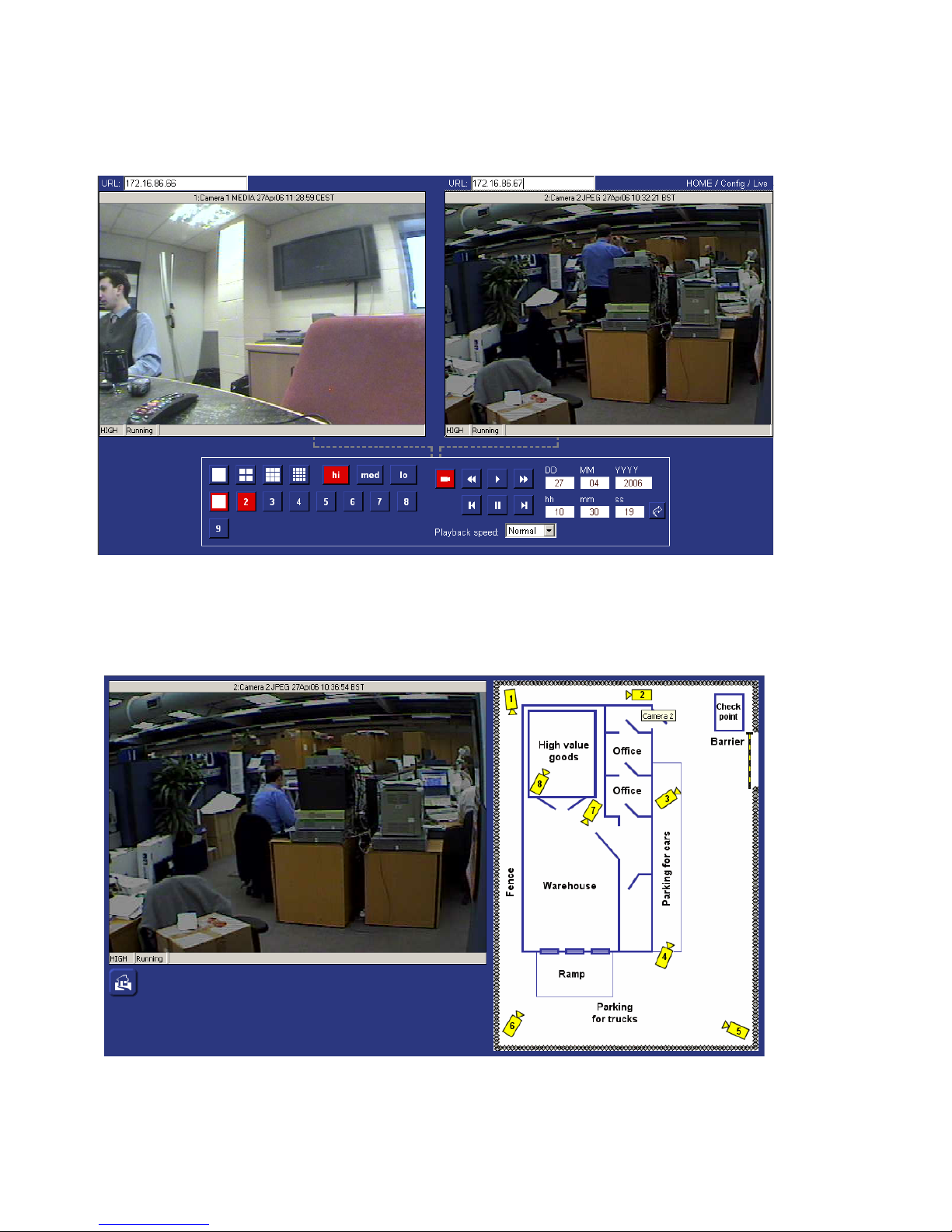
Multisite
The multisite screen allows the Operator to connect to two different NetVu Connected units, images from
both sites can be simultaneously viewed. Each site can be individually controlled.
Camera Map
It is possible to create a map showing the location of cameras. Cameras can then be selected and viewed
within this page, there are no controls available.
Dedicated Micros © 2006 13
Page 15

SSyysstteemm IInnffoorrmmaattiioonn
System Location
The system information option allows the Operator to select the System Location button, this will show details
on where the TransVu is currently located.
This page will show the Longitude and Latitude co-ordinates for the unit and will provide the option to connect
to either streetmap.co.uk or mapquest.com to find the exact position.
It also details the speed at which the vehicle is travelling where the TransVu is installed and the course the
vehicle is taking.
Current Position
When the TransVu is configured to be an SMS Server this page is provided as the User interface to allow
access to the log information sent from the other TransVu’s to this unit.
Access is available to all vehicles in the fleet and collation of the information can be filtered by time and date.
The events can be selected from a drop down list and the position of the vehicle at the time of the event
being registered can be determined using streetmap or mapquest.
Note: This web page will only be available if the TransVu is configured as an SMS Server.
14 Dedicated Micros © 2006
Page 16

Veehhiiccllee GGPPSS ppoossiittiioonnss
The following page is available when the TransVu is operating as an SMS server. The same SMS server
functionality can be provided by the DVIP video server.
To view these pages carry out the following steps:
1. Enable the unit to be an SMS Server, select Network ->SMS Setup.
2. Tick the SMS Server option and Save Settings.
3. Select Home -> Home to display the original web page, There will be two new options System Location
and Current Position.
4. Select Current Position to display the following screen.
Dedicated Micros © 2006 15
Page 17

SSyysstteemm LLooccaattiioonn
Important Note: Internet access must be available to utilise this feature.
System GPS position (latitude and longitude), speed (knots or nautical miles, statute miles and kilometers)
and course (compass direction), is automatically loaded from the NMEA data stream from the GPS unit.
If a zone has been defined that will be displayed.
If the unit can access the internet one of two map providers can be used to show position of the unit.
STREETMAP.CO.UK gives fine level detail for the United Kingdom while MAPQUEST.COM has world wide
mapping, to street level in the US and at street level for the larger world cities.
16 Dedicated Micros © 2006
Page 18
Configuration Options
The Configuration Option provides access to the on-board configuration web pages and allows the
Administrator to program the functionality that is supported on the TransVu.
When this option is selected you will be prompted for a user name and password, the default settings are
dm and web.
Note: It is recommended that the default username and password be changed once the configuration has
been completed, this will ensure no unauthorised personnel gain access to the configuration web
pages.
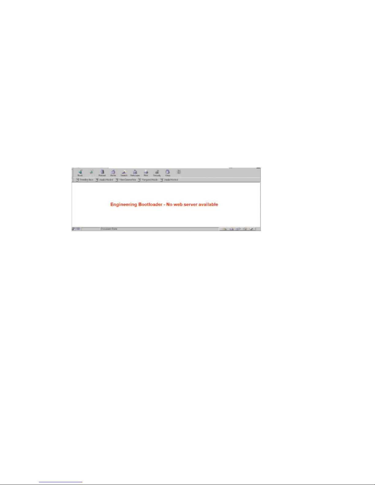
EEnnggiinneeeerriinngg BBoooottllooaaddeerr
If for any reason there are no webpages loaded on the TransVu or the unit has been re-powered more than
five time in one hour an Engineering Bootloader page will be displayed.
If this occurs telnet (or use HyperTerminal) to the unit and type “Reset” at the command prompt to reset the
unit. Contact Dedicated Micros Technical Support for assistance, contact details can be found on the cover
of this manual.
Note: The unit attempts to exit engineering mode every 15 minutes and resume normal operation.
Dedicated Micros © 2006 17
Page 19
HHoommee MMeennuuss
The Home menus provides access to the viewing options (Live and Demo Pages), returns the unit to the
Start Page and the Main Set-up page.
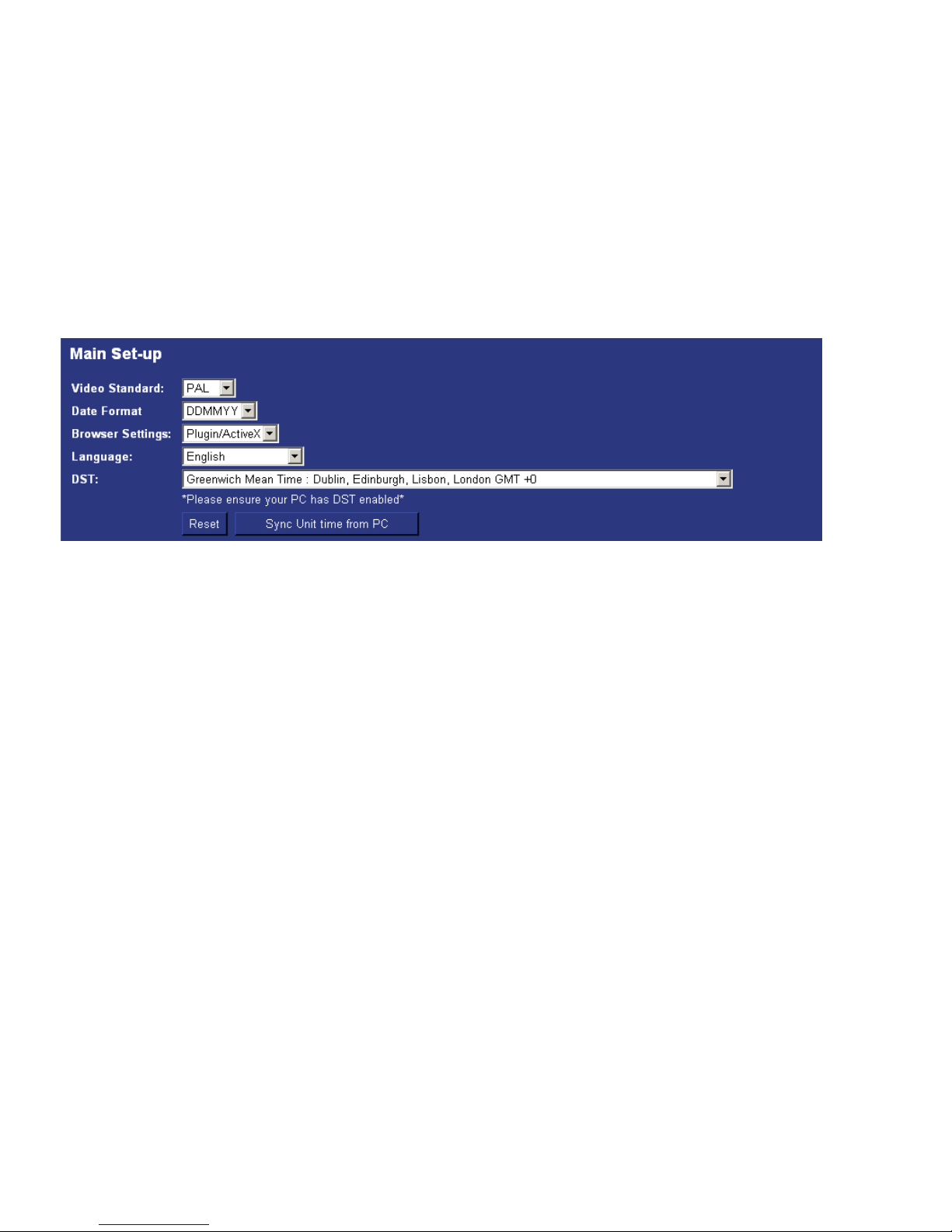
Main Set-up
The main set-up page provides configuration for global parameters that will affect the overall system; video
standard for the video inputs, browser format for the web interface, language that the menus will be displayed
in and the DST (daylight saving time) settings.
The web page also contains information on the unit, this information can be used for system diagnostics and
is useful when contacting Dedicated Micros for technical support.
Function Description
Video Standard
This is a global setting for all the video inputs on the unit. The video format can be
configured as PAL or NTSC.
When the video standard is changed it is necessary to Save Settings and then the unit
must be reset.
Date Format
It is possible to identify the format in which the date will be displayed; the default setting is
Day Day, Month Month, Year Year.
Browser Settings
The browser interface on the TransVu supports Active X or Java, the most appropriate for
your application can be selected from a drop down list. Again this is a global settings and
therefore any user connecting to the system will be presented with the same interface.
Language
The unit web configuration pages can be displayed in the language that is most suitable
to the country of installation.
The currently languages supported are; English, Spanish, French, Czech, Italian, Russian,
Dutch, Portuguese, German, Turkish, Croatian, Danish, Finnish, Norwegian, Hungarian,
Swedish, Polish, Arabic, Chinese.
DST
Daylight Saving Time. This reflects the time zone that the TransVu is installed in, select
from the list for the most appropriate time.
Reset
This will reset the unit.
Sync Unit time
from PC
The unit can be synchronised with the PC that is being used to configure the unit. If the
PC is synchronised with the network clock then this time will be reflected on the unit.
The synchronisation is not a persistent and will only synchronise the unit and the PC at
the time the option is selected.
18 Dedicated Micros © 2006
Page 20
Cameras Menus
The Camera Menus are the configuration pages directly associated with the video inputs. These allow the
camera inputs to be enabled, identify image resolution, set record rates, etc.
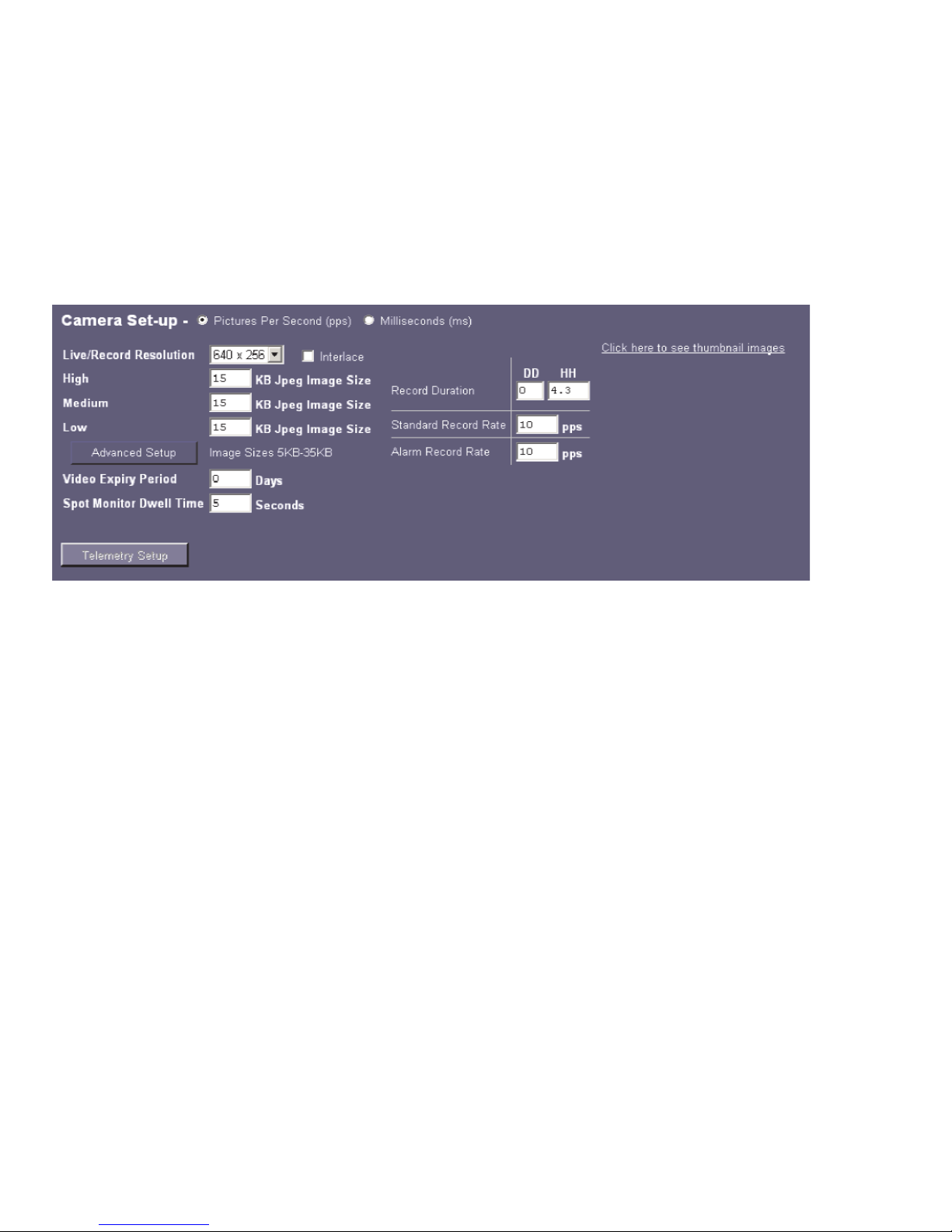
Camera Set-up
The camera set-up page allows global settings and individual camera settings to be configured.
Note: TransVu is physically configured for seven camera operation. Camera input eight is now set up as a
spot monitor input. The Spot Monitor is an analogue output capable of full screen or full screen
sequence with a programmable dwell time.
Note: Reducing the file size will allow more data to be transmitted across the network, it is important to
remember reducing the file size will require the compression applied to be increased and this will
Function Description
Pictures Per Second (pps) /
milliseconds (ms)
This allows the record settings to be configured as either Pictures Per Second
or Milliseconds.
Live/Record Resolution
This is the resolution of the live and recorded images that will be transmitted
from the TransVu and recorded to hard disk.
PAL Fields 640 x 256, 720 x 256, 768 x 288, 720 x 288
NTSC Fields 640 x 240, 720 x 240.
Interlace
Enabling this option will apply interlace to the video images.
High
This is the maximum file size for the images when high quality video has been
selected to be recorded or viewed.
The unit records images at the high resolution settings as standard.
Medium
This is the maximum file size for the images when medium quality video has
been selected to be viewed.
Low
This is the maximum file size for the images when low quality video has been
selected to be viewed.
Dedicated Micros © 2006 19
Page 21

affect the quality of the image.
WARNING: When running the unit at maximum Record Rate (50pps or 20ms in Standard Record Settings),
this will affect viewing and network transmission, as the video codecs will be running close to capacity the unit’s priority is to record the footage to the internal HDD, so transmission performance will be
reduced. This is exhibited by slow connection to the html pages and reduced viewing frame rates.
Multi-user viewing will also be affected. It is not recommended to set the Standard Record rate to 20ms
for everyday usage, but rather only for specific situations where this rate is necessary.
Function Description
Advanced Setup
This option gives access to the configuration page to allow alias configuration for the
MPEG4 mode, refer to the Advanced Setup section below.
Video Expiry Period
This indicates the maximum time any images can be stored on the hard disk, if the
record duration is less than the video expiry period the images will automatically be
overwritten.
Spot Monitor Dwell
Time
The unit supports an option Spot monitor output where a single or a sequence of
cameras can be viewed full screen. If a sequence is to be displayed identify the time
period each image is to be displayed on the monitor.
Record Duration
The total record time available in (DD) Days and (HH) Hours. This indicates the
storage capacity of the system without any alarm recording. This is estimated from
size of video storage, the standard record rate and the requested target size of the
recorded images.
Note: Changing the Record Duration will automatically update the Standard Record
Rate. Changing the Standard Record Rate will likewise update the Record Rate.
Standard Record Rate
This is global setting and identifies the ‘common pictures per second’ for all enabled
video inputs on the unit. This record rate will be allocated unless otherwise actioned
(Alarm or Variable Record Rate). It can be set in milliseconds or the number of
pictures per second.
The delay between consecutive images from any one camera is the Standard Record
Rate multiplied by the number of cameras being recorded. Changing the Standard
Record Rate will automatically update the Record Duration. Changing the Record
Duration will likewise change the Standard Record Rate.
Example Record Rates show the pps and the equivalent ms:
100 picture per second or 40ms
50 pictures per second or 20ms
25pps or 40ms
20pps or 50ms
10 pps or 100ms
8pps or 125ms
5 pps or 200ms
2pps or 500ms
1pps or 1000ms.
20 Dedicated Micros © 2006
Page 22

Note: The unit will try and compress the colour contents of the image if this box is not enabled, ticking this
box will remove unnecessary overhead on the compression process.
Function Description
Connected
It is necessary to enable the video inputs that have a video source connected. By
default only video input 1 is enabled.
Note: TransVu is physically configured for seven camera operation. Camera input eight is now
set up as a spot monitor input. The Spot Monitor is an analogue output capable of full
screen or full screen sequence with a programmable dwell time.
Title
It is possible to allocate an ASCII camera title to each of the enabled inputs, this
along with the camera number will be displayed on the screen to identify the camera
selected.
Recording
Each camera can be individually enabled to be available for recording. If this is
disabled then the camera will not be recorded.
Note: These can be set from the Schedule menu. See Schedule description.
Terminated
As the unit supports loop through it is necessary to remove the termination of any
inputs that are ‘looped’, by default all inputs are terminated at 75 ohms.
Mono
If the video input on the unit has a black and white (monochrome) source connected
then enable the corresponding camera.
Function Description
Alarm Record Rate
This identifies the global alarm recording rate which will be activated if an alarm is
triggered on the unit. For example, the unit may be configured to increase the recording
rate when a door contact is triggered.
Click here to see
thumbnail images
This will display a thumbnail view of video connected to the unit. Place the cursor in the
camera title box to view the corresponding video input.
Dedicated Micros © 2006 21
Page 23

Advanced Setup
The TransVu supports MJPEG (Live and Recording) and MPEG4 (Live and transcoding of MJPEG recorded
images) compression. The Advanced Setup option allows the JPEG settings to be aliased for when MPEG4
mode is selected. This will allow the User Interface to dynamic switch between viewing MJPEG or MPEG4
images.
Note: The TransVu records MJPEG whilst simultaneously supporting the option to transmit MPEG and
MPEG4 images for viewing
Function Description
System Resolution
This is a read only section and identifies the resolution as configured in the
Camera Setup page.
Resolution Codes
There are a number of resolution codes that identify the size of the image that
will be transmitted when the corresponding resolution button is selected in the
User Interface.
Note: These figures are automatically calculated by the unit are are
dependent on the Resolution setting selected in the Camera Setup
JPEG (Kbytes)
This is the maximum JPEG file size for each of the resolution options, enter
the values in Kbytes.
MPEG4 Bitrates and Frame
rates
This is the maximum bit rate and required framerate when the unit is in
MPEG4 mode for each of the resolution options, enter the value in
kbits/second and pictures per second (respectively).
Function Description
Spot Monitor
Cameras can be displayed in the Spot monitor, enable the cameras that are to be
included in the Spot monitor sequence.
Telemetry
This is currently not supported and is available for future expansion.
Camera Fail Reporting
If the video input on the TransVu does not identify a 1V peak-to-peak signal then the
unit can transmit an alarm notification for camera failure on the corresponding video
input.
22 Dedicated Micros © 2006
Page 24

Function Description
Resolution alias
This identifies the functions that are supported on the TransVu that can be
selected within a viewing application as well as the record resolution of the
MJPEG images.
Resolution codes
This drop down list displays all the previously configured resolutions and
allows any of these to be selected for the associated function. The illustration
shows that the record resolution and the resolution when the High option is
selected in the viewing application has been set to 2CIFLO, while the Medium
resolution is set for CIF and Low is set for QCIF.
Dedicated Micros © 2006 23
Page 25
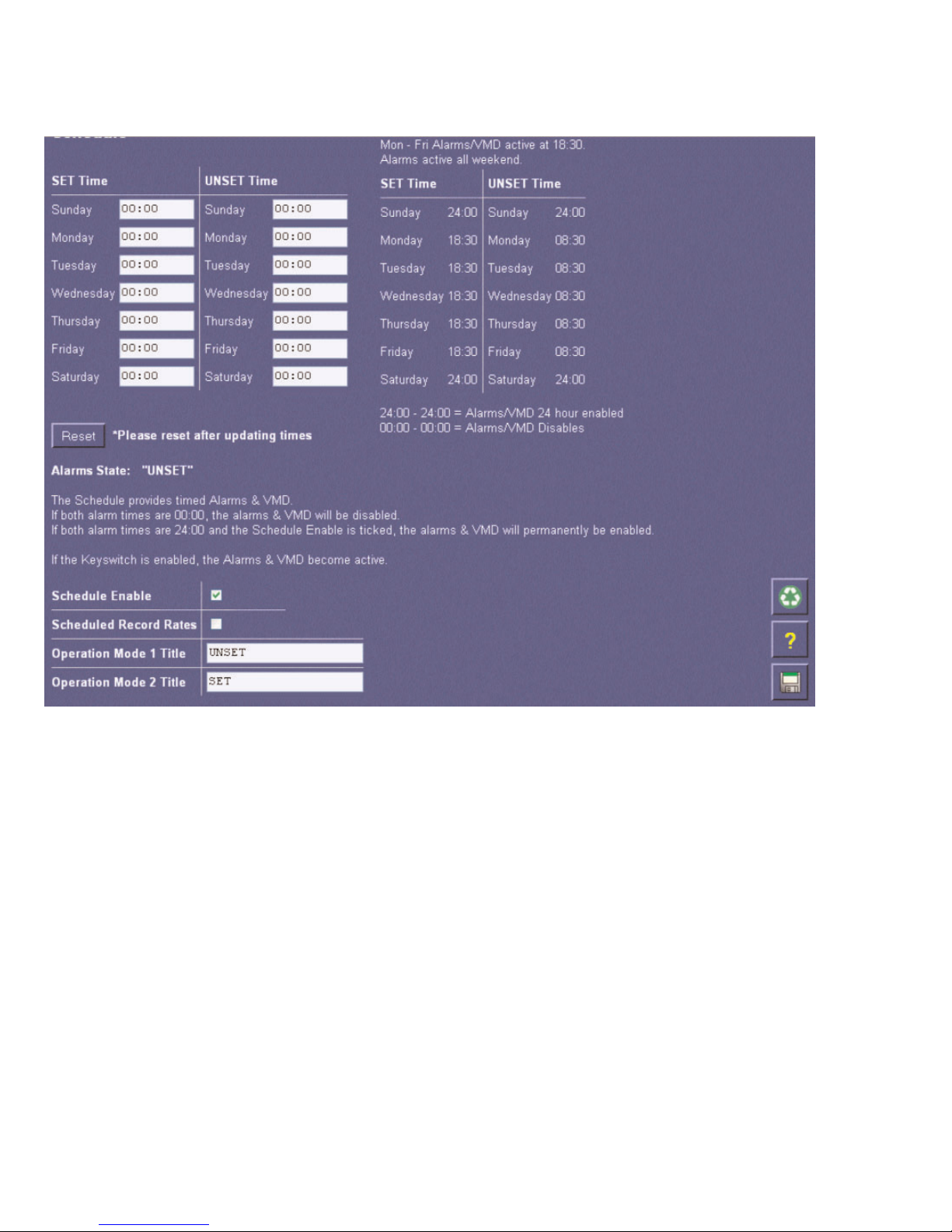
Schedule
The TransVu can be set up to automatically activate alarms and VMD at specific preprogrammed times.
Function Description
Schedule
This is a seven day schedule that allows alarms and VMD to be enabled or disabled at
times during the day
SETTime
This identifies when the unit will enable alarms and VMD.
UNSETTime
This identifies when the unit will disable alarms and VMD.
Reset
The unit must be reset if the times are changed.
Schedule Enable
Enable the schedule function so the unit can switch between the set and unset mode
Scheduled Record
Rates
Enable Scheduled Record Rates to have the unit operate in different modes depending
on the time of day, e.g. day and night operation may have different record times for night
time operation. This must be enabled to ensure the schedule affects the recording
Operation Mode
Title
These titles help identify the mode of operation for each Mode
24 Dedicated Micros © 2006
Page 26
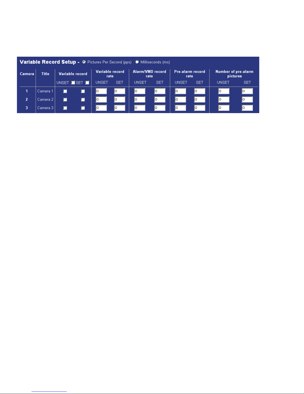
Variable Record Rate
Each camera on the TransVu can be individually configured to have a variable record rate depending on the
operation of the unit, this will allow you to have cameras with higher importance recorded at a higher frame
rate.
Function Description
Pictures Per Second Milliseconds
The variable record rate can be configured as pps or ms.
Ensure the information entered is in the correct format.
Variable record
By default all the video inputs are disabled, this allows you to enable individual inputs
for variable recording.
If Scheduled Record Rates has been enabled in the Schedule menu, there will be
two columns. The left column will enable the feature when the unit is in Set Mode,
the right column will enable the feature when the unit is in Unset mode. Note that the
Mode names will reflect any changes made by the user.
Variable record rate
This is the pictures per second or milliseconds that the unit will record in normal
operation (i.e. non alarm mode), if the camera is only to be recorded in an alarm
situation leave the setting at 0.
See Note 1 below
Alarm/VMD record rate
This is the pictures per second or milliseconds that the unit will record when the
corresponding video input has identified VMD or has been triggered by an external
alarm.
See Note 1 below
Pre-alarm record rate
This is the pre-alarm pictures per second or milliseconds that will be recorded along
with the alarm images.
See Note 1 below
Number or pre-alarm
pictures
Although the pre-alarm record rate is set it is also necessary to identify the number
of pre-alarm pictures.
If ‘Scheduled Record Rates’ has been enabled in the ‘Schedule’ menu, there will be
two columns. The left column will be the number of pre alarm pictures when the unit
is in ‘Set’ Mode, the right column will be the record rate when the unit is in ‘Unset’
mode. Note that the Mode names will reflect any changes made by the user.
Note 1
If ‘Scheduled Record Rates’ has been enabled in the ‘Schedule’ menu, there will be
two columns. The left column will be the record rate when the unit is in ‘Set’ Mode,
the right column will be the record rate when the unit is in ‘Unset’ mode. Note that
the Mode names will reflect any changes made by the user.
Dedicated Micros © 2006 25
Page 27
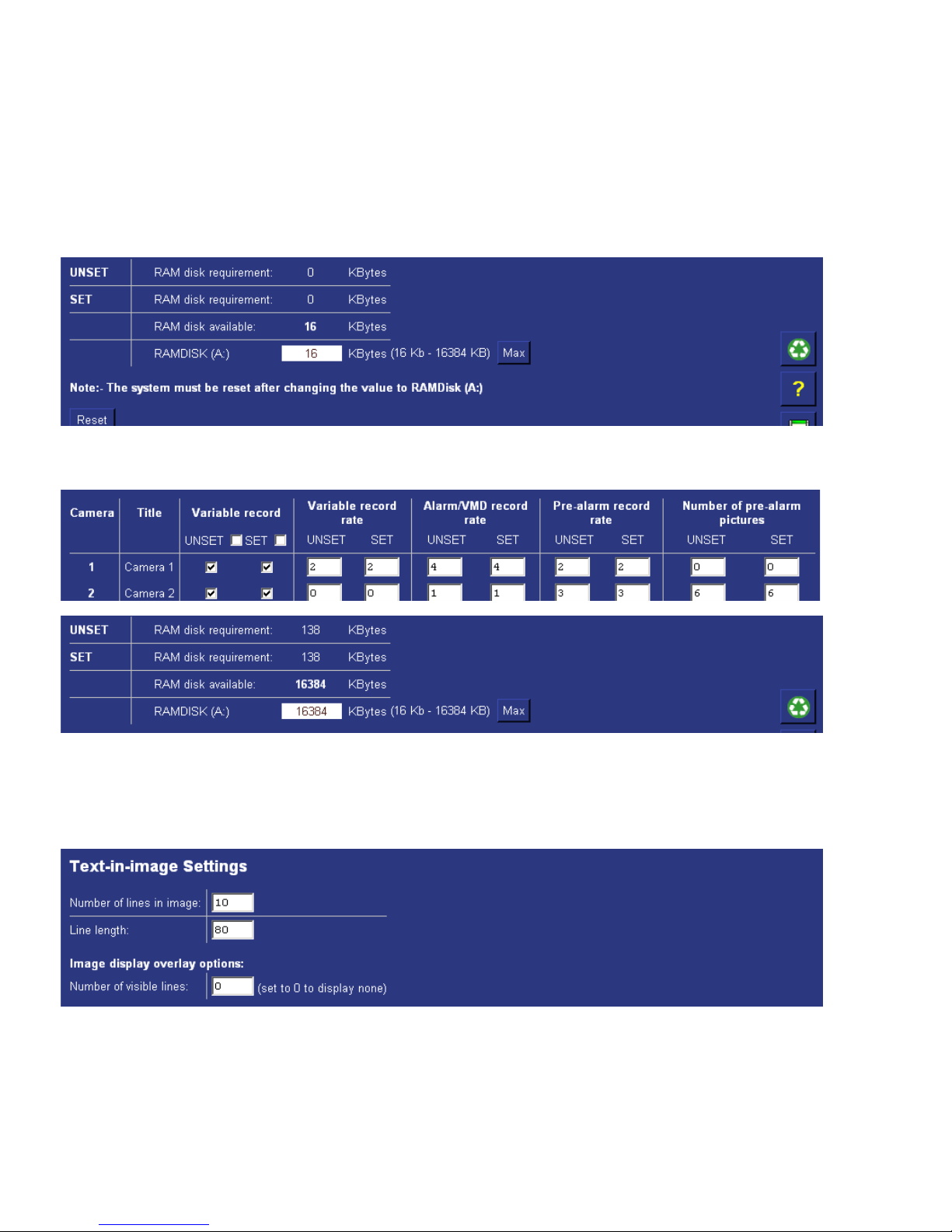
RAM Disk
This indicates how much RAMDisk is available for pre-alarm images. This allows the operator to monitor the
RAMDisk allocation and ensure as you configure your variable record settings you have sufficient RAMDisk
to accommodate the number of images required on alarm; i.e. variable record rate, alarm/VMD record rate,
pre-alarm record rate and number of pre-alarm cameras.
Note: If ‘Scheduled Record Rates’ has been enabled in the ‘Schedule’ menu, there will be two rows, showing
the requirement for each Mode.
The screen shows the settings for camera 1 and camera 2 and how much of the RAMDisk would be required
for these settings.
Text-in-Image Settings
It is possible to integrate text information into the TransVu system. This text data can be saved alongside the
video information and can be used in the search process for review.
Note: It is necessary to enable Text In Image on one the supported serial ports for Text-in-Image to operate,
refer to the Serial and telemetry Ports section of this manual.
26 Dedicated Micros © 2006
Page 28

Tip: When viewing video in Live view (Active X only) it is possible to left mouse click over the image and
the text information is superimposed over the image.
Alarms/VMD Menus
Alarm Inputs
The TransVu supports a number of alarm inputs, these can be individually enabled within the menu to allow
the unit then to be configured to carry out specific actions on the receipt of an alarm.
Function Description
Number of lines in
Image
This is the number of lines that will be displayed in live and replay (via the web
pages) along with the relevant images. The default setting is 10 lines.
Line length
This identifies the length of the lines that will be stored with the image. The default
setting is 80 characters which is generally the full screen.
Number of visible lines
To enable the text information to be viewed in the Live page it is necessary to identify
the number of visible lines.
Dedicated Micros © 2006 27
Page 29

Function Description
Alarm Module
Address
The TransVu supports six on-board alarm inputs and sixteen virtual alarms that are
associated with scripting (refer to Dedicated Micros Technical Support for more
information on scripting).
The address identifies which of the inputs are being configured; the on-board alarms of
the TransVu (address 1) or the virtual alarms of the TransVu.
Input
This corresponds to the alarm input on the unit.
Enabled
Each input must be enabled for it to be functional; if the input is not enabled and an alarm
is received the TransVu will not acknowledge the alarm.
By default none of the alarm inputs are enabled.
EOL (End Of Line)
Contact
This is part of the advanced alarm features option and is applicable to the on-board
alarms only. It allows the alarms to detect changes in the current, e.g. 0 – 800 Ohms will
result in a Tamper Alarm (short circuit) being detected.
By default the EOL contacts are disabled for each input.
Normally Closed
Contact
This applies to both the on-board alarms and the additional alarm module, that can be
connected to the TransVu via the 485-bus. When an input is enabled by default it will be
normally closed, removing the tick in the normally closed box makes the corresponding
input normally open going closed for alarm.
Nuisance Count
This is a repetitive detector value. When an alarm is received on the TransVu, the unit will
store the alarm time and will monitor the number of times the same detector is triggered
within an hour period. If the detector is triggered the number of times that has been set for
the nuisance count then the unit will de-activate this detector from triggering and alarm on
the system for an hour. The TransVu will continue to monitor the detector and check how
many times it is triggered during this hour, if it is triggered the same number at the
nuisance counter it will remain de-activated for another hour, this will continue until the
trigger value goes below the nuisance count setting.
Stuck Time
If any of the alarms/detectors are active for a period longer than specified then these will
automatically be omitted. This time period is set in minutes.
Pulse extension
This identifies the minimum duration of the alarm event. This time period is set in
seconds.
28 Dedicated Micros © 2006
Page 30

Alarm Zones
A virtual zone can be created to instruct the TransVu to carry out a number of actions on receipt of an alarm.
It is possible to configure upto 32 alarm zones.
The following are the actions that can be allocated to each of the alarm zones, these will be actioned on
Function Description
Alarm image
protect period
This is the time period in days that the alarm images will be protected from being
overwritten, when this time period elapses the images will be automatically overwritten.
Note: When protecting an image it is important to remember that the TransVu saves files
in 50 Megabyte blocks, the whole block that contains the image will be protected. If the
image overlaps into another block the all associated blocks will be protected this can start
to reduce the hard disk capacity available for storing images. To unprotect images refer to
Alarms/VMD>Protect/Unprotect Images.
Protect alarm
images indefinitely
Protecting the alarm images indefinitely will ensure the alarm images are never
overwritten.
Note: This section must be used in conjunction with Alarms/VMD>Protect/Unprotect
Images.
Alarm entry timer
(seconds)
This is the number of seconds set for the user to disable the alarms. If the alarm is not
disabled within this period then the alarm will be triggered.
Alarm exit timer
(seconds)
This is the number of seconds from the alarm being set to allow the user to exit the set
zones. If the user is still within the set zones after this time period the alarm will be
triggered.
Dedicated Micros © 2006 29
Page 31

receipt of the corresponding alarm.
Function Description
Select Zone
Cameras
This allows you to select one or more cameras that will be associated with the Alarm Zone
being configured. Each camera will become part of the ‘alarm sequence’ when this alarm
zone is triggered.
Zone on entry route
This is part of the Advanced Alarm Features and will create deferred alarms while the
entry time is active.
The primary alarm input will initiate the ‘entry counter’ to count down; this has specific
alarm areas associated with it. If someone enters the specified alarm areas during the
count down process the alarm will not be triggered allowing them to reach the alarm
panel to switch the alarm off.
Zone on exit route
This is part of the Advanced Alarm Features and will create deferred alarms while the exit
timer is active.
This is the similar to the zone on entry option, but works in the reverse, this allows an
Operator to switch on a building alarm and will give them a set time period to exit the
building and allow them to pass through specified alarm areas without triggering the
alarm.
Entry initiator
This is part of the Advanced Alarm Features and will trigger the entry timer if the system is
set. This is a count down timer that will automatically start when the ‘primary’ alarm trigger
(e.g. front door) is actioned and this ensures the alarm system is not activated by other
specified alarm triggers for the set time.
Exit terminator
This is part of the Advanced Alarm Features and will when enabled will instantly set the
alarm rather than waiting for the set countdown time.
Text Only Alarm
A text message, without any image attachments, will be transmitted when the alarm zone
is triggered. This may be used in situation where a camera is not associated with an
alarm zone.
30 Dedicated Micros © 2006
Page 32

Function Description
Switch System into
SET Operation
mode
This is the system set option which will enable all alarms and VMD for all zones.
Create Database
Entry
An alarm entry will be added to the database, the zone title will be used as part of the
entry information.
Change Standard
Record Rate
This will change the record rate of the cameras that have been identified in the Standard
Record Rate page (refer to Camera Set-up for information on how to configure standard
record rate). The cameras will switch to the alarm record rate specified.
Change Variable
Record Rate
This changes the record rate of the cameras that are selected in the alarm zone to the
variable record rate previously specified (refer to How to Configure Variable Record Rate
in this section of the manual). Each of the cameras must have an alarm record rate
specified.
Connect/Dial on
Alarm
The TransVu will automatically connect to the remote alarm monitoring station defined.
Note: The Viewer application requires an unlock code for this function to operate.
24 Hour Alarm
This will force the alarm zone to be permanently active (24/7).
Record still image
This will record a still image of the trigger along with the standard recording. Still images
are accessible through the Live page of the web interface. This will also add the word
‘alarm’ to the title header.
Protect Alarm
Images
Any alarm images associated with the alarm zone will be protected from being
overwritten. To unprotect the files refer to Alarms/VMD>Alarm Image Protect/Unprotect
Images.
Archive Alarms
This will force the alarm images to be automatically sent via FTP to a central FTP server,
refer to How to Set up Connect on Alarm in this section of the manual.
Switch Spot Monitor
to Primary Camera
When an alarm is triggered it is possible to switch the Primary Camera to be displayed on
the Spot Monitor output. This requires the parameter ‘24 Hour Alarm’ to be enabled.
Dedicated Micros © 2006 31
Page 33

VMD
The TransVu supports VMD (Video Motion Detection) on all video inputs and allows cameras to automatically
detect if there is any movement/changes within the video scene, this can then trigger a number of operations.
Note: It is recommended that you utilise the Walk test function to ensure the settings are correct for each
input enabled, if the settings are to low this will mean VMD will not be identified to high and false
alarms will occur.
Function Description
Primary Camera
This is the primary camera and will be the image displayed when the event is triggered, it
is also the input the snap-shot will be taken from if e-mail image is selected.
Goto Preset
It is possible to action one of the selected cameras to go to a preset position when an
alarm zone is triggered.
Email Image
When e-mail on alarm is enabled it is possible to attach an image to the e-mail, the
resolution of the image must be defined. It is important to consider the speed of the link
between the TransVu and the SMTP Server that the e-mail will be sent to. The resolution
options available are; thumbnail, high resolution, medium resolution and low resolution.
32 Dedicated Micros © 2006
Page 34

Function Description
VMD Camera
Enable
This option will display all the video inputs on the TransVu, each input can be individually
enabled for VMD. Tick the box that corresponds to the input to have VMD enabled.
VMD pulse
extension
This allows you to extend the time that an alarm is valid, If there is an occurrence of VMD
identified on one of the inputs and the duration is only one second in length then the pulse
extension will increase this time period, this will ensure the recording contains sufficient
information.
Note: If VMD occurs again within this pulse extension it will only be acknowledged as a
single trigger.
VMD pre-alarm
time
This is the time period prior to the VMD trigger where the images will be saved and
protected along with the trigger itself.
VMD alarm
duration
This is the period of time that the VMD alarm will be in alarm mode, i.e. the period of time
the alarm action allocated will be active, e.g. increased recording.
VMD protect
period
Any VMD entry in the database can be protected from being overwritten, this is the period
of time the files will be saved and protected. After this time the files will be automatically
overwritten unless specified.
Protect VMD
images indefinitely
It is possible to protect VMD images indefinitely to ensure any incidents are saved and
protected for review at a later date. These files will remain protected until specified
differently.
Live & DuoView
Display
It is possible to utilise the web interface to monitor live and recorded video, if the Live or
DuoView are to be used it is possible to identify when VMD has been triggered, squares
will appear over the area where there is movement.
Dedicated Micros © 2006 33
Page 35

Function Description
Create Database
Entry
This will record an event in the database using the VMD Zone number (refer to Alarm
Zone below for more information).
Change Standard
Record Rate
This will set the alarm record rate across ALL cameras that are enabled in the record
sequence.
Change Variable
Record Rate
This will change the record rate of the corresponding camera ONLY, make sure the
camera is enabled in the Camera Input page (Refer to the Quick Start Guide for enabling
video inputs).
Report on VMD
Activity
This will automatically send a telnet alarm message to an allocated Viewer, when the PC
receives and accepts the alarm video is then requested, refer to Alarm/VMD Reporting for
more detailed information.
24 Hour Alarm
This will ensure that VMD is permanently enabled on the corresponding input (24/7).
34 Dedicated Micros © 2006
Page 36

Configuring VMD
The VMD cells can be configured to ensure the areas of concern are fully covered for motion detection.
Select the ‘Click here to see VMD applet’ option on the VMD page.
Function Description
Record Still Image
This will record (and mark the image by stating the word ‘ALARM’ in the title) still of the
corresponding video input alongside the recording of the event, access to the still is via
the Live Page.
Protect VMD
Images
This will protect the whole recorded 50 Mbyte block of video regardless of which
camera(s) are recorded.
Create Zone Input
This turns the VMD camera into an alarm input when used with the Alarm Zones page,
Select VMD1 instead of an alarm input to trigger the event.
Archive Event
This will mark the VMD event for automatic FTP download to the FTP Server identified,
refer to FTP Events Download page for more information.
Email Image
This will automatically e-mail a snapshot of the VMD incident to the SMTP server
identified, refer to Email configuration page for more information.
Email Image
Resolution
This identifies the resolution of the snapshot that will be attached to the e-mail; the options
available are thumbnail, low resolution, medium resolution and high resolution.
Dedicated Micros © 2006 35
Page 37

Clear Cells
Removes all defined zones from the image.
Default Grid
Displays the default grid of 16 VMD zones over the whole image.
Graticule On
Displays a grid to assist in identifying and creating zone areas.
Zone Display Only
This will display the areas of the image that are covered by a zone only and will assist you
in ensuring the necessary areas are covered.
Resolution
This is the resolution of the reference VMD image being displayed.
Refresh
This will update the reference image to the latest view during set up.
Function Description
Camera
This is a drop down list of the video inputs on the TransVu, selecting one of the inputs will
display the corresponding video source.
Zone
There are 16 advanced VMD zones that can be individually configured, select the zone
from the drop down list.
Mode
The zone mode identifies when the reference image is taken for triggering VMD. The
options are:
Normal - the reference image is updated approx. 1/second so this will only allow small
changes in the scene without triggering
Last trigger - the reference image is only updated when the VMD is triggered and would
be used under controlled lighting, i.e. so there are no false triggers due to ambient light
changes
Static - the reference image is collected on startup and is never updated. This would be
used in ‘sterile’ areas where there are no changes expected
Zone disabled - this will disable the zone mode.
Pixel Count (%)
This value is set as a percentage and equates to the percentage of pixels in the selected
zone that must change for the VMD event to be triggered.
Pixel Change (%)
This setting is a percentage value of the overall change required in the greyscale to be
included in the pixel count. The percentage change is defined over the complete range of
black to white, a 100% pixel change would be from black to peak white.
36 Dedicated Micros © 2006
Page 38

Alarm Image Protect/Un-protect
Within the alarm and VMD configuration web pages it is possible to identify whether event images are to be
protected from being overwritten, this can be indefinitely of for a set period of time.
The alarm image protect/un-protect web page offers the ability to protect images post recording, i.e. images
that are stored on the hard drive and are not protected from being overwritten. It is also possible to increase
the selected time period for images that are automatically protected as configured in the alarm and VMD
web pages.
Alternatively the web page also offers the option to highlighted existing protected recordings and un-protect
these so they can be overwritten.
Function Description
Start Time and
Date
This allows you to enter the start time and date for the period you wish to search for
recorded images.
End Time and
Date
This allows you to enter the end time and date for the period you wish to search for
recorded images.
Dedicated Micros © 2006 37
Page 39

Database Configuration
The TransVu supports numerous logs which will store information on the actions and processes the unit
carries out. It is necessary to ensure the database can support and register all events.
The database configuration web pages gives information on the database of the unit and also allows the
maximum number of entries to be identified.
Function Description
Last database
reset time
This is a read only section and is generated by the TransVu, it identifies the last time that
the database was reset.
Current number of
entries
This is a read only section and is generate by the TransVu, it identifies the current number
of entries in the database.
Maximum number
of entries
This is the maximum number of events that will be logged in the database. When this
figure is reached the database will start overwriting the entries starting at entry 1.
Function Description
Protect Image
Partition Summary
The recorded files will be displayed within the area. These are then selected to either
unprotect or protect.
Unprotect Images
Any images that have been previously protected and are selected in the protect image
partition summary section will be unprotected, these files will then be overwritten.
Protect Images
Any images that have not been protected or require the protect period extending can be
selected in the protect image partition summary and then the time the images are to be
protected can be identified in days.
Protect Images
Indefinitely
If images are never to be overwritten the they can be protected indefinitely.
38 Dedicated Micros © 2006
Page 40

Alarm/VMD Reporting
When an alarm is triggered the TransVu will send a message via the serial port or over the network using
PPP.
This section identifies the details of the receiving station and the route the message will take.
When using the Ethernet network to transmit the alarm message all configuration for the remote receiving
station can be carried out using the web interface, to enable PPP via a modem the ‘profiles’ (\etc\profiles) file
will need to be edited.
Function Description
Primary Host
This is the IP address or name of the initial host that the TransVu will transmit an alarm
message to.
Secondary Host
If the TransVu is unable to contact the primary host then it is possible to identify an
alternative route and a secondary host.
If there is only one alarm receiving IP address, you must enter the details in both the
primary and secondary connection settings.
Profile
This is the medium that the TransVu will use to make the connection to the primary or
secondary host.
Note: If the connection is via the serial port the profile will be the username configured in
the ‘profiles’ file in the \etc directory on the TransVu.
Dedicated Micros © 2006 39
Page 41

Function Description
Public (NAT) IP
Address
If the TransVu is to be available on a public network but the unit IP address is not a public
IP address, it will be necessary to allocate a public IP address to enable connectivity
across the network.
Video Server Port
(port forwarding)
If port forwarding is to be used when making a connection, enter the port number that the
Network Administrator will provide.
Unit Alarm Name
This is the name that will be presented to the remote alarm viewing application and
therefore should have some significance to the Operator. This name must match the
defined folder name in the Viewer folder tree.
Remote Alarm
Reporting
This must be enabled for the TransVu is to automatically connect on alarm, it must also
be enabled in the Alarm Zone option.
Remote Camfail
Reporting
If the TransVu identifies camera failure on any of the inputs enabling this option will force
the TransVu to connect to the remote alarm station.
Remote Tamper
Reporting
This is part of the Advanced Alarm Features and will send an alarm report when the
TransVu has identified a tamper alarm.
Remote Startup
Reporting
This is part of the Advanced Alarm Features and will send an alarm report when the
TransVu starts up, this will identify any system resets.
Dial Retry Time
If the initial connection attempt fails then the TransVu will wait for the specified time period
before attempting to re-connect.
Dial Limit
This identifies the number of times the TransVu will attempt to connect to the remote
alarm monitoring station after a failed attempt, a setting of 0 identifies no limit and the
TransVu will continue to try and connect until it is successful.
Alarm telnet Server
Port
This identifies the port number that the remote monitoring station has allocated for
‘listening’ for alarm messages from the TransVu.
40 Dedicated Micros © 2006
Page 42

System Menus
Serial Ports & Telemetry
The TransVu supports a number of serial ports that can be connected to peripheral devices. This menu
allows the serial mode, serial device and serial parameters to be configured for each port.
Dedicated Micros © 2006 41
Page 43

Telemetry Setup Page
1. To access the set up parameters of the camera select the Telemetry Setup button on the Camera Set-up page.
Note: When you select the Telemetry Setup button, it may take a few seconds for the page and video to be
downloaded, during this time do not press any buttons as this will slow the process down.
2. The video from any of the cameras on the unit along with the telemetry control buttons for testing will be
displayed.
Function Description
Telemetry Image
Compression
This specifies the image compression used when telemetry motion is active. Selecting
maximum compression (255) will result in fast, very low resolution updates to allow
telemetry control over slow connections. Selecting minimum compression (8) displays
high resolution images for use with high speed connections. This will help improve the
image when controlling a functional camera.
Baud rate, parity,
data bits, stop bits,
flow control
These are the default settings of the selected serial device. Refer to the relevant
manufacturer manual for the peripheral serial device for this information.
Telemetry Setup
This button will be active when a telemetry protocol has been configured. It allows the
operator to configure the telemetry commands such as save presets.
These would then be used in conjunction with the Viewer application.
Function Description
COM1 and COM2
The port usage that can be assigned to COM 1 and COM 2 is; off, debug, general
purpose, PPP, text in image and LED box.
Modem/TA
When the serial port has been configured for PPP it is necessary to select from one of the
supported modems to identify the device connected to the unit.
COM5 and COM6
The port usage that can be assigned to COM 5 and COM 5 is; off, debug, general
purpose, telemetry, text in image and LED box.
Telemetry type
This is the list of serial telemetry protocols that are supported on the TransVu.
Telemetry Matrix
Monitor
Matrices support many monitor outputs, this is the monitor output that has been allocated
for connection to the TransVu.
Telemetry Offset
This is the matrix offset to allow any camera input on the matrix to be set as input 1 on
the unit. An example of this is in large systems where multiple operators are allocated
groups of cameras, for ease of use each camera can be configured to start at camera 1.
However they could actually be connected to any input on the matrix but we would select
camera 1 which could be controlling input 32 on the matrix.
42 Dedicated Micros © 2006
Page 44

This allows you to view any of the enabled inputs on the TransVu, control the telemetry connected to the
system and set up any features that are required for your application; such as presets. You can also access
the camera menus from this page allowing you to configure parameters that are only programmable from the
camera menu.
Note: Review the relevant documentation for the camera to see how you navigate the camera menus.
Remember to save any configuration settings in the dome menu!
Important Information
It is possible to use VMD (Video Motion Detection) on moveable cameras, however to ensure that moving
the camera does not trigger false alarms the VMD will only be active when the dome is in preset position 1
(home position). This ensures that VMD is only active when the camera is viewing the field of view that the
VMD mask corresponds to, moving the camera away from preset 1 will automatically inhibit VMD detection
on the camera. As soon as the camera receives the command to ‘return to home’ the VMD will be
automatically re-enabled.
Note: It is necessary for the ‘return to home’ command to be issued so that the TransVu is aware the
camera is back at preset position 1, leaving the camera to return to preset 1 after a dwell time will not
be sufficient to re-enable the VMD functionality.
Dedicated Micros © 2006 43
Page 45

Telemetry Control
The TransVu unit requires an adapter (Amplicon 485HF9) for telemetry control, which is available from
www.amplicon.co.uk. This converts the RS232 signal to RS485, enabling the TransVu unit to communicate
directly with a single dome camera.
To connect a camera via the adapter:
1 Enable Pelco-P in serial port telemetry
2 Set Com 1 or 2 to 9600 Baud, 8 bit polarity, 1 stop bit, flow - none.
3 Save settings
4 Enter the Camera setup menu. Enable 485 Telemetry control for the designated camera.
5 Save settings.
6 Reset the TransVu unit. Once the unit reinitialises, PTZ control will be available.
Audio Recording
TransVu supports two audio inputs which can allow for external audio equipment to be connected. This allows
the Operator to communicate via the Viewing software across the network to the camera location.
The audio is independent of the video inputs which means any camera can have associated audio
equipment, e.g. Intercom system. The audio can also be recorded alongside the video to allow a
simultaneous review of both.
To enable the audio to be recorded:
1. Select Configuration Pages > System > Audio Recording
2. Enter the Title for Audio channel 1
3. Tick the Enabled box to enable recording of audio channel 1
5. Enter the Title for Audio channel 2
6. Tick the Enabled box to enable recording of audio channel 2
8. Press the disc icon to save the settings
EN
GND
B
A
A’
B’
GND
VDC
9Way
female
‘D’ type
Amplicon
485HF9
www.amplicon.co.uk
Part No. 90986433
Ground
Dome
5-12 VDC
Power out of TransVu 12V DC
Ground of TransVu
TransVu
Com
1or2
9Waymale
‘D’ type
on TransVu
DM TransVu Harness
(DM/HARN/TRV)
44 Dedicated Micros © 2006
Page 46

9. Reset the unit for the audio settings to be applied.
Note: Audio is available in Live monitoring at all times. The audio will only start recording after the
Record Audio option has been enabled.
Function Description
Audio Channel
Audio equipment can be connected to the TransVu to allow bi-directional audio to be
integrated into the system. There are two audio channels this identifies the channel being
configured.
Title
This title will be saved alongside the recorded audio, ensure this has significance to the
system.
Record Audio
This option must be enabled for the audio to be recorded with the video, audio is
continuously available in live mode but this option must be enabled for audio in record
mode.
Dedicated Micros © 2006 45
Page 47

PPoowweerr MMaannaaggeemmeenntt
The TransVu supports power management capabilities, this menu allows the power management settings to
be configured. Auto power management stops the unit recording and closes down operation 15 minutes (or a
user defined time) after the vehicle ignition is turned off. TransVu will also carry out a controlled and timed
power down sequence when the vehicle voltage has fallen below a user set level, this ensure the battery is
not drained.
An additional cable from the “Ignition On” connection on the vehicle is taken to the TransVu alarm input 5,
which is Pin 11 on the multipole connector.
Managed Power Shutdown
There are three conditions when power management can shut the machine down:
1.Power down after an interval (user set timeout in seconds) from when ignition has
been turned off.
2. Power down after an interval (user set timeout in seconds) from when voltage drops
below the (user set voltage) nominal supply level.
3. Power down immediately when the input voltage falls below the (user set voltage)
minimum operating supply.
Managed Power Up
When power management has been enabled the unit will only power up when the following conditions have
been met:
The power to the unit exceeds the (user set) minimum operating supply voltage.
The ignition sense line receives a positive voltage above 7.5 volts.
Gnd
20
11
38
Power in
Power on
relay
Power out
to camera
32
Ignition key
+
-
Vehicle
Power
Supply
TransVu
46 Dedicated Micros © 2006
Page 48

Power Sensing Circuit
When enabled the Power Sense circuit (PIC 0) will respond by either opening or closing the internal power
relay.
This controls power to the TransVu power supply and the power out connector, which will normally power
cameras and ancillary equipment.
This ensures that when the power sense circuit shuts down the TransVu, all cameras etc. are also shut
down, removing the load from the vehicle battery.
Current drain in the powered off condition is 30 milliamps.
Power in
38
Low voltage sense
Ignition sense
Ignition
11
Power
sense
(PIC 0)
TransVu
power
Supply
32
Power out
TransVu
Dedicated Micros © 2006 47
Page 49

PPoowweerr MMaannaaggeemmeenntt Weebbppaaggee
The TransVu power management is enabled on this page.
Ignition off Timeout (secs)
This is the time from when the ignition is switched off until the unit shuts itself down automatically. In the above
example 900 seconds = 15 minutes.
The ignition supply of the vehicle must be wired into alarm 5 for this feature to work. The input senses ignition
voltage above nine volts.
Low supply Timeout (secs)
When the voltage drops below the nominal operating supply setting (in the example, ten volts) the unit powers
down after the set time (30 secs in the example above).
If the voltage rises above the nominal setting the countdown is cancelled.
Minimum operating supply (volts)
This is the minimum voltage at which the unit will power up.
If the voltage drops below this level, the unit powers down immediately.
Nominal operating supply (volts)
When the voltage supply to the unit falls below this (user specified) level the unit powers down after the time set
for low supply timeout.
48 Dedicated Micros © 2006
Page 50

RReeccoommmmeennddeedd SSeettttiinnggss ffoorr PPoowweerr MMaannaaggeemmeenntt
Ignition off timeout is usually set between ten and thirty minutes, depending on periods when the vehicle
may have the engine switched off, but recording must continue.
Low supply timeout should be set for a longer period than when the vehicle power is likely to be held low,
such as starting the engine from cold.
Minimum operating supply should be higher than 7 volts and less than the nominal operating supply setting.
Nominal operating supply should be set to a few volts less than the vehicle’s normal power supply.
The following examples are typical for 12 and 24 volt systems:
12 volt systems
24 volt systems
Dedicated Micros © 2006 49
Page 51

Remote Set / Unset
This page is used to set or unset the system remotely for a period of time. This remote set will overwrite the
current state of the system until the specified duration is exceeded OR there is a set / unset event local to the
site (i.e. keyswitch / keypad). If the system is set by timer, a change in state from the timer will not override
the remote set state.
Advanced Features
The TransVu supports a number of advanced features, each of these can be enabled or disabled depending
on what the system requirements are.
Enabling the features in this menu will display the corresponding configuration pages.
Function Description
Ignition off Timeout
(secs)
The ignition off timeout specifies how long the TransVu will continue to operate after
the ignition input is switched off.
Low supply timeout
(secs)
The low supply timeout specifies how long the system should operate for after the
power supply drops below the specified low voltage threshold.
Typically this would be indicative of a weak battery.
Minimum operating
supply (volts)
The minimum operating voltage specifies the absolute minimum supply voltage at
which the system will power up.
Nominal operating
supply (volts)
The nominal operating voltage specifies the voltage at which the system enters the low
voltage timeout.
Power Management
Enabled
This option must be enabled if power management is required.
50 Dedicated Micros © 2006
Page 52

Section Feature Description
Home Register
Note: Configuration and registration of the TransVu is carried out at
the factory, therefore this screen is for fault diagnostics only and it is
recommended that the page is not enabled unless advised by
Dedicated Micros Technical Support.
Cameras Text in image
It is possible to integrate the TransVu into an application where
receipt of specific text can be used to trigger an alarm. This will
enable the configuration page to be included in the Cameras tab.
Alarms Alarm image
protection
It is possible to configure the TransVu to protect images within
parameters set by the operator (time and date, etc). This will enable
the configuration page to be included in the Alarms/VMD tab.
Dedicated Micros © 2006 51
Page 53

GPS Menus
GPS Configuration
The TransVu supports GPS (optional) this menu is used to configure SMS reporting and logging of GPS
messages.
Section Feature Description
Alarms Database
configuration
The database can be set to have a maximum number of entries to
ensure efficient management of the information. This will enable the
configuration page to be included in the Alarms/VMD tab.
Alarms Alarm/VMD
reporting
It is possible for the TransVu to send information to a remote
monitoring station under certain conditions (camera fail, alarm, etc).
This will enable the configuration page to be included in the
Alarms/VMD tab.
GPS GPS Data
Logging
The TransVu supports the option to have an additional GPS module
transmitting NMEA configured, enabling this option will create an
additional configuration page to be displayed, this will be within the
GPS tab.
GPS Accelerometer
Support
The TransVu can be integrated with the accelerator system of the
vehicle, enabling this option will display the configuration page to
allow settings to be entered, this page will be within the GPS tab.
Network Automatic FTP
Download
The unit can be configured to automatically download information
using FTP, This will enable the configuration page to be included in
the Network tab.
Network SMS reporting
The TransVu can be configured to send data to an SMS server This
will enable the configuration page to be included in the Network tab.
Network Email reporting
The TransVu supports e-mail of data under certain conditions (alarm,
start up, etc). This will enable the configuration page to be included in
the Network tab.
Network Webcam support
The TransVu can make any of the video inputs available to a web
server for use within a web page. This function uses FTP to upload
the images to the web server. This will enable the configuration page
to be included in the Network tab.
Network Firewall
configuration
The TransVu supports an on board firewall to ensure no unauthorised
users can access the unit. This will enable the configuration page to
be included in the Network tab.
52 Dedicated Micros © 2006
Page 54

Function Description
SMS timed report
Enable the features so that an SMS message is transmitted every ‘n’ minutes if the
position of the unit changes.
Enter the time in minutes between each message transmission.
SMS distance
report
Enable this feature so that the unit sends an SMS position message every ‘n’ nautical
miles, the statute miles and Kilometers are approximated from the nautical miles value.
The distance travelled will be reset each time the position is updated by a timed report,
zone change or on/off track message.
Section Feature Description
Tools Scope, Audio
Trace, Relays,
Variables
There are a number of tools that can be used to obtain information
on the system performance, enabling this options will display the
relevant pages in the Tools tab.
Live options Telemetry
controls
It is possible to enable or disable the telemetry control capabilities of
the Live web page on the TransVu. Disabling would prevent a User
from taking control of any functional cameras on the unit.
Live options Event controls
The Live page supports the option to allow the User to access the
event database on the TransVu, this can be enabled or disabled.
Live options Playback controls
Playing back of recorded images stored on the TransVu is possible
via the Live page, the option to allow the User the ability to review
the recorded video can be disabled.
Dedicated Micros © 2006 53
Page 55

GPS tracking route
Routes are defined as a collection of zones, this must be selected to allow the SMS and
database events to be generated on zone changes.
Default tracking
radius
The tracking route when selected defines a set of points which can be interpreted as a
straight line, the tracking radius determines the maximum radius between the points
where the route does not follow a straight line. If the TransVu goes beyond this radius an
event will be triggered.
SMS report on
zone change
Enable this option to send an SMS position message every time a new zone is entered on
the specified route.
Periodic offtrack
report period
OFFTRACK messages will be sent at specified intervals if the vehicle leaves the selected
route, enter the time period between the messages. An ONTRACK message will be sent
when the vehicle returns to the specified route.
Database event on
zone change
Enable this option to create a database event entry every time a new zone is entered on
the selected route. Offtrack and On track events will be generated when the vehicle
leaves the route and returns to the route specified.
Trackpoint Interval
Enter the mileage intervals for a new trackpoint to be added to the local track data file.
Note: 0 disables the distance based updates.
Track data files are created every time the unit starts up, the filename consists of the
startup tim and the files are stored in date directories.
Trackpoint Period
Enter the time in seconds for a new trackpoint to be added to the local track data file.
Note: 0 disables the time based updates.
Track data files are created every time the unit starts up, the filename consists of the
startup tim and the files are stored in date directories.
Ignore Navigation
Warning
This setting allows the GPS system to be used in Simulation Mode for demonstration
purposes.
Note: This option is always cleared on the unit with a system startup.
54 Dedicated Micros © 2006
Page 56

Accelerometer Event Setup
This page is used to specify the maximum acceptable G values in each direction. Any G levels above these
values will create an entry in the database.
Note: The default values assume the TransVu is mounted in the vehicle with the connector towards the rear
of the vehicle.
Function Description
x-axis
This identifies the -ve and +ve G values for the x axis of he TransVu.
Y-axis
This identifies the -ve and +ve G values for the y axis of the TransVu.
G-events enabled
This option must be enabled for operation.
Axis Title
The text name for each axis can also be specified and this appears as the event
title in the database.
Dedicated Micros © 2006 55
Page 57

Network Menus
Network Settings
The TransVu supports a 10/100BaseT auto detecting network connections, by default the units is set for DHCP
and will automatically be allocated an IP address on power up. This menu allows the unit to be configured with a
fixed IP address and allows the network bandwidth settings to be selected.
Function Description
IP Address, Subnet
Mask, Default
Gateway
This is the fixed IP address and subnet mask, and if applicable default gateway, it is
recommended that the unit be configured with a fixed IP address as it is possible with
DHCP that the address may change with each power up.
Primary DNS
This is the primary DNS server IP address for applications that are utilising domain
names.
Secondary DNS
This is the IP address of the secondary DNS server in case of failure of the primary
server.
System Name
This is the name that is allocated to the TransVu, this will be used when transmitting
alarm information to a Remote Monitoring Station.
PPP IP
This is the IP address that will be allocated if the unit is to dial (in and out) on alarm using
PPP. This is independent to the units IP address.
56 Dedicated Micros © 2006
Page 58

Function Description
DHCP IP
If the TransVu was installed on a DHCP network this would be the IP address the DHCP server
allocated on power up of the unit.
DHCP Subnet
If the TransVu was installed on a DHCP network this would be the subnet of the network the unit
is connected and would be automatically allocated by the DHCP server on power up.
DHCP Gateway
This is the IP address of the default gateway (router) that the TransVu would be automatically
assigned to by the DHCP server.
DHCP Name
This would be the name of the TransVu that is automatically allocated by the DHCP server.
Serial Number
This is the serial number of the TransVu, this is a read only section.
LAN, WAN, ISDN
These have default settings for the following information, selecting these will automatically
allocate values to these settings:
LAN – 10000 Kilobits/second.
WAN – 256 Kilobits/second.
ISDN – 64 Kilobits/second.
Force 10BaseT
operation
The TransVu supports 10 or 100BaseT full or half duplex transmission, this will force the unit to
operate at a 10BaseT connection.
Maximum Trans Rate
This controls the bandwidth of the Ethernet or PPP connection made by the unit.
Transmit Image
Buffers
This is used in order to improve the picture delivery over Ethernet when using a slow
connection, i.e. 256Kbps. Options available are 1, 2 or 3 buffers.
Ethernet MTU
This is the maximum transmit unit for the Ethernet packet. By default this figure is set to
1514bytes.
TCP Re-Transmit
Timeout
This is the time the TransVu will wait to re-send a packet if an acknowledgement is not received.
When making a connection across a WAN link this figure should be increased and should match
the timeout figure for the router.
Dedicated Micros © 2006 57
Page 59

Firewall Option
The TransVu supports an on-board firewall to add to the security of the unit. When the firewall is enabled it
will work in conjunction with the security applications that are already present in the network.
This feature ensures that unauthorised users can not gain access to the TransVu and therefore tamper with
the operation of the system. The firewall analysis the requested access right down to IP address and port
number filtering and is designed to let the authorised people access and keep un-authorised people out.
Function Description
PPP Idle Line
Timeout
This is the time the TransVu will wait before dropping the PPP link if data has not been
transmitted.
PPP Link Down
Timer
If for any reason the connection is lost then this is the time period before the TransVu will
be forced to drop the PPP connection.
Packet Size
This is the maximum packet size that will be transmitted from the TransVu. This figure is
identified in Bytes.
Secondary Web
Server Port
If the default port setting for web serving has already been allocated it is possible to
configure a second port number.
Eg. If the secondary web port is set for 8000 because the default (80) web port is blocked
by the network or firewall. To obtain images from the TransVu enter the IP address plus
the secondary web port in the address section of Internet Explorer or in the Viewer;
http://172.16.1.2:8000
(<IP address><:><secondary port number>).
58 Dedicated Micros © 2006
Page 60

Port Allocation
The following are the default port settings supported on the TransVu; this is shown on the Firewall page
menu.
FTP Events Download
The TransVu can transmit images via FTP (File Transfer Protocol); this can be on receipt of an alarm or
VMD or using a scheduled time to backup the recorded video.
Function Description
Enable PING response
from server
By default this option is enabled and allows the TransVu to be pinged. Disabling this
option will make the unit less visible on the network.
Allowed IP address
These are the IP addresses and subnets that the TransVu will allow connections
from, i.e. the IP address of the host PC’s that will connect to the TransVu to; review
video, download information.
Note: If you enable this function ensure the IP address of the PC you are using to configure
the system is also in the list. If the address is not added then you will be unable to
communicate with the unit via the network, it is important to take this feature into
account when the TransVu is on a DHCP network where IP addresses are allocated
automatically.
If no IP addresses are specified than any host can connect to the TransVu.
Open TCP ports
This list identifies the TCP ports that are on the system and available. If a host tries
to communicate with the TransVu using a TCP port that is not in the list, even with a
valid IP address, the host will not gain access to the unit.
The enabled ports can be a range or single port address, if a single port is needed
then enter the same port number in the to and from section.
Open UDP ports
This is the list of UDP ports that are available on the TransVu. If a host tries to
communicate with the TransVu using a UDP port that is not specified in the list, even
with a valid IP address, the host will not gain access to the unit.
The enabled ports can be a range or single port address, if a single port is needed
then enter the same port number in the to and from section.
Dedicated Micros © 2006 59
Page 61

In a TransVu application this ensures that images from multiple vehicles are stored in a central location.
Function Description
FTP Server
Identify the IP address, URL or name of the FTP server the TransVu will connect to for
FTP download of recorded images.
FTP Control Port
The default reserved port number for FTP on most Ethernet networks is port 21, if this
port has already been allocated on the network for other purposes identify an alternative
port number.
FTP Root
Drive/Directory
Enter the directory information for where the recorded images are to be stored.
It is recommended that a name associated with the unit name be used for ease of
retrieval.
Username
To access an FTP Server it is necessary to go through an authentication process, obtain
the username and password from the Network Administrator and enter the username
required to gain access to the FTP Server.
60 Dedicated Micros © 2006
Page 62

SMS Setup
The TransVu supports the feature to transmit an SMS text message to a SMS Server for forwarding to a
mobile phone.
This gives the option to automatically or manually action the TransVu to send a text message to inform an
Operator of an incident.
The typical process for SMS messaging is:
The TransVu transmits a message to the remote mobile phone, this can be on receipt of an alarm or
manually initiated.
The Operator then has the option to;
Send a message back to the Server
Function Description
Password
To access an FTP Server it is necessary to go through an authentication process, obtain
the username and password from the Network Administrator and enter the username
required to gain access to the FTP Server.
On Connection
This section identifies when the FTP is to be initiated, this option will force the TransVu to
automatically initiate the FTP download when the unit detects a change in state of the
Network port (network down to network up).
Scheduled and
Schedule time
This option must be enable for the TransVu to initiate an FTP download at a scheduled
time, identify the time of day that the images are to be downloaded.
Polled and Poll
time
To initiate and FTP download at regular intervals enable this option and enter the time
interval in minutes.
Note: The time period is the time between the end of one FTP download to the start of
the next.
Manual only
It is possible to manually initiate an FTP download, enable this option to allow an
Operator to start the download process.
Clear video
protection after
download
Any images that have been protected from overwritten can have the protection
automatically cleared when they have been downloaded from the TransVu, this will ensure
the disk space is made available for images to be written to.
Watermark each
partition after
download
The TransVu supports the ability to add a unique watermark to image partitions that are
downloaded from the unit.The file will be stored as a text file along with the downloaded
video, the watermark is also logged in the log file of the unit.
Server Directory
This is a read only section and identifies the main directory on the FTP server where the
images will be stored. The FTP Root Drive / Directory previously configured will be
created under this main directory.
Start Download
When Manual Only is selected an Operator can begin the FTP download process by
selecting the Start Download option.
Dedicated Micros © 2006 61
Page 63

Log onto the unit using the web interface or viewing software or
If a central monitoring station is commissioned to monitor the video the Operator can send a message
back to the TransVu to action the unit to send an alarm message to the central monitoring station (the
message will include the information in the text it has received from the Operator) who can the make a
video connection to the unit and verify the incident.
Function Description
Destination
Number
This is the GSM number for the mobile phone / SMS server. Enter the number, this should
be entered in international format including the country code and local area code.
62 Dedicated Micros © 2006
Page 64

Function Description
Destination URL
This can be the URL or the IP address of the SMS Server when utilising SMS over
TCP/IP. The messages will be sent over an Ethernet link if present, alternatively it will be
sent over the GSM network. Enter the information in this section.
SMS Server
The TransVu can act as a SMS Server, enabling this will allow the TransVu to accept and
log SMS messages.
Note: The Verbose option must not be enabled when this option is selected.
Report startup
This option must be enabled if the TransVu is to transmit a SMS message when the unit
starts up, this will identify any unplanned system resets.
Report alarms
Enable this option to ensure the TransVu transmits a SMS message on receipt of an
alarm via the on-board or additional alarm inputs.
Report camera fail
The TransVu can detect if any of the enabled video inputs goes below the required 1 volt
peak-to-peak, enable this option so that a SMS message can be transmitted when
camera fail is identified.
Report VMD
activation
Video Motion Detection can be detected on each of the TransVu video inputs, enable this
option so that the TransVu transmits a SMS message when VMD is detected on any of
the enabled camera inputs.
Verbose messages
For the TransVu to send a message that can be read by the operator this option must be
enabled, this ensures the message transmitted to the mobile is in a format that can be
understood by the operator.
Note: This format is not supported in standard SMS Servers.
Callback profile
For a return message to be accepted identify the route the message will take, i.e. the
message from the Operators mobile device.
The return message must contain the SMS command password, callback IP address (IP
address of the remote PC with the viewer application) and the command to action the
TransVu to call the remote station.
SMS command
password
Enter the password to enable the SMS commands to be initiated, this will also be included
in the return text from the Operator.
Last signal
strength
This is a read only section and identifies the signal strength of the GSM module.
Last bit error rate
This is a read only section and will detail the error rate of the GSM module.
Dedicated Micros © 2006 63
Page 65

Advanced Settings
Email
The TransVu can automatically transmit an e-mail to an SMTP Server under numerous conditions; on start
up, on receipt of an alarm, camera failure and identification of VMD.
As the TransVu by it’s nature is not continually monitored this feature ensures constant visual (if selected)
communication is available between the unit and the monitoring station when certain events occur.
Function Description
Service Centre
Number
This page is specifically for configuration of the GSM module connected to the TransVu.
Enter the number for the service centre that will be responsible for the SMS message.
GSM PIN Number
Enter the pin code for the SIM card in the mobile device that will receive the SMS
message.
Note: If any changes are made to this page the Pin number must be re-entered each
time.
GSM/SMS Port
Enter the port address that will be used for the SMS message to be transmitted/received.
64 Dedicated Micros © 2006
Page 66

Function Description
Connection Profile
It is possible for the e-mail to be transmitted via the Ethernet network or dial up
connection. This setting presumes that a modem has been connected and configured and
the TransVu is connected to a WAN and has been allocated a valid IP address.
Mail Server
This will identify the SMTP Server that the TransVu is to communicate with.
Enter the IP address or DNS name of the SMTP Server, the server will then forward the email on to the recipient.
Recipient
Enter the e-mail address and display name of the intended recipient.
Reply to
If the recipient is to respond to the e-mail enter the e-mail address and display name or
where the response is to be sent.
Note: The TransVu does not accept e-mails so this must be a valid e-mail address.
Sender
These optional fields indicate the source of the e-mail notification. If the fields are left
blank the TransVu will automatically use the system name & DNS name to create a
sender name.
Email reports
Select the conditions under which the TransVu will transmit an e-mail; when the TransVu
has been reset, when an alarm zone has been triggered, if any of the video inputs has
detected camera failure, if VMD has been identified on any of the enabled video inputs.
Email Logging
The TransVu logs events within a database, for the transmission of an e-mail to be logged
this option must be enabled.
Dedicated Micros © 2006 65
Page 67

Webcam Set-up
Any of the video inputs on the TransVu can be made available to be transmitted, via FTP, to a webserver.
These images can then be incorporated into a web page and accessed via a standard web browser.
This function gives users the opportunity to incorporate video images into their Corporate web site or used for
advertising on the vehicle the TransVu is installed on.
The setup is separated into:
Upload Settings
Camera Selection
Webcam Settings
Function Description
FTP Server
Enter the IP address, URL or Domain Name of the FTP Server where the images are
to be transmitted. Images will be uploaded from the TransVu to this FTP server at the
time intervals specified.
FTP Root
Drive/Directory
Enter the root drive / directory on the FTP server where the uploaded images are to
be saved.
FTP Image Directory
Identify the directory that will be automatically created when the initial image is
uploaded to the FTP Server.
66 Dedicated Micros © 2006
Page 68

Function Description
Camera selection
Enable the camera inputs that are to be accessible for webcamera functionality.
Function Description
Image Filename Prefix
Each image that is uploaded from the TransVu can have an identifier that will be
stored as a prefix to the file name, this is useful in applications where multiple
TransVu’s are transmitting images to the same FTP Sever and allows easy
identification.
Username
To gain access to the FTP server it is necessary to go through an authentication
process enter the username (this can be obtained from the Network Administrator)
to allow images from the TransVu to be uploaded.
Password
To gain access to the FTP server it is necessary to go through an authentication
process enter the password (this can be obtained from the Network Administrator) to
allow images from the TransVu to be uploaded.
Update interval
Enter the minimum update interval between each image that is transmitted from the
TransVu.
Dedicated Micros © 2006 67
Page 69

Function Description
Single FTP session
Selecting single FTP session will avoid the login/logout procedure for each image
that is transmitted to the FTP Server. The TransVu will remain connected and logged
on to the ISP until the FTP connection is disabled.
Batch transfer
To transfer all camera images in one batch enable this option. When selected the
update interval is the delay between all images being updated.
Webcam Resolution
Identify the resolution of the images, defined in the Camera Setup Page, that are to
be transferred to the FTP Server.
It is important to take into account the speed and type of network link between the
TransVu and the FTP Server when selecting the webcam resolution.
Webcam Enabled
The webcam functionality can be enabled at specific times (SET, UNSET mode or
when undefined), always enabled or disabled. If the webcam functionality is to be
disabled it is recommended that the option also be disabled in the Advanced
Features option, refer to How to Enabled System Features above.
68 Dedicated Micros © 2006
Page 70

System Tools
Video Scope
This allows the video contents to be analysed.
Audio Trace
This allows the audio content (if enabled) to be analysed.
Sync Height
This not currently used.
Watermarking
The TransVu supports the facility to watermark recorded images.
It is also possible within this menu to produce a watermark certificate which can be used as part of the evidence
to prove that the recorded images have not been altered or tampered with. This is achieved with the allocation of
a unique MD5 signature which would change if the image files are altered.
This process can assist with the audit trail process for digital recorded video. The MD5 signature is a unique
signature that is automatically allocated by the TransVu by using file information and generating the unique
signature.
Function Description
Start Date and time
Enter the start time and date for the time period which you wish to allocate a
watermark to the recorded video.
End Date and time
Enter the end time and date for the time period which you wish to allocate a
watermark to the recorded video.
Report author
This will identify the Operator or Administrator responsible for generating the
watermark certificate and can be used as part of the audit trail.
Watermark step size
This is the step size in bytes used when calculating the watermark, if the step size is
set to 1 then every byte in the in the video partition will be part of the watermark
calculation.
Note: The smaller the step size the more information that is to be processed. The
process time will increase, this is displayed in the status bar.
Dedicated Micros © 2006 69
Page 71

System Variables
This page can be used for system diagnostics as it provides a readable overview of the configuration
parameters of the TransVu. Any information that has been configured and stored on the unit will be shown on
the file. Typical information is; camera titles, alarm title. It identifies the Value, Variable Name and the
Description.
Note: This information may be useful when contacting Dedicated Micros for system analysis.
Function Description
Partition Information
Summary
The partition information, within the set time and date, will automatically be
generated and displayed here, once generated each partition can be selected by
highlighting the file.
Partition Info
This is the initial step to commence the watermark process, when selected the
TransVu will search for the partition information within the set time and date. The
partitions are then displayed in the partition information summary area.
Get Index info
Step 2 is to get the index information on a particular partition, highlight the required
partition in the summary area and press this button.
Watermark
Step 3 is to generate the watermark, selecting this option will generate the unique
MD5 signature for the selected partition.
Create Certificate
Once the watermark has been generated this allows a certificate with all the
information on the watermark to be created, it is possible to print this certificate.
This watermark certificate can be used as part of the audit trail to identify that the
images have not been changed or tampered with.
70 Dedicated Micros © 2006
Page 72

Environmental
This web page contains information on the vibration and temperature of the unit and can be used for system
diagnostics.
Camera Masking
TransVu has the capability to identify if a video input has been covered (by hand, spray paint, etc.) to
prevent video images being viewed and recorded. The Camera Masking option identifies normal levels of
contrast and uses them as a base line. It then compares these against a user defined minimum contrast
level. If the video input goes below this user defined level an event is generated on the unit.
This web page allows the masking feature to be configured.
Script Features
The TransVu supports two internal scripting languages:
CBasic
CInterpreter
These can be used to allow the customer to adapt the operation of the TransVu for specific features.
Function Description
Camera, Title
This displays the camera number and camera title as configured on the
Camera Setup page.
Enabled
Enables or disables the feature on the camera.
Low Contrast Level
This figure corresponds to the contrast threshold the system uses to define
that a camera is masked. The default setting is 30, but as different
cameras have different characteristics, it will be neccessary to adjust this
figure to avoid false alarms.
Dwell
This is the delay the unit will wait before declaring the camera is masked.
Dedicated Micros © 2006 71
Page 73

This is used in conjunction with the Dedicated Micros Media Manager software.
This webpage provides an interface to the user for the multi media images that are configured within the
Media Manager software.
This section allows the operator to test the Media and Public Information operation.
Function Description
Slide show enabled
This option must be enabled to allow the configured images (slide show) to be
displayed on the monitor.
Time & Date
This option allows the time and date to be displayed (or disabled) within the
public information section.
Public information line
Enable the public information line to allow additional text information to be
displayed, this text could be useful information for the passengers.
Flash Public Information line
Enable this option to allow the Public Information message to flash on the
monitor.
Display offset
This is the horizontal pixel line number where the image will start to be
displayed from.
72 Dedicated Micros © 2006
Page 74

This section shows the status of the public information and can be useful when contacting Dedicated Micros
Technical Support.
Function Description
Test Text Dwell
This identifies the length of time that the public information will be displayed
on the monitor.
Test Text Flash
Enable this option for the public information text to flash when displayed on
the monitor.
Text information / Send
Once the webpage has been saved enter the text that is to be displayed within
the public information section and press send, this will be displayed on the
monitor.
Test image override / dwell
This allows a specific image to be displayed on the monitors. Enter the dwell
time that the image is to be displayed. Images are stored on the Media
TransVu in c:\override.
Image name / Send
Enter the image name and extension that is to be selected and displayed,
press the image button for the image to be immediately displayed.
Dedicated Micros © 2006 73
Page 75

System Logs
System Logs Set-up
The TransVu supports a number of system logs that can be used for system analysis, the logs can be
enabled or disabled depending on the system requirements.
Function Description
Log PPP connections
This will enable the logging of WAN connections using the PPP ports and will record
the IP address, the profile used and the local time of the attempted connection.
Log anonymous FTP
connections
This identifies when an unauthorised user tries to access the TransVu by entering
anonymous in the username or password.
Log illegal file access
Any web access to a CGI protected directory or non-existent file will be logged with
an IP address, time and type of action.
Log Telnet/FTP users
This will log users that are trying to gain access to the TransVu using an FTP or
telnet session.
74 Dedicated Micros © 2006
Page 76

Appendix A - SMS Configuration
IInnttrroodduuccttiioonn
The TransVu Video Servers support GSM communications and SMS messaging with a Siemens TC35i GSM
module. This allows the video servers to report events via SMS and to receive SMS messages in order to
create events on the system. On Video Servers supporting GPS modules, the SMS messaging can also be
used to report position, distance off track and current zone.
CCoommmmaanndd FFoorrmmaatt
Commands consist of a descriptor followed by a variable parameter list. Due to the limited message size
under SMS, the parameters do not have descriptors with them and must appear in the correct order. If a
parameter is not supplied, the parameter delimiter must still be include. The parameter list is defined for
each command. The command is delimited from the parameter list by ‘?’ and the parameters are delimited
by ‘&’.
SSMMSS CCoommmmaannddss
These are messages sent to the video server in order to create an event. These messages may be sent
from a mobile phone or Internet service offering SMS messaging. Optional parameters are indicated by {};
these should not be included in the SMS message sent to the system.
Callback
This command is used to cause the Video Server to make a connection to a Telnet listener at the
destination. The command specifies a callback profile to use so this can be used to initiate an Internet
connection from the server and report the dynamic IP assigned to that connection back to the destination.
CALLBACK?<password>&<destination>&<profile>&<text>
password SMS password to enable commands to be executed
destination
IP address or DNS name of the Telnet listener. A DNS name can only be used if
the server has a connection to a DNS server
profile
This can be a profile number to use or a profile name to make the callback
connection. The profile number relates to the profiles on the SMS configuration
webpage. Specifying a name allows any profile on the Video Server to be used but
the profile must exist. If the profile is specified as Ethernet, the system will attempt
to connect over the Ethernet gateway on the network
text The text to send to the Telnet listener
Dedicated Micros © 2006 75
Page 77

Make Ethernet Connection
This command is used to cause the Video Server to make an Internet connection via the Ethernet using
PING. As this connects via an external device eg a router, it relies on the Internet connection having a static
IP address.
OPENLINK?<password>{&<destination>}
password SMS password to enable commands to be executed
destination
Optional IP address or DNS name of the Internet server to be contacted. A DNS
name can only be used if the server has a connection to a DNS server
76 Dedicated Micros © 2006
Page 78

Position (GPS)
This command is used to query the current position of the video server. The server will send an SMS
message to the destination number specified on the SMS configuration webpage or to the number specified
in the command. The SMS destination number will typically be an SMS server but by specifying a mobile
phone number the lat./long position in decimal degrees can be reported to any mobile phone capable of
receiving SMS messages
POSITION?<password>{&<phone>}
SSMMSS RReeppoorrttss
SMS reports are messages sent from the video server to a defined SMS server when an event occurs. The
events that cause SMS reports are selected on the SMS configuration webpage.
Startup
STARTUP?<name>&<time>&<IP address>&<latitude>&<longitude>&<zone>
Name The system name
Time The local julian time of the message
IP address The Ethernet IP address, either programmed or DHCP address
Latitude Current latitude decimal degrees if known
Longitude Current longitude if known
Zone Current zone
password SMS password to enable commands to be executed
phone Optional mobile phone number to send the report to
Dedicated Micros © 2006 77
Page 79

Shutdown
SHUTDOWN?<name>&<time>&<latitude>&<longitude>&<zone>
Distance (GPS)
This message is generated if the unit has moved more than the distance specified on the SMS configuration.
This can be used to track a vehicle by reporting the position every 2 miles, for example.
DISTANCE?<name>&<time>&<lat>&<long>&<speed>&<course>&<zone>&<distance>
Name The system name
Time The local julian time of the message
Lat. Current latitude decimal degrees if known
Long Current longitude if known
Speed Current speed reported by GPS
Course Current heading reported by GPS
Zone Current zone
Distance Distance travelled since last message
Name The system name
Time The local julian time of the message
Latitude Current latitude decimal degrees if known
Longitude Current longitude if known
Zone Current zone
78 Dedicated Micros © 2006
Page 80

Zone Change (GPS)
This message is generated if the unit is using route tracking and changes zone on the specified route. The
message is issued when the unit enters a new zone.
ZONECHG?<name>&<time>&<lat>&<long>&<speed>&<course>&<zone>&<distance>
Offtrack (GPS)
This message is generated if the unit is using route tracking and is not in a valid zone on the specified route.
The message is issued when the unit leaves a zone and will be repeated every 5 minutes until it re-enters a
valid zone.
OFFTRACK?<name>&<time>&<lat>&<long>&<speed>&<course>&<zone>&<distance>
Name The system name
Time The local julian time of the message
Lat. Current latitude decimal degrees if known
Long Current longitude if known
Speed Current speed reported by GPS
Course Current heading reported by GPS
Zone Last valid zone
Distance Distance travelled since last message
Name The system name
Time The local julian time of the message
Lat. Current latitude decimal degrees if known
Long Current longitude if known
Speed Current speed reported by GPS
Course Current heading reported by GPS
Zone New zone
Distance Distance travelled since last message
Dedicated Micros © 2006 79
Page 81

Ontrack (GPS)
This message is generated if the unit is using route tracking and has moved into a valid zone after being
reported as off-track.
ONTRACK?<name>&<time>&<lat>&<long>&<speed>&<course>&<zone>&<distance>
Timed (GPS)
This message is generated periodically by the server. The time period is specified on the SMS configuration
page.
TIMED?<name>&<time>&<lat>&<long>&<speed>&<course>&<zone>
Name The system name
Time The local julian time of the message
Lat. Current latitude decimal degrees if known
Long Current longitude if known
Speed Current speed reported by GPS
Course Current heading reported by GPS
Zone Current zone
Name The system name
Time The local julian time of the message
Lat. Current latitude decimal degrees if known
Long Current longitude if known
Speed Current speed reported by GPS
Course Current heading reported by GPS
Zone Current zone
Distance Distance travelled since last message
80 Dedicated Micros © 2006
Page 82

Position Report (GPS)
This message is generated in response to an SMS message requesting the current position. (POSITION)
REPORT?<name>&<time>&<lat>&<long>&<speed>&<course>&<zone>
Alarm
This report is generated when the current active alarm list changes
ALARM?<name>&<time>&<active alarms>
Camfail
This report is generated when cameras fail or restore
CAMFAIL?<name>&<time>&<failed mask>
Name The system name
Time The local julian time of the message
Lat. Current latitude decimal degrees if known
Long Current longitude if known
Speed Current speed reported by GPS
Course Current heading reported by GPS
Zone Current zone
Dedicated Micros © 2006 81
Page 83

Appendix B - Units of Measurement
Latitude and longitude are specified in signed decimal degrees and conversion to NMEA (degrees & decimal
minutes), degrees, minutes & seconds, or radians is quite simple. North & East are positive angles and South
& West negative angles. Speed is reported in knots. Course is the true course over ground.
Example: Request and read a position report
The following string of text is an example request to find the GPS position, speed and course of a suitably
fitted system.
POSITION?QWERTY&+447777123456
The above message would be typed into a mobile phone or suitable SMS message generator with no
spaces.
POSITION Requests a position report
? Indicates a request
QWERTY Password for the system
& Separating character
+447777123456 SMS phone number to receive the report
The following SMS message is typical of the returned position report:
POSITION, TRANS§DEMO,
Thu Jan 09 16:00:00 2003, +0000,
54:58:30.91N, 2:31:57.06W, 78.2&214.1&NorthwichRoad
POSITION Type of report
TRANS§DEMO Name of the unit
Thu Jan 09 Day / Month / Date
16:00:00 Time
2003 Year
+0000 Offset from GMT
54:58:30.9N Latitude in degrees / minutes / seconds
2:31:57.06W Longitude in degrees / minutes / seconds
78.2 Speed (knots)
214.1 Course (degrees absolute)
Northwich Road User defined Zone
If Verbose Messaging is turned off the report would appear in this format:
REPORT?TRANS§DEMO&1014030907&53.305714&- 2.540652&37.6&214.1&NorthwichRoad
REPORT Indicates the following text is a report
TRANS§DEMO Name of the unit
1014030907 Julian time (number of seconds since 1st January 1970)
53.305714 Latitude
-2.540652 Longitude
37.6 Speed (knots)
214.1 Course (degrees absolute)
Northwich Road User defined Zone
82 Dedicated Micros © 2006
Page 84

? Limiter for description
& Separating characters
Example: Receiving a sample start-up message
STARTUP,TRANSVU§TEST,Mon Jul 08 09:46:23 2002 +0100, 0.0.0.0
DISTANCE,TRANSVU§TEST,Mon Jul 08 10:14:00 2002 +0100,
53:20:21.42N, 2:49:22.14W,26.1, 269.0, , 5.0
Dedicated Micros © 2006 83
Page 85

Appendix C - GPS serial port configuration
The file etc\paths.ini file needs to specify which serial port the GPS input is connected to and where the data
should be sent.
Example paths.ini file
[PATH1]
input_path=\COM6
output_path=\pipe\GPS
buffer_size=128
The com6 serial port (serial port 6) then needs to be configured at 4800,n,8,1 and the port function set to Text-inImages.
The above example sends the GPS data to be processed and does not send text to be displayed with camera
images.
84 Dedicated Micros © 2006
Page 86

Appendix D - GPS Routes
The system can support up to 5 routes for route tracking. The routes are defined as a series of zones in an INI
file named etc\routes.ini.
Each zone consists of a zone name, the zone radius and two endpoints specified in GPS format latitude &
longitude.
GPS format bearings are specified as degrees and decimal minutes and can be obtained from Autoroute or
similar programs.
Example routes.ini file
# Route name
[Frandley-Mews]
# zone name - string without spaces
zone=NorthwichRoad
# start & end points - reported in GPS format of degrees & decimal minutes
p1_lat = 53 18.36 N
p1_long =2 32.47 W
p2_lat = 53 18.63 N
p2_long = 2 36.61 W
# radius from each end point & perpendicular distance off track
radius = 1
zone=SchoolLane
p1_lat = 53 18.63 N
p1_long =2 36.61 W
p2_lat = 53 18.77 N
p2_long = 2 32.16 W
radius = 1
zone=BarbersLane
p1_lat = 53 18.77 N
p1_long =2 32.16 W
p2_lat = 53 19.83 N
p2_long = 2 31.24 W
radius = 1
zone=ArleyRoad
p1_lat = 53 19.83 N
p1_long =2 31.24 W
p2_lat = 53 20.53 N
p2_long = 2 31.97 W
radius = 1
Dedicated Micros © 2006 85
Page 87

When a zone name is detected, a new zone is created and can be followed by the radius and endpoint
coordinates in any order.
The GPS distances by default are in nautical miles, radius=1 as shown above would set the total track length
to 2 miles.
When a setting is not configured within the ini file the default value will be applied, the default value is
1/1000th nM.
The radius is the radius of the two end points and the perpendicular as shown in the following diagram.
86 Dedicated Micros © 2006
Page 88

Index
12 volt systems . . . . . . . . . . . . . . . . . . . . . . . . . . . . . . . . . . . . . . . . . . . . . . . . . . . . . . . . . . . . . . . . . .49
24 volt systems . . . . . . . . . . . . . . . . . . . . . . . . . . . . . . . . . . . . . . . . . . . . . . . . . . . . . . . . . . . . . . . . . .49
Accelerometer Event Setup . . . . . . . . . . . . . . . . . . . . . . . . . . . . . . . . . . . . . . . . . . . . . . . . . . . . . . . .54
Advanced Features . . . . . . . . . . . . . . . . . . . . . . . . . . . . . . . . . . . . . . . . . . . . . . . . . . . . . . . . . . . . . . .50
Advanced Settings . . . . . . . . . . . . . . . . . . . . . . . . . . . . . . . . . . . . . . . . . . . . . . . . . . . . . . . . . . . . . . .63
Advanced Setup . . . . . . . . . . . . . . . . . . . . . . . . . . . . . . . . . . . . . . . . . . . . . . . . . . . . . . . . . . . . . . . . .22
Alarm . . . . . . . . . . . . . . . . . . . . . . . . . . . . . . . . . . . . . . . . . . . . . . . . . . . . . . . . . . . . . . . . . . . . . . . . . .81
Alarm Image Protect/Un-protect . . . . . . . . . . . . . . . . . . . . . . . . . . . . . . . . . . . . . . . . . . . . . . . . . . . . .36
Alarm Inputs . . . . . . . . . . . . . . . . . . . . . . . . . . . . . . . . . . . . . . . . . . . . . . . . . . . . . . . . . . . . . . . . . . . .27
Alarm Zones . . . . . . . . . . . . . . . . . . . . . . . . . . . . . . . . . . . . . . . . . . . . . . . . . . . . . . . . . . . . . . . . . . . .28
Alarm/VMD Reporting . . . . . . . . . . . . . . . . . . . . . . . . . . . . . . . . . . . . . . . . . . . . . . . . . . . . . . . . . . . . .38
Alarms/VMD Menus . . . . . . . . . . . . . . . . . . . . . . . . . . . . . . . . . . . . . . . . . . . . . . . . . . . . . . . . . . . . . .27
All Instances of a Specific Word Search . . . . . . . . . . . . . . . . . . . . . . . . . . . . . . . . . . . . . . . . . . . . . . .10
Analog Inputs . . . . . . . . . . . . . . . . . . . . . . . . . . . . . . . . . . . . . . . . . . . . . . . . . . . . . . . . . . . . . . . . . . . .2
Appendix A - SMS Configuration . . . . . . . . . . . . . . . . . . . . . . . . . . . . . . . . . . . . . . . . . . . . . . . . . . . .74
Appendix B - Units of Measurement . . . . . . . . . . . . . . . . . . . . . . . . . . . . . . . . . . . . . . . . . . . . . . . . . .81
Appendix C - GPS serial port configuration . . . . . . . . . . . . . . . . . . . . . . . . . . . . . . . . . . . . . . . . . . . .83
Appendix D - GPS Routes . . . . . . . . . . . . . . . . . . . . . . . . . . . . . . . . . . . . . . . . . . . . . . . . . . . . . . . . .84
Audio Inputs . . . . . . . . . . . . . . . . . . . . . . . . . . . . . . . . . . . . . . . . . . . . . . . . . . . . . . . . . . . . . . . . . . . . .2
Audio Recording . . . . . . . . . . . . . . . . . . . . . . . . . . . . . . . . . . . . . . . . . . . . . . . . . . . . . . . . . . . . . . . . .44
Audio Trace . . . . . . . . . . . . . . . . . . . . . . . . . . . . . . . . . . . . . . . . . . . . . . . . . . . . . . . . . . . . . . . . . . . . .69
Callback . . . . . . . . . . . . . . . . . . . . . . . . . . . . . . . . . . . . . . . . . . . . . . . . . . . . . . . . . . . . . . . . . . . . . . .75
Cam Fail . . . . . . . . . . . . . . . . . . . . . . . . . . . . . . . . . . . . . . . . . . . . . . . . . . . . . . . . . . . . . . . . . . . . . . . .4
Camera Map . . . . . . . . . . . . . . . . . . . . . . . . . . . . . . . . . . . . . . . . . . . . . . . . . . . . . . . . . . . . . . . . . . . .13
Camera Masking . . . . . . . . . . . . . . . . . . . . . . . . . . . . . . . . . . . . . . . . . . . . . . . . . . . . . . . . . . . . . . . . .71
Camera Selection . . . . . . . . . . . . . . . . . . . . . . . . . . . . . . . . . . . . . . . . . . . . . . . . . . . . . . . . . . . . . . . . .7
Camera Set-up . . . . . . . . . . . . . . . . . . . . . . . . . . . . . . . . . . . . . . . . . . . . . . . . . . . . . . . . . . . . . . . . . .19
Cameras Menus . . . . . . . . . . . . . . . . . . . . . . . . . . . . . . . . . . . . . . . . . . . . . . . . . . . . . . . . . . . . . . . . .18
Camfail . . . . . . . . . . . . . . . . . . . . . . . . . . . . . . . . . . . . . . . . . . . . . . . . . . . . . . . . . . . . . . . . . . . . . . . .81
Command Format . . . . . . . . . . . . . . . . . . . . . . . . . . . . . . . . . . . . . . . . . . . . . . . . . . . . . . . . . . . . . . . .75
Configuration Options . . . . . . . . . . . . . . . . . . . . . . . . . . . . . . . . . . . . . . . . . . . . . . . . . . . . . . . . . . . . .16
Configuring VMD . . . . . . . . . . . . . . . . . . . . . . . . . . . . . . . . . . . . . . . . . . . . . . . . . . . . . . . . . . . . . . . . .35
Connections . . . . . . . . . . . . . . . . . . . . . . . . . . . . . . . . . . . . . . . . . . . . . . . . . . . . . . . . . . . . . . . . . . . . .3
Connectivity . . . . . . . . . . . . . . . . . . . . . . . . . . . . . . . . . . . . . . . . . . . . . . . . . . . . . . . . . . . . . . . . . . . . .4
Current Position . . . . . . . . . . . . . . . . . . . . . . . . . . . . . . . . . . . . . . . . . . . . . . . . . . . . . . . . . . . . . . . . .14
Database Configuration . . . . . . . . . . . . . . . . . . . . . . . . . . . . . . . . . . . . . . . . . . . . . . . . . . . . . . . . . . .38
Demo Pages . . . . . . . . . . . . . . . . . . . . . . . . . . . . . . . . . . . . . . . . . . . . . . . . . . . . . . . . . . . . . . . . . . . .11
Digital Storage . . . . . . . . . . . . . . . . . . . . . . . . . . . . . . . . . . . . . . . . . . . . . . . . . . . . . . . . . . . . . . . . . . . .2
Distance (GPS) . . . . . . . . . . . . . . . . . . . . . . . . . . . . . . . . . . . . . . . . . . . . . . . . . . . . . . . . . . . . . . . . . .78
DuoVu . . . . . . . . . . . . . . . . . . . . . . . . . . . . . . . . . . . . . . . . . . . . . . . . . . . . . . . . . . . . . . . . . . . . . . . . .12
Email . . . . . . . . . . . . . . . . . . . . . . . . . . . . . . . . . . . . . . . . . . . . . . . . . . . . . . . . . . . . . . . . . . . . . . . . . .64
Engine parameters . . . . . . . . . . . . . . . . . . . . . . . . . . . . . . . . . . . . . . . . . . . . . . . . . . . . . . . . . . . . . . . .2
Engineering Bootloader . . . . . . . . . . . . . . . . . . . . . . . . . . . . . . . . . . . . . . . . . . . . . . . . . . . . . . . . . . .17
Environmental . . . . . . . . . . . . . . . . . . . . . . . . . . . . . . . . . . . . . . . . . . . . . . . . . . . . . . . . . . . . . . . . . . .70
Event Database . . . . . . . . . . . . . . . . . . . . . . . . . . . . . . . . . . . . . . . . . . . . . . . . . . . . . . . . . . . . . . . . . .8
Example paths.ini file . . . . . . . . . . . . . . . . . . . . . . . . . . . . . . . . . . . . . . . . . . . . . . . . . . . . . . . . . . . . .84
Example routes.ini file . . . . . . . . . . . . . . . . . . . . . . . . . . . . . . . . . . . . . . . . . . . . . . . . . . . . . . . . . . . . .85
Example: Receiving a sample start-up message . . . . . . . . . . . . . . . . . . . . . . . . . . . . . . . . . . . . . . . .83
Example: Request and read a position report . . . . . . . . . . . . . . . . . . . . . . . . . . . . . . . . . . . . . . . . . .82
Firewall Option . . . . . . . . . . . . . . . . . . . . . . . . . . . . . . . . . . . . . . . . . . . . . . . . . . . . . . . . . . . . . . . . . .58
FTP Events Download . . . . . . . . . . . . . . . . . . . . . . . . . . . . . . . . . . . . . . . . . . . . . . . . . . . . . . . . . . . .59
G force detection . . . . . . . . . . . . . . . . . . . . . . . . . . . . . . . . . . . . . . . . . . . . . . . . . . . . . . . . . . . . . . . . .3
GPS . . . . . . . . . . . . . . . . . . . . . . . . . . . . . . . . . . . . . . . . . . . . . . . . . . . . . . . . . . . . . . . . . . . . . . . . . . .2
GPS Configuration . . . . . . . . . . . . . . . . . . . . . . . . . . . . . . . . . . . . . . . . . . . . . . . . . . . . . . . . . . . . . . .52
GPS Menus . . . . . . . . . . . . . . . . . . . . . . . . . . . . . . . . . . . . . . . . . . . . . . . . . . . . . . . . . . . . . . . . . . . . .51
GSM / SMS . . . . . . . . . . . . . . . . . . . . . . . . . . . . . . . . . . . . . . . . . . . . . . . . . . . . . . . . . . . . . . . . . . . . . .2
Home Menus . . . . . . . . . . . . . . . . . . . . . . . . . . . . . . . . . . . . . . . . . . . . . . . . . . . . . . . . . . . . . . . . . . . .17
Ignition monitoring . . . . . . . . . . . . . . . . . . . . . . . . . . . . . . . . . . . . . . . . . . . . . . . . . . . . . . . . . . . . . . . . .2
Ignition off Timeout (secs) . . . . . . . . . . . . . . . . . . . . . . . . . . . . . . . . . . . . . . . . . . . . . . . . . . . . . . . . . .48
Important Information . . . . . . . . . . . . . . . . . . . . . . . . . . . . . . . . . . . . . . . . . . . . . . . . . . . . . . . . . . . . .43
Index . . . . . . . . . . . . . . . . . . . . . . . . . . . . . . . . . . . . . . . . . . . . . . . . . . . . . . . . . . . . . . . . . . . . . . . .86
Input voltage . . . . . . . . . . . . . . . . . . . . . . . . . . . . . . . . . . . . . . . . . . . . . . . . . . . . . . . . . . . . . . . . . . . . .2
Integral LED indicators . . . . . . . . . . . . . . . . . . . . . . . . . . . . . . . . . . . . . . . . . . . . . . . . . . . . . . . . . . . . .3
Dedicated Micros © 2006 87
Page 89

Introduction . . . . . . . . . . . . . . . . . . . . . . . . . . . . . . . . . . . . . . . . . . . . . . . . . . . . . . . . . . . . . . . . . . . . .75
Live Page . . . . . . . . . . . . . . . . . . . . . . . . . . . . . . . . . . . . . . . . . . . . . . . . . . . . . . . . . . . . . . . . . . . . . . .6
Low supply Timeout (secs) . . . . . . . . . . . . . . . . . . . . . . . . . . . . . . . . . . . . . . . . . . . . . . . . . . . . . . . . .48
Main Set-up . . . . . . . . . . . . . . . . . . . . . . . . . . . . . . . . . . . . . . . . . . . . . . . . . . . . . . . . . . . . . . . . . . . . .18
Make Ethernet Connection . . . . . . . . . . . . . . . . . . . . . . . . . . . . . . . . . . . . . . . . . . . . . . . . . . . . . . . . .75
Making an Initial Connection . . . . . . . . . . . . . . . . . . . . . . . . . . . . . . . . . . . . . . . . . . . . . . . . . . . . . . . . .4
Managed Power Shutdown . . . . . . . . . . . . . . . . . . . . . . . . . . . . . . . . . . . . . . . . . . . . . . . . . . . . . . . . .46
Managed Power Up . . . . . . . . . . . . . . . . . . . . . . . . . . . . . . . . . . . . . . . . . . . . . . . . . . . . . . . . . . . . . .46
Minimum operating supply (volts) . . . . . . . . . . . . . . . . . . . . . . . . . . . . . . . . . . . . . . . . . . . . . . . . . . . .48
Multisite . . . . . . . . . . . . . . . . . . . . . . . . . . . . . . . . . . . . . . . . . . . . . . . . . . . . . . . . . . . . . . . . . . . . . . . .12
Net Data . . . . . . . . . . . . . . . . . . . . . . . . . . . . . . . . . . . . . . . . . . . . . . . . . . . . . . . . . . . . . . . . . . . . . . . .4
Net Line . . . . . . . . . . . . . . . . . . . . . . . . . . . . . . . . . . . . . . . . . . . . . . . . . . . . . . . . . . . . . . . . . . . . . . . . .4
Network Menus . . . . . . . . . . . . . . . . . . . . . . . . . . . . . . . . . . . . . . . . . . . . . . . . . . . . . . . . . . . . . . . . . .55
Network Settings . . . . . . . . . . . . . . . . . . . . . . . . . . . . . . . . . . . . . . . . . . . . . . . . . . . . . . . . . . . . . . . . .56
Nominal operating supply (volts) . . . . . . . . . . . . . . . . . . . . . . . . . . . . . . . . . . . . . . . . . . . . . . . . . . . .48
Offtrack (GPS) . . . . . . . . . . . . . . . . . . . . . . . . . . . . . . . . . . . . . . . . . . . . . . . . . . . . . . . . . . . . . . . . . .79
Ontrack (GPS) . . . . . . . . . . . . . . . . . . . . . . . . . . . . . . . . . . . . . . . . . . . . . . . . . . . . . . . . . . . . . . . . . .79
Overview . . . . . . . . . . . . . . . . . . . . . . . . . . . . . . . . . . . . . . . . . . . . . . . . . . . . . . . . . . . . . . . . . . . . . . . .1
Port Allocation . . . . . . . . . . . . . . . . . . . . . . . . . . . . . . . . . . . . . . . . . . . . . . . . . . . . . . . . . . . . . . . . . . .59
Position (GPS) . . . . . . . . . . . . . . . . . . . . . . . . . . . . . . . . . . . . . . . . . . . . . . . . . . . . . . . . . . . . . . . . . .76
Position Report (GPS) . . . . . . . . . . . . . . . . . . . . . . . . . . . . . . . . . . . . . . . . . . . . . . . . . . . . . . . . . . . .80
Power Management . . . . . . . . . . . . . . . . . . . . . . . . . . . . . . . . . . . . . . . . . . . . . . . . . . . . . . . . . . . . . .45
Power management . . . . . . . . . . . . . . . . . . . . . . . . . . . . . . . . . . . . . . . . . . . . . . . . . . . . . . . . . . . . . . .2
Power Management Webpage . . . . . . . . . . . . . . . . . . . . . . . . . . . . . . . . . . . . . . . . . . . . . . . . . . . . . .47
Power Sensing Circuit . . . . . . . . . . . . . . . . . . . . . . . . . . . . . . . . . . . . . . . . . . . . . . . . . . . . . . . . . . . .46
Pulse counter input . . . . . . . . . . . . . . . . . . . . . . . . . . . . . . . . . . . . . . . . . . . . . . . . . . . . . . . . . . . . . . . .2
RAM Disk . . . . . . . . . . . . . . . . . . . . . . . . . . . . . . . . . . . . . . . . . . . . . . . . . . . . . . . . . . . . . . . . . . . . . .25
Recommended Settings for Power Management . . . . . . . . . . . . . . . . . . . . . . . . . . . . . . . . . . . . . . . .48
Record . . . . . . . . . . . . . . . . . . . . . . . . . . . . . . . . . . . . . . . . . . . . . . . . . . . . . . . . . . . . . . . . . . . . . . . . .4
Remote Set / Unset . . . . . . . . . . . . . . . . . . . . . . . . . . . . . . . . . . . . . . . . . . . . . . . . . . . . . . . . . . . . . .50
Resolution . . . . . . . . . . . . . . . . . . . . . . . . . . . . . . . . . . . . . . . . . . . . . . . . . . . . . . . . . . . . . . . . . . . . . . .7
Save Image to Clipboard . . . . . . . . . . . . . . . . . . . . . . . . . . . . . . . . . . . . . . . . . . . . . . . . . . . . . . . . . .11
Schedule . . . . . . . . . . . . . . . . . . . . . . . . . . . . . . . . . . . . . . . . . . . . . . . . . . . . . . . . . . . . . . . . . . . . . . .23
Screen Display . . . . . . . . . . . . . . . . . . . . . . . . . . . . . . . . . . . . . . . . . . . . . . . . . . . . . . . . . . . . . . . . . . .7
Script Features . . . . . . . . . . . . . . . . . . . . . . . . . . . . . . . . . . . . . . . . . . . . . . . . . . . . . . . . . . . . . . . . . .71
Search For . . . . . . . . . . . . . . . . . . . . . . . . . . . . . . . . . . . . . . . . . . . . . . . . . . . . . . . . . . . . . . . . . . . . .10
Serial Ports & Telemetry . . . . . . . . . . . . . . . . . . . . . . . . . . . . . . . . . . . . . . . . . . . . . . . . . . . . . . . . . . .41
Shutdown . . . . . . . . . . . . . . . . . . . . . . . . . . . . . . . . . . . . . . . . . . . . . . . . . . . . . . . . . . . . . . . . . . . . . .77
Single Character Variation Word Search . . . . . . . . . . . . . . . . . . . . . . . . . . . . . . . . . . . . . . . . . . . . . .10
SMS Commands . . . . . . . . . . . . . . . . . . . . . . . . . . . . . . . . . . . . . . . . . . . . . . . . . . . . . . . . . . . . . . . . .75
SMS Reports . . . . . . . . . . . . . . . . . . . . . . . . . . . . . . . . . . . . . . . . . . . . . . . . . . . . . . . . . . . . . . . . . . . .77
SMS Setup . . . . . . . . . . . . . . . . . . . . . . . . . . . . . . . . . . . . . . . . . . . . . . . . . . . . . . . . . . . . . . . . . . . . .61
Special Syntax Character Word Search . . . . . . . . . . . . . . . . . . . . . . . . . . . . . . . . . . . . . . . . . . . . . . .11
Specific Set Word Search . . . . . . . . . . . . . . . . . . . . . . . . . . . . . . . . . . . . . . . . . . . . . . . . . . . . . . . . . .11
Start Page . . . . . . . . . . . . . . . . . . . . . . . . . . . . . . . . . . . . . . . . . . . . . . . . . . . . . . . . . . . . . . . . . . . . . . .6
Startup . . . . . . . . . . . . . . . . . . . . . . . . . . . . . . . . . . . . . . . . . . . . . . . . . . . . . . . . . . . . . . . . . . . . . . . . .77
Supported Wildcards . . . . . . . . . . . . . . . . . . . . . . . . . . . . . . . . . . . . . . . . . . . . . . . . . . . . . . . . . . . . . .11
Sync Height . . . . . . . . . . . . . . . . . . . . . . . . . . . . . . . . . . . . . . . . . . . . . . . . . . . . . . . . . . . . . . . . . . . . .69
System Information . . . . . . . . . . . . . . . . . . . . . . . . . . . . . . . . . . . . . . . . . . . . . . . . . . . . . . . . . . . . . . .13
System Location . . . . . . . . . . . . . . . . . . . . . . . . . . . . . . . . . . . . . . . . . . . . . . . . . . . . . . . . . . . . . . . . .15
System Location . . . . . . . . . . . . . . . . . . . . . . . . . . . . . . . . . . . . . . . . . . . . . . . . . . . . . . . . . . . . . . . . .14
System Logs . . . . . . . . . . . . . . . . . . . . . . . . . . . . . . . . . . . . . . . . . . . . . . . . . . . . . . . . . . . . . . . . . . . .73
System Logs Set-up . . . . . . . . . . . . . . . . . . . . . . . . . . . . . . . . . . . . . . . . . . . . . . . . . . . . . . . . . . . . . .74
System Menus . . . . . . . . . . . . . . . . . . . . . . . . . . . . . . . . . . . . . . . . . . . . . . . . . . . . . . . . . . . . . . . . . .40
System Tools . . . . . . . . . . . . . . . . . . . . . . . . . . . . . . . . . . . . . . . . . . . . . . . . . . . . . . . . . . . . . . . . . . . .68
System Variables . . . . . . . . . . . . . . . . . . . . . . . . . . . . . . . . . . . . . . . . . . . . . . . . . . . . . . . . . . . . . . . .70
Telemetry Control . . . . . . . . . . . . . . . . . . . . . . . . . . . . . . . . . . . . . . . . . . . . . . . . . . . . . . . . . . . . . . . .43
Telemetry Setup Page . . . . . . . . . . . . . . . . . . . . . . . . . . . . . . . . . . . . . . . . . . . . . . . . . . . . . . . . . . . .42
Text Search . . . . . . . . . . . . . . . . . . . . . . . . . . . . . . . . . . . . . . . . . . . . . . . . . . . . . . . . . . . . . . . . . . . . . .9
Text-in-Image Settings . . . . . . . . . . . . . . . . . . . . . . . . . . . . . . . . . . . . . . . . . . . . . . . . . . . . . . . . . . . .26
Timed (GPS) . . . . . . . . . . . . . . . . . . . . . . . . . . . . . . . . . . . . . . . . . . . . . . . . . . . . . . . . . . . . . . . . . . .80
Variable Record Rate . . . . . . . . . . . . . . . . . . . . . . . . . . . . . . . . . . . . . . . . . . . . . . . . . . . . . . . . . . . . .24
VCR Controls . . . . . . . . . . . . . . . . . . . . . . . . . . . . . . . . . . . . . . . . . . . . . . . . . . . . . . . . . . . . . . . . . . . .8
Vehicle GPS positions . . . . . . . . . . . . . . . . . . . . . . . . . . . . . . . . . . . . . . . . . . . . . . . . . . . . . . . . . . . .14
Video Inputs . . . . . . . . . . . . . . . . . . . . . . . . . . . . . . . . . . . . . . . . . . . . . . . . . . . . . . . . . . . . . . . . . . . . .2
Video Scope . . . . . . . . . . . . . . . . . . . . . . . . . . . . . . . . . . . . . . . . . . . . . . . . . . . . . . . . . . . . . . . . . . . .69
88 Dedicated Micros © 2006
Page 90

VMD . . . . . . . . . . . . . . . . . . . . . . . . . . . . . . . . . . . . . . . . . . . . . . . . . . . . . . . . . . . . . . . . . . . . . . . . . .32
Watermarking . . . . . . . . . . . . . . . . . . . . . . . . . . . . . . . . . . . . . . . . . . . . . . . . . . . . . . . . . . . . . . . . . . .69
Webcam Set-up . . . . . . . . . . . . . . . . . . . . . . . . . . . . . . . . . . . . . . . . . . . . . . . . . . . . . . . . . . . . . . . . .65
Wildcards . . . . . . . . . . . . . . . . . . . . . . . . . . . . . . . . . . . . . . . . . . . . . . . . . . . . . . . . . . . . . . . . . . . . . .10
Wireless LAN . . . . . . . . . . . . . . . . . . . . . . . . . . . . . . . . . . . . . . . . . . . . . . . . . . . . . . . . . . . . . . . . . . . .2
Zone Change (GPS) . . . . . . . . . . . . . . . . . . . . . . . . . . . . . . . . . . . . . . . . . . . . . . . . . . . . . . . . . . . . . .78
Dedicated Micros © 2006 89
Page 91

DDeeddiiccaatteedd MMiiccrrooss LLttdd..
11 Oak Street, Swinton,
Manchester. M27 4FL,
United Kingdom
Tel: +44 (0) 161 727 3200
Fax: +44 (0) 161 727 3300
DDeeddiiccaatteedd MMiiccrrooss EEuurrooppee
Neckarstrafle 15,
41836 H¸ckelhoven, Germany
Tel: +49 2433 5258-0
Fax: +49 2433 5258-10
MI-N-TRVU/E1-1 Mpeg
DDeeddiiccaatteedd MMiiccrrooss FFrraannccee
9-13 rue du Moulinet
75013 Paris
France
Tel : +33 (0) 1 45 81 99 99
Fax : +33 (0) 1 45 81 99 89
DDeeddiiccaatteedd MMiiccrrooss SSlloovveenniiaa
Delavska cesta 26
4208 Sencur
Slovenia
Tel: +386 4279 1890
Fax: +386 4279 1891
DDeeddiiccaatteedd MMiiccrrooss BBeenneelluuxx
Joseph Chantraineplantsoen 1
3070 Kortenberg, Belgium
Tel: +32 2751 3480
Fax: +32 2751 3481
DDeeddiiccaatteedd MMiiccrrooss USSAA..
14434 Albemarle Point Place, Suite
100,
Chantilly, Virginia 20151 USA
Freephone: 800 864 7539 Tel: +1 703
904 7738
Fax: +1 703 904 7743
DDeeddiiccaatteedd MMiiccrrooss USSAA..
23456 Hawthorne Blvd. Suite 100,
Torrance, CA 90505, USA
Tel: +1 310 791-8666
Fax: +1 310 791-9877
DDeeddiiccaatteedd MMiiccrrooss,, AAuussttrraalliiaa PPTTYY..
5/3 Packard Avenue, Castle Hill,
NSW 2154
Australia
Tel: +612 9634 4211
Fax: +612 9634 4811
DDeeddiiccaatteedd MMiiccrrooss,, AAssiiaa PPTTYY
16 New Industrial Road,
#03-03 Hudson Techno Centre,
Singapore 536204
Tel: +65 62858982
Fax: +65 62858646
DDeeddiiccaatteedd MMiiccrrooss MMiiddddllee EEaasstt
Building 12, Suite 302,
P.O. Box 500291, Dubai Internet City,
Dubai, United Arab Emirates
Tel: +971 (4) 390 1015
Fax: +971 (4) 390 8655
DDeeddiiccaatteedd MMiiccrrooss (MMaallttaa)) LLttdd..
UB2 San Gwann Industrial Estate,
San Gwann SGN 09 Malta
Tel: +356 21483 673
Fax: +356 21449 170
 Loading...