


SD Advanced
Installation and
Operation Guide

SD Advanced
Contents |
|
Introduction........................................................................... |
3 |
Features................................................................................ |
4 |
Important Safeguards............................................................ |
6 |
Installing the Unit................................................................... |
8 |
Configuring the Unit............................................................ |
18 |
Remote Control................................................................... |
20 |
Main Menu.......................................................................... |
22 |
Navigating The Configuration Menus.................................. |
23 |
System Settings.................................................................. |
26 |
Display Settings.................................................................. |
48 |
Camera Settings................................................................. |
59 |
Record Settings................................................................... |
67 |
Alarm Settings.......................................................................... |
84 |
Network Settings............................................................... |
103 |
Features & Text................................................................. |
119 |
Oracle Dome Configuration............................................... |
129 |
Unit Operation................................................................... |
143 |
Appendix A........................................................................ |
173 |
Appendix B........................................................................ |
174 |
Appendix C........................................................................ |
176 |
Appendix D ....................................................................... |
177 |
Appendix E........................................................................ |
178 |
Appendix F........................................................................ |
179 |
Appendix G....................................................................... |
180 |
Whilst every attempt is made to ensure these manuals are accurate and current, Dedicated Micros reserve the right to alter or modify the specification of the machine described herein without prejudice.
2 |
Dedicated Micros ©2010 |

Introduction
What is the…
SD Advanced ?
A comprehensive digital recording solution, the SD Advanced is a stand-alone high performance recording system offering reliable, networked, scalable CCTV at an affordable price.
Its size and design make it the ideal desktop solution and perfect for installations were high record rates and network capabilities are required.
Dedicated Micros renowned MultiMode record feature enables an operator to set different recording rates, resolution and compression formats across scheduled, normal and alarm modes for each individual camera. Offering JPEG, MPEG-4 or H264 recording, the SD Advanced provides the user with both high quality video images and minimum storage consumption.
Available with 8, 16 or 32 analog camera inputs, all offering telemetry control, the SD Advanced has built in Alarm functionality and onboard Activity detection software.
To give operators maximum viewing flexibility, the unit can be configured to contain a mixture of spot or main monitor outputs. Camera channels can be viewed in single or multi-screen mode on a local monitor or remotely over an IP connection.
The accompanying Infra-Red (IR) Remote Control has a colour coded ‘Softkey’ interface with configuration menus common to both local monitor and web pages, making for easy set-up and operation. The front panel interface also allows for easy operation when viewing on a local monitor.
The SD Advanced includes as standard internal storage with an integrated CD-R/DVD-R Re-Writer and USB ports / eSATA connection for external video archiving.
The unit also offers integrated text support, allowing users to connect with cash registers in retail applications to monitor Point Of Sale (POS) locations. Capturing and associating video with the relevant text information allows the user to search video footage by time, event, and text data to provide evidence of fraud or to aid identification of regular offenders.
Among the many other features included as standard on the SD Advanced are; multiway display and remote monitoring using NetVu ObserVer (using DM’s unique TransCoding capabilities to provide fluent live and replay images).
With telemetry control of up to 16 cameras (including coax telemetry), control of dome cameras, I.P camera support , audio recording, activity detection plus many more exciting features; the SD Advanced is the ideal product when high performance video recording and transmission is required at an affordable cost.
For further information, please visit the website: www.dedicatedmicros.com
or contact customer services in your region.
SD Advanced
Dedicated Micros ©2010 |
3 |

SD Advanced
Features
•8, 16 or 32 analog camera input options
•Telemetry support (Coax & Serial)
•All DVR functions fully supported by Keyboard/IR Remote Control/Front Panel
•Scalable recording settings
•MultiMode Recording - Dynamically-switchable resolution, record-rate & compression (MPEG4/JPEG) per camera
•JPEG, MPEG-4 or H264 recording and transmission
•Up to 4TB of on-board storage
•HDMI monitor support
•I.P Camera support
•Web pages provide easy remote configuration
•Single, Picture in Picture and Multiway displays
•Live and playback viewing locally and over Ethernet
•Built in activity detection
•On-board Help videos
•Built in CD-R/DVD-R writer and USB ports for download of video archive to external flash memory
•Point&go telemetry control and Absolute Positioning
•Alarm Inputs & Outputs
•Easy to use on-screen, colour coded soft keys
•Front panel interface
•Text support and text search features ideal for retail installations
•Optional external keyboard available
•Configuration via USB mouse and USB QWERTY keyboard
•BS8418 compliant
The unit has NetVu Connected technology built-in to ensure maximum compatibility with future developments in networked security. NetVu Connected technology enables the Unit to fully interact with other NetVu Connected compatible products from Dedicated Micros including the DV-IP Decoder, NetVu ObserVer and PDA Viewers. Providing interoperability between the worlds leading security companies, NetVu Connected uses industry standard networking protocols supported by a wide range of third party integration products and SDKs to ensure future on-going compatibility.
COMMON CONFIGURATION INTERFACE
A Common Configuration interface is displayed when the unit’s configuration screens are accessed locally at the unit or remotely via a web browser. This unified system ensures that the installer is familiar with the configuration screens irrespective of their location to the unit, minimising training and familiarisation time and increasing the speed of installation and alteration.
The Unit includes a unique colour-coded menu structure and on screen Graphical User Interface (GUI). Context sensitive, the menu structure always represents the area of the menu the user is in, allowing them to quickly select the options and settings they need without having to trawl through menu pages and options. The colour coded buttons displayed on the monitor match those on the IR Remote Control, whilst control can also be conducted through an attached USB Mouse or supported Keyboard (DM/KBC1 / DM/KBC2).
4 |
Dedicated Micros ©2010 |

Point&go provides the user with easy to use, fast, accurate telemetry control via an attached monitor. With no need for a telemetry keyboard, users are able to use Pan & Tilt control of a Dedicated Micros Oracle Dome simply by clicking an area of the monitor. The camera will instantly respond, positioning the selected area in the middle of the screen, ideal for tracking movement through a scene.
MAP
Users can now navigate around their CCTV installation using a graphical map. Selecting the relevant camera from the map will instantly connect the user to that cameras image stream. With the ability to load bespoke map images and floor plans to reflect their installations, the Maps feature is ideal for quickly identifying camera locations around a site or CCTV network.
Design of the manual
The manual has three parts:
1. |
Installation |
Shows details of how to install the unit and connect external devices. |
2. |
Configuration |
Shows details of the unit’s menus. |
3. |
Operation |
Shows quick reference details on how to control the unit. |
The order and layout of these pages has been designed to help the setup process. It is recommended that the menus are edited sequentially (as they appear on the page), to enable accurate, easy and efficient setup.
SD Advanced
Dedicated Micros ©2010 |
5 |

SD Advanced
Important Safeguards
Read Instructions
All the safety and operating instructions should be read before the unit is operated.
Power Sources
This unit should be operated only from the type of power source indicated on the manufacturer’s label.
Servicing
Do not attempt to service this unit yourself as opening or removing covers may expose you to dangerous voltage or other hazards.
Refer all servicing to qualified service personnel.
Ventilation
Ensure unit is properly ventilated to protect from overheating.
All the safety and operating instructions should be read before the unit is operated.
To prevent fire or shock hazard, do not expose this equipment to rain or moisture. The lightning flash with arrowhead symbol within an equilateral triangle is intended to alert the user of this equipment that there are dangerous voltages within the enclosure which may be of sufficient magnitude to constitute a risk of electric shock.
This is a class A product. In a domestic environment this product may cause radio interference in which case the user may be required to take adequate measures.
Lightning Strike
The unit has some inbuilt protection for lightning strike, however it is recommended that isolation transformers be fitted to the system in areas where lightning is a common occurrence.
Regulatory Notes and FCC and DOC Information
(USA and Canadian Models Only)
Warning: This equipment has been tested and found to comply with the limits for a Class A digital device, pursuant to part 15 of the FCC rules. These limits are designed to provide reasonable protection against harmful interference when the equipment is operated in a commercial environment. This equipment generates, uses, and can radiate radio frequency energy and, if not installed and used in accordance with the instruction manual, may cause harmful interference to radio communications. Operation of this equipment in a residential area is likely to cause harmful interference in which case the user will be required to correct the interference at their own expense.
If necessary, the user should consult the dealer or an experienced radio/television technician for corrective action. The user may find the following booklet prepared by the Federal Communications Commission helpful: “How to Identify and Resolve Radio-TV Interference Problems”.
This booklet is available from the US Government Printing Office, Washington, DC20402, Stock No. 004-000-00345-4.
This reminder is provided to call the CCTV system installer’s attention to Art. 820-40 of the NEC that provides guidelines for proper grounding and, in particular, specifies that the cable ground shall be connected to the grounding system of the building, as close to the point of cable entry as practical.
6 |
Dedicated Micros ©2010 |

CE Mark
If this product is marked with the CE symbol it indicates compliance with all applicable directives. Directive 89/336/EEC.
A ‘Declaration of Conformity’ is held at Dedicated Micros Ltd., 1200 Daresbury Park, Daresbury, Cheshire, WA4 4HS, UK.
Laser
The unit supports an integrated CD-R/DVD-R writer, the following are additional warnings associated with installing and operating the CD-R/DVD-R writer, please pay particular attention to this information.
•Caution - Use of controls or adjustments or performance of procedures other than those specified herein may result in hazardous radiation exposure.
•To prevent exposure to laser emanations (harmful to the eyes), do not attempt to disassemble this unit.
SD Advanced
Dedicated Micros ©2010 |
7 |

SD Advanced
Installing the Unit
Before you start
Check the contents of the box
The following items are included in the box:
Remove all items from the packaging and check the items listed below are present.
•SD Advanced DVR (either 8, 16 or 32 input)
•IR Remote Control (x 2)
•Power Leads
•IR Extender Lead
•SD Advanced Software/Documentation CD
•Mouse
•Rack Mounting brackets
•RS485 Telemetry Adaptor
•Quick Start Guide
If any of these items are missing please contact Dedicated Micros Technical Support team.
Note: Before installing the SD Advanced DVR, carefully read all Safety Instructions and the following information on where the unit should be located.
Choosing a location for installation
•The SD Advanced is designed to be desk, shelf or rack mounted. Rack mounting brackets are available as an optional accessory.
•Ensure the SD Advanced unit is properly ventilated to protect from overheating.
•Ensure there is a 3cm gap on both sides of the unit.
•Ensure the IR receiver on the front of the unit faces the operator position, and is not more than 10 feet (3 metres) from the operator. An IR Remote Control Extender is also available.
•Ensure the unit is not located anywhere it could be subject to mechanical shocks.
•The unit should be located in an area with low humidity and a minimum of dust. Avoid places like damp basements or loft spaces.
•If the unit is to be installed in a closed assembly, the maximum operating temperature must not exceed 40°C (104°F).
•Ensure there is reliable earthing of the mains outlet when fitted to supply connections (other than direct connection to the branch circuit).
•Any branch circuit supplying the unit must be rated at 15Amps.
•It is recommended that an uninteruptable power source be connected to the unit in case of power failure (to ensure continuous operation of the unit).
8 |
Dedicated Micros ©2010 |

Electrical Connections
Please ensure the following are available and have been tested prior to the installation:
•Mains point
•Network point
•Network cable
•Active video signals i.e. at least one working camera feed
•PC with CD ROM drive and connection to the same network as the DVR (Recommended).
Quick Overview of SD Advanced Record Settings
The SD Advanced provides as default:
Consistent recording duration and smooth motion video per camera regardless of the number of cameras.
Default record settings at MPEG4 6.25pps (at 2CIF), JPEG 3pps (at 2CIF) and MultiMode recording at MPEG4 6.25pps (at 2CIF), JPEG 6.25pps (at 2CIF).
Complete Flexibility
The advanced record menu can be used to configure individual cameras to suit specific requirements e.g. Entry/Exit routes. Various storage sizes are available dependant on the combination of the number of cameras, the storage options and record rates selected.
Note: It is the Installer/Owner’s responsibility to ensure that the record duration is set to the necessary requirements of the application.
MultiMode Recording
The unit supports MultiMode recording, which is a storage technology developed by Dedicated Micros. This offers the ability to set different recording rates, resolutions and compression formats across scheduled, normal and alarm modes for each individual camera.
By varying the quality, bit rate and file size of the recorded images, the MultiMode function can increase recording capabilities of the unit.
MultiMode offers:
Ability to set different recording resolutions.
Ability to set and switch MPEG or JPEG compression recording as required. Ability to set PPS recording rate per camera.
Dynamically switchable resolution when switching from Normal to Event recording.
Dynamically switchable compression between MPEG4 and JPEG from Normal to Event recording.
SD Advanced
Dedicated Micros ©2010 |
9 |
SD Advanced
Installation
Front Panel connections
Data
DVD-R |
Internal CD/DVD-R drive (located under hinged flap) |
USB |
USB2.0 connector (located under hinged flap) |
LED |
Green - Unit working normally |
|
No LED - Power Failure |
|
Live - Unit is in Live mode when lit. |
|
Play -Unit is in Playback mode when lit. |
|
Spot - Spot (MON B) monitor is being controlled |
|
Record - Unit is recording video to the internal hard disk. |
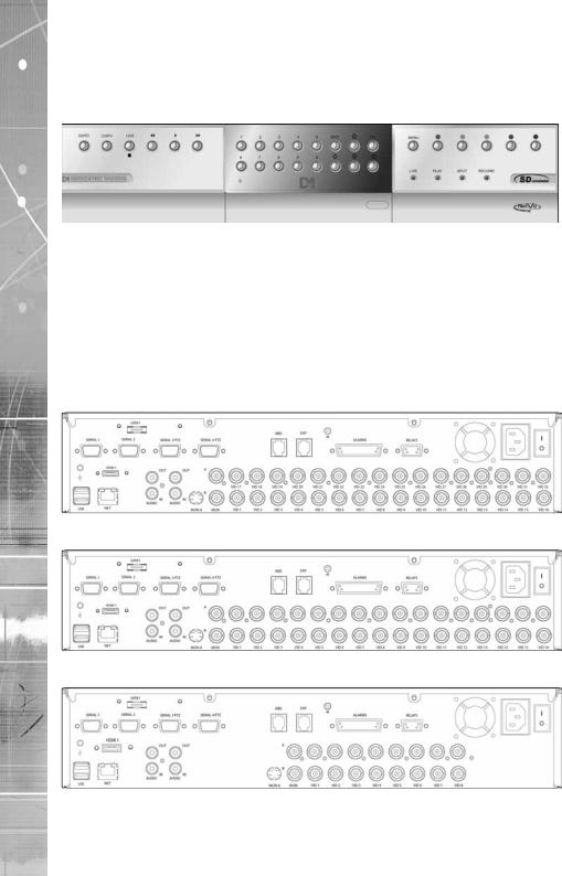
Rear Panel connections
32 Input model
16 Input model
8 Input model
10 |
Dedicated Micros ©2010 |
Video
8. 16 & 32 way units |
|
VID1 to VID8/VID16/VID32 |
75Ω BNC composite video input, 1V pk-pk with loop through 1V |
|
available on 8 and 16 input variants |
MON A |
75Ω BNC composite monitor output, 1V pk-pk |
MON B |
Spot Monitor output |
MON A |
S Video Connection |
HDMI |
High-Definition Multimedia Interface connector |
Note: The position of the HDMI connector will vary dependant on model |
|
Audio |
|
Audio IN (Dual) |
RCA (phono) socket, 8KHz/16KHz/22KHz sampling 75Ω input |
|
impedance, 1V pk-pk |
Audio OUT (Dual) |
RCA (phono) socket, line level <100Ω output impedance,1V pk- |
|
pk amplification required |
Data |
|
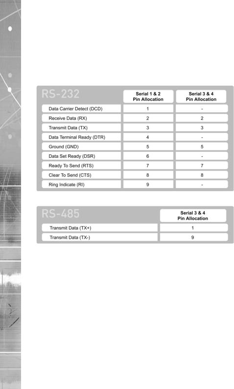
SERIAL 1 |
RS-232 (3 wire & 9 wire) |
SERIAL 2 |
RS-232 (3 wire & 9 wire) |
SERIAL 3 (PTZ) |
RS-485 (2 wire & 4 wire) |
SERIAL 4 (PTZ) |
RS-485 (2 wire & 4 wire) |
USB |
2x USB2.0 connectors |
IR |
Infra-Red Input connector for IR Remote Control Extender |
NET |
RJ45 Ethernet network connector, 10/100 Mb/s Ethernet Network |
KBD |
RJ12 connector for use with Dedicated Micros telemetry |
|
keyboards (KBC1, KBC2) |
EXP |
RJ12 expansion port for future use |
SATA |
E-Sata port available for storage expansion |
Alarms and relays |
|
ALARMS IN |
Via 25-way (female) D Type 24V 200mA |
|
20 general alarm inputs |
|
Range of Alarm states are: |
|
i. 0 – 800R = Short circuit |
|
ii. 800R – 2K = closed contact |
|
iii. 2k – 12k = open contact |
|
iv. > 12K = open circuit |
RELAYS |
Via 9-way (female) D Type rated at 24V 200mA |
|
4 onboard light duty relay output (500mA@ 12V-48V Max) |
Power |
|
POWER |
IEC mains power socket & switch |
SD Advanced
Dedicated Micros ©2010 |
11 |
SD Advanced
Installing the SD Advanced Unit
This procedure shows the sixteen camera input version.
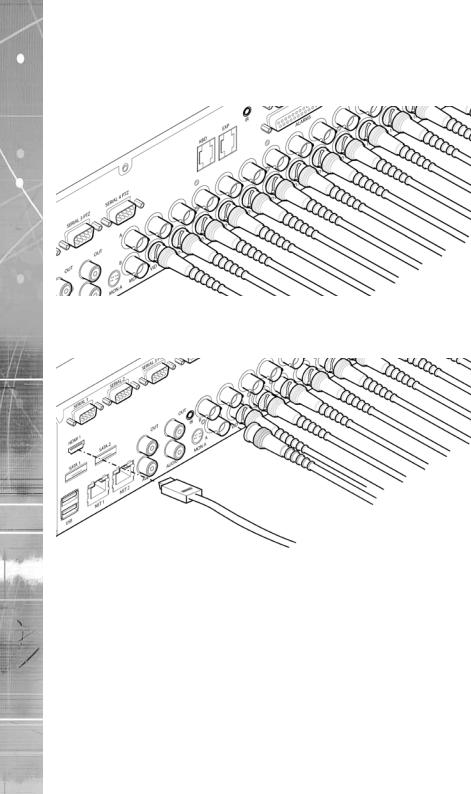
Step 1 Connecting Analog Video
The SD Advanced supports up to 8, 16 or 32 connected analog Video Inputs (dependant on model) via the 75Ω BNC connectors. Connect cameras to the video inputs, starting from input 1.
5.12
Step 2 Monitor
The unit supports a main monitor via ‘HDMI 1’ and BNC ‘A’. A spot monitor can be connected via BNC ‘B’.
Note: The position of the HDMI port will differ dependant on model.
12 |
Dedicated Micros ©2010 |

Step 3 Connecting Audio
The SD Advanced supports two channels of bi-directional audio, accessible through NetVu ObserVer. Connect the audio equipment to the phono sockets AUDIO IN and AUDIO OUT. The audio channel defaults to recording camera 1.
The following modes of operation are supported:
•Challenge – intruders from an RVRC.
•Listen – to local audio from a site at the RVRC.
•Record - local audio from a site with the video.
•Replay - all audio through a local Audio output (not supported when Audio out is used as a challenge/PA source).
Note: The Audio output can be configured as a challenge output or as a replay output.
Step 4 Connecting to the Network
The unit supports a 10/100Mbps auto-detecting network port. Use a CAT5 cable to connect the unit to the network.
By default the unit is configured for DHCP i.e. the unit is automatically allocated an IP address from a network DHCP server.
SD Advanced
Dedicated Micros ©2010 |
13 |
SD Advanced
DHCP works by assigning an IP address at initial connection to the network. It is possible however that this IP address can change without notification i.e. following power failure. It is therefore recommended that the unit be allocated a fixed IP address. A fixed IP address can be assigned via the Configuration Menu pages:Network Settings->Network->IP Address.
When the unit is powered up, the network address can be found by viewing on a local monitor and navigating to Configuration Menu pages:System Settings->System->IP Address.
Refer to ‘Configuring The Unit’ for further guidance on locating the unit’s IP address and for details of the default DNS (Domain Name Server) address.
DNS (Dynamic Name Servers) is supported and therefore the unit can be assigned a name. This removes the need for the unit to have a fixed IP address and makes it easier for a remote user to locate.
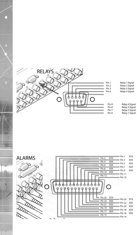
Step 5 Relays
The SD Advanced supports up to four 24V 200mA relays.
Relay Connector |
|
Pins |
Connection |
1 & 6 |
Relay 1 signal |
2 & 7 |
Relay 2 signal |
3 & 8 |
Relay 3 signal |
4 & 9 |
Relay 4 signal |
Step 6 Alarms
14 |
Dedicated Micros ©2010 |
The SD Advanced supports 20 normally open/closed tamper proof alarm inputs, or one Global keyswitch input with camera specific inputs configurable as entry/exit alarms. The alarms support tamper proof detection using 1k in line and 5K end of line resistance. The unit detects short circuit, open circuit and contact closure. This functionality is part of the advanced alarms supported on NetVu Connected products and includes features required for Central Monitoring. It is compatible with the British Standard BS8418.
Relay Connector |
|
Pin |
Alarm Input Connection |
1 - 20 |
1-20 |
21-25 |
Earth Common |
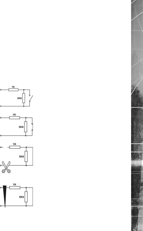
End Of Line Circuitry
The following describes the EOL tamper alarms circuitry needed when EOL has been configured. There should be two resistive values within the tamper alarm circuitry. These must be located inside the alarm device (furthest point from the unit).
The alarm state could be Normally Open or Normally closed however the tamper states are the same for both settings.
Open, the resistive value is 6.8K ohms (1K + 5.6K).
Closed, the resistive value is 1K ohms, as the circuit does not see the 5.6K ohm resistor.
Open Circuit Tamper, the resistive value is infinity as the circuit has been cut and therefore is ‘open’.
Short Circuit Tamper, the resistive value is 0 Ohms.
SD Advanced
Dedicated Micros ©2010 |
15 |
SD Advanced
Step 7 Connecting Serial Ports
Serial ports have three main uses:
1.Connecting twisted pair telemetry for PTZ cameras.
2.Providing text data recorded with the video e.g. Point of Sale.
3.Debug operations.
Note: Telemetry cameras should be connected to Serial 3 and 4. Text data can be retrieved from any serial port.
RS232
RS485
5.16
6.1
Step 8 Connecting a Keyboard
The SD Advanced supports Dedicated Micro keyboards DM/KBC1 and DM/KBC2. Connect either of these keyboards via the KBD connector on the rear panel.
Note: Refer to the Unit Operation section of this manual for further guidance regarding the supported keyboards.
16 |
Dedicated Micros ©2010 |

Step 9 Connecting DM Oracle, 2060 & 2040 Domes
A DM Oracle, 2040 or 2060 Dome can be connected via either co-axial telemetry or RS485 twisted pair. If using co-axial the address switches should be set as:
Blue switch - F Yellow switch - D
If the dome is being connected using RS485, the dome address should be set according to the camera number of the SD Advanced.
Pin connections for RS485 connection to a Dennard dome on serial port 3/4 are:
Dome Cable |
SD Advanced Serial Connector |
|
Yellow |
1 |
TX+ |
Green |
9 |
TX- |
Step 10 Connecting Power
The SD Advanced has an internal power supply unit. Connect the mains lead to the unit and then to the wall socket, or to a fused spur connection. To be compliant with wiring regulations in some countries, an Alarm/Security device should be connected to a fused spur and not a wall outlet socket (check local regulations before installation).
SD Advanced
Dedicated Micros ©2010 |
17 |

SD Advanced
Configuring the Unit
The unit can be configured either on the local monitor or over the network using a PC with Internet Explorer or similar browser. Both have near identical menu interfaces.
Accessing the menus on a local monitor
The Configuration pages can be displayed on a local monitor.
When connected, press the MENU button on the IR Remote Control.
Note: If the IR Remote Control does not open the configuration menus, press the DVR button to make sure it is in DVR mode, then press the MENU button again.
Accessing the menus on a PC web browser
Locating the Unit IP address
The IP address of the unit is required to access the webpages. It can be identified from the configuration menu pages using the local monitor, press the MENU button on the IR Remote Control and navigate to the System Settings->System menu to find the DHCP assigned IP address.
Note: The unit can be installed in a DHCP network environment where an IP address, subnet mask and default gateway will automatically be allocated from the network DHCP Server (DHCP is enabled by default).
Note: If a DNS (Domain Name Server) address is not to be used, it is strongly advised that a fixed IP address be assigned (a DHCP assigned address can change without notification i.e. following power failure).
A fixed IP address can be assigned via the Network Settings->Network menu.
For information on locating the unit’s IP address via a PC and serial port connection, refer to Appendix D.
Default DNS Address
It is recommended that a DNS (Domain Name Server) address be configured. Assigning a recognisable name can help a remote user to locate the unit.
If no System name is allocated to the unit, the default DNS address will be:
machine serial number.yourdomain.com
• |
<machine serial number> |
is displayed in the System menu |
|
|
page and also on the underside of |
|
|
the unit. |
• |
<yourdomain> |
is the name assigned to your |
|
|
DNS network. |
The default DNS address can be renamed via the Network Settings->Network menu. Following renaming, the DNS address will be:
yourname.yourdomain.com
• ’ yourname‘ |
is the name assigned via the Network menu. |
Note: To activate an assigned DNS address, it will be necessary to reboot the unit. The unit can be rebooted via System Settings:Maintain-> Reset.
IMPORTANT: To set the time and date on the unit, navigate to System Settings->Time and Date.
6.11
18 |
Dedicated Micros ©2010 |

Accessing the Configuration Webpages
The unit can be configured using the webpages. To access these:
1.Launch Internet Explorer (or similar web browser package).
2.Type the URL for the unit (IP or DNS address).
3.The Opening menu page will be displayed.
SD Advanced
Dedicated Micros ©2010 |
19 |
SD Advanced
Remote Control
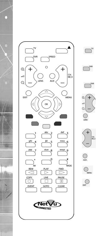
The IR Remote Control offers all the control functionality required to navigate the menus. Note: Not all buttons on the IR Remote Control are relevant for the Unit.
Key Button
Switches the Remote Control to ‘TV’ mode and sends codes understood by common TV sets.
Switches the Remote Control to ‘DVR’ mode. Note the DVR mode is the default mode of operation.
Toggle the speed of PTZ camera movement (two speeds available).
Use the Zoom button to zoom in/out with a selected camera. Also used to zoom (x2) into Live or Playback images.
This button will change the Zoom Keys operation to focus or iris functions (when available).
Use this button to cycle through available cameras.
This button should be pressed (followed by a numeric entry) to carry out auxiliary actions on a PTZ camera.
Press the Menu button to enter the
Configuration menus.
Press the Exit button to exit the
Configuration menus.
20 |
Dedicated Micros ©2010 |
Use the Directional and OK buttons to navigate through the
menu screens and accept changes. Also use for PTZ telemetry control of cameras.
Use the Softkeys (Red, Green, Yellow, Purple) to directly access the corresponding function displayed on the menu screen.
The Number pad should be used to select specific cameras and preset positions when available.
Use the Playback buttons to interrogate recorded images. Use the LIVE button to switch from Playback or menus to a LIVE display.
SD Advanced
Dedicated Micros ©2010 |
21 |

SD Advanced
Main Menu
When first accessing the unit, the main menu will be displayed. This menu allows access to the Configuration menus, the Viewer menus and also several Download options.
Note: The Download options will only be available if viewing remotely via an IP connection.
Select the Configuration menu tab to access the unit’s Configuration menus. Refer to ‘Navigating the Configuration Menus’ for further guidance.
Select the Event Search tab to access the unit’s Event Search function. Refer to ‘Event Search’ for further guidance.
Note: The ‘Event Search’ option will only be displayed if ‘Enable Event Search’ is selected in the ‘Features’ menu: System Settings->Features.
Select the Viewer menu tab to access the unit’s Viewer function. Refer to ‘Unit Operation’ for information on the numerous Viewer features.
Select the Download menu tab to access the various Download sub-options. Select from:
• |
Product Manual |
Select to open an electronic version of the |
|
|
Installation & Operation Guide. |
• |
ObserVer Manual |
Select to open an electronic version of the NetVu ObserVer |
|
|
User Guide. NetVu ObserVer is a free video management |
|
|
software package from Dedicated Micros that allows users to |
|
|
seamlessly view distributed images from any |
|
|
‘NetVu Connected’ product. |
• |
NetVu ObserVer |
Select to download the NetVu ObserVer video |
|
|
management software. |
• |
Java (JRE) |
Select to download the Java (JRE) software (from the unit). |
|
|
This software is required to successfully view Configuration |
|
|
and Viewer menus remotely. |
IMPORTANT: By default, no Usernames and Passwords are required to access any of the various menus. Usernames and Passwords can however be added to regulate access to the Configuration and Viewer menus. Refer to the ‘Console Settings-> User Accounts’ menu for information on establishing Usernames and Passwords.
22 |
Dedicated Micros ©2010 |

Navigating The Configuration Menus
When accessing the configuration menus, the menu tree will be displayed.
The configuration pages are navigated using the menu tree (displayed on the left of each page). Selecting one of the menu options will display the relevant page. Associated sub-menus will then be available.
Relevant menus can also be accessed directly from other menu screens via the coloured softkey options shown at the base of each menu. The options available will depend on the menu being viewed. Select a softkey option by pressing either the corresponding button on the IR Remote Control (if viewing the menus locally), or by selecting the relevant option via the PC mouse (if viewing the webpages).
Note: Any changes made via the webpages are automatically saved when the page is closed. To ‘manually’ save changes, select the Save option.
SD Advanced
Dedicated Micros ©2010 |
23 |

SD Advanced
Using the IR Remote Control
Press the MENU button to access configuration menus via a connected local monitor. The menu will have a red indicator highlighting the first option. Select a main menu heading to open a drop down list of further sub-options. Press the Down Directional button to highlight the next menu option, press OK to open the highlighted menu.
Press the Right Directional button to highlight the first editable parameter on the screen. Use the Left/Right/Up/Down Directional buttons to move between fields.
Select OK to start editing a field (the option will be outlined in green).
Use the Up/Down Directional buttons to change the settings within an editable field.
Use the OK button to accept a new setting. Use the coloured softkeys to select the accompanying colour option on screen i.e. red button to select the red option. To undo changes made to any menu, select the Refresh (Purple) option.
Note: See below for information on entering alpha-numeric data.
Using the Front Panel Interface
The Configuration and Viewer menus can be navigated and edited using the unit’s front panel interface (via a connected local monitor).
Navigate the menu tree via the Up/Down Directional buttons. When a menu is highlighted, open by pressing the OK button.
Use the Left/Right/Up/Down Directional buttons to move between fields. Select OK to start editing a field.
Use the Up/Down Directional buttons to change the settings within an editable field. Use the OK button to accept a new setting.
Use the Exit button to leave the Configuration pages and open the Viewer menu.
Use the colour bar buttons (Red, Green, Yellow, Blue and Purple) to directly access the corresponding function displayed on the menu screen i.e. red button to select the red option.
When viewing recorded images, use the Playback buttons (Play, Stop, Fast Forward and Rewind) to navigate the images.
Use the Goto button to display the Goto menu. This menu can be used to display recorded images from a specific date/time. Refer to Unit Operation->GoTo Menu for further information.
Use the Copy button to display the Copy menu. This menu can be used to copy recorded images to a connected USB device or disc. Refer to Unit Operation->Copy Menu for further information.
Use the Live button to switch to display live images from a camera when viewing recorded images from the same camera.
Use the Menu button to display the configuration menus.
Note: See below for information on entering alpha-numeric data.
24 |
Dedicated Micros ©2010 |

Entering Alpha-Numeric Data via a Local Monitor
Numeric or text data is entered using the on-screen Virtual Keyboard (Arrow Key Editor).
To display the Virtual Keyboard, navigate to the relevant text input box using the Directional buttons and double press the OK button twice on the IR Remote Control or Front Panel Interface. The Virtual Keyboard is displayed.
Use the Directional buttons to move between characters, use the OK button to select a character. Select ‘Submit’ to enter details, press ‘Cancel’ to exit without entering any text.
Alpha-numeric data can also be entered in either upper or lower case format by ‘multi-tapping’ a relevant button. For example, with the cursor located in the text entry window of the Virtual Keyboard, repeatedly tap button ‘2’ to cycle through the following characters: 2,A,a,B,b,C,c,2 etc.
To select one of these characters, simply stop tapping the button when the chosen character is displayed. The cursor will then progress, ready for the next character entry.
Note: A USB Keyboard (not supplied) can be connected via one of the USB ports on the unit. The USB Keyboard can then be used to enter alpha-numeric data via the local menus.
Using a USB Mouse or the Webpages
Navigate the menus by clicking the tabs displayed on the left of the menu headings (on the menu tree). The first option is highlighted with a red tab. Select a main menu heading to open a drop down list of further sub-options.
Highlight an editable field by clicking on it directly.
If viewing pages locally, enter alpha numeric data via the Arrow Key Editor (see above). If viewing remotely, enter via the PC keyboard. If available, click on the drop down menus to select settings.
Note: A selected item in the drop down list will appear highlighted.
Navigating away from a page (clicking on a different option on the menu tree) will automatically save any changed settings. To undo changes made to any menu, select the Refresh (Purple) option.
Using a Supported Dedicated Micros Keyboards (DM/KBC1 & DM/KBC2)
The unit can also be controlled using an optional Dedicated Micros keyboard. This is connected via the KBD connector on the rear of the unit and provides the same control functions as the I.R Remote Control.
Note: Refer to ‘Using the optional Keyboards (DM/KBC1 & DM/KBC2)’ for further guidance.
SD Advanced
Dedicated Micros ©2010 |
25 |

SD Advanced
System Settings
The menus under the System Settings heading allow the unit’s core settings to be viewed, changed and the system software upgraded.
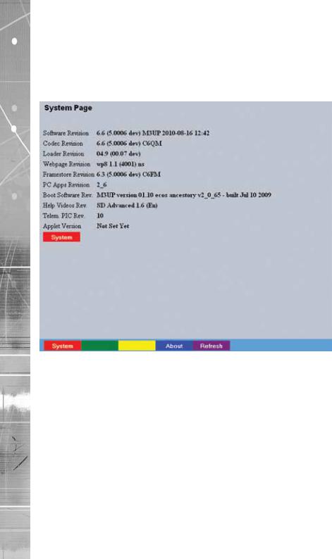
The System option displays details about the unit including the IP address, unit serial number, MAC address and software version.
The Unit Status page displays information about the unit’s operating condition, shows how long the unit has been operating and the reason for the last reset. It also shows camera status and displays any failed cameras.
The Alarm Status page shows which contacts are open, which zones are in alarm and which relays are operating.
The Language page allows the system language to be set. The language can also be changed for the current session only.
The Time and Date page allows the unit time and date settings to be adjusted, including setting the timezone.
The Serial Ports page allows each of the four serial ports to be individually configured for one of a range of operations, including EPOS, debug, PPP and telemetry.
The Audio page shows the settings available for each of the audio channels and allows configuration of audio quality.
The Features page allows control of the different features that are available within the software including Email reporting, webcam support and control of the display resolution.
The Maintain page allows the current configuration to be saved, and for previously saved settings to be loaded. It also enables easy upgrade of the system software.
The PowerScript Mgmt page allows installed PowerScripts to be activated/deactivated on start-up. The About menu allows access to numerous system information pages.
26 |
Dedicated Micros ©2010 |

System
This menu shows the general information about the unit including the version of software installed, the unit’s serial number and the allocated DHCP IP address.
Product Descriptor |
Details the product model. |
Serial Number |
Identifies the serial number of the specific unit. |
PCB Serial Number |
Displays the PCB (Printed Circuit Board) serial number of the unit. |
Product Code |
Displays a code identifying the unit’s specification. |
Earliest Recording |
Displays the date/time of the earliest recording held on the unit. |
System Name |
This field can be edited to allocate a name to the unit. This is |
|
displayed when the unit is accessed via NetVu ObserVer and is |
|
sent when transmitting information to a Remote Video Response |
|
Centres (RVRC). |
Video Standard |
Displays the video standard adopted by the unit i.e. PAL, NTSC. |
Number of Cameras |
Shows the number of camera channels on the unit. |
Global PPS |
Details the Global PPS (Pictures Per Second) recording rate for |
|
all cameras at 4CIF, 2CIF and CIF. |
Video Storage Gbytes |
Highlights the available video storage capacity in Gigabytes. |
MAC Address |
This is the MAC address assigned to the unit. |
IP Address |
This is the IP address allocated to the unit. |
SD Advanced
Dedicated Micros ©2010 |
27 |
SD Advanced
Sub Net |
This is the subnet of the network where the unit is located. |
Gateway |
This is the IP address of the default gateway (router) assigned by |
|
the DHCP server. |
Software (Red) |
Select this option to display installed software information |
|
(see below). |
Software Menu
Software Revision |
This identifies the version of software the unit is running. |
|
Codec Revision |
This identifies the codec version the unit is running. |
|
Webpage Revision |
This identifies the webpage version the unit is running. |
|
Framestore Revision |
This identifies the Framestore Revision the unit is running. |
|
PC Apps Revision |
This identifies the revision archive of the Viewer and associated |
|
|
|
PC Apps software. |
Boot Software Rev. |
Displays the infrastructure componentry software revision. |
|
Help Videos Rev. |
This identifies the version of Help Videos installed on the unit. |
|
Note: |
Refer to ‘Go To Viewer->Help Videos’ for guidance on viewing the imbedded Help Videos. |
|
Telem PIC Rev. |
This identifies the version of the Telemetry control device installed |
|
|
|
on the unit. |
Applet Version |
This identifies the applet version installed on the unit |
|
Note: |
Refer to ‘Display Settings->Viewer Defaults’ for guidance on using a remote applet (this can |
|
|
lessen load times when accessing multiple DVRs/Servers). |
|
System (Red) |
Select this option to return to the System menu. |
|
28 |
Dedicated Micros ©2010 |
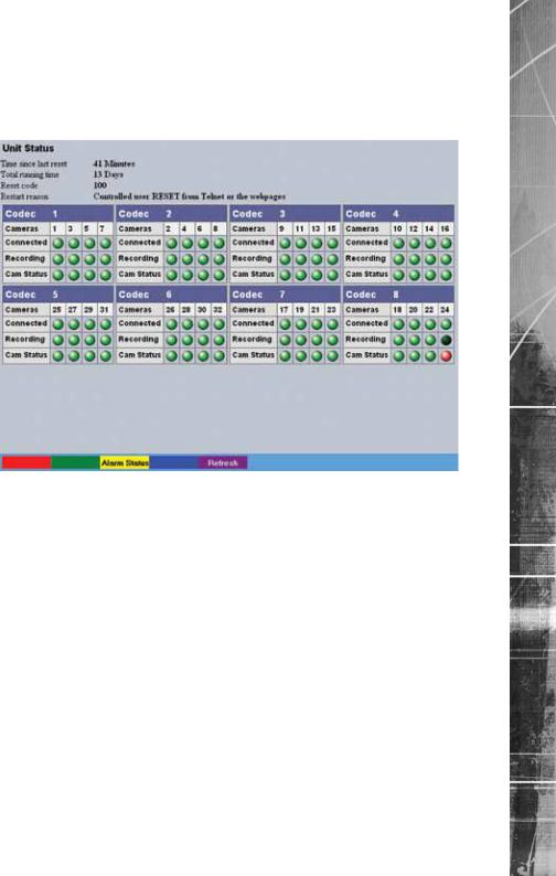
Unit Status
This menu details information regarding the status of the unit, notably the total time the unit has been operating and the time since its last reset. Status log information can also be exported via the ‘Export Logs’ option to either a CD-R/DVD-R or a USB device.
Time since last reset |
Details the time since the unit was last reset. |
Total running time |
Details the total time the unit has been operational. |
Reset code |
The last reset code used is displayed. |
Restart reason |
The reason for the last restart is displayed i.e. Controlled |
|
User Reset. |
Codec |
Up to four codecs are installed within the unit (dependant on |
|
model). Cameras are assigned to the codec in the following |
|
sequence: Camera 1 is assigned to Codec 1, Camera 2 to Codec |
|
2, Camera 3 to Codec 3, Camera 4 to Codec 4, Camera 5 to |
|
Codec 1, Camera 6 to Codec 2, etc. |
|
Within each Codec window, each camera channel is listed, along |
|
with connection, recording and camera status information. |
Cameras |
Cameras assigned to each codec are displayed.. |
Connected |
Those camera channels with cameras connected will be |
|
highlighted light green. Those not in use will appear dark green. |
Recording |
Those camera channels that are currently recording are |
|
highlighted light green. Those not recording will appear |
|
dark green. |
Cam Status |
Those camera channels where the connection is deemed to |
|
be functioning correctly will be highlighted light green. Those |
|
deemed to have failed will appear red. Camera channels with no |
|
connected camera will appear dark green. |
SD Advanced
Dedicated Micros ©2010 |
29 |

SD Advanced
Alarm Status
This menu details information regarding the status of the unit’s alarm contacts, alarm zones and relay outputs.
Alarm Contacts/Zones/Relay Outputs Alarm Contacts, Alarm Zones and Relay Outputs that are in an ‘active’ state are shown light green. ‘In-active’ ones appear dark green (not illuminated).
30 |
Dedicated Micros ©2010 |
 Loading...