

Page 1

Installation Guide
Page 2

2
SD Excel
Whilst every attempt is made to ensure these manuals are accurate and current, Dedicated Micros reserve the right to alter or
modify the specication of the machine described herein without prejudice.
Features ........................................................................................... 4
Important Safeguards ....................................................................... 6
Installing the Unit .............................................................................. 8
Installation ...................................................................................... 10
Conguring the Unit ........................................................................ 18
Remote Control .............................................................................. 20
Main Menu ...................................................................................... 22
Navigating The Conguration Menus ............................................. 24
System Settings ............................................................................. 27
Display Settings .............................................................................. 53
Camera Settings ............................................................................. 64
Record Settings .............................................................................. 75
Schedule ........................................................................................ 86
Alarm Settings ...................................................................................... 89
Network Settings .......................................................................... 108
Features & Text ............................................................................ 124
Analytics & Third Party IP Cameras ............................................. 125
Installing An Advanced Feature License .......................................... 126
Archive ......................................................................................... 145
Oracle Dome Conguration .......................................................... 147
Unit Operation .............................................................................. 161
Operating the Viewer .................................................................... 162
Using the Optional Keyboards ...................................................... 185
Appendix A - Pinouts .................................................................... 189
Appendix B- Remote Control Codes ............................................ 190
Appendix C - User Activity Logging .............................................. 192
Appendix D -
Locate IP Address (Serial)
...................................... 193
Appendix E - Videolan VLC .......................................................... 194
Appendix F - Third Part IP Camera .............................................. 195
Appendix G - Monitor Output ........................................................ 196
Appendix I - Unit Specication ..................................................... 197
Appendix H - Status Pages .......................................................... 199
Contents
Page 3

3
Installation Guide
Introduction
What is the…
SD Excel ?
The agship product in the SD Series, the SD Excel offers real-time, 4CIF/D1 recording per camera in a
premium enterprise hybrid DVR/NVR package that combines all the benets of a DVR with the feature set
of a high performance embedded NVR and offers multiple channels of IP and Analogue video, HDMI main
monitor support, on-board analytics, help videos and Oracle Dome conguration.
Powerful Hybrid DVR/NVR
The SD Excel is a true hybrid DVR/NVR. Offering up to 32 camera connections in a combination of
analogue or IP (including 3rd party IP cameras). Up to 16 analogue cameras can be connected, with the
balance of the 32 camera channels being made up by IP camera streams - even HD cameras.
REAL-TIME, 4CIF/D1 RECORDING PER CAMERA
Offering a blend of analogue and IP connections. Each camera can offer 4CIF/D1, real-time viewing,
recording and playback simultaneously.
PERFORMANCE BOOST WITH TURBO MODE
The latest generation SD Excel includes powerful new codecs and the Turbo Mode feature that ensures
maximum per camera performance. Enabling Turbo Mode can effectively double the units performance
allowing real-time recording at double the resolution simply with the press of a button.
For further information, please visit the website:
www.dedicatedmicros.com
or contact customer services in your region.
from Software version 6.6 (8.0052) M3UP
Page 4

4
SD Excel
Features
• 16 analog camera input options
• Telemetry support (Coax & Serial)
• All DVR functions fully supported by Keyboard/IR Remote Control/Front Panel
• Scalable recording settings
• MultiMode Recording - Dynamically-switchable resolution, record-rate & compression
(MPEG4/JPEG) per camera
• JPEG or MPEG-4 recording and transmission
• Up to 4TB of on-board storage
• HDMI monitor support
• I.P Camera support
• Web pages provide easy remote conguration
• Single, Picture in Picture and Multiway displays
• Live and playback viewing locally and over Ethernet
• Built in activity detection
• On-board Help videos
• Built in CD-R/DVD-R writer and USB ports for download of video archive to external
ash memory
• Point&go telemetry control and Absolute Positioning
• Alarm Inputs & Outputs
• Easy to use on-screen, colour coded soft keys
• Front panel interface
• Text support and text search features ideal for retail installations
• Optional external keyboard available
• Conguration via USB mouse and USB QWERTY keyboard
• BS8418 compliant
The unit has NetVu Connected technology built-in to ensure maximum compatibility with future
developments in networked security. NetVu Connected technology enables the Unit to fully interact with
other NetVu Connected compatible products from Dedicated Micros including the DV-IP Decoder, NetVu
ObserVer and PDA Viewers. Providing interoperability between the worlds leading security companies,
NetVu Connected uses industry standard networking protocols supported by a wide range of third party
integration products and SDKs to ensure future on-going compatibility.
COMMON CONFIGURATION INTERFACE
A Common Conguration interface is displayed when the unit’s conguration screens are accessed locally
at the unit or remotely via a web browser. This unied system ensures that the installer is familiar with the
conguration screens irrespective of their location to the unit, minimising training and familiarisation time
and increasing the speed of installation and alteration.
Page 5

5
Installation Guide
The Unit includes a unique colour-coded menu structure and on screen Graphical User Interface (GUI).
Context sensitive, the menu structure always represents the area of the menu the user is in, allowing
them to quickly select the options and settings they need without having to trawl through menu pages and
options. The colour coded buttons displayed on the monitor match those on the IR Remote Control, whilst
control can also be conducted through an attached USB Mouse or supported Keyboard (DM/KBC1 / DM/
KBC2).
Point&go provides the user with easy to use, fast, accurate telemetry control via an attached monitor.
With no need for a telemetry keyboard, users are able to use Pan & Tilt control of a Dedicated Micros
Oracle Dome simply by clicking an area of the monitor. The camera will instantly respond, positioning the
selected area in the middle of the screen, ideal for tracking movement through a scene.
MAP
Users can now navigate around their CCTV installation using a graphical map. Selecting the relevant
camera from the map will instantly connect the user to that cameras image stream. With the ability to
load bespoke map images and oor plans to reect their installations, the Maps feature is ideal for quickly
identifying camera locations around a site or CCTV network.
Turbo Mode
Turbo mode allows video images from any analogue camera or 3rd Party IP recoded camera to be
recorded and streamed at the maximum possible rate without the need to congure individual settings.
Turbo mode must be set Globally and will result in MPEG record rates of 25pps@4CIF/2CIF/CIF/QCIF.
Design of the manual
The manual has three parts:
1. Installation Shows details of how to install the unit and connect external devices.
2. Conguration Shows details of the unit’s menus.
3. Operation Shows quick reference details on how to control the unit.
The order and layout of these pages has been designed to help the setup process. It is recommended
that the menus are edited sequentially (as they appear on the page), to enable accurate, easy and
efcient setup.
Page 6

6
SD Excel
Important Safeguards
Read Instructions
All the safety and operating instructions should be read before the unit is operated.
Power Sources
This unit should be operated only from the type of power source indicated on the manufacturer’s label.
Servicing
Do not attempt to service this unit yourself as opening or removing covers may expose you to dangerous
voltage or other hazards.
Refer all servicing to qualied service personnel.
Ventilation
Ensure unit is properly ventilated to protect from overheating.
All the safety and operating instructions should be read before the unit is operated.
To prevent re or shock hazard, do not expose this equipment to rain or moisture. The lightning ash with
arrowhead symbol within an equilateral triangle is intended to alert the user of this equipment that there
are dangerous voltages within the enclosure which may be of sufcient magnitude to constitute a risk of
electric shock.
This is a class A product. In a domestic environment this product may cause radio interference in which
case the user may be required to take adequate measures.
Lightning Strike
The unit has some inbuilt protection for lightning strike, however it is recommended that isolation
transformers be tted to the system in areas where lightning is a common occurrence.
Regulatory Notes and FCC and DOC Information
(USA and Canadian Models Only)
Warning: This equipment has been tested and found to comply with the limits for a Class A digital device,
pursuant to part 15 of the FCC rules. These limits are designed to provide reasonable protection against
harmful interference when the equipment is operated in a commercial environment. This equipment
generates, uses, and can radiate radio frequency energy and, if not installed and used in accordance
with the instruction manual, may cause harmful interference to radio communications. Operation of this
equipment in a residential area is likely to cause harmful interference in which case the user will be
required to correct the interference at their own expense.
If necessary, the user should consult the dealer or an experienced radio/television technician for
corrective action. The user may nd the following booklet prepared by the Federal Communications
Commission helpful: “How to Identify and Resolve Radio-TV Interference Problems”.
This booklet is available from the US Government Printing Ofce, Washington, DC20402,
Stock No. 004-000-00345-4.
This reminder is provided to call the CCTV system installer’s attention to Art. 820-40 of the NEC that
provides guidelines for proper grounding and, in particular, species that the cable ground shall be
connected to the grounding system of the building, as close to the point of cable entry as practical.
Page 7

7
Installation Guide
CE Mark
If this product is marked with the CE symbol it indicates compliance with all applicable directives.
Directive 89/336/EEC.
A ‘Declaration of Conformity’ is held at Dedicated Micros Ltd.,
1200 Daresbury Park, Daresbury, Cheshire, WA4 4HS, UK.
Laser
The unit supports an integrated CD-R/DVD-R writer, the following are additional warnings associated with
installing and operating the CD-R/DVD-R writer, please pay particular attention to this information.
• Caution - Use of controls or adjustments or performance of procedures other than those
specied herein may result in hazardous radiation exposure.
• To prevent exposure to laser emanations (harmful to the eyes), do not attempt to
disassemble this unit.
Page 8

8
SD Excel
Installing the Unit
Before you start
Check the contents of the box
The following items are included in the box:
Remove all items from the packaging and check the items listed below are present.
• SD Excel NVR (16 input)
• IR Remote Control
• Power Leads
• IR Extender Lead
• SD Excel Software/Documentation CD
• Mouse
• Rack Mounting brackets
• RS485 Telemetry Adaptor
• Quick Start Guide
If any of these items are missing please contact Dedicated Micros Technical Support team.
Note: Before installing the SD Excel DVR, carefully read all Safety Instructions and the following
information on where the unit should be located.
Choosing a location for installation
• The SD Excel is designed to be desk, shelf or rack mounted. Rack mounting brackets are
available as an optional accessory.
• Ensure the SD Excel unit is properly ventilated to protect from overheating.
• Ensure there is a 3cm gap on both sides of the unit.
• Ensure the IR receiver on the front of the unit faces the operator position, and is not more
than 10 feet (3 metres) from the operator. An IR Remote Control Extender is also available.
• Ensure the unit is not located anywhere it could be subject to mechanical shocks.
• The unit should be located in an area with low humidity and a minimum of dust. Avoid places
like damp basements or loft spaces.
• If the unit is to be installed in a closed assembly, the maximum operating temperature must
not exceed 40°C (104°F).
• Ensure there is reliable earthing of the mains outlet when tted to supply connections (other
than direct connection to the branch circuit).
• Any branch circuit supplying the unit must be rated at 15Amps.
• It is recommended that an uninteruptable power source be connected to the unit in case of
power failure (to ensure continuous operation of the unit).
Page 9

9
Installation Guide
Electrical Connections
Please ensure the following are available and have been tested prior to the installation:
• Mains point
• Network point
• Network cable
• Active video signals i.e. at least one working camera feed
• PC with CD ROM drive and connection to the same network as the NVR (Recommended).
Quick Overview of SD Excel Record Settings
The SD Excel provides as default:
Consistent recording duration and smooth motion video per camera regardless of the number of cameras.
Default record settings at MPEG4 6.25pps (at 2CIF), JPEG 3pps (at 2CIF) and MultiMode recording at
MPEG4 6.25pps (at 2CIF), JPEG 6.25pps (at 2CIF).
Complete Flexibility
The advanced record menu can be used to congure individual cameras to suit specic requirements
e.g. Entry/Exit routes. Various storage sizes are available dependent on the combination of the number of
cameras, the storage options and record rates selected.
MultiMode Recording
The unit supports MultiMode recording, which is a storage technology developed by Dedicated Micros.
This offers the ability to set different recording rates, resolutions and compression formats across
scheduled, normal and alarm modes for each individual camera.
By varying the quality, bit rate and le size of the recorded images, the MultiMode function can increase
recording capabilities of the unit.
MultiMode offers:
Ability to set different recording resolutions.
Ability to set and switch MPEG or JPEG compression recording as required.
Ability to set PPS recording rate per camera.
Dynamically switchable resolution when switching from Normal to Event recording.
Dynamically switchable compression between MPEG4 and JPEG from Normal to
Event recording.
Page 10
10
SD Excel
Installation
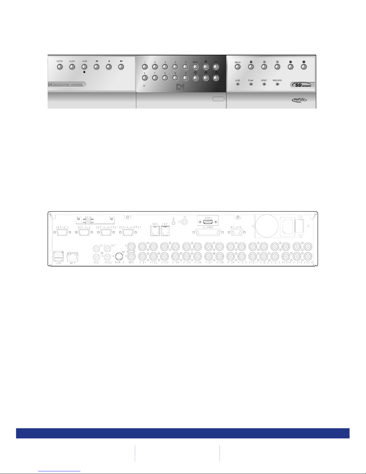
Front Panel connections
Data
DVD-R Internal CD/DVD-R drive (located under hinged ap)
USB USB2.0 connector (located under hinged ap)
LED Green - Unit working normally
No LED - Power Failure
Live - Unit is in Live mode when lit.
Play -Unit is in Playback mode when lit.
Spot - Spot (MON B) monitor is being controlled
Record - Unit is recording video to the internal hard disk.
Rear Panel connections
Video
VID1 to VID16 75Ω BNC composite video input, 1V pk-pk with loop through 1V
available on 8 and 16 input variants
MON A 75Ω BNC composite monitor output, 1V pk-pk
MON B Spot Monitor output
MON A S Video Connection
HDMI High-Denition Multimedia Interface connector
Note: The position of the HDMI connector will vary dependent on model
Audio
Audio IN (Dual) RCA (phono) socket, 8KHz/16KHz/22KHz sampling 75Ω input
impedance, 1V pk-pk
Audio OUT (Dual) RCA (phono) socket, line level <100Ω output impedance,1V pk-pk
amplication required
Page 11

11
Installation Guide
Data
SERIAL 1 RS-232 (3 wire & 9 wire)
SERIAL 2 RS-232 (3 wire & 9 wire)
SERIAL 3 (PTZ) RS-485 (2 wire & 4 wire)
SERIAL 4 (PTZ) RS-485 (2 wire & 4 wire)
USB 2x USB2.0 connectors
IR Infra-Red Input connector for IR Remote Control Extender
NET RJ45 Ethernet network connector, 10/100 Mb/s Ethernet Network
KBD RJ12 connector for use with Dedicated Micros telemetry
keyboards (KBC1, KBC2)
EXP RJ12 expansion port for future use
SATA E-Sata port available for storage expansion
Alarms and relays
ALARMS IN Via 25-way (female) D Type 24V 200mA
20 general alarm inputs
Range of Alarm states are:
i. 0 – 800R = Short circuit
ii. 800R – 2K = closed contact
iii. 2k – 12k = open contact
iv. > 12K = open circuit
RELAYS Via 9-way (female) D Type rated at 24V 200mA
4 onboard light duty relay output (500mA@ 12V-48V Max)
Power
POWER IEC mains power socket & switch
Page 12

12
SD Excel
Installing the SD Excel Unit
This procedure shows the sixteen camera input version.
Step 1 - Connecting to the Network
USB
NET 1
VID 1 VID 2 VID 3
VID 13
VID 8
VID 6VID 4 VID 5 VID 7 VID 9 VID 10 VID 12VID 11 VID 14 VID 15
POWER
IR
MON A
AUDIO
B
B
B
B
B
B
B
B
B
B
B
B
B
B
ALARMS
IR
EXP
KBD
RELAYS
HDMI
B
VID 16
B
AUDIO
IN
OUT
OUT
A
B
SERIAL 2
SERIAL 3 PT
Z
SERIAL 1
SERIAL 4 PTZ
SATA
The unit supports a 10/100 Mbps auto-detecting network port to allow connection to a normal switch.
Step 2 - Connecting Video
1
VID 1 VID 2 VID 3
VID 13
VID 8
VID 6VID 4 VID 5 VID 7
VID 9 VID 10 VID 12VID 11 VID 14 VID 15
POWER
IR
MON A
AUDIO
B
B
B
B
B
B
B
B
B
B
B
B
B
B
ALARMS
IR
EXP
KBD
RELAYS
HDMI
B
VID 16
B
AUDIO
IN
OUT
OUT
A
B
SERIAL 2
SERIAL 3 PTZ
SERIAL 1
SERIAL 4 PTZ
SATA
The SD Excel supports up to 16 connected analog Video Inputs (dependent on model) via the 75Ω BNC
connectors. Connect cameras to the video inputs, starting from input 1.
5.12
Page 13

13
Installation Guide
Step 3 - Monitor
VID 13
VID 8
VID 6
VID 7 VID 9 VID 10 VID 12VID 11 VID 14 VID 15
POWER
B
B
B
B
B
B
B
B
B
B
ALARMS
IR
EXP
KBD
RELAYS
HDMI
B
VID 16
B
The unit supports a main monitor via ‘HDMI 1’ and BNC ‘A’. A spot monitor can be connected via BNC ‘B’.
The unit will boot up in SAFE mode. This allows viewing on both composite and HDMI (if HDMI is
connected during BOOT UP).
Important: Safe mode is suboptimal, and an appropriate display setting should be congured in the
Viewer Defaults Conguration pages.
Step 4 - Connecting Audio
USB
NET 1
VID 1 VID 2 VID 3
VID 13
VID 8
VID 6
VID 4 VID 5
VID 7 VID 9 VID 10 VID 12VID 11 VID 14 VID 15
POWER
IR
MON A
AUDIO
B
B
B
B
B
B
B
B
B
B
B
B
B
B
ALARMS
IR
EXP
KBD
RELAYS
HDMI
B
VID 16
B
AUDIO
IN
OUT
OUT
A
B
SERIAL 2
SERIAL 3 PTZ
SERIAL 1
SERIAL 4 PTZ
SATA
The SD Excel supports two channels of bi-directional audio, accessible through NetVu ObserVer. Connect
the audio equipment to the phono sockets AUDIO IN and AUDIO OUT. The audio channel defaults to
recording camera 1.
The following modes of operation are supported:
• Challenge – intruders from an RVRC.
• Listen – to local audio from a site at the RVRC.
• Record - local audio from a site with the video.
• Replay - all audio through a local Audio output (not supported when
Audio out is used as a challenge/PA source).
Note: The Audio output can be congured as a challenge output or as a replay output.
Page 14

14
SD Excel
Step 5 - Relays
VID 13
VID 8
VID 7 VID 9 VID 10 VID 12VID 11 VID 14 VID 15
POWER
B
B
B
B
B
B
B
B
B
RELAYS
HDMI
B
VID 16
B
RELAYS
Pin 1 Relay 1 Signal
Pin 2 Relay 2 Signal
Pin 3 Relay 3 Signal
Pin 4 Relay 4 Signal
Pin 5
Pin 9
Relay 4 Signal
Pin 8
Relay 3 Signal
Pin 7
Relay 2 Signal
Pin 6
Relay 1 Signal
View on
rear of
unit
Note: HDMI shown removed.
The SD Excel supports up to four 24V 200mA relays.
Relay Connector
Pins Connection
1 & 6 Relay 1 signal
2 & 7 Relay 2 signal
3 & 8 Relay 3 signal
4 & 9 Relay 4 signal
Step 6 - Alarms
VID 13VID 6VID 4 VID 5 VID 7 VID 9 VID 15
POWER
B
B
B
B
ALARMS
IR
HDMI
VID 16
View on
rear of
unit
VID 9
V
rear of
unit
V
Pin 2 DTX
Pin 4 DTX
Pin 6 DTX
Pin 8 DTX
Pin 10 DTX
Pin 12 DTX
Pin 1 DTX
Pin 3 DTX
Pin 5 DTX
Pin 7 DTX
Pin 9 DTX
Pin 11 DTX
Pin 13 DTX
Pin 25 Earth
Pin 23 Earth
Pin 21 Earth
Pin 19 DTX
Pin 17 DTX
Pin 15 DTX
Pin 24 Earth
Pin 22 Earth
Pin 20 DTX
Pin 18 DTX
Pin 16 DTX
Pin 14 DTX
ALARMS
The SD Excel supports 20 normally open/closed tamper proof alarm inputs, or one Global keyswitch
input with camera specic inputs congurable as entry/exit alarms. The alarms support tamper proof
detection using 1k in line and 5K end of line resistance. The unit detects short circuit, open circuit and
contact closure. This functionality is part of the advanced alarms supported on NetVu Connected products
and includes features required for Central Monitoring. It is compatible with the British Standard BS8418.
Page 15

15
Installation Guide
Relay Connector
Pin Alarm Input Connection
1 - 20 1-20
21-25 Earth Common
End Of Line Circuitry
The following describes the EOL tamper alarms circuitry needed when EOL has been congured. There
should be two resistive values within the tamper alarm circuitry. These must be located inside the alarm
device (furthest point from the unit).
The alarm state could be Normally Open or Normally closed however the tamper states are the same for
both settings.
Open, the resistive value is 6.8K ohms (1K + 5.6K).
Closed, the resistive value is 1K ohms, as the circuit does not see the 5.6K ohm resistor.
Open Circuit Tamper, the resistive value is innity as the circuit has been cut and
therefore is ‘open’.
Short Circuit Tamper, the resistive value is 0 Ohms.
Page 16
16
SD Excel
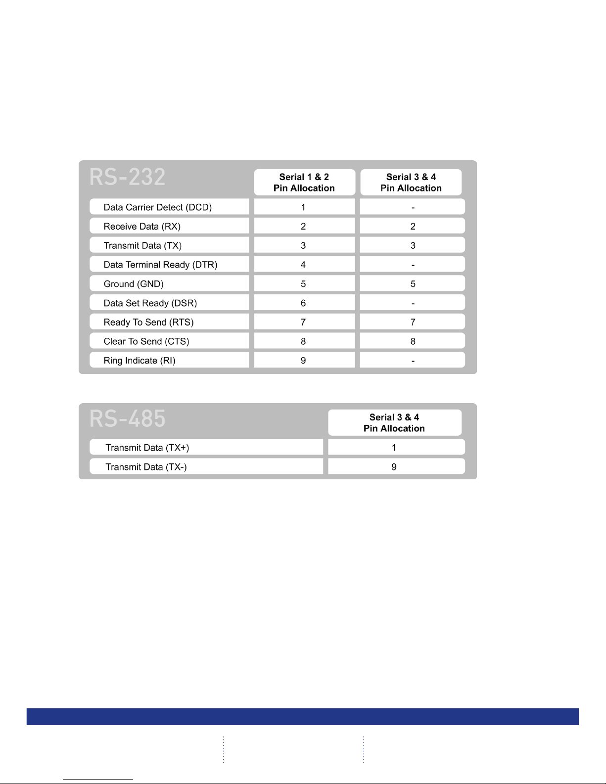
Step 7 - Connecting Serial Ports
Serial ports have three main uses:
1. Connecting twisted pair telemetry for PTZ cameras.
2. Providing text data recorded with the video e.g. Point of Sale.
3. Debug operations.
Note: Telemetry cameras should be connected to Serial 3 and 4. Text data can be retrieved from any
serial port.
RS232
RS485
6.1
Step 8 - Connecting a Keyboard
The SD Excel supports Dedicated Micro keyboards DM/KBC1 and DM/KBC2. Connect either of these
keyboards via the KBD connector on the rear panel.
Note: Refer to the Unit Operation section of this manual for further guidance regarding the supported
keyboards.
Page 17

17
Installation Guide
Step 9 - Connecting DM Oracle, 2060 & 2040 Domes
A DM Oracle, 2040 or 2060 Dome can be connected via either co-axial telemetry or RS485 twisted pair. If
using co-axial the address switches should be set as:
Blue switch - F
Yellow switch - D
If the dome is being connected using RS485, the dome address should be set according to the camera
number of the SD Excel.
Pin connections for RS485 connection to a Dennard dome on serial port 3/4 are:
Dome Cable SD Excel Serial Connector
Yellow 1 TX+
Green 9 TX-
Step 10 - Connecting Power
VID 13
VID 12
VID 14 VID 15
POWER
B
B
B
B
S
IR
RELAYS
HDMI
B
VID 16
B
The SD Excel has an internal power supply unit. Connect the mains lead to the unit and then to the wall
socket, or to a fused spur connection. To be compliant with wiring regulations in some countries, an Alarm/
Security device should be connected to a fused spur and not a wall outlet socket (check local regulations
before installation).
Page 18

18
SD Excel
Conguring the Unit
The unit can be congured either on the local monitor or over the network using a PC with Internet
Explorer or similar browser. Both have near identical menu interfaces.
Accessing the menus on a local monitor
The Conguration pages can be displayed on a local monitor.
When connected, press the MENU button on the IR Remote Control.
Note: If the IR Remote Control does not open the conguration menus, press the DVR button to make
sure it is in DVR mode, then press the MENU button again.
Accessing the menus on a PC web browser
Locating the Unit IP address
The IP address of the unit is required to access the webpages. It can be identied from the conguration
menu pages using the local monitor, press the MENU button on the IR Remote Control and navigate to
the System Settings->System menu to nd the DHCP assigned IP address.
Note: The unit can be installed in a DHCP network environment where an IP address, subnet mask and
default gateway will automatically be allocated from the network DHCP Server (DHCP is enabled
by default).
Note: If a DNS (Domain Name Server) address is not to be used, it is strongly advised that a xed IP
address be assigned (a DHCP assigned address can change without notication i.e. following
power failure).
A xed IP address can be assigned via the Network Settings->Network menu.
For information on locating the unit’s IP address via a PC and serial port connection, refer to Appendix C.
Default DNS Address
It is recommended that a DNS (Domain Name Server) address be congured. Assigning a recognisable
name can help a remote user to locate the unit.
If no System name is allocated to the unit, the default DNS address will be:
machine serial number.yourdomain.com
• <machine serial number> is displayed in the System menu
page and also on the underside of
the unit.
• <yourdomain> is the name assigned to your
DNS network.
The default DNS address can be renamed via the System->Attributes menu. Following renaming, the
DNS address will be::
yourname.yourdomain.com
• ’ yourname‘ is the name assigned via the Network menu.
Note: To activate an assigned DNS address, it will be necessary to reboot the unit. The unit can be
rebooted via System -> Maintain-> Reset.
IMPORTANT: To set the time and date on the unit, navigate to System Settings->Time and Date.
6.11
Page 19

19
Installation Guide
Accessing the Conguration Webpages
The unit can be congured using the webpages. To access these:
1. Launch Internet Explorer (or similar web browser package).
2. Type the URL for the unit (IP or DNS address).
3. The Opening menu page will be displayed.
6.13
Page 20

20
SD Excel
Remote Control
The IR Remote Control offers all the control functionality required to navigate the menus.
Note: Not all buttons on the IR Remote Control are relevant for the Unit.
Key Button
Switches the Remote Control to ‘TV’
mode and sends codes understood by
common TV sets.
Switches the Remote Control to ‘DVR’
mode. Note the DVR mode is the
default mode of operation.
Toggle the speed of PTZ camera
movement (two speeds available).
Use the Zoom button to zoom in/out
with a selected camera. Also used to
zoom (x2) into Live or Playback images.
This button will change the Zoom Keys
operation to focus or iris functions
(when available).
Use this button to cycle through
available cameras.
This button should be pressed (followed
by a numeric entry) to carry out auxiliary
actions on a PTZ camera.
Press the Menu button to enter the
Conguration menus.
Press the Exit button to exit the
Conguration menus.
Page 21
21
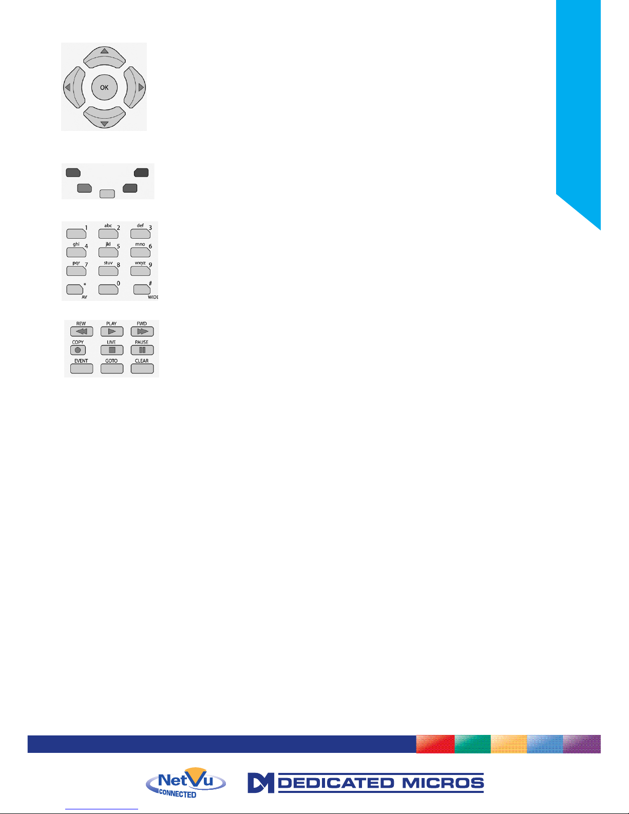
Installation Guide
Use the Directional and OK buttons to navigate through the
menu screens and accept changes. Also use for PTZ telemetry control
of cameras.
Use the Softkeys (Red, Green, Yellow, Purple) to directly access the
corresponding function displayed on the menu screen.
The Number pad should be used to select specic cameras and preset
positions when available.
Use the Playback buttons to interrogate recorded images. Use the LIVE
button to switch from Playback or menus to a LIVE display.
Page 22

22
SD Excel
Main Menu
When rst accessing the unit, the main menu will be displayed. This menu allows access to the
Conguration menus, the Viewer menus and also several Download options.
Note: The Download options will only be available if viewing remotely via an IP connection.
Select the Conguration menu tab to access the unit’s Conguration menus, refer to ‘Navigating the
Conguration Menus’ for further guidance.
Select the Event Search tab to access the unit’s Event Search function, refer to ‘Event Search’ for further
guidance.
Note: The ‘Event Search’ option will only be displayed if ‘Enable Event Search’ is selected in the
‘Features’ menu: System Settings->Features.
Select the Viewer menu tab to access the unit’s Viewer function, refer to ‘Unit Operation’ for information
on the numerous Viewer features.
Select the Download menu tab to access the various Download sub-options. Select from:
• Product Manual Select to open an electronic version of the Installation & Operation Guide.
• ObserVer Manual Select to open an electronic version of the NetVu ObserVer User Guide.
NetVu ObserVer is a free video management software package from
Dedicated Micros that allows users to seamlessly view distributed images
from any ‘NetVu Connected’ product.
• NetVu ObserVer Select to download the NetVu ObserVer video management software.
• Java (JRE) Select to download the Java (JRE) software (from the unit). This software
is required to successfully view Conguration and Viewer menus
remotely.
Page 23

23
Installation Guide
IMPORTANT: By default, Usernames and Passwords are NOT required to access any of the menus.
Usernames and Passwords can be added to regulate access to the Conguration and
Viewer menus, refer to the ‘Console Settings-> User Accounts’ menu for information on
establishing Usernames and Passwords.
Page 24

24
SD Excel
Navigating The Conguration Menus
The menu tree provides access to the conguration menus.
The conguration pages are navigated using the menu tree (displayed on the left of each page). Selecting
one of the menu options will display the relevant page. Associated sub-menus will then be available.
Relevant menus can also be accessed directly from other menu screens via the coloured softkey options
shown at the base of each menu. The options available will depend on the menu being viewed. Select
a softkey option by pressing either the corresponding button on the IR Remote Control (if viewing the
menus locally), or by selecting the relevant option via the PC mouse (if viewing the webpages).
Note: Any changes made via the webpages are automatically saved when the page is closed. To
‘manually’ save changes, select the Save option.
Page 25

25
Installation Guide
Using the IR Remote Control
Press the MENU button to access conguration menus via a connected local monitor. The menu will
have a red indicator highlighting the rst option. Select a main menu heading to open a drop down list of
further sub-options. Press the Down Directional button to highlight the next menu option, press OK on the
highlighted menu.
Press the Right Directional button to highlight the rst editable parameter on the screen.
Use the Left/Right/Up/Down Directional buttons to move between elds.
Select OK to start editing a eld (the option will be outlined in green).
Use the Up/Down Directional buttons to change the settings within an editable eld.
Use the OK button to accept a new setting. Use the coloured softkeys to select the accompanying colour
option on screen i.e. red button to select the red option. To undo changes made to any menu, select the
Refresh (Purple) option.
Note: See below for information on entering alpha-numeric data.
Using the Front Panel Interface
The Conguration and Viewer menus can be navigated and edited using the unit’s front panel interface
(via a connected local monitor).
Navigate the menu tree via the Up/Down Directional buttons. When a menu is highlighted, open by
pressing the OK button.
Use the Left/Right/Up/Down Directional buttons to move between elds.
Select OK to start editing a eld.
Use the Up/Down Directional buttons to change the settings within an editable eld.
Use the OK button to accept a new setting.
Use the Exit button to leave the Conguration pages and open the Viewer menu.
Use the colour bar buttons (Red, Green, Yellow, Blue and Purple) to directly access the
corresponding function displayed on the menu screen i.e. red button to select the red option.
When viewing recorded images, use the Playback buttons (Play, Stop, Fast Forward and Rewind) to
navigate the images.
Use the Goto button to display the Goto menu. This menu can be used to display recorded images from a
specic date/time. Refer to Unit Operation->GoTo Menu for further information.
Use the Copy button to display the Copy menu. This menu can be used to copy recorded images to a
connected USB device or disc. Refer to Unit Operation->Copy Menu for further information.
Use the Live button to switch to display live images from a camera when viewing recorded images from
the same camera.
Use the Menu button to display the conguration menus.
Note: See below for information on entering alpha-numeric data.
Page 26

26
SD Excel
Entering Alpha-Numeric Data via a Local Monitor
Numeric or text data is entered using the on-screen Virtual Keyboard (Arrow Key Editor).
To display the Virtual Keyboard, navigate to the relevant text input box using the Directional buttons
and double press the OK button twice on the IR Remote Control or Front Panel Interface. The Virtual
Keyboard is displayed.
Use the Directional buttons to move between characters, use the OK button to select a character. Select
‘Submit’ to enter details, press ‘Cancel’ to exit without entering any text.
Alpha-numeric data can also be entered in either upper or lower case format by ‘multi-tapping’ a relevant
button. For example, with the cursor located in the text entry window of the Virtual Keyboard, repeatedly
tap button ‘2’ to cycle through the following characters: 2,A,a,B,b,C,c,2 etc.
To select one of these characters, simply stop tapping the button when the chosen character is displayed.
The cursor will then progress, ready for the next character entry.
Note: A USB Keyboard (not supplied) can be connected via one of the USB ports on the unit. The USB
Keyboard can then be used to enter alpha-numeric data via the local menus.
Using a USB Mouse or the Webpages
Navigate the menus by clicking the tabs displayed on the left of the menu headings (on the menu tree).
The rst option is highlighted with a red tab. Select a main menu heading to open a drop down list of
further sub-options.
Highlight an editable eld by clicking on it directly.
If viewing pages locally, enter alpha numeric data via the Arrow Key Editor (see above). If viewing
remotely, enter via the PC keyboard. If available, click on the drop down menus to select settings.
Note: A selected item in the drop down list will appear highlighted.
Navigating away from a page (clicking on a different option on the menu tree) will automatically save any
changed settings. To undo changes made to any menu, select the Refresh (Purple) option.
Using a Supported Dedicated Micros Keyboard (DM/KBC1 & DM/KBC2)
The unit can also be controlled using an optional Dedicated Micros keyboard. This is connected via the
KBD connector on the rear of the unit and provides the same control functions as the I.R Remote Control.
Note: Refer to ‘Using the optional Keyboards (DM/KBC1 & DM/KBC2)’ for further guidance.
Page 27

27
Installation Guide
System Settings
The menus under the System Settings heading allow the unit’s core settings to be viewed, changed and
the system software upgraded.
The Attributes option displays details about the unit including the IP address, unit serial number, MAC
address and software version.
The Status page displays information about the unit’s operating condition, shows how long the unit has
been operating and the reason for the last reset. It also shows camera status and displays any failed
cameras.
The Language page allows the system language to be set. The language can also be changed for the
current session only.
The Time and Date page allows the unit time and date settings to be adjusted, including setting
the timezone.
The Serial Ports page allows each of the four serial ports to be individually congured for one of a range
of operations, including EPOS, debug, PPP and telemetry.
The Audio page shows the settings available for each of the audio channels and allows conguration of
audio quality.
The Features page allows control of the different features that are available within the software including
Email reporting, webcam support and control of the display resolution.
The Maintain page allows the current conguration to be saved, and for previously saved settings to be
loaded. It also enables easy upgrade of the system software.
The PowerScript Mgmt page allows installed PowerScripts to be activated/deactivated on start-up.
Page 28

28
SD Excel
Attributes
6.13
This menu shows the general information about the unit including the version of software installed, the
unit’s serial number and the allocated DHCP IP address.
Product Descriptor Details the product model.
Serial Number Identies the serial number of the specic unit.
PCB Serial Number Displays the PCB (Printed Circuit Board) serial number of the unit.
Product Code Displays a code identifying the unit’s specication.
Earliest Recording Displays the date/time of the earliest recording held on the unit.
System Name This eld can be edited to allocate a name to the unit. This is displayed
when the unit is accessed via NetVu ObserVer and is sent when
transmitting information to a Remote Video Response Centres (RVRC).
Video Standard Displays the video standard adopted by the unit i.e. PAL, NTSC.
Number of Cameras Shows the number of camera channels on the unit.
Global PPS Details the Global PPS (Pictures Per Second) recording rate for all
cameras at 4CIF, 2CIF and CIF.
Video Storage Gbytes Highlights the available video storage capacity in Gigabytes.
MAC Address This is the MAC address assigned to the unit.
IP Address This is the IP address allocated to the unit.
Sub Net This is the subnet of the network where the unit is located.
Gateway This is the IP address of the default gateway (router) assigned by the
DHCP server.
Page 29
29
Installation Guide
Software (Red) Select this option to display installed software information
(see below).
Time/Date (Green) Select to open the System->Time and Date page.
Accounts (Yellow) Select to open the Display->User Accounts page.
Network (Blue) Select to open the Network->Network page.
Refresh (Purple) Refreshes the information on the current page.
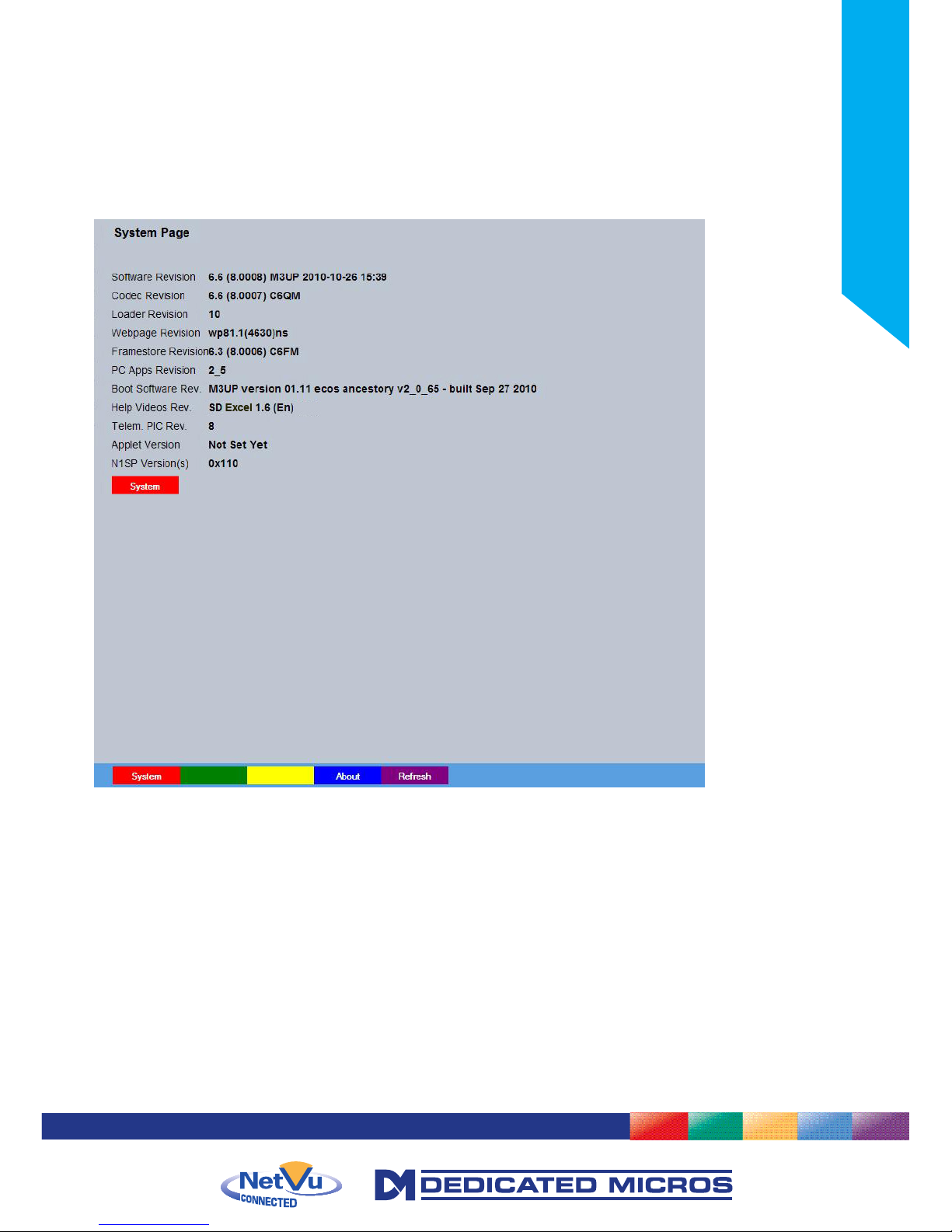
Software Menu
Software Revision This identies the version of software the unit is running.
Codec Revision This identies the codec version the unit is running.
Webpage Revision This identies the webpage version the unit is running.
Framestore Revision This identies the Framestore Revision the unit is running.
PC Apps Revision This identies the revision archive of the Viewer and associated PC
Apps software.
Boot Software Rev. Displays the infrastructure componentry software revision.
Help Videos Rev. This identies the version of Help Videos installed on the unit.
Note: Refer to ‘Go To Viewer->Help Videos’ for guidance on viewing the embedded Help Videos.
Telem PIC Rev. This identies the version of the Telemetry control device installed on
the unit.
Applet Version This identies the applet version installed on the unit
Note: Refer to ‘Display Settings->Viewer Defaults’ for guidance on using a remote applet (this can
lessen load times when accessing multiple DVRs/Servers).
Page 30

30
SD Excel
System (Red) Select this option to return to the System menu.
About (Blue) Select to open the Status->About page.
Refresh (Purple) Refreshes the information on the current page.
Page 31

31
Installation Guide
Status
This menu details information regarding the status of the unit, notably the total time the unit has been
operating and the time since its last reset. Status log information can also be exported via the ‘Export
Logs’ option to either a CD-R/DVD-R or a USB device.
Time since last reset Details the time since the unit was last reset.
Total running time Details the total time the unit has been operational.
Reset code The last reset code used is displayed.
Restart reason The reason for the last restart is displayed.
Codec Up to four codecs are installed within the unit (dependent on model).
Cameras are assigned to the codec in the following sequence: Camera
1 is assigned to Codec 1, Camera 2 to Codec 2, Camera 3 to Codec
3, Camera 4 to Codec 4, Camera 5 to Codec 1, Camera 6 to Codec 2,
etc.
Within each Codec window, each camera channel is listed, along with
connection, recording and camera status information.
Cameras Cameras assigned to each codec are displayed..
Connected Those camera channels with cameras connected will be highlighted
light green. Those not in use will appear dark green.
Recording Those camera channels that are currently recording are highlighted
light green. Those not recording will appear
dark green.
Page 32

32
SD Excel
Cam Status Those camera channels where the connection is deemed to be
functioning correctly will be highlighted light green. Those deemed
to have failed will appear red. Camera channels with no connected
camera will appear dark green.
Alarm Status (Yellow) Select to open to the Status->Alarm page.
Rem Codec (Blue) Select to open to the Remote Codec Status page
Refresh (Purple) Refreshes the information on the current page.
Page 33

33
Installation Guide
Alarm Status
This menu details information regarding the status of the unit’s alarm contacts, alarm zones and relay
outputs.
Alarm Contacts/Zones/Relay Outputs Alarm Contacts, Alarm Zones and Relay Outputs that are in an
‘active’ state are shown light green. ‘In-active’ ones appear dark
green (not illuminated).
Alarms (Blue) Select to open to the Alarm->Inputs page
Refresh (Purple) Refreshes the information on the current page.
Page 34

34
SD Excel
About
This menu allows access to numerous system information pages. Select the an icon to view the relevant
pages, refer to ‘Appendix H - Status Pages’ for a description of each page.
System Information Select to open to the System->Attributes page.
Software Revisions Select to open to the System Settings->System->Software page.
Page 35

35
Installation Guide
Logs
The log les stored in the unit can be accessed from this page. Selected logs are displayed on the page
below.
About (Blue) Select to open the System->Status->About page.
Refresh (Purple) Refreshes the information on the current page.
Page 36

36
SD Excel
Language
This menu allows the system language to be set. Changing the System Language will effect all menu
pages. If required, the language can also be changed for the current session only.
System Language Select to change the system language setting.
Reset (Red) Select to reset the unit.
Note: The unit MUST be reset to implement system language changes, refer to
System Settings->Maintain for guidance on resetting the unit.
Session Language Select to change the language settings for the current
session only.
Choose Select to immediately activate session language changes.
Reset (Red) Select to cycle the power to the unit.
Refresh (Purple) Refreshes the information on the current page.
Page 37

37
Installation Guide
Time and Date
This menu allows the time and date to be set on the unit. Required timezone information can also be
established and the unit time synchronised to that of the PC being used to view the webpages.
System Time The current system time and date is displayed.
Current Time Zone Displays the currently selected time zone settings.
Time Format As default, the time displayed is in 12 hour format. This can be changed
to 24 hour if required.
Date Format As default, the date is entered dd/mm/yy. It can also be displayed as
mm/dd/yy or yy/mm/dd.
Set Time Enter a current time for the unit.
Set Date Enter a current date for the unit.
Set Time (Green) When current time/date as been entered, select this button to
implement changes.
Time Zone Select the relevant timezone offset from the accompanying drop down
menu.
SNTP Server A Simple Network Time Protocol (SNTP) server allows external devices
to connect and set their current date and time settings to that of the
SNTP. If required, enter the SNTP server IP
address here.
Note: It is recommended that an SNTP server is congured. Suitable networked SNTP servers can be
found here: http://support.ntp.org/bin/view/Servers/NTPPoolServers
Page 38

38
SD Excel
Alternatively most DHCP and DNS servers also run SNTP services. Contact your system
administrator for further assistance.
PC Time Displays the system time of the PC currently being used to view the
webpages.
Sync Time (Blue) Use this button to synchronise the time of the unit to that of the PC
being used to view the webpages.
Note: The PC Time and Sync Time options will only be available if viewing the menu via
the webpages.
Reset (Red) Select to cycle the power to the unit.
Set Time (Green) When current time/date as been entered, select this button to
implement changes.
System (Yellow) Select to open the System->Attributes page.
Sync Time (Blue) Use this button to synchronise the time of the unit to that of the PC
being used to view the webpages.
Refresh (Purple) Refreshes the information on the current page.
Page 39

39
Installation Guide
Serial Ports
This menu allows conguration of the unit’s Serial ports, refer to ‘Installing the Unit’ for
installation information.
Serial Port These are the four serial ports available.
Port Cong The serial ports can be congured to specic uses.
Select from:
None Switches port off
Debug Sets port for serial communications
PPP Sets port for Point to Point Protocol
Telem Sets port for Telemetry purposes
Comm Sets port for Comms purposes
EPOS Sets the serial port for connection to an
EPOS (Electronic Point Of Sale) device
Note: It is recommended that Serial port 1 be set for ‘Debug’ operations.
Interface Type Choose the type of serial interface being used. Select from RS232,
RS485 or RS422.
Baud/Parity/Data/Stop/Flow Control
These options allow the Serial port communication settings to
be congured.
Note: When a telemetry protocol is selected, these settings will default to pre-determined values and
should not normally be altered.
Page 40

40
SD Excel
Protocol This is a drop down list of serial telemetry protocols supported by the
unit.
Note: Refer to ‘Appendix F’ for a full list of supported telemetry protocols.
Reset (Red) Select to cycle the power to the unit.
Maintain (Green) Select to open the System->Maintain page
Text In Img (Yellow) Select to open the Features & Text->Text->Text In Image page
Camera (Blue) Select to open the Camera Conguration page (below).
Refresh (Purple) Refreshes the information on the current page.
Camera Conguration
This page allows conguration of some features on all 32 cameras available to the unit.
Title Titles assigned to each camera are displayed.
Mode The settings will default to ‘Colour’. If Monochrome cameras are
used, select ‘Mono’. Selecting ‘Mono’ will remove colour patterning.
If a particular channel is not in use or the camera has failed, select
‘Not Connected’. ‘Remote Codec’ is used for NetVu Connected video
sources. ‘IP Camera’ is used for all NetVu Connected cameras and 3rd
party units.
Term The unit will automatically terminate the camera input with 75Ω. This
should be disabled if the video feed is looped through to another
device.
Page 41

41
Installation Guide
Fail Rep Select this option to activate a Failure report in the event of camera
connection failure (video loss).
Buzzer Select this option to activate the onboard buzzer to report in the event
of camera connection failure (video loss).
Cam Setup (Red) Select to open the Camera->Setup page
Serial (Blue) Select to open the System->Serial page
Refresh (Purple) Refreshes the information on the current page.
Page 42

42
SD Excel
Audio
The Audio menu allows settings for the bi-directional audio channels to be edited. Audio can be recorded
from camera inputs via input 2. Challenge audio i.e. originating from an Operator using NetVu ObserVer
at a Remote Video Receiving Centre (RVRC) can be recorded via input 1. This combined audio is then
available on Audio Output 1, refer to ‘Installing the SD Excel for audio hardware installation information.
Audio 1/2 Use the drop down box to assign an audio function to each input,
‘Local’ is Audio recorded from local inputs, ‘Challenge’ audio originates
from an Operator using NetVu ObserVer at a Remote Video Receiving
Centre (RVRC).
Audio Recording Select ‘Enable’ to activate Audio recording. Note that this is a global
action which when Enabled, will result in all audio received by the unit
being recorded to the HDD.
Record Audio Challenge Select this option to record an audio challenge received via an IP
connection i.e. originating from a remote client.
Record Gain This option allows the Record Gain level to be set. This is the base
setting from which the AGC (Automatic Gain Control) will operate.
Select from 1 to 15. The default and recommended setting is 15.
Playback Volume Select a volume setting between 1 to 64 for audio playback.
Record AGC Select this option to activate the AGC function. AGC helps produce a
better quality recording by removing background
noise/distortion.
Record uncompressed Select this option to record audio in an uncompressed format.
Page 43

43
Installation Guide
Note: Recording in uncompressed format will signicantly increase the disk space used.
Reset (Red) Select to cycle the power to the unit.
Refresh (Purple) Refreshes the information on the current page.
Page 44

44
SD Excel
Features
These menus enables the activation of numerous system features. Features are grouped within four submenus: System, Network, Video and Other.
System
User Logging Enable this option to activate User Logging. Refer to ‘Appendix B’ for
further information regarding the User Logging function.
Enable External Modules Select to enable any connected RS485 alarm modules.
Text in Images Select this option to activate the Text in Images function, refer to ‘Text-
Text In Image’ for more information.
Note: When de-selected here, the ‘Text in Image’ menu will no longer be displayed in
the menu tree.
Email Reporting Select this option to activate the Email Reporting function, refer to
‘Network Settings->Email’ for more information.
Note: When de-selected here, the ‘Email Reporting’ menu will no longer be displayed in
the menu tree.
Keyboard Enable (485 bus) Select this option to enable the Keyboard 485 Bus.
Remote Reporting Select this option to activate the Remote Reporting function, refer to
‘Network Settings-Remote Reporting’ for more information.
Note: When de-selected here, the ‘Remote Reporting’ menu will no longer be displayed in
the menu tree.
Page 45

45
Installation Guide
Automatic FTP Download Select this option to enable automatic FTP downloads to upgrade the
unit and/or the webpages, refer to ‘Network Settings-FTP Download’ for
more information.
Note: When de-selected here, the ‘Automatic FTP Download’ menu will no longer be displayed in
the menu tree.
SMB Server Support Select this option to activate the SMB (Server Message Block) le
sharing function. When activated, the SMB protocol allows the unit
to access PCs operating the Windows operating system (and Linux
machines running Samba). This enables sharing of les and directories
to/from the unit. The name of the SMB Workgroup on the network
must be correctly entered in the SMB Workgroup option (see below).
It is important that the Server Name assigned to the unit via ‘Network
Settings->Server Name’ is unique within the workgroup being used.
To access the unit via a PC running SMB (and has access to the
same Workgroup); open My Network Places-Entire Network- Microsoft
Windows Network. The Workgroup containing the unit and PC(s)
should then be available. Files and folders can then be copied/added
as required.
Note: Use the 10/100Mbps network option ‘Net 2’ for SMB purposes (the unique Server Name must be
assigned via ‘Network Settings-Server Name’).
Camera Masking Select this option to activate the Camera Masking function. When
activated, any attempt to cover a connected cameras lens will be noted
and an alarm event will be logged.
System (Red) Select to open the System->Features->System page
Network (Green) Select to open the System->Features->Network page
Video (Yellow) Select to open the System->Features->Video page
Other (Blue) Select to open the System->Features->Other page
Refresh (Purple) Refreshes the information on the current page.
Page 46

46
SD Excel
Network
Secondary Web Port If the default port setting for web serving has already been allocated, it
is possible to congure a second port number
i.e. the secondary web port can be set to 8000 if the default web port
(80) is blocked by the network or rewall.
Telem UDP Port Selection Select ‘Automatic’ to enable the unit to select a suitable port for
telemetry purposes.
Select ‘Default’ to use the default port settings (1025).
Select ‘User Dened’ to use settings entered in the ‘Telemetry Port’
option.
Samba Workgroup Enter the name of the Samba workgroup to enable sharing of les and
directories to/from the unit. To access the unit via a PC running SMB
(and has access to the same Workgroup); open My Network PlacesEntire Network- Microsoft Windows Network. The Workgroup containing
the unit and PC(s) should then be available. Files and folders can then
be copied/added as required.
Max Client Connections This setting limits the number of client connections to the server. The
default value is 256 but could be increased if there is heavy network
trafc.
ARP Cache Size This setting limits the number of cache entries available in the ARP
table. The default setting of 256 is adequate for most instances
TCP Reassembly Queue Limit This setting limits the maximum number of TCP segments
allowed in the reassembly queue, to protect against a common DoS
attack.
Page 47

47
Installation Guide
Remote codec lock status
Each camera can work as a remote codec for one NetVu Connected
server. This is the most efcient means of connection to a DM server as the
camera generates the viewing and recording streams directly in the format
required, so the server does not need to reprocess them. The status shows
whether or not the camera is bound to a server as a remote codec, and if
so, it identies the server it is bound to.
System (Red) Select to open the System->Features->System page
Network (Green) Select to open the System->Features->Network page
Video (Yellow) Select to open the System->Features->Video page
Other (Blue) Select to open the System->Features->Other page
Refresh (Purple) Refreshes the information on the current page.
Video
Detected Video Standard The unit automatically detects the video standard being used i.e. PAL/
NTSC.
Video Resolution (h x v) Allows selection of the resolution, options are 704 x 576, 704 x 512 and
640 x 512
Deinterlace Filter When Enabled, this option will improve the appearance of moving
objects by applying a deinterlace lter that minimises the comb effect
that can be visible when recording high motion scenes in 4CIF mode.
It is recommended that this option be enabled when recording in 4CIF
mode.
Comb Filter Enable this option to activate the Comb Filter function. Comb Filter can
help improve the ne details of a video signal image by ltering the
luminance and chrominance separation process.
Page 48

48
SD Excel
Disable Transcoding Select to disable the unit’s transcoding capabilities. In normal
circumstances this should always remain enabled, however it can be
useful to disable the feature when conducting maintenance.
Partial Full Duplex Select to enable the Partial Full Duplex option. This feature is only
relevant when viewing in mulitiscreen mode above quad. When
selected (and viewing in MPEG mode/multiscreen above quad); only
the recorded I frames are displayed and not the P
frame data.
Segment Aspect Ratio This setting control how a 4:3 image is displayed in a multi-screen or
wide screen format on the local viewer. The available display segment
changes depending on the number of multi screen images selected for
display.
Stretch forces the image to ll the available display segment. This may
result in some distortion of the display image.
Zoom Fit forces the frame to ll the available segment completely and
proportionally. Consequently some of the image at the top and bottom
of the frame may be cropped.
Frame Fit forces the frame to ll the available segment proportionally,
resulting in black bars left and right on some multi display choices.
Note: There is no cropping or distortion on the recorded image, these settings are for display only.
System (Red) Select to open the System->Features->System page
Network (Green) Select to open the System->Features->Network page
Video (Yellow) Select to open the System->Features->Video page
Other (Blue) Select to open the System->Features->Other page
Refresh (Purple) Refreshes the information on the current page
Page 49

49
Installation Guide
Other
Auto Update Web Variables Congures the unit to update all system variables required for an
automatic upgrade without requiring conrmation. Do not check this box
if you run a customised applet.
Enable event search page Select to enable the Event Search option. When enabled, the option
will appear within the Conguration Menu tree. Refer to ‘Navigating the
Conguration Menus->Event Search’ for further details.
Enable RVRC page Select this option to activate the RVRC Remote Set/Unset/Override
function, refer to ‘Record Settings-RVRC’ for
more information.
Note: When de-selected here, the ‘RVRC’ menu will no longer be displayed in the menu tree.
System (Red) Select to open the System->Features->System page
Network (Green) Select to open the System->Features->Network page
Video (Yellow) Select to open the System->Features->Video page
Other (Blue) Select to open the System->Features->Other page
Refresh (Purple) Refreshes the information on the current page.
Page 50

50
SD Excel
Maintain
This menu allows the unit to be reset and a software upgrade to be performed via an inserted CD-R/
DVD-R or a connected USB device. Current unit settings can also be saved for future use and previously
saved settings restored.
Conguration
Default (Green) Select to return the unit to its factory default settings.
Note: Selecting the Default button will cause the system to reboot.
Save (Purple) Select to save current unit settings to the selected media.
Restore (Blue) Select to restore previously saved settings from the selected media.
Note: Selecting the Restore button will cause the system to reboot.
To/From Select the relevant media device to save to or restore from i.e. USB or
CD-R/DVD-R.
Export Logs
Export Logs (Yellow) Select to export all Logged data to a connected external device.
To Select the relevant media device to save to export to.
Server
Reset (Red) Select to cycle the power to the unit.
IMPORTANT: To upgrade the unit, insert a media device containing relevant software upgrades
and select ‘Reset‘.
Page 51

51
Installation Guide
Note: For the latest software upgrades, please refer to the Dedicated Micros website:
www.dedicatedmicros.com
Note: Selecting the Default button will cause the system to reboot.
Save (Purple) Select to save current unit settings to the selected media.
Restore (Blue) Select to restore previously saved settings from the selected media.
Note: Selecting the Restore button will cause the system to reboot.
To/From Select the relevant media device to save to or restore from i.e. USB or
CD-R/DVD-R.
Export Logs
To Select the relevant media device to save to export to.
Server
Reset (Red) Select to cycle the power to the unit.
Reset (Red) Select to cycle the power to the unit.
Default (Green) Select to return the unit to its factory default settings.
Export Logs (Yellow) Select to export all Logged data to a connected external device.
Restore (Blue) Select to restore previously saved settings from the selected media.
Save (Purple) Select to save current unit settings to the selected media.
Page 52

52
SD Excel
PowerScript Mgmt
This menu enables installed PowerScripts to be activated/deactivated on start-up. Use the tickbox(es) to
select/deselect installed PowerScripts, then select Save (Green). A system reset will be required for the
changes to take affect.
Note: Changes this page will alter the ‘Default.C’ le. If you already have a custom PowerScript on your
unit which uses Default.C, please contact Dedicated Micros Technical Support for guidance Tel:
+44 (0) 845 600 9502 for further guidance.
Reset (Red) Select to cycle the power to the unit.
Save (Green) Updates the DEFAULT.C le on the NVR to enable selected scripts on
reboot.
Refresh (Purple) Refreshes the information on the current page.
Page 53

53
Installation Guide
Display Settings
The menus under the Display Settings heading allow the unit’s Viewer display settings to be altered and
User Account details to be viewed and changed.
The Remote Monitors page allows monitors not physically connected to the unit to view camera images
received by the unit.
The Viewer Defaults page allows the Viewer menu settings to be congured.
The Display page controls how the local monitors present information. They control whether text will be
displayed on the Main or Spot monitors, the colour of that text, and how long cameras being displayed in
sequence will be shown on screen.
The Maps page allows images to be imported and used as maps displayed in the Viewer menus. Hot
spots can be added to allow quick navigation to individual cameras.
The Map Data page allows Map Cong information to be saved for future use. Previously saved data can
also be uploaded.
The User Accounts page helps protect conguration procedures by limiting access to specic users via
accounts and passwords.
Page 54

54
SD Excel
Remote Monitors
This menu allows monitors not physically connected to the unit to view camera images received by the
unit. The IP address of the server connected to the monitor (or video wall) is required. Cameras can then
be selected via the remote monitor
Up to 16 remote monitors (or video walls) can be congured. Enter the IP address of the server connected
to the monitor.
Refresh (Purple) Refreshes the information on the current page.
Page 55

55
Installation Guide
Viewer Defaults
This menu allows conguration of settings for the Viewer function. Refer to ‘Operating The Viewer’ for
more information regarding this feature.
Default settings can be congured for accessing the Viewer function via a local monitor and also remotely
via a network connection. Local settings also determine the quality of video streams received from a
remote client i.e. in Remote Monitor operation. Note that this does not affect live or playback images
originating from local system cameras.
Default Image Format Images from connected cameras can be displayed in either JPEG or
MPEG format.
Default Full Req Images displayed full screen in the Viewer menus can be shown in
either High Medium or Low resolution.
Default Quad Req Images displayed in Quad format in the Viewer menus can be displayed
in either High Medium or Low resolution.
Default Multi Req Images displayed in Multi format in the Viewer menus can be displayed
in either High Medium or Low resolution.
Default Multi Display When accessing the Viewer function, select the display format which
will initially be displayed.
Startup Multi Display When accessing the Viewer function, select the display format which
will initially be displayed.
Page 56

56
SD Excel
Startup Camera When accessing the Viewer function, select the camera image which
will initially be displayed. If one of the multi display formats has been
selected via the ‘Startup Multi Display’ option, the camera channel
selected here will be displayed in rst (top left) position. Subsequent
camera channels will be displayed in sequential order.
Video Output mode Select the display output that best suits the viewing monitor. Typically
PAL Default is most suited for a CRT monitor.
Select from:
Safe Mode
PAL Default
PAL Reduced
HD Default
HD 4X3
Note: It will be necessary to reboot the unit to implement any change to the Video Output Mode. The
unit can be rebooted via the Reset (Red) option.
Note: If there is no suitable standard conguration to suit the monitor in use, refer to ‘Appendix G -
Monitor Output’ for details on enabling more options.
Applet Location The location of the unit’s Viewer menu applet is displayed. The default
location will always be the applet installed on the unit. If accessing
multiple units via a remote connection, all can be assigned the same
Viewer applet. This will lessen the load time required when accessing
different DVRs/Servers.
For example, if a local unit and a remote DVR are to be accessed, it is
possible to set the Applet location for both DVRs as the local unit.
If viewing the unit remotely, Dedicated Micros provide a remote
applet. This remote applet can be selected via the ‘Set Location’ option.
The applet is located on the website (www.dedicatedmicros.com/software_
release/index_rmware.php). Due to possible bandwith restrictions on the
network the DVR is located, using this remote applet may improve data
transfer speeds.
Set Location Select the applet location. Choose from ‘Default location’ i.e. the applet
installed on the unit; or the ‘website’ option i.e. the
remote applet.
Reset (Red) Select to reset the unit and implement any changes made to the ‘Video
Output mode’ or ‘Applet Location’ elds.
Refresh (Purple) Refreshes the information on the current page.
Page 57

57
Installation Guide
Display
This menu allows conguration of monitor settings used when viewing camera images and text data.
Main monitor text It is possible to select text to be displayed on the main monitor. The
text displayed will include; time, date, mode of operation (Set, Unset or
Override), camera number and camera title.
Background Colour A black background appears by default around the text. It is possible to
change the colour of this background. Select from the options available
in the drop down list.
Text Colour The colour of the displayed text can be changed. Select from the
options available in the drop down list.
Sequence Dwell (secs) The sequence dwell time can be set from 5 to 99 seconds. The dwell
time is the period a camera’s images are displayed before switching to
the next camera in the sequence.
Sequence main on startup Select to sequence live views from all connected cameras on the main
monitor upon system start-up.
Enable custom segment setup Select to activate the custom segment setup feature. When selected,
a user can congure a Quad or Multiscreen layout via the Viewer
menu. The congured layout can include any camera in any available
segment.
Camera selection switches
to full screen Select to auto switch to full screen mode any camera channel selected
from multi-display (selected via the Viewer feature).
Page 58

58
SD Excel
Spot monitor text It is possible to select text to be displayed on the spot monitor. The text
displayed will include; time, date, camera number and camera title.
Spot Sequence Dwell The spot sequence dwell time can be set from 1 to 99 seconds.
The dwell time is the period a camera’s images are displayed on a
connected spot monitor before switching to the next camera in the
sequence.
Spot Sequence Setup All of the unit’s camera input channels are shown. To include any of
these camera channels in the spot monitor sequence, selected the
accompanying tickbox.
Select All (Blue) Select to add all available cameras to the Spot Monitor Sequence.
Refresh (Purple) Refreshes the information on the current page.
Page 59

59
Installation Guide
Maps
This menu allows images to be imported and used as maps that can be displayed in the Viewer Menus.
The map can then have hotspots added to allow quick navigation to individual cameras.
An overview ‘System Selection Map’ can also be added to navigate between different systems.
Congure Map Leave as ‘Local System Map’. This is the map from which connected
cameras can be accessed.
Graphic Location Enter the location of the relevant map graphic, including the full
I.P address of the server holding the map. The map image will be
displayed if linking is successful. The linked map can be in gif or jpeg
format and should not exceed 500 by 350 pixels.
Map Screen Offset These coordinates represent the top left corner of the map graphic as
displayed in the Viewer menu.
Camera Select Select which camera is to be linked to the created hotspot.
Activate Hotspot Select to activate and display the camera hotspot.
Hotspot Radius Enter the radius (in pixels) of the hotspot.
Increment by If using the Decrement (Red) or Increment (Green) buttons, enter the
size (in pixels) that the hotspot will increase/decrease.
Decrement (Red) Select to reduce size of hotspot.
Increment (Green) Select to increase size of hotspot.
Page 60

60
SD Excel
Hotspot X coord Use to position the centre of the hotspot along the X axis e.g. entering
20 would place the hotspot centre 20 pixels from the left edge of the
map.
Hotspot Y coord Use to position the centre of the hotspot along the Y axis e.g. entering
20 would place the hotspot centre 20 pixels from the bottom edge of the
map.
Note: The hotspot can also be positioned by clicking directly on the map.
Hotspot Origin (deg) This option should be used when the hotspot relates to a Dedicated
Micros Oracle Dome camera. Clicking the hotspot will send the
Oracle Dome camera to a pre-determined view (absolute positioning).
However if the dead centre of the hotspot is selected, the camera will
be viewed from its current location.
The absolute positioning point will depend on the data entered here.
A setting of ‘0’ would result in the camera facing its Original (base)
position. To change the preset position, enter a number between 1 and
360. A setting of 20 would set the preset position to 20 degrees to the
right of its ‘origin’ position, 180 would send it to face in the opposite
direction (of its base position) . Refer to the ‘Viewer Menus-Program
menu‘ for information on establishing an Origin position for a PTZ
camera.
Decrement (Red) Select to reduce size of hotspot.
Increment (Green) Select to increase size of hotspot.
Map Data (Yellow) Select to open the Display->Map Data page
Refresh (Purple) Refreshes the information on the current page.
Page 61

61
Installation Guide
Map Data
The Map Data menu allows Map Cong data to be Imported/Exported. This enables map data to be
saved and stored for future use, or used between multiple units.
Note: The Map Data menu will only be available when viewing the menu pages remotely i.e. via the
webpages.
To save map data, highlight and copy all text displayed in the Map Data text window, then save this data
as a text le.
To import data, copy relevant text from an external location and paste into the Map Data text window.
When the menu is exited, this data will be used as the Map Cong settings.
Note: If importing data, remember to rst save any current map data as required.
Map Cong (Yellow) Select to open the Display->Map Cong page
Refresh (Purple) Refreshes the information on the current page.
Page 62

62
SD Excel
User Accounts
The unit can protect conguration procedures by limiting access via usernames and passwords.
Account Types The available account types for which users and passwords can be
assigned privileges are:
• Admin FTP Assigning username and password
requirements for the Admin FTP function will
limit access to the unit via an FTP connection.
• Video FTP Assigning username and password
requirements for the Video FTP function will
limit access to the Video FTP archiving feature
(used with NetVu ObserVer).
• Telnet Assigning username and password
requirements for Telnet connections will limit
Telnet access to the unit (Telnet can be used to
upgrade the unit).
• Serial Assigning username and password
requirements for Serial connections will limit
access via a Serial link.
Page 63

63
Installation Guide
• Menu Conguration Assigning Menu Conguration access privileges
will limit access to the Conguration menus
when viewed locally. When implemented, the
user will be prompted for a username and
password before access to the Conguration
menus (via the main menu) will be granted.
• Local Users Assigning Local Users access privileges will
limit access to the Viewer pages for local users.
When implemented, the local user will be
prompted for a username and password before
access to the Viewer pages (via the main
menu) will be granted.
• Remote Users Assigning Remote Users access privileges will
limit access to the Viewer pages for remote
users. When implemented, the remote user
will be prompted for a username and password
before access to the Viewer pages (via the
main menu) will be granted.
When granting access privileges to Local and Remote Users, it is possible to limit access to specic
cameras. Using the Camera Selection segment of the Add New Account menu, enter those cameras
for which access will be permitted. Select the cameras in accordance with the input channel they’re
connected to on the rear of the unit. For example, if wanting to allow access to camera 1 to 3 inclusive,
enter: 1-3. If wanting to grant access to cameras 1,3 and 6, enter 1,3,6. If no camera data is entered,
access will be allowed to all connected cameras in both live and playback modes.
Note: There are no default usernames and passwords for any of the Account Types. If none are
assigned, access will be granted to all users and no request for a username and password will be
made.
Account List When an Account Type is highlighted, details of users with access will
be displayed.
Add Highlight an administration feature i.e. Serial and select ‘Add’. Enter the
new User Name and Password. That user’s name will now be displayed
in the account list.
Modify/Delete To modify or delete a user’s settings, highlight the user in the list and
press the relevant button to Modify or Delete.
IMPORTANT: If passwords are implemented and then forgotten, it is likely the unit will need to be
returned to Dedicated Micros for unlocking.
Add (Red) Highlight an administration feature i.e. Serial and select ‘Add’. Enter the
new User Name and Password. That user’s name will now be displayed
in the account list.
Modify (Green) To modify user setting, highlight the user in the list and press to Modify.
Delete (Yellow) To delete a user, highlight the user in the list and press to Delete.
Page 64

64
SD Excel
Camera Settings
The Camera Settings menus allow conguration of cameras connected to the unit. Refer to the individual
menus for further details.
The Setup page allows the quick conguration of all connected local camera channels (with a dynamic
preview available).
The Overview menu details the general settings assigned to each of the local
camera channels.
The IP Stream Inputs menu allows the selection of High, Medium and Low resolution settings for video
sources originating from a network based source i.e. IP Server. These streams are congured on
the remote device. This feature is predominately intended for use with 3rd party IP camera streams
(connected via the 3rd party IP camera unlock feature).
The Intelligent PTZ menu details the Dedicated Micros Oracle Domes connected to the DVR.
Page 65

65
Installation Guide
Setup
This menu allows the conguration of active camera channels.
IMPORTANT: The menu options displayed will differ depending on the camera ‘Type’ and ‘IP
Mode’ selected.
Note: Ideally any setup options available locally on the camera should rst be used to best obtain a
suitable image quality.
Mono/Colour Camera
Camera Select a camera channel for review and adjustment.
Camera Nuisance Count This is a repetitive detector value. When a camera failure alarm is
received on the unit, it will store the alarm time and monitor the number
of times the same alarm is triggered within an hour period. If the
detector is triggered the number of times entered here, the unit will set
the camera to ‘No Connection’. To disable this feature, leave the setting
as ‘0’.
Title Assign a recognisable name to the camera. This will be displayed in
all references to the camera in the both the Conguration and Viewer
menus.
Type The settings will default to ‘Colour’. If Monochrome cameras are used,
select ‘Mono’. Selecting ‘Mono’ will remove colour patterning. Select’
‘IP’ for an IP Camera. If a particular channel is not in use or the camera
has failed, select ‘No Conn’.
Page 66

66
SD Excel
IMPORTANT: The menu options displayed will differ depending on the camera ‘Type’
selected here.
Fail Rep Select this option to generate a Failure report in the event of camera
connection failure.
Telemetry If a telemetry capable camera is connected, the appropriate control
protocol should be selected from the accompanying drop down list,
refer to ‘Appendix F’ for details of supported
telemetry protocols.
Default to preset If a telemetry camera has been assigned a preset position, select
the chosen preset position here. Enter the time period (in minutes) of
inactivity which will result in the camera moving to its preset position,
refer to Viewer menus->Program Page for guidance on assigning
camera presets.
after X mins Refer to ‘Default to preset’.
Note: The following settings will change depending on the type of camera connected.
If a Local Analog Camera is selected
Colour Select a colour value from -8 to +8 via the slidebar or enter a number
directly into the accompanying textbox.
Brightness Select a contrast value from -8 to +8 via the slidebar or enter a number
directly into the accompanying textbox.
Page 67

67
Installation Guide
IP Camera
If a NetVu Connected IP Source is selected
IP Type Select the type of NetVu Connected source the camera stream is
originating from. Select from:
‘NetVu Server’ - i.e. DVIP Server, DVIP RT, SD,
SD Excel, EcoSense.
‘NetVu Gen 2’ - i.e. DS2, BX2.
NetVu Camera’ - i.e. the CamVu 2000 from Dedicated Micros.
‘NetVu ANPR’ - i.e. the HyperSense ANPR camera from
Dedicated Micros.
IP Mode Select the IP mode used to receive incoming IP data. Select from:
Simple Stream - Received IP streams are non-compressed and are
viewed as congured on the originating source.
Recode Stream - When selected, the unit will recompress the
incoming IP stream to the record prole settings
established for this camera channel in the Prole
Record menu (Record Settings->Prole Record).
This feature is only accessable with 3rd party IP
camera when the 3rd party IP camera license has
been enabled.
Page 68

68
SD Excel
Remote codec When selected, the unit will utilise the codec in
the remote NetVu connected video server/camera
to allow change Multimode proles and perform
additional activities such as VMD and Activity
Detection as if the codec was an integral part of the
DVR. If ‘Remote codec’ is selected, the loading on
the unit’s internal codecs will be reduced.
IMPORTANT: The Remote codec option is only applicable for NetVu Connected cameras.
Note: Additional IP cameras ( further to existing local camera channels) are remote codec only.
Therefore any NetVu connected cameras will be applied above local camera level.
When ‘Simple Stream’ and ‘Recode Stream’ are selected via ‘IP Mode’, the following options will
be available:
IP Address Enter the URL address of the image source.
Channel If the URL is a multichannel device (e.g. DV-IP NV1), this species
which channel to use.
Both types
Live Trans (Red) Select to open the Network->Live Trans page
View Prole (Green) Select to open the Record Settings->Prole Record page
Basic (Yellow) Select to open the Serial Ports->Camera page.
Lens Setup (Blue) Select to open the Camera Lens Conguration page
Refresh (Purple) Refreshes the information on the current page.
Page 69

69
Installation Guide
Camera Lens Conguration
This page allows different lens de-warping techniques to be applied to connected cameras. The NVR can
de-warp Fish-eye and Depressive Fish-eye lenses to present a normal aspect image.
Title Shows the allocated name of the video source.
Lens Type Allows selection of sheye, depressive sheye and normal lens types.
Pitch Allows the image to be rotated counterclockwise by ninety degrees.
Ratio (H) Allows the horizontal ratio of a panamorphic lens to be set.
Ratio (V) Allows the vertical ratio of a panamorphic lens to be set.
Ratio x100 Allows the multiplier ratio of a panamorphic lens to be set.
Cam Setup (Red) Select to open the Camera -> Setup page
Cam Overview (Green) Select to open the Camera -> Overview page
Refresh (Purple) Refreshes the information on the current page.
Page 70

70
SD Excel
Overview
This menu details the general settings assigned to each of the local camera channels.
To edit the settings assigned to any of these cameras;
Click on Local Camera Setup to edit the settings held in the SD Excel;
Click on ‘Setup’ to open the Setup menu on the connected video source.
Refresh (Purple) Refreshes the information on the current page.
Page 71

71
Installation Guide
IP Stream Inputs
The IP Streams menu allows the selection of High, Medium and Low resolution settings for video sources
originating from a network based source i.e. IP Server. These streams are congured on the remote
device. This feature is predominately intended for use with 3rd party IP camera streams (connected via
the 3rd party IP camera unlock feature).
Note: The IP Stream needs to be set to Simple Streaming on Camera->Setup.
Note: There is only normal ‘non event’ recording for connected IP cameras.
Channel Select a camera channel for review and adjustment. Only those
cameras designated as ‘IP’ in the Camera Setup menu will be available
(Conguration menu:Camera Settings->Camera Setup).
Copy to all Select this option to apply current settings to all
connected cameras.
The following options can be congured for Set, Unset and Override record proles when operating
under Normal (non Event) conditions. Refer to Conguration Menu:Record Settings->Prole Record for
information regarding record modes.
Comp Select image compression format (MPEG or JPEG).
Page 72

72
SD Excel
Res For both MPEG and JPEG recording, select either High, Medium or
Low quality resolution settings.
Note: To view a local third party IP camera ‘live’, IP recording should be set to MPEG.
IP Camera (Yellow) Select to open the IP Camera Conguration menu.
Schedule (Blue) Select to open the Schedule->Setup page
Refresh (Purple) Refreshes the information on the current page.
IP Camera Conguration
Channel Select a camera channel for review and adjustment. Only those
cameras designated as ‘IP’ in the Camera Setup menu will be available,
(Camera->Setup).
Mode Select the IP mode used to receive incoming IP data.
Select from:
Simple Stream - Received IP streams are non-compressed and are
viewed as congured on the originating source.
Recode Stream - When selected, the unit will recompress the incoming
IP stream to the record prole settings established
for this camera channel in the Prole Record menu
(Record Settings->Prole Record). This eature is
only accessable with 3rd party IP camera when the
3rd party IP camera license has been enabled.
Page 73

73
Installation Guide
Remote codec When selected, the unit will utilise the codec in the
remote NetVu connected video server/camera as if
it was directly connected inside the DVR. Thus the
user can change Multimode proles and perform
additional activities such as VMD and Activity
Detection as if the codec was an integral part of the
DVR. If ‘Remote codec’ is selected, the loading on
the internal codecs within the unit will be reduced.
IMPORTANT: The Remote codec option is only applicable for NetVu Connected cameras.
Note: Additional IP cameras ( further to existing local camera channels) are remote codec only.
Therefore any NetVu connected cameras will be applied above local camera level.
When ‘Simple Stream’ and ‘Recode Stream’ are selected via ‘IP Mode’, the following options will
be available:
URL Enter the URL address of the image source.
Port If required, edit the port input data. This will default to 80 (HTTP).
Chan If required, edit the channel input data.
PPS Edit the PPS (Pictures per Second) recording settings.
Recode Select to activate the recode option.
When ‘Remote Codec’ is selected via ‘IP Mode’, the following options will be available:
IP Address Enter the URL address of the image source.
Channel If required, edit the channel input data.
IP Camera (Yellow) Select to open the Camera->IP Stream Inputs page.
Camera (Blue) Select to open the Serial->Camera page.
Refresh (Purple) Refreshes the information on the current page.
Page 74

74
SD Excel
Intelligent PTZ
Status
This page details the Dedicated Micros Oracle Domes connected to the system.
Refresh (Purple) Refreshes the information on the current page.
Page 75

75
Installation Guide
Record Settings
The Record Settings menus allow conguration of the unit’s record functions. Record settings can
be congured for normal operation, on alarm, by schedule and for set holiday and weekend periods.
Selected video data can be saved and protected. Refer to the individual menus for further details.
The Default page allows the basic Recording settings to be edited.
The Prole Record page allows the recording conguration to be based on specic priorities. The record
rate and quality can be customised to respond appropriately to the alarms and time of day.
A high degree of control and exibility is possible using these options.
The JPEG Trigger page allows
conguration of the pre trigger feature (for cameras recording JPEG mode
only). When enabled, the pre-trigger feature will buffer and store alarm recording prior to an event trigger
The Holiday and Weekend page enables Set mode to be activated for individual dates i.e. public holidays
or weekends.
The Protect Video page allows previously recorded data to be protected and retained. If needed, all
recording can be halted and saved video deleted.
The AoE Setup page allows conguration of the units ATA over Ethernet (AoE) function. AoE is a network
protocol designed for simple high-performance access of storage devices over Ethernet networks.
Importantly the external storage device must be located on the same network as the unit.
Page 76

76
SD Excel
Default
The unit has a range of pre-dened congurations available. As standard the unit can record at 6pps
MPEG4 for up to 120 days (dependent on model). Alternatively the unit can be congured for 2pps JPEG
recording on each camera or for MultiMode operation (note that this will result in the record duration
being determined by the time period the unit is in alarm).
Days Recording Displays the record duration possible using the
current conguration.
Camera Settings Choose the rate of non alarm recording to be used from the range of
preset recording proles. Select from Advanced Rate MPEG4 6pps,
Advanced Rate JPEG 3pps or MultiMode recording.
Record Duration/Enhance Quality The recording duration can be limited to a set number of days; allowing
the recording quality to be enhanced for a shorter
storage period.
Refresh (Purple) Refreshes the information on the current page.
Page 77

77
Installation Guide
Prole Record
It is possible to set the unit recording conguration based on specic priorities.
The MultiMode recording
feature offers the ability to set different recording rates, resolutions and compression formats across
unset, set and override modes for each individual camera. By varying the quality, bit rate and le
size of recorded images, the MultiMode function enables the recording capabilities of the unit to be
greatly increased. The Prole record menu can be accessed in a Simple format or in Advanced mode.
The Advanced mode offering greater opportunities to dynamically edit individual cameras recording
capabilities.
What is Turbo mode?
Turbo mode allows video images from any analogue camera or 3rd Party IP recoded camera to be
recorded and streamed at the maximum possible rate without the need to congure individual settings.
Turbo mode must be set Globally and will result in MPEG record rates of 25pps@2CIF/CIF/QCIF.
Note: When Turbo Mode is selected, there will be only ONE congurable Record Prole across ALL
cameras. The unit then matches the live transmission rate to the congured record rate. This
enables a ‘doubling’ of performance. Only the ‘Low’ and ‘Medium’ Live Transmission proles
are available for conguration (Network Settings->Live Transmissions). Low and Medium
transmission settings are congurable to allow video streaming over low bandwith IP connections
and are limited to CIF for this purpose.
Page 78

78
SD Excel
Simple Record
Menu View Switch to the Advanced Prole Record menu.
IMPORTANT: If Turbo mode is ‘Disabled’ and record settings have been congured which
will exceed the unit’s Codec performance threshold. A warning message will
be displayed informing the user that the ‘Unit needs to be in turbo mode’. If the
unit is currently in turbo mode and the currently congured record settings do
not warrant turbo mode, a message will be displayed informing the user that
‘At the current settings the unit does not need to be in turbo mode’.
The codec’s performance thresholds are detailed in the About-Codec Loading
menu (System Settings->Status->About->Codec Loading)
Days Recording Displays the record duration possible using the current conguration.
Channel Enables selection of a specic camera for editing.
Copy To End Select to copy the current prole record settings to all camera channels.
Copy To Next Select to copy the current prole record settings to the next
camera channel.
Filter by Connected cameras are available to be sorted by the resolution, select
the resolution of cameras to be displayed and congured.
Turbo Mode Select to activate the Turbo mode function (see ‘What is Turbo mode?’ for a
description of Turbo mode and
its benets).
Unset/Set/Override Normal Shows the recording prole used by the camera if no Timer Functions are
applied and the camera is operating under Normal (non Event) conditions.
Refer to the ‘Schedules’ section for further details.
Page 79

79
Installation Guide
Unset/Set/Override Event Shows the recording quality that will be used by the camera during an
Alarm or Event. Note that Set and Override schedules will be used only
when Timed Schedules are applied. Refer to the ‘Schedules’ section for
further details.
Note: When Turbo mode is selected, there will be only ONE congurable Record Prole across ALL
cameras. The unit then matches the live transmission rate to the congured record rate. This
enables a ‘doubling’ of performance. Only the ‘Low’ and ‘Medium’ Live Transmission proles
are available for conguration (Network Settings->Live Transmissions). Low and Medium
transmission settings are congurable to allow video streaming over low bandwith IP connections
and are limited to CIF for this purpose.
Note: Unset, Set and Override modes can be given more recognisable titles i.e. Day, Night, Weekend
via the Schedule menu (Record Settings->Schedule).
Comp Select image compression format (MPEG, JPEG).
PPS The accompanying dropdown list allows the number of frames captured
per second to be set.
The pictures per second (pps) option allows either 6, 5, 2, 1, 0.5, 0.25
or 0.1 pps to be recorded.
Pictures can also be recorded at ‘Real Time’ speed, ‘3/4 Real Time’ or
‘1/2 Real Time’.
To disable record, choose the ‘No Record’ option.
Select ‘User Dened’ to use settings established in the Advanced
Prole Record menu.
Quality The accompanying dropdown list allows the quality of recorded images
to be set. Select from Maximum, Very High, High, Medium, or Low.
Select User Dened to use settings established in the Advance Prole
Record menu.
Note: The higher the Quality setting, the greater the storage space used.
Codec Load (Red) Select to open the System->Status->About->Codec Loading page
Refresh (Purple) Refreshes the information on the current page.
Page 80

80
SD Excel
Advanced Record
Menu View Switch to the Simple Prole Record menu.
Note: When Advanced Record settings have been changed, it is not possible access the Simple
Record menu until the newly congured Advanced Record settings have been applied. To do this,
open the Record menu and select the ‘Save’ option. It will then be possible to return to the Prole
Record menu and access Simple Record.
IMPORTANT: If Turbo mode is ‘Disabled’ and record settings have been congured which
will exceed the unit’s Codec performance threshold. A warning message will
be displayed informing the user that the ‘Unit needs to be in turbo mode’. If the
unit is currently in turbo mode and the currently congured record settings do
not warrant turbo mode, a message will be displayed informing the user that
‘At the current settings the unit does not need to be in turbo mode’.
The codec’s performance thresholds are detailed in the About-Codec Loading
menu (System Settings->Status->About->Codec Loading)
Days Recording Displays the record duration possible using the current conguration.
Channel Enables selection of a specic camera for editing.
Copy To End Select to copy the current prole record settings to all
camera channels.
Copy To Next Select to copy the current prole record settings to the next
camera channel.
Filter by Connected cameras are available to be sorted by the resolution, select
the resolution of cameras to be displayed and congured.
Page 81

81
Installation Guide
Turbo Mode Select to activate the Turbo mode function (see ‘What is Turbo mode?’ for a
description of Turbo mode and its benets).
Unset/Set/Override Normal Shows the recording prole used by the camera if no Timed Schedules
are applied and the camera is operating under Normal (non Event)
conditions. Refer to ‘Schedule’ for further information.
Unset/Set/Override Event Shows the recording quality that will be used by the camera during
an Alarm or Event. Note that Set and Override schedules will be used
only when Timed Schedules are applied. Refer to ‘Schedule’ for further
information.
Note: When Turbo mode is selected, there will be only ONE congurable Record Prole across ALL
cameras. The unit then matches the live transmission rate to the congured record rate. This
enables a ‘doubling’ of performance. Only the ‘Low’ and ‘Medium’ Live Transmission proles
are available for conguration (Network Settings->Live Transmissions). Low and Medium
transmission settings are congurable to allow video streaming over low bandwith IP connections
and are limited to CIF for this purpose.
Note: Unset, Set and Override modes can be given more recognisable titles i.e. Day, Night, Weekend via the
Schedule menu (Record Settings->Schedule).
Comp Select image compression format (MPEG, JPEG).
Res Select image resolution format (QCIF, CIF, 2CIF or 4CIF).
Rate_kbps If MPEG4 is selected, the gure entered here will be the bit rate
allocated. A higher bit rate will provide better quality. MPEG bit rates
can be entered within the range of 45-2500K bits/second.
IMPORTANT: The bit rate allocation will be limited to the maximum rate of 2048 per camera.
Size If JPEG is selected, the gure entered here will be the size of the JPEG
transmitted (in Kbytes). JPEG le sizes can be congured within the
range of 5-45Kbytes.
PPS Select the number of pictures recorded per second.
GOP If using MPEG4 recording, select the number of images recorded within a
GOP (Group of Pictures). A GOP consists of an I-Frame (keyframe) and
following P frames.
Note: The GOP is also the rewind interval and stop interval for MPEG recording playback.
Note: An MPEG I-frame is considerably larger than a P-frame. Therefore the lower the GOP ratio, the higher
the disk space required to store recorded images.
Codec Load (Red) Select to open the System->Status->About->Codec Loading page
Refresh (Purple) Refreshes the information on the current page.
Page 82

82
SD Excel
JPEG Pre Trigger
This menu enables conguration of the pre trigger feature (for cameras recording JPEG mode only).
When enabled, the pre-trigger feature will buffer and store alarm recording prior to an event trigger.
Channel Only those camera channels set to record in JPEG mode will be
available for conguration.
Pre-Trigger (JPEG) Enabling the Pre-Trigger feature will buffer and store alarm recording
prior to an event trigger (in JPEG format). It will use the maximum
available memory dependent on other cameras requirements of the
buffer space. Select ‘Enable’ to activate.
Note: It is recommended that the Pre-Alarm option in the ‘Alarm Settings-Zone Input’ menu be set
to the same value as the Pre-Trigger setting. This will ensure successful playback of high
quality Pre-Trigger images. High quality pre-trigger images will only playback properly if review
(playback) starts prior to the pre-trigger initiation.
Pre-Trigger Duration (secs) The Pre-Trigger Duration is the maximum possible time that data will be
stored prior to an event trigger.
Refresh (Purple) Refreshes the information on the current page
Page 83

83
Installation Guide
Protect Video
This menu allows the unit to automatically protect and retain recorded data in the camera. Previously
saved data can also be unprotected. Enter a start and end time and select ‘Reload List’ . All saved video
les from the chosen time period will be shown in the upper textbox. These recorded ‘PAR’ les can then
be selected and protected via their accompanying checkboxes and the Protect option. Selected video les
can also be unprotected via the Unprotect option.
The lower textbox provides a status report detailing which video les have been protected/unprotected.
Start Date Enter a start date to protect video.
Start Time Enter a start time to protect video.
End Date Enter an end date to protect video.
End Time Enter an end time to protect video.
Protect Length (days) Enter the number of days that selected les will be protected for.
Protect Select this option to protect recorded video for the selected
time period(s).
Unprotect Select this option to unprotect recorded video selected from
the list.
Reload List This will refresh the video list according to the selections made in the
Start Time/Date and End Time/Date dialog boxes.
Select None This de-selects all the available video les.
Select All This selects all the available video les.
Page 84

84
SD Excel
List From Date/Time This dialog box allows a search to be made within the protected video
list starting from a specic Time and Date.
List To Date/Time This dialog box allows a search within the protected video list to
conclude at a specic Time and Date.
Unprot all (Red) Select to unprotect all recorded video from the list
Protect (Green) Select to protect recorded video for the chosen time period
Unprotect (Yellow) Select to unprotect recorded video for the chosen time period
Refresh (Purple) Refreshes the information on the current page
Page 85

85
Installation Guide
AoE
This menu allows conguration of the units ATA over Ethernet (AoE) function. AoE is a network protocol
designed for simple high-performance access of storage devices over Ethernet networks. Importantly the
external storage device must be located on the same network as the unit. AoE does not rely on network
layers such as IP and TCP, making it non routable i.e. routers cannot be used to forward a packet across
disparate networks. AoE packets can only travel within a single local Ethernet storage area network
(adds a physical layer of security to the information). The stored video can only be accessed by plugging
directly into an ethernet socket in the same LAN as the host. This means AoE cannot be accessed over
the Internet or other IP networks, but makes AoE more lightweight (with less load on the host), easier to
implement, provides a layer of inherent security, and offers higher performance.
Logical Devices Connected AOE Devices - Any devices in this panel are being used
by the unit to store data. They can be freed by clicking on the Release
button.
Physical Devices Available AOE Devices - Any devices in this panel are available on
the network. They can be added to the storage capability of this unit by
‘claiming’ the storage. Unavailable storage is listed as Owned. Claimed
storage capacity can be ‘released’ in the top panel.
Refresh (Purple) Refreshes the current page.
Page 86

86
SD Excel
Schedule
This menu allows the Timer Function names to be congured. The Timer Function enables the unit
to automatically be put into set/unset mode at specic times on specic days. This can help reduce
unnecessary alarm triggers. The mode will be set by the DVR that the camera is connected to.
When the unit is in Set or Unset mode, combine with different recording qualities and rates under normal
and alarm conditions for a high degree of control in a range of situations.
The Setup page allows conguration of the schedule including naming the modes of operation and
controlling when the unit changes between modes.
The Holiday & Weekend menu allows the unit to be automatically switched to Override mode for individual
days i.e. public holidays or during a weekend (or any dened period).
Page 87

87
Installation Guide
Setup
This menu allows the Timer Function names to be congured. The Timer Function enables the unit
to automatically be put into set/unset mode at specic times on specic days. This can help reduce
unnecessary alarm triggers. The mode will be set by the DVR that the camera is connected to.
When the unit is in Set or Unset mode, combine with different recording qualities and rates under normal
and alarm conditions for a high degree of control in a range of situations.
The Setup page allows conguration of the schedule including naming the modes of operation and
controlling when the unit changes between modes.
Mode/Title Enables a name to be entered for Unset, Set and Override mode.
Current Mode Shows the current timer mode according to the names entered in the
Mode/Title text boxes.
Day Time Enter the time (using the 24hr clock) when Unset mode will begin.
Night Time Enter the time (using the 24hr clock) when Set mode will begin
Refresh (Purple) Refreshes the current page
Page 88

88
SD Excel
Holiday & Weekend
This menu allows the unit to be automatically switched to Override mode for individual days i.e. public
holidays or during a weekend (or any dened period).
IMPORTANT: Holiday and Weekend settings cannot be entered when a Keyswitch has been
enabled in the Record Settings->Schedule menu.
Holidays Enter a date and press the Add button. The date will be added to the
Holiday list. To delete, highlight and select Delete.
Note: Unset, Set and Override modes may be renamed via Record Settings->Schedule.
Override Select ‘Enable’ to activate the Override (weekend) function. Set mode
will now be active for the dates outlined below.
Start Select a Start day and time for Override (weekend) mode.
End Select an End day and time for Override (weekend) mode.
Note: Override mode will remain activate each week until deselected.
Refresh (Purple) Refreshes the current page
Page 89

89
Installation Guide
Alarm Settings
The Alarm Settings menus allow conguration of the unit’s alarm functionality. Individual alarm inputs and
alarm zones can be congured. Global relays can be activated and the Activity grid set up. Refer to the
individual menus for further details.
The Inputs page allows conguration of alarm channels. Up to 19 alarm channels are available.
The Zone Inputs page enables the conguration of alarm zones. Up to 32 separate alarm zones can be
created.
The Zone Actions page enables actions such as Go to Preset to be allocated to alarm zones. Zones can
also be associated with a specic camera. On receipt of an alarm, images from the associated (primary)
camera will automatically be displayed in the Viewer menu.
The Masked Camera Det(ection) page allows cameras to be enabled for ‘masked’ detection based on a
threshold contact value and dwell time.
The VMD/Act(ivity) Response page enables conguration of responses following an VMD/Activity
Detection trigger.
The Activity page allowed activation and conguration of the Activity feature on all video inputs. The
Activity feature enables cameras to automatically detect any movement/changes within the video scene.
This can trigger a number of operations such as FTP alarm notication or an increase in the recording
rate.
The VMD page enables the unit’s VMD (Video Motion Detection) to be set-up. VMD allows a camera to
automatically detect if there is any movement/changes within specic areas of the video scene.
T
he Global Actions page allows the two onboard relay connections and global relay settings to be congured.
Page 90

90
SD Excel
Inputs
This menu allows conguration of the alarm settings, refer to ‘Installing the Unit’ for hardware installation
guidance.
Number This identies which input is being congured. The unit supports 19 on-
board alarms.
Enabled Each input must be enabled to function. If the input is not enabled and
an alarm is received, the unit will not acknowledge the alarm.
Module The alarm contacts are connected via modules. Select the module that
the contact to be congured is in.
Contact Select the Contact within the module to congure.
N_O (Normally Open Contact) N_O indicates the non-alarm state of the input. Tick the N_O checkbox
to set the corresponding input to Normally Open. The alarm will then
trigger when the input is closed (shorted). If left as Normally Closed (the
default setting), the alarm will trigger when the input is opened.
Note: If EOL alarms are to be used, this option should not be selected i.e. leave set as
Normally Closed.
EOL The End Of Line (EOL) option enables the inputs to detect any changes
in the electronic input resistance. A change outside the expected
values will result in a Tamper Alarm (short circuit or open circuit) being
detected and the system switching to alarm mode.
Page 91

91
Installation Guide
Pulse Ext (s) A pulse extension is used to prevent double triggers on a single alarm.
The pulse extension time starts on an alarm trigger. If that contact is
triggered again after the rst alarm has nished but within the pulse
extension, the second trigger will not restart the alarm, but will extend
the current alarm duration. Enter the time in seconds for this
extension.
Nuisance This is a repetitive detector value. When an alarm is received on the
unit, it will store the alarm time and monitor the number of times the
same detector is triggered within an hour period. If the detector is
triggered the number of times entered here, the unit will de-activate this
detector from triggering an alarm for an hour. The unit will continue to
monitor the detector and check how many times it is triggered during
this period. If it is again triggered more than the amount set in the
nuisance counter, it will remain de-activated for another hour. This will
continue until the trigger value falls below the nuisance count setting.
To disable this feature, leave the setting as ‘0’.
Stuck Time (min) If any of the alarms/detectors are active for a period longer than
specied here, they will automatically be omitted. This time period is set
in minutes.
Note: The arrow button displayed next to each textbox allows settings to be replicated for those
cameras listed below. This will only affect the adjacent option i.e. Enabled arrow will replicate the
Enabled setting to cameras below the clicked arrow.
Reset (Red) Select to reset the unit
Relays (Green) Select to open the Alarm->Global Actions menu
Status (Yellow) Select to open the System->Status->Alarm menu
Zone in (Blue) Select to open the Alarm->Zone Input menu
Refresh (Purple) Refreshes the information on the current page
Page 92

92
SD Excel
Zone Inputs
This menu allows the conguration of established alarm zones. A single or multiple trigger can be used
to generate an alarm. It is possible to allocate up to 32 alarm zones to carry out a combination of actions.
Use these options in conjunction with the Zone Actions menu.
Entry timer This is the number of seconds allowed for the user to enter the zone
and disable the alarms. If the alarm is not disabled within this period the
alarm will be triggered.
Exit timer This is the number of seconds from the alarm being set within which the
user must exit the set zone. If the user is still within the zone after this
time period the alarm will be triggered.
Zone An alarm zone can be established to logically groups alarms and initiate
actions when an alarm is activated, there are 32 congurable zones.
Title This information is stored along with the relevant images in the
database, ensure this has relevance to the alarm zone.
Pre-Alarm sec This is the time period prior to the start of the alarm included with the
alarm recording for archive. These images will also be protected from
being overwritten.
Note: It is recommended that the Pre-Alarm option be set to the same value as the Pre-Trigger setting
in the “Prole Record“ menu. This will ensure successful playback of high quality Pre-Trigger
images. High quality pre-trigger images will only playback properly if review (playback) starts
prior to the pre-trigger initiation.
Page 93

93
Installation Guide
Alarm Duration sec This is the minimum time period in seconds (from the start of the alarm)
that is protected from being overwritten. This time will include the alarm
trigger, the pulse extension and any post alarm recording. It will not
include pre-alarm images.
Zone Input Rule This determines which input(s) will trigger the zone alarm:
Input This sets an input or system function as the primary alarm trigger.
Select from Alarms 1-32,
Video Alarm
1-16, Preset 1-16, Disk Low, Disk
Full, Panic, Archiving Slow, Archiving Fault, Virtual 1-16, and Keyword
Channel 1-32 (which will trigger the Alarm if any or the 32 programmed
keywords are detected on the selected channel).
Zone OR Input
The Zone OR Input identies an alternative input that can also be used to
trigger the zone alarm. This means an alarm trigger can be received on
the Zone Alarm Input or the Zone OR Input for the zone to be activated.
Zone AND Input
The Zone AND Input identies that an alarm trigger needs to be
received on both the Zone Alarm Input and the Zone AND Input for
the zone to be activated and the alarm action to the
automatically initiated.
Zone NOT Input
The unit will only issue the alarm actions if the trigger is received on the
zone alarm input and NOT on the Zone input.
Alarm 24Hr This option can be enabled for alarms that do not require change at
a
ny time and are to remain as programmed i.e. Panic Alarm. When this is
selected, the Set, Unset and Override options are disabled
.
Entry Route Zone This creates deferred alarms along a specied route while the
entry time is active. This is in compliance with BS8418 (the British
Standard for remote video reporting centres). Diverting from the entry
route during the countdown will result in the alarm being triggered
immediately. This allows staff entry without triggering an alarm prior to
switching the system to Set mode.
Exit route Zone This creates deferred alarms along a specied route while the exit time
is active. This is in compliance with BS8418 (the British Stan
dard for
remote video reporting centres). Diverting from the exit route during the
countdown will result in the alarm being triggered immediately. This allows
staff to exit without triggering an alarm
.
Exit Terminator This will trigger the exit timer if the system is set. A countdown timer will
automatically start when the alarm is activated and ensure the alarm
system is not activated by other specied alarm triggers for the Set time
i.e. allowing a Guard to exit a building.
Entry Initiator This will trigger the entry timer if the system is set. A countdown timer
will automatically start when the ‘primary’ alarm trigger i.e. front door,
is actioned. This ensures the alarm system is not activated by other
specied alarm triggers for the set time
Enable in Unset Each alarm can be congured to be active when the unit is in a specic
operation mode. Enable this for the zone alarm to be active in Unset
operation mode.
Enable in Set Each alarm can be congured to be active when the unit is in a specic
operation mode. Enable this for the zone alarm to be active in Set
operation mode.
Enable in Override Each alarm can be congured to be active when the unit is in a specic
operation mode. Enable this for the zone alarm to be active in Override
operation mode.
Activity (Green) Select to open the Alarm->Activity menu
Zone Act (Yellow) Select to open the Alarm->Zone Actions menu
Alarm in (Blue) Select to open the Alarm->Inputs menu
Refresh (Purple) Refreshes the information on the current page
Page 94

94
SD Excel
Zone Actions
This menu allows actions to be allocated to individual alarm zones; Primary and Secondary cameras
can be allocated to the zone and actions undertaken following alarm activation. This page should be
congured in conjunction with the Zone Inputs menu.
Zone Select a zone (alarm) to congure.
Alarm Colour This displays the local alarm text in the selected colour and can be
useful in prioritising alarms. Options available are Red, Green, Blue,
Yellow, Cyan and Magenta.
Primary Camera This allows a camera to be assigned as the primary camera associated
with the Alarm Zone. The primary camera will be displayed when an
alarm in this zone is triggered.
Create Database Entry An alarm activation will be added to the database. The zone title will be
used as part of the entry information.
Alarm Relay Select to trigger an alarm relay following zone activation. Select the
specic relay via the ‘Relay’ option.
Prole Change Select to enable the unit to switch from Normal to Event recording
following alarm zone activation.
Play Audio It is possible to play associated audio upon zone alarm activation.
Alarm Reporting This must be enabled to allow the unit to send an alarm notication to
an external destination i.e. an RVRC reporting via NetVu ObserVer.
Archive Select to ensure the unit automatically downloads alarm images via an
FTP connection to an FTP server.
Page 95

95
Installation Guide
Add Still Image This will record a still image of the trigger along with the standard
recording. This can then be sent on to an external destination.
Email Image If this option is selected, a JPEG will be added to the reporting email (if
Email Reporting is selected).
Protect alarm Images
Alarm images can automatically be protected from being overwritten
.
Switch Spot Monitor
Select to display the alarm zone Primary camera on the Spot Monitor.
Goto Preset It is possible to action a camera to automatically be sent to a preset
position when an alarm is triggered.
Email Reporting The unit can send an email when an alarm is detected. Refer to
‘Network->Email’ for further information.
VMD/Activity Inhibit Select to inhibit (ignore) the VMD/Activity detection feature. Refer to
‘Alarm Settings->Activity Setup’ for further information.
Enable Buzzer Select to activate the unit’s internal buzzer upon alarm receipt.
Relay Select an onboard or external relay to automatically close on receipt of
an alarm.
Relay Duration Enter (in seconds) how long the relay is to remain closed.
Alarm Image Snapshot Delay This gure allows a delay to be introduced before an alarm snapshot is
taken. This is used when the alarm relates to a PTZ camera which has
to travel to a preset position.
Play Audio Message Following a Zone alarm trigger, a specic audio message
can be played.
IMPORTANT: Audio messages must be uploaded to the unit in mono 8k wav format only.
The following naming convention must be used: messageXX.wav
i.e. message00.wav, message01.wav etc.
An FTP client should be used to place the wav les in the following folder:
\mdd0\messages folder .
Switch Main Monitor Select to display the alarm zone Primary camera on the
Main Monitor.
Preset Camera Activate a telemetry camera to move to a preset position on receipt of
the alarm.
Preset Select the preset the activated telemetry camera (above) will move to.
Cam Options (Yellow) Select to open the Zone Action Camera Conguration menu.
Rem Report (Red) Select to open the Network->Remote Reporting menu
Email (Green) Select to open the Network->Email menu
Cam Options (Yellow) Select to open the Alarm->Zone Actions->Zone Action Conguration
menu
Relays (Blue) Select to open the Alarm->Global Actions menu
Refresh (Purple) Refreshes the information on the current page
Page 96

96
SD Excel
Zone Actions Camera
Zone Select a zone (alarm) to congure.
Secondary Cameras This setting gives the facility to assign additional cameras to the zone.
These cameras will become part of the alarm sequence shown in the
Viewer menus when the alarm zone is triggered.
Zone Act (Yellow) Select to open the Alarm->Zone Actions menu
Relays (Blue) Select to open the Alarm->Global Actions menu
Refresh (Purple) Refreshes the information on the current page
Page 97

97
Installation Guide
Masked Cam Det
The unit has the capability to identify if a video input has been covered (by hand, spray paint, etc.) to
prevent video images being viewed and recorded. The Camera Masking option identies normal levels of
contrast and uses them as a base line. It then compares these against a user dened minimum contrast
level. If the video input goes below this user dened level an event is generated on the unit.
Simple Activation
Simple Activation Select Zone Activation
Camera Displays the camera number and camera title as congured on the
Camera Setup page.
On Enables or disables the feature on the camera.
Dwell This is the delay the unit will wait before declaring the camera
is masked.
Threshold Denes the threshold the system uses to dene that a camera is
masked. It will be necessary to adjust this gure to avoid
false alarms.
Note: In low light conditions, enter a gure below the contrast threshold (see below). Experiment with
camera masking alarm activation until a gure is selected were false alarms are avoided
Page 98

98
SD Excel
Contrast D
enes the contrast threshold the system uses to dene that a camera is
masked. Different cameras have different characteristi
cs.
On Mask/Clear Select the Zone alarm that will be activated on camera masking or
camera clear detection (if ‘Zone Activation’ is selected at the top of the
page).
Refresh (Purple) Refreshes the information on the current page
Page 99

99
Installation Guide
Zone Activation
On Mask Denes the Zone trigger that will be activated when the view
is masked.
On Clear Denes the Zone trigger that will be activated when the view
is unmasked.
Refresh (Purple) Refreshes the information on the current page
Page 100

100
SD Excel
VMD/Activity Response Setup
This menu enables response conguration following activity trigger on a selected camera channel.
VMD Pulse Ext The pulse extension extends the trigger period to avoid double triggers
of VMD occurring, i.e. If a second incident of VMD is received, after the
rst alarm is nished but within this period, the unit will not create a new
event.
Channel Select the camera input for conguration from the drop down list.
Copy To All Select to copy the current Activity Response settings to all
camera channels.
Detection Type
Each camera input can be congured for either ‘VMD’ or ‘Activity’ detection. To
assign no detection settings to the camera, select ‘None’
Note: Whichever Detection option is selected here, will result in the camera channel being only
available for editing in the relevant conguration menu i.e. if Activity is selected for Channel
1;
this channel can only be edited for Detection in the Activity Setup menu and not the VMD
Conguration menu.
Activity To Trigger Following Activity activation, select ‘Simple Response’ to trigger specic
chosen responses from the options detailed below. Select ‘Zone’ to
apply the Zone Input rules as congured in the Zone Input menu. Refer
to ‘Zone Input’ for more information.
Note: When Activity to Trigger is set to ‘Zone’; the options detailed below are unavailable.
Create Database Entry When selected, an alarm entry will be added to the
Event database.
 Loading...